
1304
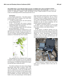
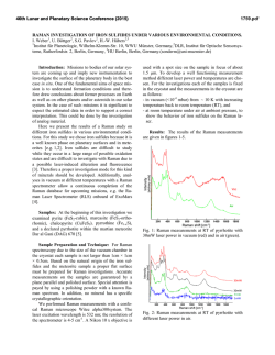
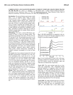
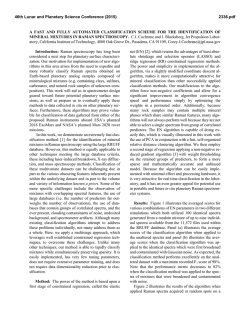
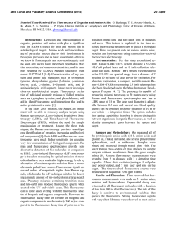
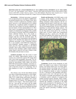
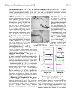
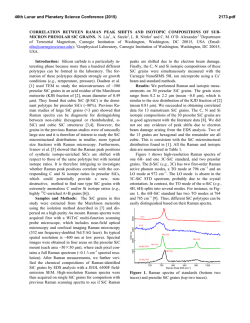
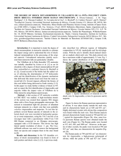
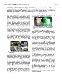
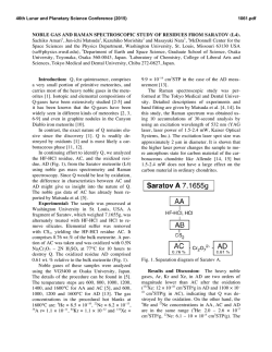
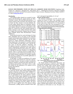
46th Lunar and Planetary Science Conference (2015)
1304.pdf
ADVANCES IN TIME-RESOLVED RAMAN SPECTROSCOPY FOR IN SITU CHARACTERIZATION OF
1
1
1
1
2 1
MINERALS AND ORGANICS. J. Blacksberg , E. Alerstam , Y. Maruyama , C. Cochrane , G.R.Rossman , Jet Pro-
pulsion Laboratory, California Institute of Technology, 4800 Oak Grove Dr., Pasadena, CA 91109, [email protected], 2California Institute of Technology, Division of Geological and Planetary Sciences,
Pasadena, California 91125, [email protected].
analyses within a microtextural context, essential for
Introduction: We present recent developments in
understanding surface evolutionary pathways. The
instrumentation for in situ planetary time-resolved
addition of time resolution to Raman spectroscopy
Raman spectroscopy, leading to improved performance
adds the unique ability to identify and place within
and identification of both minerals and organics. The
context both minerals and organics regardless of backTime-Resolved Raman Instrument shown in Figure 1
ground interferences, showing great promise for planebuilds on the widely used 532 nm (green) laser Raman
tary surface exploration to multiple target bodies identechnique, but uses time resolution to detect Raman
tified in the Planetary Science Decadal Survey [6].
spectral signatures while eliminating pervasive backThe technique takes advantage of the fact that fluoresground interference caused by fluorescence from mincence
can be distinguished from Raman in the time
erals and organics. The same technique enables operadomain.
Raman scattering is instantaneous while fluotion in daylight conditions without the need for light
rescence processes are associated with decay times
shielding.
which vary from ps to ms. In natural mixed-phase
samples, there can be several fluorescent phases, leading to both long lifetime (mineral) and short lifetime
(organic) fluorescence. An illustration of fluorescence
rejection using time resolution is shown in Figure 2.
Figure 1. High-level schematic of the Time-Resolved
Raman Spectrometer, as illustrated for potential mounting
on a Rover arm.
By combining capabilities for the identification of
minerals present in geological materials, with capabilities to detect organic matter, laser Raman spectroscopy
provides a robust in situ method for potential future
exploration of planetary surfaces [1-5]. Raman is a
non-destructive surface technique that requires no
sample preparation. Because each band in a Raman
spectrum represents interaction of the incident light
with a vibrational mode in the crystal, it is highly material specific and can be used for identification and
structural characterization of unknown samples. In
combination with micro-scale imaging and point mapping, Raman can be used to directly interrogate rocks
and regolith materials, while placing compositional
Figure 2. Illustration of fluorescence rejection with timeresolved Raman spectroscopy, where only the signal that
falls within the chosen time gate is collected. Mineral
fluorescence is typically long-lifetime and is easily rejected using a 1 ns gate. Organics present a greater challenge
as they often exhibit faster fluorescence lifetimes (ps to
ns) as illustrated in the orange and red curves.
Instrument Overview: In order to effectively separate
Raman from fluorescence background, sub-ns time
gating is required. This is accomplished with the use of
two essential components: a fast time-resolved detector
and a short-pulse laser. Our detector is a custom developed 1024x8 array of Single Photon Avalanche Diodes
(SPADs) fabricated using standard silicon CMOS processing, capable of sub-ns time-gating, and operating
over a large temperature range without the need for
cooling, using very little power [7]. SPADs represent
the enabling technology for time-resolved Raman
spectroscopy in a miniaturized format [8,9].
46th Lunar and Planetary Science Conference (2015)
Figure 3. Raman spectra showing the benefit of timeresolved Raman for smectite clay, an important class of
alteration minerals especially relevant to Mars. The measurement performed on the JPL time-resolved Raman instrument prototype is shown in green and the standard laboratory Raman spectrum measured on a Renishaw spectrometer is
shown in red.
SPADs operate in single photon counting mode, with
entirely digital output. In the time-resolved Raman
spectrometer, the SPAD detector synchronizes with the
pulsed laser to collect photons only when the laser
pulse is active, thereby rejecting fluorescence and ambient light which can be intense in between laser pulses. In addition to the detector, the need for a short time
gate places constraints on the pulsed laser, which must
provide a short pulse width as well as a high average
power, while keeping the peak power below the sample damage threshold. Our current prototype instrument uses a commercially available 532 nm passively
Q-switched microchip laser, operating at 40 kHz repetition rate with ~ 600 ps, 1.5 µJ pulses. Figure 3 shows
the performance capabilities of this instrument, where
high background fluorescence is not an impediment to
attaining high quality Raman spectra on Mars-analog
minerals such as smectite clays.
Advances in Instrumentation: Finally, we discuss
our most recent advancements for further improving
the signal-to-noise performance of the time-resolved
Raman instrument. The improved performance is especially notable for dark samples and those containing
organics. For example, kerogen and other fossilized
biosignatures present a challenge in that they often
exhibit short lifetime fluorescence, and they can be
dark and thus susceptible to laser damage. The key
advancement that promises great improvement in our
ability to identify these challenging samples makes use
of a new laser technology – high speed microchip
(HMC) lasers [10-12]. These are higher repetition rate
lasers (MHz) with lower energy per pulse that are currently under development. Raman spectra with our first
HMC laser setup show the potential for greatly improved performance as seen in Figure 4.
1304.pdf
Figure 4. Raman spectra of silicon, a typical dark sample,
showing the benefits of HMC lasers over conventional microchip lasers. The black curve shows that using our 40 kHz
commercial microchip laser, the silicon sample is damaged
and the associated broadband plasma emission is visible at
1.65 mW averge power (~41 nJ pulse energy). The red curve
show a broadband-free silicon spectrum acquired at almost
the same average power, 1.5 mW, with an un-optimized
prototype HMC laser setup (~650 kHz rep. rate, ~180 ps
pulse duration). The lower pulse energy, ~2.3 nJ, is below
the damage threshold resulting in a clear Raman spectrum.
This strategy of moving towards lower pulse energies at
higher repetition rates effectively eliminates the sample
damage related to the pulsed laser operation, enabling measurements at higher average powers, and ultimately leading
to a stronger detected Raman signal.
Acknowledgements: The research described here was
carried out at the Jet Propulsion Laboratory, California
Institute of Technology, under a contract with the National Aeronautics and Space Administration (NASA).
Continuous-wave Raman measurements were performed at the Mineral Spectroscopy Laboratory at the
California Institute of Technology. SPAD development
was performed at Delft University of Technology by
the group of Professor Edoardo Charbon.
References: [1] D.D. Wynn-Williams et al., Icarus,
144, 486-503 (2000), [2] A. Wang, et al. J. Geophys.
Res., 108 (E1), 5005 (2003), [3] S.K. Sharma et al.
Spectrochim. Acta Part A, 68, 1036-1045 (2007), [4]
L. Beegle et al., Proceedings of the 11th International
GeoRaman Conference 2014 (LPI) #5101, (2014)., [5]
S.M. Clegg et al., Applied Spectroscopy, 68 (9), p.
925-936 (2014), [6] National Academy of Sciences/National Research Council (NRC) Decadal Survey
of Planetary Sciences, 2011 [7] Y. Maruyama et al.,
IEEE JSSC, 49 (1) (2014) [8] Blacksberg, U.S. Patent
No. 13/925,883, 2013, [9] J. Blacksberg et al. Optics
Letters, 36 (18), 3672-3674 (2011), [10] A. Steinmetz
et al., Appl Phys B, 97: 317–320, 2009, [11] E.
Mehner et al., Appl. Phys. B, 2013, [12] B. Bernard et
al., Proc. SPIE 8960, Laser Resonators, Microresonators, and Beam Control XVI, 89601D, 2014
© Copyright 2026