
A NEW TOOL FOR CONTROLLING STEREO PAIRS TO LASER
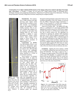
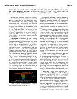
46th Lunar and Planetary Science Conference (2015)
2373.pdf
AUTOTRIANGULATION: A NEW TOOL FOR CONTROLLING STEREO PAIRS TO LASER ALTIMETRY Aaron Kilgallon1 , Jon Stephens1 , Sarah Sutton1 and Joel Mueting1 . 1 Lunar and Planetary Laboratory,
University of Arizona, Tucson, Arizona 85721 USA; [email protected]
Introduction: Currently operating orbital cameras, such as the High Resolution Imaging Science
Experiment (HiRISE) [1] and Context Camera (CTX)
[2] on the Mars Reconnaissance Orbiter (MRO), and
the Lunar Reconnaissance Orbiter Camera - Narrow
Angle Camera (LROC NAC) [3], are returning stereo
images that are being used to make Digital Terrain
Models (DTMs). The process used by many groups
(e.g. [4, 5, 6]) incorporates a combination of the
Integrated Software for Imagers and Spectrometers
(ISIS, http://isis.astrogeology.usgs.gov) and SOCET
SET ( c BAE Systems, Inc.) software, after the method
described in [7]. The images are pre-processed in
ISIS, and then controlled in SOCET SET’s interactive
interface, Multi-Sensor Triangulation (MST). This
process involves matching the image data to a set of
laser altimetry data from either the Mars Orbiter Laser
Altimeter (MOLA) [8], for HiRISE or CTX, or Lunar
Orbiter Laser Altimeter (LOLA) [9] for LROC. To do
this manually requires a skilled operator, time, and a
certain degree of subjectivity.
To reduce the ambiguity of the process, and to quickly
quantify errors, we developed autoTriangulation, a
standalone program that takes the DTM and the laser
altimetry and finds a best fit between the two. The
output of autoTriangulation includes updated ground
point coordinates which can then be used to adjust the
solution within SOCET SET. autoTriangulation speeds
up DTM production, provides consistent solutions, and
reduces the extensive training time required for producers. We will make autoTriangulation freely available to
the community as a tool in DTM production.
Inputs and Parameters: autoTriangulation runs on
the Windows command line interface. In its primary
mode, the program expects three input arguments, in
any order: a geotiff (exported DTM from SOCET SET),
the laser track file (in .csv, .tab, or .dbf format), and the
MST report file (.rep) from SOCET SET. Further parameters may be specified after these files. Entering
no arguments will display the program help documentation. There are a number of parameters that can be
adjusted such as: the number of iterations, whether the
project is a HiRISE or LROC project (error mapping
and the solution parameters are handled slightly differently), whether orbits are to be excluded from the laser
data, selection of a linear or a quadratic fit with respect
to the laser data, as well as several statistical filtering
and convergence parameters. Command line options
are detailed in Table 1. The current version of autoTriangulation works only with projects in equirectangular
coordinate systems. Future updates will handle polar
projects.
Algorithm: autoTriangulation applies iterative,
least-squares minimization to deriving the final solution
for the DTM. Error is calculated using the difference
in elevation between the laser shot and corresponding
coordinate in the geotiff. The program has several
internal functions that are implemented within each
stage: translational motion of the DTM, rotation of
the DTM, and finally a linear or quadratic surface fit
to the error between each data set. This procedure is
then repeated with a more constrained set of parameters
for each stage. This method does not guarantee global
convergence of the fit, but the default parameters have
been selected empirically to yield the best results.
autoTriangulation also incorporates a statistical method
of handling the input laser altimetry data. In order to
resolve systematic errors between conflicting tracks,
autoTriangulation applies a weighting to each orbit
used in the solution. This weighting is based on a
threshold for the mean and standard deviation of the
track errors. This method helps to improve the solution
in the event that inconsistent lidar data affects the
convergence of the solution.
Outputs: The main output is a report of the updated coordinates for tie and control points, based on the
SOCET SET ground point file. The report file also contains a list of the orbit IDs for the laser altimetry along
with the statistical weighting, mean, and standard deviaTable 1: Command line options.
Option
Default
Type
Number of Stages
20
-s %d
RMS Convergence
0.0001 m
-c %f
Translation Increment
0.001
-d %f
Translation Range
0.035
-p %f
Linear or Quadratic Fit
Linear
-lf or -qf
HiRISE or LROC Project
HiRISE
-h or -l
LOLA filtering (LROC only)
Off
-f
LIDAR Orbit filtering
None
-of %d %d...
Statistical Filtering Max Error
10 m
-sfe %f
Statistical Filtering Standard Deviation
7m
-sfd %f
Statistical Filtering Remove Percent
5%
-sfp %f
Satistical Filtering Starting Stage
No. Stages/4
-sfs %d
Add String to Output Filename
Empty string
-as %s
Debug Mode
Off
-dm
46th Lunar and Planetary Science Conference (2015)
tion of the error for each orbit. These data can be used if
the user decides to exclude certain orbits from any later
solutions. The coordinates can be updated in SOCET
SET manually or by running another script to upate the
ground point file of the SOCET project. The user then
decides which coordinates to set as XYZ or Z control. It
is important to note that although the laser altimetry is
being used to measure error, at no time are the coordinates from the laser tracks being used to create control
points, as they are in the manual method. autoTriangulation generates several maps and plots such as an error
map (Fig. 1), a map showing the coordinate translation, a map showing the weighting applied to each track
based on the statistical filtering, and a gnuplot file for
each of these maps. The error map is color coded to
the difference (error) between the geotiff and each laser
track. It includes a legend as well as the mean and standard deviation for the initial error map and the predicted
solution based on the updated coordinates.
Results: Although running autoTriangulation and
updating the coordinates in SOCET SET is fairly
straightforward, the actual results in SOCET SET may
not agree exactly with the predicted solution. This
is due to the different constraints (i.e. parameters
set in MST) and the least-squares fitting that occurs
within SOCET SET. Figure 1 shows an example of
autoTriangulation’s predicted solution as compared
to SOCET SET’s final solution, which quite closely
matches the prediction. Our experience has shown that
the best results come from terrain that is relatively flat
and has abundant, consistent laser altimetry data. In
most cases we are able to achieve ±5 m overall error
for HiRISE projects, and ±2 m for LROC projects,
with the mean near 0. The use of autoTriangulation has
been particularly helpful in controlling regional mosaic
DTMs. For the project illustrated in Figure 1, time
saved was likely > 10 operator hours.
2373.pdf
Distribution: The installer, manual, and software
will be made available from the HiRISE Operations
Center (HiROC) at the University of Arizona. The autoTriangulation Windows installer includes the dependent GnuPlot and GDAL libraries. If needed, the installer wizard will notify the user to download the Microsoft Visual C++ 2013 distributable package. Distribution of the follow-on script to update the coordinates
within SOCET SET is planned.
Conclusion: autoTriangulation has greatly reduced
the time needed for the triangulation stage of DTM production. Because it is automated, it allows for less experienced users to produce DTMs that are well controlled
to the laser altimetry. The options available make autoTriangulation flexible enough to accommodate a range
of project types and situations. This program, which
will be freely distributed to the community, will enable more users to create accurate DTMs within the
ISIS/SOCET SET workflow. Although it is designed
for use with MRO/LRO data sets, it is general enough
that it could potentially be extended to work with other
planetary stereo image data.
References:
[1] A. S. McEwen, et al. (2007)
JGR-Planets 112:E05S02 doi. [2] M. C. Malin, et al. (2007)
JGR-Planets 112:E05S04 doi. [3] M. S. Robinson, et al.
(2010) Space Sci Rev 150:81 doi. [4] S. Mattson, et al.
(2011) in LPSC vol. 42 of LPI Technical Report 1558.
[5] K. N. Burns, et al. (2012) ISPRS 483–488 doi. [6] E.
Howington-Kraus, et al. (2015) LPSC, this conference.
[7] R. L. Kirk, et al. (2008) JGR-Planets 113:E00A24 doi.
[8] D. E. Smith, et al. (2001) JGR-Planets 106:23689 doi.
[9] D. E. Smith, et al. (2010) Space Sci Rev 150:209 doi.
Figure 1: Output plot from autoTriangulation showing initial error (left), predicted error from autoTriangulation output
(center), and the final error after updating coordinates in SOCET SET (right) for a mosaic LROC DTM. Note that only the
differences in elevation at each laser track are plotted. The ideal range for an LROC project is ± 2 m error, represented in yellow.


© Copyright 2026