
GP37WL Series - Distributor Store
Preface
Thank you for purchasing the Pro-face GP-37WL, one of the Digital Electronics Corporation’s series of Graphic Control Panels (hereafter referred
to as the GP-37WL unit).
Please read this manual carefully as it explains, step by step, how to use the
GP’s functions and features correctly.
For example purposes this manual uses the Mitsubishi MELSEC-AnA Series PLC wherever possible, connected in a one-to-one (direct) relationship
with the GP-37WL.
This GP-37WL series unit is a CE marked product, that conforms to EMC
Directives EN55022 Class A and EN50082-2.
1. It is forbidden to copy the contents of this manual, either in whole or in part,
except for the purpose of the user’s personal use, without the express written
permission of the Digital Electronics Corporation of Japan.
2. The information provided in this manual is subject to change without notice.
3. This manual has been written with care and attention to detail; however, should
the user discover any errors or omissions, please contact the Digital Electronics Corporation and inform them of your findings.
4. Please be aware that the Digital Electronics Corporation is not responsible for
any damages resulting from the use of its products, regardless of article 3
above.
All company or manufacturer names used in this manual are the registered
trademarks of their respective companies.
© Copyright 1997, Digital Electronics Corporation
MS-DOS and Windows®95 are registered trademarks of the Microsoft Corporation.
GP-37WL Series User's Manual
1
Safe Product Usage
This manual contains a variety of safety markings to help you safely and
correctly operate Digital’s GP-37WL Graphic Control Panel.
Be sure to keep this manual handy for future reference.
l Safety Icons
This manual uses the two icons below to call attention to information important for the safe and correct use of the GP. Please pay attention to these
icons and follow all instructions given by them.
The safety icons and their meanings are:
Indicates a potentially hazardous situation which could result
in serious injury or even death, if the instructions are not followed.
Indicates a potentially hazardous situation which could result
in minor injury or equipment damage if the instructions are
not followed.
2
GP-37WL Series User's Manual
Essential Safety Precautions
For the safe and correct use of this unit, be sure to follow the
guidelines stated below:
Due to the possibility of an electrical shock, be sure the Power Cord is
not plugged in to a power supply when first connecting the Power Cord’s
power terminals to the GP-37WL.
Because the GP-37WL contains high voltage parts, an electrical shock
can occur if the user tries to disassemble the unit. The GP-37WL should
be disassembled only by an authorized serviceman.
Do not use power which is outside of the specified voltage range. Doing
so may cause a fire or an electric shock.
Do not attempt to modify or alter the GP-37WL unit. Doing so may
cause a fire or an electric shock.
Do not use the GP-37WL in an environment that contains flammable
gases, since it may cause explosion.
The GP-37WL uses a lithium battery to back up its internal clock data.
If this battery is incorrectly replaced, however, it may explode. To prevent this, be sure to consult with your local GP-37WL distributor before
changing this battery.
Do not use this unit’s touch panel keys to perform any life-threatening or
accident-prevention operations (i.e. as an Emergency Stop switch, etc.)
Be sure to use separate hardware switches for such operations.
Please design your machine’s control system so that it will not malfunction due to a communication fault between the GP-37WL and the host
controller (PLC).
If this is not done, there could be a danger of either personal injury or
machinery/material damage.
GP-37WL Series User's Manual
3
General Safety Precautions
To Avoid Damaging the GP-37WL:
Do not strike or hit the touch panel with either hard or heavy objects, or
push the touch panel’s face too strongly.
Storing or operating the GP-37WL in environments with temperatures
outside the specified allowable ranges may cause the unit to break down.
Do not allow water, liquids, or metal particles to enter into the GP-37WL’s
case, since it can cause a malfunction or electrical shock.
Avoid operating the GP-37WL in locations where sudden temperature
changes can cause condensation to form inside the unit, since this can
cause the unit to malfunction.
Avoid restricting the GP-37WL’s naturally occurring ventilation, or storing or operating the GP-37WL in an environment that will cause it to
become either too hot or too cold.
Avoid storing or operating the GP-37WL in either direct sunlight or in
excessively dusty or dirty environments.
Because the GP-37WL is a precision instrument, do not store or use it in
locations where excessive jolting or vibration can occur.
Do not store or operate the GP-37WL where chemicals and acids are
either stored or where high concentrations of fumes are present. The
GP-37WL may either malfunction or be damaged as a result.
Do not use paint thinner or organic solvents to clean the GP-37WL’s
case or display.
Due to the danger of unforeseen accidents, be sure to back up all screen
data regularly.
4
GP-37WL Series User's Manual
Notes on the GP-37WL Display
The type of display data shown on the GP-37WL’s screen and the unit’s
current contrast level may affect the intensity of Contouring. (i.e. when
certain parts of the screen are brighter than others, creating a wave-like
pattern)
The small grid-points on the Display Panel surface are the panel’s normal design and are not a defect.
Shadows may appear at the top of the LCD’s border.
A color will look different when viewed from an angle outside the screen’s
specified view angle. This is also normal.
Displaying a single image for long periods can cause an afterimage to
remain after changing to another screen.
To prevent these afterimages, follow the instructions below:
• When the same screen will be displayed for a long period of time, use
the display OFF function (for further information about this function,
refer to Chapter 5, “INITIALIZE ”).
• Do not display any single screen for a long period of time. Change the
screen display periodically.
GP-37WL Series User's Manual
5
UL/c-UL (CSA) Application Notes
GP-37WL panels are UL 1950 recognized products (UL file No. E177793).
Please pay special attention to the following instructions when applying for UL
approval for machinery which includes the GP-37WL. For any machine that
incorporates the GP-37WL, the compatibility of the combination of the machine
and the GP-37WL must be UL approved.
The GP-37WL conforms as a component to the following standards:
UL 1950, Third Edition, dated July 26, 1995
(Standard for Safety of Information Technology Equipment, including Electrical
Business Equipment)
CSA-C22.2 No. 950-M93
(Standard for Safety of Information Technology Equipment, including Electrical
Business Equipment)
GP37W-LG11-24V (UL Registration Model: 0880042-01)
• If the GP-37WL is mounted so as to cool itself naturally, please install it in a
vertical panel. Also, be sure that the GP-37WL is mounted at least 100mm
away from any adjacent structures or equipment. If these conditions are not
met, the heat generated by the GP-37WL’s internal components may cause it to
fail to meet UL standard requirements.
6
GP-37WL Series User's Manual
Table of Contents
Preface
Preface
................................................................................................................ 1
Safe Product Usage...................................................................................................... 2
Essential Safety Precautions ........................................................................................ 3
General Safety Precautions .......................................................................................... 4
UL/c-UL (CSA) Application Notes ............................................................................. 6
Table of Contents ......................................................................................................... 7
Package Contents ...................................................................................................... 10
Symbols ......................................................................................................................11
Chapter 1 Introduction
1-1 Prior to Operating the GP-37WL ..................................................................... 1-1
1-2 System Design ................................................................................................. 1-2
1-3 Optional Equipment ......................................................................................... 1-4
Chapter 2 Specifications
2-1 General Specifications ..................................................................................... 2-1
2-1-1 Electrical Specifications ...................................................................... 2-1
2-1-2 Environmental Specifications .............................................................. 2-1
2-1-3 Dimensions .......................................................................................... 2-2
2-2 Functional Specifications ................................................................................. 2-3
2-2-1 Display Features .................................................................................. 2-3
2-2-2 Screen Memory .................................................................................... 2-3
2-2-3 Touch Panel ......................................................................................... 2-3
2-2-4 External Interface ................................................................................. 2-4
2-3 Interface Specifications .................................................................................... 2-5
2-3-1 Serial Interface ..................................................................................... 2-5
2-4 Names and Functions of GP Parts ................................................................... 2-7
2-5 GP Dimensions ................................................................................................ 2-8
2-5-1 GP-37WL External Dimensions .......................................................... 2-8
2-5-2 GP-37WL Installation Fasteners .......................................................... 2-9
2-5-3 GP-37WL Installation Dimensions.................................................... 2-10
GP-37WL Series User's Manual
7
Chapter 3 Installation and Wiring
3-1 GP Installation ................................................................................................. 3-1
3-1-1 Installation ........................................................................................... 3-1
3-2 Wiring ............................................................................................................. 3-5
3-2-1 Connecting the GP-37WL’s Power Cable ........................................... 3-5
3-2-2 Precautions: Grounding ....................................................................... 3-6
3-2-3 Precautions: Input/Output Signal Lines ............................................... 3-7
3-3 Tool Connector................................................................................................. 3-7
Chapter 4 OFFLINE Mode
4-1 Using OFFLINE Mode .................................................................................... 4-1
4-1-1 Entering OFFLINE Mode - After Start-Up ......................................... 4-1
4-1-2 Entering OFFLINE Mode - From Forced Reset Screen ...................... 4-2
4-2 Main Menu Screen ........................................................................................... 4-3
4-3 INITIALIZE Functions .................................................................................... 4-4
4-4 SLEF-DIAGNOSIS Functions ......................................................................... 4-6
4-5 Transferring Screen Data ................................................................................. 4-8
Chapter 5 INITIALIZE
5-1 INITIALIZE Screen ......................................................................................... 5-1
5-2 INITIALIZE Menu Items ................................................................................. 5-2
5-3 SYSTEM ENVIRONMENT ........................................................................... 5-3
5-3-1 SYSTEM SET UP ............................................................................... 5-3
5-3-2 SYSTEM AREA SET UP ................................................................... 5-4
5-3-2 GLOBAL WINDOW SETUP ............................................................. 5-6
5-3-3 CHARACTER STRING DATA SETUP ............................................. 5-7
5-4 SET UP I/O .................................................................................................... 5-10
5-4-1 SET UP SIO ....................................................................................... 5-10
5-4-2 SET UP I/O ........................................................................................ 5-11
5-4-3 COMMUNICATION SETUP ............................................................ 5-13
5-5 PLC SETUP ................................................................................................... 5-15
5-5-1 SET UP OPERATION SURROUNDINGS (1:1) .............................. 5-15
5-5-2 SET UP OPERATION SURROUNDINGS (n:1) .............................. 5-16
5-5-3 STATION SETUP (n:1) ..................................................................... 5-17
5-5-4 CUSTOMIZE SETUP ....................................................................... 5-20
5-6 INITIALIZE MEMORY ................................................................................ 5-22
5-7 SET UP TIME ................................................................................................ 5-23
5-8 SET UP SCREEN .......................................................................................... 5-24
5-9 FONT SETTING ............................................................................................ 5-25
8
GP-37WL Series User's Manual
Chapter 6 RUN and Errors
6-1 GP RUN Mode................................................................................................. 6-1
6-1-1 After Powering Up ............................................................................... 6-1
6-1-2 OFFLINE Mode ................................................................................... 6-2
6-2 Troubleshooting ............................................................................................... 6-3
6-2-1 GP Problems ........................................................................................ 6-3
6-2-2 No Display ........................................................................................... 6-4
6-2-3 Can Not Communicate With Host (PLC) ............................................ 6-7
6-2-4 Touch Panel Does Not Work ............................................................... 6-9
6-3 SELF-DIAGNOSIS........................................................................................ 6-10
6-3-1 SELF-DIAGNOSIS Features ............................................................. 6-10
6-3-2 SELF-DIAGNOSIS - Detailed Explanation ...................................... 6-11
6-4 Error Messages............................................................................................... 6-13
6-4-1 Error Message List ............................................................................. 6-13
6-4-2 Error Message - Details ..................................................................... 6-14
Chapter 7 Maintenance
7-1 Regular Cleaning ............................................................................................. 7-1
7-2 Periodic Check-Up ........................................................................................... 7-2
7-3 Maintenance ..................................................................................................... 7-2
Index
GP-37WL Series User's Manual
9
Package Contents
The GP-37WL’s packing box contains the items listed below. Please confirm that everything illustrated here has been included.
GP-37WL Unit
GP-37WL
GP37W-LG11-24V
GP-37WL
Operation
Instructions
Digital
Mounting Fasteners (4/set)
This unit has been carefully packed, however, should you find anything
damaged or missing, please contact your local GP-37WL distributor immediately for service.
* This unit’s User’s Manual is sold separately (GP-37WL User’s Manual).
10
GP-37WL Series User's Manual
Symbols
The list below describes the symbols and abbreviations used in this manual.
Indicates a potentially hazardous situation which could result in serious
injury or even death, if the instructions are not followed.
Indicates a potentially hazardous situation which could result in minor injury or equipment damage if the instructions are not followed.
Explains a situation that requires a moderate amount of user caution.
GP-37WL
Screen Editor
PLC
*1
Refers to the “GP-PRO/PBIII for Windows95” software.
Programmable Logic Controller
Indicates supplemental explanatory information is located nearby, usually
at the bottom of the page.
Indicates additional, relevant information.
Reference pages of related sections and topics.
n:1
n:1 (multi-link) connection setup.
The Tag Reference, PLC Connection Manuals referred to here are those
included in the GP-PRO/PBIII for Windows95 software package.
GP-37WL Series User's Manual
11
MEMO
This page intentionally left blank.
12
GP-37WL Series User's Manual
Chapter
1
1-1 Prior to Operating the GP-37WL
1-2 System Design
1-3 Optional Equipment
Introduction
1-1 Prior to Operating the GP-37WL
Prior to operating the GP, be sure to perform the following steps.
Preparation
Prepare the hardware and check the specifications, wirings,
and installation method to operate the GP unit.
Refer to Chapter 2, “Specifications”, and Chapter
3, “Installation and Wiring”
Selecting the host
(PLC) and GP types
When first creating your project with the GP-PRO/PB III
for Windows 95 software, select the Host (PLC) and GP type
that you will be using.
Refer to Operation Manual
Create Display and
Action Screens
Start up the GP-PRO/PBIII software and lay out objects on
the screens as you intend to use them.
Refer to Operation Manual and Tag Reference
Manual
Screen Data Transfer
Use the GP-PRO/PB III for Windows 95 software to transfer
screen data from your PC to the GP unit using the Data Transfer
cable.
Refer to Operation Manual
Initial Settings
Set up the GP’s initial settings so that they agree with the
Host (PLC)’s data transfer specifications.
Refer to Chapter 5, “INITIALIZE”, and PLC Connection Manual
Run
GP-37WL User’s Manual
Link your GP with the Host (PLC) using the designated Connection cable (different cables may be necessary for different host devices), and then run the GP.
1-1
Introduction
1-2 System Design
Screen Creation
GP Unit
GP37W-LG11-24V
Standard Operation
•
Data Transfer Cable
(included in software package)
IBM Personal
Computer
or compatible
Bar Code Reader
(recommended) *2
Screen Design Software *1
GP-PRO/PB3 for Windows
GPW-PB01ML-V* (CD Version)
GPW-PB02ML-V* (FD Version)
†
Printer
‚
ƒ
RS-232C Cable *3
GP410-IS00-0
RS-422 Cable
GP230-IS11-0
GP230-IS12-0 (Multi-link cable)
„
RS-422 Adaptor
Terminal Type Adapter
GP070-CN10-0
Mitsubishi PLC
A-Series 2 Port Adapter
GP070-MD11
Mitsubishi PLC
A-Series Programmer
Port I/F Cable
GP430-IP10-0
Mitsubishi PLC
FX-Series Programmer
Port I/F Cable
GP430-IP11-0
Siemens PLC
Programmer Port
I/F Cable
GP000-IS11-0
1-2
Host Controller
e.g. PLC
…
…
…
…
GP-37WL User’s Manual
Introduction
Optional Items
Screen Protection Cover Sheet
GP37W-COVER-20P
All optional items are sold separately.
Maintenance Parts
(Optional)
GP-37WL Installation Fasteners
GP070-AT00-MS
Moisture Resistant Gasket
GP37W-WP00-MS
These items are part of the GP unit’s original equipment.
They can also be purchased separately, if needed.
GP Interface
PLC Interface
PC Interface
• Tool Connector
‚ Serial Interface
ƒ RS-232C Port
„ RS-422 Port
† Printer Interface
… Programmer Port
*1
For more information about the contents of this system data disk, please feel free to
contact your local GP distributor.
*2
Recommended Units:
Aimex Corporation
BR-331 PC2
*3
OPT Electronics
Reading Touch Scanner
Keyboard
(Pen type)
Width
Type
Connection Type
60mm OPT-1125-WL 98 OPT-1125-WD 98
80mm OPT-5125-WL 98 OPT-5125-WD 98
100mm LT-2125-WL 98
LT-2125-WD 98
Depending on the PLC model used, some types of connections are not possible.
Refer to PLC Connection Manual
GP-37WL User’s Manual
1-3
Introduction
1-3 Optional Equipment
All optional items listed below are Digital Electronics Corporation products.
ITEM
Screen
Creation/Editing
Software
Serial Interface
DESCRIPTION
GP-PRO/PB III for Windows95
GP-PRO/PB III
(GPW-PB01ML-V*<CD-ROM>)
PC based screen design software for GP display
(GPW-PB02ML-V*<Floppy disk>)
screens.
GP-37WL system disk is required. Use the incl
uded FAX form to ask for the system disk.
Data Transfer Cable Set
(GPW-CB-SET)
Data Transfer Cable
RS-232C Cable
(GP410-IS00-O)*1
I/F cable to connect GP to the Host (PLC).
Connects your PC to the GP, allowing screen d
ata to be transferred between the two.
RS-422 Cable
(GP230-IS11-O)
Multi-link Cable
(GP230-IS12-O)
Allows multi-link (n:1) SIO between the Host (PL
C) and GP. RS-422 interface cable.
RS-422 Terminal Type Adapter Adapter for converting output from a serial interfac
(GP070-CN10-O)
e to RS-422.
Siemens Simatic Series Progra TTY converter cable for Siemens Simatic S5 Serie
mming Port I/F Connection Cab s PLCs. Simultaneous use of program console is
le (GP000-IS11-O)
not possible.
Mitsubishi A Series Programmin Connects directly to Mitsubishi's FX Series I/F Pro
g Port I/F cable (GP430-IP10- gramming Console. Conversion link unit not necess
O)
ary. Simultaneous use of program console, howev
er, is not possible.
Mitsubishi PLC FX Series Progr
amming Port I/F Cable
(GP430-IP11-O)
Mitsubishi PLC A Series 2 Port Interface unit that allows use of both GP and Mits
Adapter (GP070-MD11)
ubishi A series equipment in the same location.
Optional Part
Cover Sheet
GP-37WL
(GP37W-COVER-20P)
Disposable sheets provide protection from a variety
of elements.
The GP's touch panel can be used with this cover
sheet attached. (20 sheets/set)
Maintenance
Installation Fasteners
(GP070-AT00-MS)
Metal installation fasteners for GP-37WL.
Moisture Resistant Gasket
GP-37WL
(GP37W-WP00-MS)
Used when installing the GP to provide a moisture
resistant seal.
Same as in the GP’s original equipment package.
Parts
*1
Depending on PLC model used, some types of connections are not possible.
Refer to PLC Connection Manual
1-4
GP-37WL User’s Manual
Chapter
2
2-1 General Specifications
2-4 Names and Functions of
2-2 Functional Specifications
2-3 Interface Specifications
GP Parts
2-5 GP Dimensions
Specifications
This chapter provides the specifications for the GP37WL’s general features, performance, and interface equipment. It also describes the names and dimensions
of this unit’s parts.
2-1 General Specifications
1
Electrical Specifications
Operating Voltage
Power Consumption
Allowable Pause
Duration
24VDC±15%
Under 20W (TYP 10W)
2ms or less
Voltage Endurance
1000VAC 10 mA 1 minute
(between the live wire and grounding terminals)
Isolation Resistance
Above 20M Ohm at 500VDC
(between the live wire and grounding terminals)
2
Environmental Specifications
Operating
Temperature
Storage Temperature
Ambient Humidity
Vibration Endurance
Noise Endurance
0 to 50 degrees Celsius
-20 to 60 degrees Celsius
20 to 85%RH (no condensation)
10 to 25 Hz (X,Y,Z directions 30 minutes 2G)
Noise Voltage: 1000 Vp-p
Pulse length: 1 microsecond
Arise time (rise/fall): 1 nanosecond
Atmosphere
Grounding
Protective Structure*1
Free of corrosive gas
Class 3
Equivalent to IP64
*1 See the following page.
GP-37WL User’s Manual
2-1
Specifications
*1 The front face of the GP unit, installed in a solid panel, has been tested using conditions equivalent to the standard shown in the specification . Even though the GP unit’s level of resistance is
equivalent to the standard, oils that should have no effect on the GP can possibly harm the unit.
This can occur in areas where either vaporized oils are present, or where low viscosity cutting oils
are allowed to adhere to the unit for long periods of time. If the GP’s front face protection sheet
becomes peeled off, these conditions can lead to the ingress of oil into the GP and separate
protection measures are suggested. Also, if non-approved oils are present, it may cause deformation or corrosion of the front panel’s plastic cover. Therefore, prior to installing the GP be sure to
confirm the type of conditions that will be present in the GP’s operating environment. If the
installation gasket is used for a long period of time, or if the unit and its gasket are removed from
the panel, the original level of the protection cannot be guaranteed. To maintain the original
protection level, you need to replace the installation gasket regularly.
3
Dimensions
External Dimensions
Weight
Cooling Method
2-2
210W x 160H x 63D (mm)
Under 1100g
(GP unit only)
(GP unit only)
Natural air circulation
GP-37WL User’s Manual
Specifications
2-2 Functional Specifications
1
Display Features
Display Type
Monochrome LCD
Display Colors
White, Black
Backlight
CFL (at normal temperatures and humidity, lifespan of 25,000 hours)
Resolution
320 x 240 pixels
Display Area
115.2W x 86.4H (mm)
Attributes
Blink/Reverse Video
Contrast Adjustment
8 levels available
Characters
Korean: (KSC5601-1992 codes) Hangul fonts (including Kanji)
Chinese: (GB2321-80 codes) simplified Chinese fonts
Taiwanese (Big 5 codes) traditional Chinese fonts
ASCII: (Code Page850) Alphanumeric (including European fonts)
Japanese: ANK 158 type,
and Standard JIS Type 1 and 2)
2
Char. Disp. #
8 x 8 dot font:
40 Char. per row, 30 rows
8 x 16 dot font:
40 Char. per row, 15 rows
16 x 16 dot font: 20 Char. per row, 15 rows
32 x 32 dot or larger font:
class 1 level
Character Size
1, 2, 4, or 8-times size (both height and width)
(Double size and larger characters can be displayed in high-quality fonts)
Screen Memory
Internal Memory
3
Kanji:6349 (includes non-kanji:453,
FLASH EPROM 256 Kbytes
(holds up to 80 screens, assuming a standard screen size of 3.2 Kbytes)
Touch Panel
Touch Panel
GP-37WL User’s Manual
16 x 12 ” squares” per screen; either single or double-touch activation can
be selected.
2-3
Specifications
4
2-4
External Interface
Serial Interface
Asynchronous Transmission Method: RS-232C/RS-422
Data Length: 7 or 8 bits
Stop Bit: 1 or 2 bits
Parity: None, Odd or Even
Data Transmission Rate: 2400 to 38400 bps
Tool Connector
Asychronous Transmission
TTL level non-procedural command interface
(During Development) use this I/F to download screen data files
(During RUN mode) use this I/F for the BarCode Reader
GP-37WL User’s Manual
Specifications
2-3 Interface Specifications
1
Serial Interface
The RS-232C or RS-422 (serial) ports are used for connecting to the Host (PLC).
When connecting this unit to a PLC, refer to PLC Connection Manual for specification data.
SIO
25
14
13
1
Pin
#
Signal
Name
1
FG
2
Condition
Pin
#
Signal
Name
Condition
Frame Ground
14
VCC
5V Output 0.25A
SD
Send Data (RS-232C)
15
SDB
Send Data B (RS-422)
3
RD
Receive Data (RS-232C)
16
RDB
Receive Data B (RS-422)
4
RS
Request to Send (RS-232C)
17
NC
5
CS
Clear to Send (RS-232C)
18
CSB
Clear to Send B (RS-422)
6
NC
No Connection
19
ERB
Enable Receive B (RS-422)
7
SG
Signal Ground
20
ER
Enable Receive (RS-232C)
8
CD
Carrier Detect (RS-232C)
21
CSA
Clear to Send A (RS-422)
9
TRMX
Termination (RS-422)
22
ERA
Enable Receive A (RS-422)
10
RDA
Receive Data A (RS-422)
23
11
SDA
Send Data A (RS-422)
24
12
NC
No Connection
25
13
NC
No Connection
No Connection
BUZZ GND External Buzzer Ground
NC
No Connection
BUZZ OUT External Buzzer Output
Recommended Connector:
Dsub25pin plug XM2A-2501
<made by OMRON Corp.>
Recommended Cover :
Dsub25pin Cover XM2S-2511
<made by OMRON Corp.>
Jack screw XM2Z-0071
<made by OMRON Corp.>
Recommended Cable :
CO-MA-VV-SB5P X 28AWG
<made by HITACHI Cable Ltd.>
Refer to PLC Connection Manual to determine your PLC’s connector pins.
Use regular M2.6 x 0.45p screws to fix the jack screws in place.
GP-37WL User’s Manual
2-5
Specifications
When creating your own cable, follow the instructions listed below concerning each
connection type.
When using an RS-422 Cable
• The following pairs of pin #’s must be connected (shorted) to each other.
#18 (CSB) <---> #19 (ERB)
#21 (CSA) <---> #22 (ERA)
• When connecting an RS-422 cable and using the #9 (TRMX) and #10 (RDA)
pins, a termination resistance of 100 ohms is created between the RDA and
RDB pins.
• When making a cable for the Memory Link format, be sure to select a 4-line
type.
When using an RS-232C Cable
Do not use the following pins:
9 (TRMX), 10 (RDA), 11 (SDA), 15 (SDB), 16 (RDB), 18 (CSB), 19 (ERB), 21
(CSA), 22 (ERA).
Internal
Circuit
External Buzzer Output
SIO 25 PIN
▼
▲
▼
SIO 23 PIN
Light Isolation
2-6
▲
Buzzer
Can drive a buzzer of
5 to 24V at 0.1 to
0.3A.
5 to 24V
GP-37WL User’s Manual
Specifications
2-4 Names and Functions of GP Parts
Display
Displays both user created screens and corresponding
Host PLC data.
(GP37W-LG11-24V Monochrome LCD)
Touch Panel (on top of display)
Performs both screen operations and triggers sending
of data to the Host (PLC).
Power Lamp
Lights when the GP’s power is turned ON. (Green LED)
Expansion Interface
This I/F will be used in future models.
GP Power Terminal Block
The Power Cable is connected to these terminals.
FG
+
Since the positions of the positive (+) and negative (-) wires on
this unit are the opposite of the
positions used to other GP series
units, be sure to connect the
power cable’s wires carefully.
Serial Interface
Connects with the RS-232C and RS-422 (Serial) interface cables.
Tool Connector
Connector for the Transfer Cable, Bar Code Reader, and
Memory Loader.
GP-37WL User’s Manual
2-7
Specifications
2-5 GP Dimensions
1
GP-37WL External Dimensions
Unit: mm
Top View
191.2
51
Side View
63
6
57
141.2
160
Front View
210
Rear View
2-8
GP-37WL User’s Manual
Specifications
2
GP-37WL Installation Fasteners
Unit: mm
Top View
Rear View
27
16
∅10
19.5
8
M5
Side View
GP-37WL User’s Manual
+0.3
4.6
3 +0.1
1.6
11
5
Front View
2-9
Specifications
3
GP-37WL Installation Dimensions
Unit: mm
These are the mounting hole dimensions used when installing the GP into a panel
or cabinet.
142
+ 0.5
- 0
+ 0.5
- 0
192
12345678901234567890
12345678901234567890
12345678901234567890
12345678901234567890
12345678901234567890
12345678901234567890
12345678901234567890
12345678901234567890
12345678901234567890
12345678901234567890
12345678901234567890
12345678901234567890
12345678901234567890
12345678901234567890
12345678901234567890
less than 4-R2
2-10
GP-37WL User’s Manual
Chapter
3
3-1 GP Installation
3-2 Wiring
3-3 Tool Connector
Installation and Wiring
3-1 GP Installation
This section describes both the procedures and precautions used with the GP37WL’s installation.
1
Installation
When installing the GP unit, follow the steps given below
Prior to installing the GP-37WL into a panel or enclosure, be sure the moisture
resistant gasket (seal) is firmly in place.
Rear Face
GP
Gasket
Create an Opening
Create the opening required for installing the GP, using the dimensions given
here as your guide. Also, since the GP’s moisture resistant packing, installation
brackets, and attachment screws will all be required for installation, please confirm that each is available.
Refer to 2-5, “GP Dimensions”
• It is important that the surface of the panel/cabinet used is flat, clean and that all
edges contacting the GP are smooth.
• The panel/cabinet surface thickness should be from 1.6 to 5.0 mm.
1.6 to 5 mm
GP-37WL User’s Manual
3-1
Installation and Wiring
• For easier maintenance and operation, as well as improved natural ventilation,
be sure the GP is mounted at least 100mm away from any adjacent structures or
devices.
Side View
Rear View
• The GP is cooled by naturally occurring ventilation through its outer shell. When
installing the unit either horizontally or sideways, use either a forced air cooling
system (i.e. a fan) or lower the surrounding temperature to avoid overheating.
Vertical Installation
Screen Face
Side View
Horizontal Installation
Sideways Installation
• When installing the GP sideways, be sure that the unit’s Power Terminal Block
points downwards.
• Be sure that heat from other, surrounding equipment does not cause the GP to
overheat.
• Do not use GP-37WL in an environment that exceeds 50°C.
• Do not install this unit near any electromagnetic circuits, non-fuse type breakers, or equipment that can cause arcing.
3-2
GP-37WL User’s Manual
Installation and Wiring
• When installing the GP into a slanted panel, the panel’s slope should not incline
more than 30°.
OK
OK
OK
less than 30o
Install the GP into the front face of the panel/cabinet, not from behind.
Panel
Side View
Attach the Installation Fasteners from inside the panel/cabinet.
(1) Find the four (4) fasteners insertion slots, located on the top and bottom of the
GP, where the metal installation brackets are inserted.
Fasteners
Insertion Slot
Top/Bottom View
GP-37WL User’s Manual
3-3
Installation and Wiring
(2) Insert each fasteners into its insertion slot.
Mounting panel
Mounting bracket
Hook
Front panel
Insertion
slot
Rear panel
(3)After placing the fasteners into their insertion slots, pull them towards the rear
of the GP.
(4)Tighten the attachment screw(s) until each front plunger is pushed flush against
the panel’s face. Do not use a torque of more than 0.5 to 0.6N·m.
Using too much force may crack the case and damage the GP unit.
3-4
GP-37WL User’s Manual
Installation and Wiring
3-2 Wiring
1
Connecting the GP-37WL’s Power Cable
WARNING
• To avoid an electric shock, be sure the GP’s power cable is unplugged
from the power outlet before connecting the power cable’s terminals
to the GP.
• The GP37W-LG11-24V can only use 24V DC power. If you use other than
24V DC power, you will damage the GP’s power supply and the GP unit.
• There is no ON/OFF power switch on the GP unit, so please be sure to
connect a breaker type switch.
When the FG terminal is connected, be sure the power cable is grounded. Not
grounding the GP unit’s power cable will result in excess noise.
• Wherever possible, use thick wires (max 2 mm) for power lines, and twist the
wire by hand before connecting the ring terminal clips.
• Please use ring terminals the size shown here.
over Ø3.2mm
under
6.0mm
• To avoid the possibility of a short if one of the ring terminal screws become
loose, please use ring terminals with a sleeve.
GP-37WL Rear Face
FG *1
+
+
-
FG
Since the positions of the positive
(+) and negative (-) wires on this
unit are the opposite of the positions used to other GP series units,
be sure to connect the power
cable’s wires carefully.
*1
Ring Terminals: V2-S3 type (made by JST)
GP-37WL User’s Manual
3-5
Installation and Wiring
To connect the GP’s power cable terminals:
1) First, confirm that the power cord is unplugged from the power supply.
2) Next, remove the Terminal Block’s plastic cover.
3) Last, remove each terminal’s attachment screw, attach the power wires in the
correct order (refer to the previous diagram) and re-insert the screws to secure
the ring terminals in place.
2
Precautions: Grounding
(a) Exclusive Grounding (BEST)*1
GP
Other device
(b) Common Grounding (OK)*1
GP
• Connect the unit’s FG terminal to an
exclusive ground.
Other device
• If exclusive grounding is not possible, use a common connection
point. [Diagram (b)]
• The grounding wire should be thicker
than 2 mm. Locate the connection
point as close to the GP unit, and
make the wire as short, as possible.
When using a long grounding wire,
use a thicker wire and place it in a
duct.
(c) Common Grounding (BAD)
GP
• If the GP does not function properly
when grounded, disconnect the
ground wire from the FG terminal.
Other device
*1 Use a grounding resistance of less than 100Ω and 2 mm2 or larger wire, or your
country’s applicable standard.
3-6
GP-37WL User’s Manual
Installation and Wiring
3
Precautions: Input/Output Signal Lines
• The GP’s input and output signal lines must be wired separately from the power
control lines used for machine operation circuits.
• If this is not possible, use a shielded cable and ground the shield terminal.
3-3 Tool Connector
The GP’s Data Transfer Cable, Bar Code Reader, and Memory Loader unit connectors (plugs) are each connected to the Tool Connector’s socket.
Side View
Tool Connector
• When inserting or removing a connector from the Tool Connector socket, be
sure the GP unit has been turned OFF (i.e. the power cord has been unplugged).
• When the Bar Code Reader will use a different power supply:
— Turn the Bar Code Reader ON before turning the GP unit ON.
(i.e. connecting the power cord)
— Turn the GP unit OFF (disconnect the power cord) before turning the
Bar Code Reader OFF.
GP-37WL User’s Manual
3-7
MEMO
This page intentionally left blank.
GP-37WL User’s Manual
3-8
Chapter
4
4-1 Using OFFLINE Mode
4-2 Main Menu Screen
4-4 SELF-DIAGNOSIS Functions
4-3 INITIALIZE Functions
4-5 Transferring Screen Data
OFFLINE Mode
4-1 Using OFFLINE Mode
OFFLINE mode refers to the Initialize, Self-Diagnosis, and other setup information contained in the GP. You will need place the GP unit in OFFLINE mode
before changing any settings or using any features.
OFFLINE mode is unavailable when using a completely new GP. The necessary screen and system data must first be transferred from the user’s screen
creation program.
Refer to 4-5, “Transferring Screen Data”
To INITIALIZE the GP’s setup data or to run any of the SELF-DIAGNOSIS
programs, the user must first enter OFFLINE mode. There are two ways to enter
OFFLINE mode: first, after plugging the GP in, and second, from the Forced
Reset screen.
1
Entering OFFLINE Mode - After Start-Up
Press the top left corner of the GP screen with your fingertip within 10 seconds of
plugging in the power cord.
System Version
Current Date/Time
Protocol Name and Protocol Version
GP-37WL User’s Manual
4-1
OFFLINE Mode
2
Entering OFFLINE Mode - From Forced Reset Screen
After calling up the Forced Reset screen, press the OFFLINE button.
For more information about the Forced Reset Screen, refer to 5-4, “SET UP
I/O”.
If a Password has been designated in the Initialize/Set Up System screen, the
following password input screen will appear prior to entering OFFLINE mode.
Enter the password, and then press Set to enter OFFLINE mode.
For more about entering the Password, refer to 5-3-1, “SYSTEM SETUP”.
For more information on password input, refer to 4-3, “INITIALIZE Functions/
Inputting Numbers“.
4-2
GP-37WL User’s Manual
OFFLINE Mode
4-2 Main Menu Screen
Each menu item in this screen has its own unique setup data that must be set so as
to agree with the designated PLC in order for the GP to communicate properly.
In OFFLINE mode, the following four areas are displayed.
Select the desired menu item by pressing that item’s selection box.
INITIALIZE
This area’s data is used for the operation of the GP unit.
TRANSFER SCREEN DATA
This area’s functions are used to either transfer screen data to, or receive data
from the screen editing software in the user’s PC.
SELF-DIAGNOSIS
These functions are used to diagnose GP System and Interface (I/F) problems.
RUN
Starts the GP unit’s loaded program.
For more information about:
• INITIALIZE area, refer to Chapter 5, “INITIALIZE”.
• TRANSFERRING SCREEN DATA area, refer to Operation Manual.
• SELF-DIAGNOSIS and RUN areas, refer to Chapter 6, “RUN and Errors”.
GP-37WL User’s Manual
4-3
OFFLINE Mode
4-3 INITIALIZE Functions
Menu Selection
Press INITIALIZE to call up
the initialize area’s sub-menu.
Press the desired sub-menu
item.
Inputting Numbers
After touching the desired sub-menu item, use the numeric keypad to enter the
desired numeric values. Press the touch keys to enter a value, and then press the
[SET] key to register it.
Selecting Setup Conditions
After selecting a menu item, touch the entry field that you would like to change.
Touching the entry field will toggle between the available options.
4-4
GP-37WL User’s Manual
OFFLINE Mode
Ending Setup (Data Entry)
To end setup normally, press the top-left “SET” button.
If, however, you wish to exit the screen without registering any changes, press the
ESC button.
• Pressing the SET key writes the new Setup conditions into the GP’s internal FEPROM. This operation may take some time to perform. Please
do not touch the screen until the previous menu
display reappears.
• Pressing the ESC key stops the writing of the
SETUP conditions and returns to the previous
menu.
Moving (Returning) to Other Screens
Press the tab (title bar) of the screen you would like to move to.
E.g. To return to the MAIN MENU from the SYSTEM ENVIRONMENT SETUP
screen, simply press the MAIN MENU tab (title bar).
GP-37WL User’s Manual
4-5
OFFLINE Mode
4-4 SELF-DIAGNOSIS Functions
This section describes the basic operations required to perform the GP’s selfdiagnosis function.
Selecting A Menu Item
Press the desired menu item.
SET, ESC Keys
After selecting a SELF-DIAGNOSIS menu item, the SET and ESC keys will
appear at different times at the top of the screen.
E.g.
SET Key
Press this key to inform the GP-37WL that all of the steps required before starting
the self-diagnosis function have been completed (as prompted by the messages
displayed on the screen). Please be sure that all of these steps are completed
before touching this key.
ESC Key
Pressing this key cancels the Self-Diagnosis program and returns the user to the
Self-Diagnosis menu.
4-6
GP-37WL User’s Manual
OFFLINE Mode
Diagnosis Completed - Check OK
When the words “OK” appear,
pressing once anywhere on the
screen returns you to the previous Self-Diagnosis area menu.
Diagnosis Completed - Error
When an error message appears,
press the bottom two corners of
the panel (points 1 and 2) to return to the previous Self-Diagnosis menu.
Error Message
Returning To The Main Menu
Press the MAIN tab in the SELF-DIAGNOSIS menu to return to the MAIN MENU
screen.
GP-37WL User’s Manual
4-7
OFFLINE Mode
4-5 Transferring Screen Data
This section describes how to transfer screen data to the GP, or to receive data
from the GP.
First, connect the GP’s rear face tool connector to the data transfer cable’s round
connector. Then, connect the other end of the data transfer cable to your PC’s
RS-232C connector.
PC (rear view)
RS-232C
connector
Data Transfer
Cable
GP-37WL (side view)
Adapter
Tool Connector
• Use an adapter to match the data transfer cable’s connector with your PC’s Serial Port connector.
• When using a serial mouse with your PC, be sure to use a different serial port for
data transfer.
First, connect the GP’s power cord and then select either the TRANSFER SCREEN
DATA or RUN mode. If you are using your GP for the first time, you must first
transfer system program data from the GP screen editing software to the GP in
order for it to operate. After this data is transferred, the OFFLINE mode screen
(INITIALIZE) will appear.
Refer to Software Operation Manual 4.2 “Transmitting and Receiving Data”
4-8
GP-37WL User’s Manual
OFFLINE Mode
While data is being transferred, the messages “SETUP TRANSFER” and “Transferring Data, Please Wait” will appear. Once data transfer is completed, the GP
main menu’s OFFLINE mode screen appears, if the GP has been previously set
up (*1). If the GP has not yet been set up, the screen designated in the Initial
Setup/Initial Screen File Number area will appear and the GP will enter RUN
mode.
*1
“Setting Up” the GP means transferring system data to the GP so that it can be used in a
specific environment, i.e. with a specific PLC. This is performed automatically during data
downloading, when the required GP system program data and PLC protocol driver are sent
from the GP screen editing software to the GP unit.
GP-37WL User’s Manual
4-9
MEMO
‘
This page intentionally left blank.
4-10
GP-37WL User’s Manual
Chapter
5
5-1 INITIALIZE Screen
5-2 INITIALIZE Menu Items
5-3 SYSTEM ENVIRONMENT
SETUP
5-5 PLC SETUP
5-6 INITIALIZE MEMORY
5-7 SET UP TIME
5-4 SET UP I/O
5-8 SET UP SCREEN
INITIALIZE
5-9 FONT SETTING
5-1 INITIALIZE Screen
For the GP to run correctly, various GP Setup data (items) must be verified. These
items are listed on the MAIN MENU’s INITIALIZE screen.
This chapter explains each of the OFFLINE mode’s INITIALIZE menu items.
However, there are two types of INITIALIZE data used, one for the 1:1 (direct)
connection and the other for the n:1 (multi-link) connection *1.
1:1
A single (1) GP is connected to a single (1) PLC. (direct connection)
n:1
Multiple GP’s are connected to a single (1) PLC. The GP’s successively pass a token (exclusive PLC interaction key) among themselves
to designate which can communicate with the PLC.
The “n:1” mark appears on menu items concerned only with the n:1 multi-link
connection. If no mark is used, the menu item is common to both 1:1 and n:1
connections.
If a Project’s System File (S0) is transferred to a GP, the GP will operate according to that data’s specifications. Thus, if the necessary system file data has been
correctly designated and transferred to the GP, INITIALIZE data entry becomes
unnecessary.
For information concerning the data contained in the System File (S0), refer to
Operation Manual 1.1.3‚ “Screen Types”
*1
PLC’s that support the n:1 (multi-link) connection are limited.
Refer to PLC Connection Manual
GP-37WL User’s Manual
5-1
INITIALIZE
5-2 INITIALIZE Menu Items
Here, the screens displayed in each of the Initialize Menu items is shown.
For further information concerning OFFLINE mode screen operation and numeric input, refer to Chapter 4, “OFFLINE Mode”.
1 SYSTEM ENVIROMENT
SETUP
System Setup
System Area Setup
Global Window Setup
Character String Data Setup
2 SET UP I/O
Set Up SIO
Set Up I/O
Communication Setup
3 PLC SETUP 1:1
Set Up Operation Surroundings
3 PLC SETUP n:1
Set Up Operation Surroundings
Station Setup
Customize Setup
4 INITIALIZE MEMORY
5 SET UP TIME
6 SET UP SCREEN
7 FONT SETTING
5-2
GP-37WL User’s Manual
INITIALIZE
5-3 SYSTEM ENVIRONMENT SETUP
Here, the GP system settings can be changed. The SYSTEM ENVIRONMENT
SETUP area includes the SYSTEM SET UP, SYSTEM AREA SET UP, GLOBAL WINDOW SETUP, and CHARACTER STRING DATA SETUPareas.
1
SYSTEM SET UP
STANDBY MODE TIME (0-255)
To protect the GP’s display, the GP has a screen saver function that automatically
erases the screen when no GP operations have occurred for a certain period of
time. A 0 entered in this field causes the current display to remain as it is indefinitely.
When the SYSTEM DATA AREA’s (
PLC Connection Manual) SCREEN
DISPLAY ON/OFF *1 data is 0000h, and the following operations are not performed for the number of minutes designated by this setting, the GP will erase the
display.
• Change Screen
• Touch Screen
• Alarm Display
START TIME (0-255)
This data determines the start-up time delay used by the GP. After the power cord
is connected and the time value entered for this parameter elapses, the GP starts
communicating with the Host (PLC). This parameter is usually used to control
the power-up sequence, e.g., so that the GP starts up only after its power cable is
connected and the host computer has started.
*1
When using either the Direct Access or the Memory Link formats, the object address becomes +9 or +12, respectively.
GP-37WL User’s Manual
5-3
INITIALIZE
TOUCH BUZZER SOUND
Designates whether or not the GP beeps when the screen is pressed.
PASSWORD SET UP
The password entered here will be required when entering the INITIALIZE, and
OFFLINE modes. This password (number) protects the GP’s current settings,
since OFFLINE mode cannot be inadvertently entered. Use any number desired.
If you do not wish to use this feature, enter the default value “0”.
DATA TYPE OF SCREEN NO.
This area controls whether BIN or BCD format numbers are used when making
screen changes.
2
SYSTEM AREA SET UP
SYSTEM AREA SET UP data is necessary for the PLC to control the GP, and
to prepare the PLC’s internal Data Memory (DM) and Data Registers (D). Use
this area to prepare the desired SYSTEM DATA AREA items. If the memory
link setting is used, this setting is not necessary.
Refer to PLC Connection Manual
Pressing
Press the NEXT and PREV buttons to toggle between the SYSTEM AREA
(WRITE) and SYSTEM AREA (READ) screens.
When an item is highlighted, it is selected. Press it once to change to the other
state or deselect it.
5-4
GP-37WL User’s Manual
INITIALIZE
AREA SIZE display
This field displays the size, in “word” units, of the items selected in the SYSTEM AREA (all WRITE and READ items).
When you press the SET key, the System Area Contents screen appears so you
can verify the selected items.
• The settings shown are enabled only when using the Direct Access format.
• All selected System Area items displayed on the screen become the System
Data Area items.
When these five items, “Current Screen Number”, “Error Status”, “Clock Data
(Current)”, “Change Screen Number”, and “Display ON/OFF”, have been selected, word addresses are assigned to each item, in order, as shown below.
The System Data Area allocation follows this formula [System Data Start Address + n]. For example, (referring to the System Area Contents screen displayed
above) if the System Area Start Address was D00200, and the Change Screen
Number option was selected, since the Change Screen Number’s address has
been set to +6, its word address would be D00200+6=D00206.
For more information on the System Data Area, refer to PLC Connection Manual
1.1.4, “System Area Content and Ranges”.
GP-37WL User’s Manual
5-5
INITIALIZE
3
GLOBAL WINDOW SETUP
The GP-37WL can display one Global Window and up to two Local Windows at
any one time. A Global Window will be common to all the display screens. The
Local Window(s) will display only on the current base screen. Here, the setting
up of the GLOBAL WINDOW is described.
GLOBAL WINDOW
When the first Global Window Setup screen appears, select whether to Use, or
Not Use a Global Window. (If you select Do Not Use, please ignore the items
described below) After selecting Use, the following options will appear after you
press the NEXT button.
GLOBAL WINDOW ACCESS
This setting designates whether the Global REGISTRATION NO. and the Window LOCATION are Direct or Indirect values. When designated as Direct, the
REGISTRATION NO. and Window LOCATION values used are fixed to the
values entered here. When Indirect is designated, the WINDOW REG. NO.
word address prepared in the System Area becomes variable - which means it can
have a new REGISTRATION NO. written to it, and as a result, multiple WINDOW REG. NO.s can be used as the Global window. You can also change the
Global window data’s display position via this method, i.e. by writing new X,Y
coordinates to the SYSTEM AREA’s WINDOW LOCATION word addresses.
DATA FORMAT
Designates whether the REGISTRATION NO. and the Window LOCATION
values are input as BIN or BCD numbers. Only Indirect values can be used in
these fields.
REGISTRATION NO. (1-256)
Designates the Window Screen Number used by the Global Window. This field
is applicable only when the GLOBAL WINDOW ACCESS is set to Direct.
5-6
GP-37WL User’s Manual
INITIALIZE
LOCATION
Designates the Global Window LOCATION. This field is applicable only when
the GLOBAL WINDOW ACCESS is set to Direct.
4
CHARACTER STRING DATA SETUP
Character String Data order will vary from manufacturer to manufacturer. Designate the Character String Data order here that matches your PLC’s data order.
Be sure to designate the Character String Data order that matches your PLC
type. Device type and Tag settings cannot be entered.
Locate the data storage order for your PLC in the table on the next page, and
designate the CHARACTER STRING DATA MODE, based on the data in the
following categories.
I)
Data’s Device Storage Order
II)
Word’s Internal Byte LH/HL Storage Order
III)
Double-word’s Internal LH/HL Storage Order
<CHARACTER STRING DATA MODE List>
I) Data’s Device
Storage Order
Store from Start Data
II) Word’s Internal
III) Double-word’s
Byte LH/HL Storage Internal LH/HL
Order
Storage Order
LH order
HL order
Store from End Data
LH order
HL order
GP-37WL User’s Manual
Character
String Data
Mode
LH order
4
HL order
2
LH order
5
HL order
1
LH order
6
HL order
7
LH order
8
HL order
3
5-7
INITIALIZE
I)
E.g.
Data Device Storage Order
Characters A B C D E F G H
•
• Store from Start Data
‚
ƒ „
• Store from End Data
D0100
D0100
D0101
D0101
D0102
D0102
D0103
D0103
II) Word’s Byte LH/HL Storage Order
E.g.
Characters A B C D
•‚ ƒ„
• 16-bit Device LH Order
• 16-bit Device HL Order
D0100
D0100
D0101
D0101
• 32-bit Device LH Order
• 32-bit Device HL Order
D0100
D0100
III) Double-word’s Internal LH/HL Storage Order
E.g.
Characters “A B C D E F G H I J”
• ‚ ƒ „ …
• 16-bit Device LH Order
• 16-bit Device HL Order
5-8
D0100
D0100
D0101
D0101
D0102
D0102
D0103
D0103
D0104
D0104
GP-37WL User’s Manual
INITIALIZE
E.g.
Characters A B C D E F G H I J K L M N O P Q R S T
• ‚ ƒ „ … † ‡ ˆ ‰ Š
• 32-bit Device LH Order
• 32-bit Device HL Order
D0100
D0100
D0101
D0101
D0102
D0102
D0103
D0103
D0104
D0104
Relationship between K-tag Write Character Values and PLC
Device(s)
• With a 16-bit Device
The GP stores the character string from the start, in groups of 2, in a single PLC.
When there are nine characters, they are arranged as follows.
1 2 3 4 5 6 7 8 9 NULL
When the characters do not divide into 2 evenly, a NULL value is added.
• With a 32-bit Device
GP stores the character string from the start, in groups of 4, into a single PLC.
When there are nine characters, they are arranged as follows.
1 2 3 4 5 6 7 8 9 NULL
When the characters do not divide into 4 evenly, NULL value(s) is/are added.
GP-37WL User’s Manual
5-9
INITIALIZE
5-4 SET UP I/O
This section describes the communication settings used with both the host PLC
and for any peripheral equipment. The SET UP I/O menu includes the SET UP
SIO, SET UP I/O, and COMMUNICATION SETUP menus.
1
SET UP SIO
This menu controls the PLC communication settings. Be sure to match the settings listed below with the SIO settings on the PLC host side.
Refer to PLC Connection Manual
COMMUNICATION RATE
The COMMUNICATION RATE (baud rate) is the data communication speed,
measured in bits per second (bps), used between the GP and PLC.
DATA LENGTH
For data communication, the DATA LENGTH (the first numeral) must be set to
either 7-bit or 8-bit. The second value is the DESIGNATED BIT, which must be
set to either 1-bit or 2-bit, depending on the DATA LENGTH setting.
PARITY
Is used to set whether there is no parity check, or whether an odd or even number
parity check is used during data communication.
CONTROL
The CONTROL setting prevents the overflow of data. Select either X-CNTRL
or ER-CNTRL.
5-10
GP-37WL User’s Manual
INITIALIZE
COMMUNICATION FORMAT
Select one of the following options for the communication format: RS-232C,
RS-422 (4 lines), or RS-422 (2 lines)
When using Memory Link format and an RS-422 cable, be sure to select the 4line option.
2
SET UP I/O
Touch operation, system resetting, and GP display adjustments are made here.
TOUCH OPERATION MODE
Designate either One Point or Two Point (i.e. two points must be touched simultaneously) touch input. Touching the right side’s data field will toggle this setting.
SYSTEM RESET MODE
Designate whether or not a FORCED RESET can be performed.
To perform a FORCED RESET: While pressing the bottom right corner (1) of
the screen, also press the upper right (2) and the bottom left screen corners (3) to
call up the SYSTEM RESET screen. Next, press the RESET button.
GP-37WL User’s Manual
5-11
INITIALIZE
A forced reset can be performed in both RUN and OFFLINE modes.
• The SYSTEM RESET mode cannot be used while the GP is starting up.
• SYSTEM RESET mode can be entered even when normal GP RUN operations (PLC <--->GP communication) are not occurring.
CONTRAST SETTING
When this mode has been set to ON, contrast adjustments can be made by simply
touching the screen selections.
To call up this mode, simultaneously press the upper right hand and upper left
corners of the screen, shown by (1) and (2). Then, as soon as the desired setting
is pressed, the screen’s contrast will change.
• To exit the CONTRAST ADJUSTMENT mode, touch anywhere outside the
contrast option bar.
• CONTRAST ADJUSTMENT mode cannot be entered while the GP is starting
up.
• Contrast adjustments can be made even during RUN mode (PLC<--->GP communication).
5-12
GP-37WL User’s Manual
INITIALIZE
LCD SETTING
Touching this item’s right side data field will toggle between two options: REVERSE display and NORMAL display. When REVERSE is selected, the
screen’s colors are inverted (right side screen).
Press the LCD SETTING’s right-hand square to change the GP’s display from
NORMAL to REVERSE, then press the SET button. The display colors will
reverse and you will be returned to the previous screen.
3
COMMUNICATION SETUP
The settings entered into these fields will be used after a GP<--->PLC communication error occurs and an error message is output. Using this feature ensures that
an actual error has taken place, rather than a slight communications break or a
slowdown in data processing by either the GP or the host (PLC).
RECEIVE TIMEOUT
Designates how long the GP unit will wait after not receiving any data. (This is
referred to as the “Timeout Time”) However, if no data communication cable is
connected, regardless of this setting, the Timeout value is automatically set to 1
second. The default value (used when a cable is connected) is 10 seconds.
GP-37WL User’s Manual
5-13
INITIALIZE
• When a value of over 30 seconds is set here, and screen data is transferred from
the user’s PC to the GP while a PLC Communication error has occurred, a communication error may also occur with the user’s PC.
RETRY COUNT
When a PLC communication error occurs, this setting designates the number of
times the GP will resend a command before generating an error message. If
normal communication is not reestablished after the specified number of retries,
an error message will appear on the GP screen. After the message is displayed,
the GP will continue trying to send. The default value is 2.
5-14
GP-37WL User’s Manual
INITIALIZE
5-5 PLC SETTING SETUP
This screen is used to designate the System Area and the Unit Number. Since 1:1
and n:1 GP connections will use different settings, be sure to check that the current setting data matches the current connection type.
With the GP-PRO/PBIII for Windows95 “Simulation” feature, the GP’s “Setup
Operation Surroundings” area cannot be used.
1
SET UP OPERATION SURROUNDINGS (1:1)
Enter the PLC System Data Area and Unit Number settings here.
These settings are necessary only when using the GP/PLC Direct Access format.
SYSTEM AREA START ADDRESS
Designates the SYSTEM DATA AREA’s START ADDRESS. This area contains the PLC’s Data Register (D), Data Memory (DM), and other settings. (The
START DEV data used will vary, depending on the PLC type used.)
If your PLC allows multiple devices to be allocated, touch the START DEV
entry field and a data entry keypad will appear.
UNIT NO.
Enter the PLC Unit number here. Be sure it matches the number used in the PLC.
SYSTEM AREA READ SIZE
When using a Block Display Trend Graph, designate a Read Area Size (in word
units) that matches the Trend Graph’s data size. The read area will then be allocated according to the system data area setting(s). Use this setting when you wish
to designate the PLC Data Register (D), or Data Memory (DM) read areas.
GP-37WL User’s Manual
5-15
INITIALIZE
• If you do not plan to use the Read Area, please do not change the default “0”
values. This will allow high speed data communication to be performed.
• When using Hitachi’s HIDIC-S10 a Series, an extra item, titled the “Extended
Memory Address (HIDIC) [000000]” will be added to the above screen display.
Values accepted by the extended memory start address are 0 (memory not extended), and 100000 to 1FF000.
When using Matsushita Electric Company’s NEWNET-FP, an extra item, titled
the “Monitor Register”, is added to this screen. When using two (2) or more
CCU’s (communication units), as shown in the following diagram, with a GP
connected to each CCU, select the 1:1 connection type and designate the Monitor Register as “None”.
2
SET UP OPERATION SURROUNDINGS (n:1)
This screen designates the settings used for the SYSTEM DATA AREA and
UNIT NO. with an n:1 (multi-link) PLC connection.
For more information about the n:1 (multi-link) connection’s SYSTEM DATA
AREA, refer to PLC Connection Manual.
These settings are only necessary when using the Direct Access format.
5-16
GP-37WL User’s Manual
INITIALIZE
SYSTEM AREA START ADDRESS
Designates the SYSTEM DATA AREA’s START ADDRESS. This area contains the PLC’s Data Register (D), Data Memory (DM), and other settings.
If your PLC allows multiple devices to be allocated, touch the START DEV.
entry field and a data entry keypad will appear.
UNIT NO.
Enter the PLC Unit number here. Be sure it matches the number used in the PLC.
SYSTEM AREA READ SIZE
When using a Block Display Trend Graph, be sure to designate a Read Area Size
(in word units) that matches the Trend Graph’s data size. The read area is allocated immediately following the system data area. Set this up when you wish to
designate the PLC Data Register (D), or Data Memory (DM) read areas.
• If you do not plan to use the Read Area, please do not change the default “0”
values. This will allow high speed data communication to be performed.
3
STATION SETUP (n:1)
STATION SETUP data, which is required for n:1 (multi-link) systems, checks
whether data communication is being performed correctly within the network
configuration.
GP-37WL User’s Manual
5-17
INITIALIZE
NETWORK INFORMATION ADDRESS
With a n:1 (multi-link) connection, network information is transmitted in two (2)
word units. These units consist of a Connection List and a Validation List (shown
below). This data is used to allocate transmission data into the PLC’s Data Register (D) and Data Memory (DM), respectively.
Be sure to specify only addresses which do not overlap the system data area addresses.
PLC Data Register Design
In the NETWORK INFORMATION ADDRESS area, use the same address to
designate all the GP’s connected to the same link unit (PLC). Also, when the
connected link unit (PLC) has two (2) ports, be sure the PLC addresses used are
different.
Connection List
The Connection List’s word address designates the number of GP’s connected to
the PLC, which must be registered beforehand in the PLC. When these GP’s are
then physically connected to the PLC, the corresponding PLC bit numbers for the
particular GP Stations (see below) turn ON.
When the GP is connected to the PLC and the GP ONLY transmission option
finishes and OFFLINE mode is reentered, the GP Station Number turns the corresponding PLC bit OFF.
Bit 15
Bit 0
For example, when these four (4) GP units - bit 0, bit 2, bit 3, and bit 5 - are
connected, the value 002D (h) is written to the Connection List.
Connection List
002D (h)
• Be sure to designate these settings before running the GP.
• Turn all bits not connected to the GP OFF.
5-18
GP-37WL User’s Manual
INITIALIZE
Verification List
This area responds to data transmission from each connected GP. When the bit
numbers corresponding to those used the Connection List turn ON, the data transmission is accepted by the Verification List. In turn, the PLC bit numbers corresponding to the Station Numbers of the communicating GPs turn ON.
Bit 15
Bit 0
If data transmission between the GP(s) and PLC is being performed correctly, the
same value in the Connection List will write to the Verification List.
For example, the value 002D (h) in the Connection List, designated as 0 bit, 2 bit,
3 bit, and 5 bit, will be written to the Verification List, as shown below.
Connection List
002D (h)
Verification List
002D (h)
• When the Connection List and Verification List data values do not match, a
COMMUNICATION ERROR occurs. Recheck all related settings.
• When changing the current connection, first turn all the data bits OFF.
STATION NO.
This designates the number of GP Stations in use. The designated range is from
0 to 15, with the only restriction being that each GP STATION NO. used must be
unique within the system. If STATION NO.’s are repeated, a COMMUNICATION ERROR will occur.
A STATION NO. is the number allocated to a particular GP unit. This number
is not related to the Link Unit’s (PLC’s) machine number.
GP-37WL User’s Manual
5-19
INITIALIZE
4
CUSTOMIZE SETUP
The Customize function adjusts the n:1 (multi-link) connection’s communication method to make it more effective. To communicate more efficiently, decide
whether to use the Operation or Display priority feature on your GP. As a result,
the communication response speed can be improved, although the amount of
improvement will depend on the type of information being displayed.
PLC PRIORITY
Depending on how the GP is used, select either the Operation priority (OPE.) or
Display priority setting.
Display (DISP.)
Designate this option when using the GP primarily as a monitor. The GP will
operate at a higher display speed as a result; however, the response time for the
touch panel’s operations will slow.
Operation (OPE.)
Designate this option when using the GP primarily as an operation panel. As a
result, the touch panel’s numeric input and switch response times will improve.
Leaving the GP in this mode does not significantly influence the touch panel
response time of the rest of the GP’s, however, their screen display refresh cycles
will slow.
• In a standard configuration of GPs, use the same settings for all connected GP’s.
• To increase a GP’s display speed, be sure to use consecutive addresses wherever
possible. With bit addresses, use consecutive word units.
5-20
GP-37WL User’s Manual
INITIALIZE
Display Priority and Operation Priority Speed Differences
When using the Mitsubishi Electric Corporation’s A3A PLC, with a scan time of
20ms and consecutive addresses (80 words, not including the System Area), the
difference in reading speed is as shown in the following graphs.
Display Priority and Operation Priority Speed Differences
GP TOUCH PANEL MONOPOLIZE
The touch panel monopolization feature can be set to either ON or OFF. When
the Touch Panel has been set to momentary operation and you want to use the
PLC exclusively, turn the GP TOUCH MONOPOLIZE feature ON.
Refer to PLC Connection Manual 4.5, “About PLC Monopolize”
When this feature is ON, the touch panel uses the PLC exclusively whenever the
Touch Panel’s momentary operation feature is pressed. In this way, you can use a
momentary switch to perform inching operations. Then, when you press the momentary feature again, exclusive use ends.
MONOPOLIZE TIME (0~2550 sec.)
This setting controls the length of time the monopolize feature is in effect when
no other touch panel operations are performed. The Monopolize operation begins when the GP System Data Area’s word address LS14’s 7th bit turns on, and
ends either when either the bit turns OFF, or when the set time value elapses.
Once the MONOPOLIZE function is released, the previous n:1 (multi-link) communication method will resume.
• Pressing the touch panel in the middle of the monopolize process interrupts the
MONOPOLIZE TIME function, and ends exclusive use.
• When MONOPOLIZE TIME is set to 0, the monopolize function does not automatically finish.
For further information about the contents of System Data Area’s LS6 (status)
and LS14 (control) bits, refer to PLC Connection Manual 1.1.4, “Contents and
Range of System Area”.
GP-37WL User’s Manual
5-21
INITIALIZE
5-6 INITIALIZE MEMORY
This command erases all the GP screen data in memory.
• You cannot cancel the Initialization procedure once the Start key is pressed.
• Initialization does not erase the SYSTEM SET UP, SIO protocol, or internal
clock data.
To initialize the GP’s internal memory, enter the common password 1101, or the
password entered in the SYSTEM SET UP screen.
For information about entering a password, refer to 4-3, “INITIALIZE Functions/Inputting Numbers”.
Initialization takes 10 to 20 seconds.
5-22
GP-37WL User’s Manual
INITIALIZE
5-7 SET UP TIME
Enters the time value used for the GP’s internal clock. Enter the current date and
time (year should be last 2 digits only).
• Overtime, the GP’s internal clock will develop an error. At normal room temperature, with the unit unused, this error is within ±65 seconds/month. The
surrounding temperature and age of the unit can further increase the error to +90
to -380 seconds/month. If you use the GP in an environment where a this error
can cause problems, be sure to periodically reset the time.
• The year, month, day, hour, and minute data can be written to the System Data
Area’s clock data in the same way as in OFFLINE mode.
GP-37WL User’s Manual
5-23
INITIALIZE
5-8 SET UP SCREEN
Here, the initial screen display shown on powering up, the character size used for
alarm messages, and other related items are designated.
INITIAL SCREEN NO.
Here, you can enter the number of the screen file that will first display when the
unit is powered up. If the SYSTEM SET UP area’s DATA TYPE OF SCREEN
NO. field’s BIN option has been selected, you can enter a number from B1 to
B8999. If BCD has been selected, input a number from B1 to B1999.
ALARM MESSAGE
Designates the size of the letters displayed in the ALARM MESSAGE.
1
2
Height=1; Width=1
16 x 8 pixels
Height=2; Width=2
32 x 16 pixels
4
Height=4; Width=4
64 x 32 pixels
ONLINE ERROR DISPLAY
Designates whether or not error messages will display during RUN mode.
5-24
GP-37WL User’s Manual
INITIALIZE
5-9 FONT SETTING
FONT SETTING
Select the type of font used by the GP during RUN mode. The options available
include ASCII, Korean, Taiwanese, Chinese, and Japanese.
KANJI FONT QUALITY
When “FONT SETTING” is set to “JAPAN” :
When the kanji (Chinese) character quality is set to HIGH, Larger than double
sized (32X32) characters display as 32 dot characters. When STANDARD is
selected, the display becomes a 16 dot font multiple.
When “FONT SETTING” is set to any other setting :
Selecting the HIGH setting will cause single-byte characters (with some exceptions) to display as high quality characters. Selecting STANDARD will cause
standard single-byte characters to be displayed.
• When set to the HIGH quality setting, the Level 1 JIS Kanji Code standard is the
object. Level 2 standard characters, no matter what the setting, display as 16
dots.
GP-37WL User’s Manual
5-25
MEMO
This page intentionally left blank.
5-26
GP-37WL User’s Manual
Chapter
6
6-1 GP RUN Mode
6-4 Error Messages
6-2 Troubleshooting
6-3 SELF-DIAGNOSIS
RUN and Errors
This chapter describes GP RUN mode, and a variety of troubleshooting processes.
6-1 GP RUN Mode
There are two ways of entering RUN mode, one being after the unit (GP) powers
up, and the other being from OFFLINE mode.
1
After Powering Up
Connect the GP unit’s power cord terminals. After the unit has powered up, the
START TIME value designated in the INITIALIZE/SYSTEM SET UP area
determines how long the display, shown below, appears before it is replaced by
the next screen, whose number was setup in the INITIALIZE/SET UP SCREEN
menu. If, however, a screen has not been previously designated, or, if the designated screen does not exist, this initial screen will remain displayed.
GP-37WL User’s Manual
6-1
RUN and Errors
2
OFFLINE Mode
Here, simply press MAIN MENU item number 4, RUN to begin GP operation.
The INITIALIZE/SET UP SCREEN option determines the first screen that appears in RUN mode, when communication with the PLC begins. However, if a
screen has not been designated, or if the designated screen does not exist, the
initial screen will remain displayed.
Press the top left corner within 10 seconds of starting RUN to enter OFFLINE
Mode.
E.g.) After the GP powers up, the initial screen displayed has a screen-change
switch in the top left corner. If this switch is pressed within 10 seconds of
the screen being displayed, the GP changes from RUN mode to OFFLINE
mode.
*1
*1
6-2
Here, “ON” is shown only to represent the area where you should press. Actually, the word
GP-37WL User’s Manual
RUN and Errors
6-2 Troubleshooting
This section describes how to identity and resolve problems that may occur with
the GP. If there is a problem with the PLC, please refer to that PLC maker’s manual.
1
GP Problems
The following are possible problems that may occur while using the GP.
(1) No Display
No display appears when the GP’s power cable is connected. Also, during
RUN mode, the screen disappears.
(2) No Communication
The GP unit cannot receive data from the Host (PLC). An error message
may appear on the screen as a result.
For further information about error messages, refer to 6-4, “Error Messages”.
(3) Touch Panel Does Not Respond
The touch panel does not respond when pressed, or the response time is
very slow.
(4) OFFLINE message displays during RUN Mode
For problems (1) to (3), refer to the flowcharts on the following pages.
For problem (4), a SYSTEM ERROR may have developed that caused the
OFFLINE mode screen to appear.
Refer to 6-4-2, “Error Messages - Details”
However, if this screen appears after entering OFFLINE mode (by pressing the
top left corner within ten seconds of powering up), the unit is operating normally.
WARNING
Prior to performing any adjustments to the GP’s wiring:
Because of the possibility of an electric shock, be sure the GP’s power
cable is not plugged into the main power supply.
This section assumes that the GP is the cause of the problem, not the Host (PLC).
When, however, the Host (PLC) is the problem, please refer to the PLC maker’s
manual.
GP-37WL User’s Manual
6-3
RUN and Errors
2
No Display
Use the flowchart below to diagnose why no display appears after the GP’s power
cable is connected, or, when the screen turns OFF by itself during RUN mode.
No Screen Display
Has data
been correctly transferred
from the user’s Screen Editor
software?
NO Re-transfer the screen data.
Refer to 4-5, “Transferring Screen Data”
YES
YES
Does the power lamp
turn On?
NO
Is the GP’s voltage correct?
NO Plug in the power cable properly.
Refer to Chapter 2, "Specifications"
YES
Disconnect the
power cable
Is the power cable correctly
connected?
NO
Fix the power cable’s connection.
Refer to Chapter 3, “Installation and Wiring”
YES
Does connecting
the power cable cause
a display to appear?
6-4
Disconnect the power cable and
YES reconnect the data communication
cable.
GP-37WL User’s Manual
RUN and Errors
NO
Does connecting the
cable cause a display to
appear again?
Does the GP’s backlight
(CFL) light up?
YES
Finished
NO
Is the data
communication cable
connected correctly?
NO
YES
NO
Connect the cable correctly.
Refer to Chapter 3, “Installation
and Wiring” and PLC Connection
Manual
Possible problem with the PLC. Check if the
PLC is operating correctly.
Go to OFFLINE mode.*1
(Press the upper left corner of the
screen)
NO
Does the OFFLINE
menu display?
YES
Check that the GP’s
INITIALIZE/SCREEN SET UP
data is OK
YES
Has OFF data been
written to the SYSTEM
DATA AREA?
NO
GP-37WL User’s Manual
NO
Enter the correct Screen File number.
Refer to Chapter 5, “INITIALIZE”
Erase that address’ OFF data. With DiYES rect Access designated, the address is
+9; with Memory Link, the address is
+12.
For further information about the
SYSTEM DATA AREA, refer
to PLC Connection Manual.
6-5
RUN and Errors
NO
Run the SELFDIAGNOSIS’ INTERNAL
FEPROM CHECK*2.
Is it OK?
NO
YES Internal FEPROM Data has been
altered. Initialize the FEPROM,
transfer the correct data, and try
using the GP again.
There is a problem with the GP
unit. Please contact your local GP
distributor.
6-6
*1
To make the GP’s OFFLINE screen appear, disconnect the power cable, reconnect it, then
press the upper left corner of the screen within 10 seconds of reconnecting the power cable.
*2
Running the FEPROM check will erase all the current screen data. Be sure to make a
backup of all screen data prior to running this check.
GP-37WL User’s Manual
RUN and Errors
3
Can Not Communicate With Host (PLC)
When the GP can not communicate with the Host (PLC), use the flowchart below
to diagnose the problem.
Also, if an error message appears on the screen, refer to the error code list.
Refer to 6-4, “Error Messages”
Can not communicate
with Host (PLC)
Unplug the power cable
Has the correct PLC
protocol (Table file)
been selected?
Setup a Table file that corresponds
NO with the connected PLC.
Refer to Operation Manual
YES
Is the SIO cable
attached properly?
Attach the SIO cable’s connectors
NO securely.
Refer to PLC Connection
Manual
YES
Is the Termination
Resistor installed correctly?
YES
Disconnect all cables, including
the power cable. Reconnect
only the power cable.
GP-37WL User’s Manual
Install the correct Termination
NO Resistor in the correct location.
Resistor locations and specifications change with each PLC.
When using the Direct
Access format, refer to
PLC Connection Manual
When using an RS-422 cable, use
the solution provided in the dotted
rectangle, above.
6-7
RUN and Errors
Is the SELF-DIAGNOSIS/SIO CHECK OK?
NO
YES
Are the corresponding
SIO INITIALIZE settings
OK?
YES
Enter the correct setting
data.
Refer to Chapter
5,“INITIALIZE”
Are all Tags
setup correctly?
YES
NO
NO
Check the tag data, and
correct the setup values.
Refer to Tag
Reference
Manual
There is a problem with the
GP unit. Please contact your
local GP distributor.
There may be a problem
with the PLC. Check if the
PLC is working properly.
To run the SELF-DIAGNOSIS SIO CHECK options, special equipment is
required.
For details about performing the SELF-DIAGNOSIS, refer to this chapter’s SELFDIAGNOSIS section.
6-8
GP-37WL User’s Manual
RUN and Errors
4
Touch Panel Does Not Work
When the touch panel does not respond, or its response time is very slow, please use
the flowchart below to diagnose the problem.
Touch Panel Does Not Work
Is the INITIALIZE
area’s SET UP I/O data correct?
YES
In the INITIALIZE/SET UP I/O
NO screen, enter the correct Touch Operation Mode data.
Refer to Chapter 5, “INITIALIZE”
Disconnect all cables, except for
the power cable.
Run SELF-DIAGNOSIS/
TOUCH PANEL CHECK to
see if GP is OK
NO
There is a problem with the
GP. Please contact your local
GP distributor.
GP-37WL User’s Manual
YES
Are all T-tags set up
properly?
YES
NO
Set addresses that
are within the allowable range, or
redefine the touch
area.
6-9
RUN and Errors
6-3 SELF-DIAGNOSIS
The GP is equipped with System and Interface diagnostic programs. Use this
area as a first step in solving most GP problems.
1
SELF-DIAGNOSIS Features
DISPLAY PATTERN
Displays all the screen’s shapes and tiling patterns to check if they are correct.
TOUCH PANEL
Checks the touch panel squares.
FEPROM CHECKSUM
Runs the GP internal memory’s (FEPROM) system and protocol checksum.
FRAME BUFFER
Checks the GP internal display memory (FRAME BUFFER).
*TOOL CONNECTOR
Checks the tool connector’s control lines and input/output lines.
INPUT PORT (for Digital’s maintenance use only)
Checks the status of the Input Port.
*SIO CHECK
Checks the input/output lines for the RS-232C and RS-422 terminals.
All SELF-DIAGNOSIS items marked with an asterisk (*) require special, usersupplied equipment.
6-10
GP-37WL User’s Manual
RUN and Errors
2
SELF-DIAGNOSIS - Detailed Explanation
This section explains the details of the GP’s SELF-DIAGNOSIS feature.
For information about how to operate this screen, refer to Chapter 4, “OFFLINE
Mode”.
For information about how to set up any special equipment required, refer to
Chapter 3, “Installation and Wiring”.
DISPLAY PATTERN
Checks the drawing function and Kanji ROM. Used when a device’s contents are
not displayed correctly. Runs checks on the various screen pattern displays. If all
displays are normal, “OK” appears; if there is a problem, an “NG” displays.
TOUCH PANEL
Checks if each touch cell highlights when pressed.
INTERNAL FEPROM CHECKSUM (System & Protocol)
The Internal FEPROM System and Protocol check searches for any problems
that may have arisen during GP operation. If the FEPROM is normal, OK displays; if there is a problem, an error message appears. Performing this check
does not erase any System or Protocol data.
FRAME BUFFER
Looks for any display (memory) problems that may have developed. If everything is normal, OK will appear; if there is a problem, an error message will
appear.
TOOL CONNECTOR LOOP BACK
The Tool Connector Control line and Send/Receive line check is used when the
GP cannot send or receive data normally from the PC. To perform this check, a
Tool Connector Check Loop Back Cable (Dsub25 pin female connection) must
be connected to the Data Communication Cable. Refer to the diagram on the
next page.
If everything is normal, OK will appear; if there is a problem, an error message
will appear.
Data Communication Cable
(Provided in your screen creation software package)
▼
Dsub25S
Dsub
25S
Supplied by
the User
GP-37WL User’s Manual
FG
SD
RD
RS
CS
CD
ER
1
2
3
4
5
8
20
6-11
RUN and Errors
INPUT PORT
Used by Digital for maintenance purposes.
SIO CHECK
Checks the RS-232C and RS-422 I/O cables to identify areas where data transfer
problems may have developed. Select which type of check to run from the menu.
In order to run this check, a serial interface cable connection is required. If the
cable is normal, OK displays; if there is a problem, an error message appears.
The serial interface (S10) cable’s wiring for each type of check is as shown below.
RS-422
RS-232C
SD
RD
RS
CS
CD
ER
6-12
2
3
4
5
8
20
RDA
SDA
SDB
RDB
CSB
ERB
CSA
ERA
10
11
15
16
18
19
21
22
GP-37WL User’s Manual
RUN and Errors
6-4 Error Messages
This section describes each error message that can appear during the operation of
the GP-37WL. The origin of each error message’s problem is explained, along
with appropriate ways of correcting the error.
After a GP problem has been diagnosed, unplug the GP’s power cable, then reconnect it to restart the unit.
1
Error Message List
The following list shows the different error messages that can appear on the GP
unit. Instructions on how to find and solve the problems indicated by these error
messages are explained on the pages that follow.
• SYSTEM ERROR
• ILLEGAL ADDRESS IN SCREEN DATA
• UNSUPPORTED TAG IN SCREEN DATA
• PLC NOT CONNECTED (02:FF) and (02:F7)
• PLC NOT RESPONDING (02:FE)
• RECEIVE DATA ERROR (02:FD)
• PLC COM. ERROR
• SCREEN MEMORY DATA IS CORRUPT
• CLOCK SETUP ERROR
• SCREEN TRANSFER ERROR
• OBJ. PLC HAS NOT BEEN SETUP
For n:1 connections:
• GP STATION NO. DUPLICATION ERROR (02:F9)
• NETWORK ADDRESS ERROR (02:F8)
If more than one error occurs, the GP displays the error message for the last
error detected.
GP-37WL User’s Manual
6-13
RUN and Errors
2
Error Messages - Details
SYSTEM ERROR
Indicates a basic GP operation error has occurred.
Just after the error message, an error code, as shown below, will appear. Please
report the error number, together with any details on how the error might have
developed to your local GP distributor.
SYSTEM ERROR ( 03 : x x )
This message is displayed if a unrecoverable error occurs when data is transferred from the personal computer.
03 : x x
Error No.
Constant Value
SYSTEM ERROR ( x x x : x x x : x x x )
Displays in RUN mode when an unrecoverable error occurs.
xxx : xxx : xxx
Error No. 3
Error No. 2
Error No. 1
OFFLINE mode displays during RUN mode
When the GP suddenly changes to OFFLINE mode without the user having touched
the screen, it is possible that the GP’s screen data settings have become corrupted. When this happens, after a SYSTEM ERROR is displayed, the screen
automatically reverts to OFFLINE mode after approximately 10 seconds. In this
case, run the GP’s INITIALIZE MEMORY command and then retransfer the screen
data from your PC to the GP.
6-14
GP-37WL User’s Manual
RUN and Errors
ILLEGAL ADDRESS IN SCREEN DATA
This error message is caused when address values overlap.
Just after this error message, error codes, as shown below, will appear. If the
error cannot be fixed, please report this error code and any information as to how
the error developed to your local GP distributor.
ILLEGAL ADDRESS IN SCREEN DATA ( 0 0 B : x x x : x x x )
00B : xxx : xxx
Error No. 2 (See table below)
Error No. 1
<Overlapping Addresses>
Error No. 1
Error No. 2
Meaning
0C1
191
All or part of the T-File*1 or S-tag address ranges are
overlapping System Data Area addresses.
192
193
0C2
194
195
All or part of the System Data Area, A-File, or, S-tag
address ranges are overlapping a T-file's addresses.
196
0C3
197
198
All or part of the T-File*1, S-tag or K-tag address
ranges are overlapping the address ranges set in an
A-file.
199
0C9
19B
All or part of the T-File*1, S-tag or K-tag address
ranges are overlapping the address ranges set in a
Log Alarm.
Overlapping addresses, other than the ones mentioned above, can also cause the
Illegal Address message to appear.
E.g. When the starting address of the System Data Area is set to 100, and a tag
is designated as follows:
Tag Name/
Part ID No.
Word
Address
Tag Format
N1
99
BCD32
Here, the N-tag’s format has been set to 32 bits, meaning it uses two consecutive
word addresses. Therefore, since the first address is 99, the second address
must be 100. Address 100, however, cannot be used since it has already been
reserved for the System Data Area.
*1
For details about setting up T-files (trend graph) and A-files (alarm message), refer to Tag
Reference Manual.
GP-37WL User’s Manual
6-15
RUN and Errors
UNSUPPORTED TAG IN SCREEN DATA
This error message shows a list of the tag(s) being used that are not supported by
the current GP version. The user must re-do their display screens so that they
correspond with those supported by this GP.
For details about tags, refer to Tag Reference Manual.
PLC NOT CONNECTED (02:FF) (02:F7)
Appears when either communication with the PLC has stopped for more than 60
seconds, when there is a data transmission timeout error, or when there is excessive noise.
Check the data communication cable’s wiring and confirm that all connections
are correct.
PLC NOT RESPONDING (02:FE)
Displays when there is a Reply Timeout Error, or when there is excessive noise.
A list of possible causes and solutions are shown below.
CAUSES
The Host (PLC) is not turned ON.
SOLUTION
Turn the Host (PLC)'s power switch ON.
The GP INITIALIZE area's settings (Setup I/O,
PLC Settings, etc.) are not correct.
Correct the GP's INITIALIZE settings so that
they agree with the current Host (PLC) and data
communication cable settings/specifications.
The Host (PLC) and/or GP's start-up process
was incorrect.
After unplugging both the Host (PLC) and the
GP, turn the Host (PLC)'s power ON first, wait 2
to 3 seconds, then connect the GP's power
cable.
The data communication cable was not
connected properly.
Confirm that the data communication Cable's
wiring and connections are all correct.
RECEIVE DATA ERROR (02:FD)
This error occurs due to one of the following three reasons:
• There is a data reception problem
• The designated and actual PLC types are different
• Noise
The first two errors will appear if the data communication cable is disconnected
while the GP is operating, or, when normal data communication is taking place,
and the GP’s power cable is disconnected, then reconnected. In either of these
cases, simply retransmit the previous data.
When the error is a result of noise, correct any improper connections or install a
noise filter.
6-16
GP-37WL User’s Manual
RUN and Errors
GP STATION NO. DUPLICATION ERROR (02:F9) n:1
This error will appear for one of two reasons:
• The current GP’s station number is the same as another GP’s station
number. Check that all the GP station numbers are unique.
• During normal data communication, the PLC’s power was turned OFF
and then ON. Restart both the PLC and the GP.
NETWORK ADDRESS ERROR (02:F8) n:1
The SIO address used for the current GP is different from that used for other GPs.
Check that all the addresses used for the GPs are unique.
PLC COM. ERROR
Appears when the address used for a tag(s) exceeds the address range(s) used on
the Host (PLC) side. Check the Error Number that follows this message and use
the following table to find a solution.
PLC COM. ERROR ( 02 : x x)
02: xx
Error Code (See table below)
Constant Value
Error #
FC
Cause
(M to M type) There is a data format
problem with the message received.
Solution
Check the data being transferred from
the Host (PLC).
FB
A tag address, a trend graph data
storage address, or an alarm message
address is outside of (greater or less
than) the allowable range. (address
range error)
* When using a Memory to Memory (M to
M) connection, enter an address that is
within the System Area (0 to 2047)’s
designated range, then resend the
data.
* When using a Siemens series PLC, set
up the PLC’s data block in the System
Data area.
FA
Address range error
Set the addresses so they are within the
allowable device address range.
53
With a Matsushita Electronics PLC, when Reduce the number of screen tags.
too many tags are used on the screen the
PLC cannot receive screen data.
51
Tag addresses, Trend graph data
storage addresses, Alarm message
registration addresses, etc. do not exist
in the PLC’s internal memory. (With a
Fuji Electric Co. PLC)
Others
The Error Number displayed will vary depending on the type of PLC used. Look up
the error number’s meaning in the PLC maker’s manual or, contact the PLC maker
for information and support.
GP-37WL User’s Manual
Be sure all addresses have been created
within the Fuji PLC’s device ranges.
6-17
RUN and Errors
• Disregard the above table’s data if Error Number 51 appears and you are using a
PLC other than that made by the Fuji Electric Co. Look up the error’s explanation in your PLC manual and follow the instructions given there.
• Disregard the above table if Error Number 53 appears and you are using a PLC
other than that made by Matsushita Electronics. Look up the error’s explanation
in your PLC manual and follow the instructions given there.
• In Hitachi’s HIDIC H (HIZAC H) Series, the error code is divided into 2 bytes,
whereas the GP’s Error Number is composed of 1 byte codes.
E.g.
Reply
Command
Return
Code
Display
Error No.
When the displayed error number is 8*, or 5*, use only the left column number
as the error number.
• In Toshiba’s PROSEC T Series, the Error Code is 4 digits long; on the GP, Error
Numbers are converted to and displayed as Hexadecimal.
E.g.
• With the Allen-Bradley PLC-5 and SLC-500 Series PLCs, the EXT/STS error
codes have been re-mapped to start at D0 HEX, so that they will not conflict
with other error codes. When looking up the error number in the PLC manual,
subtract D0 h from the GP error code to get the manual’s error code/value.
E.g.
GP Error Code
PLC Error Code
D1
—>
01
EA
—>
1A
SCREEN MEMORY DATA IS CORRUPT
Displays when corrupted screen files cause the screen memory data checksum to
not match.
Error codes, as shown below, appear just after the error message. Use these codes
and their accompanying information to diagnose the screens that have errors.
When a screen file has become corrupted, delete that file and make a new one (or
use a backup copy, if available).
SCREEN MEMORY DATA IS CORRUPT ( x x x x : x x x x )
xxxx: xxxx
The Screen Number that has an error.
(Displays only one error per Screen Number.)
6-18
The number of screens
that have errors (Decimal)
GP-37WL User’s Manual
RUN and Errors
CLOCK SET UP ERROR
This message displays when the backup battery for the GP’s internal clock is
dead. If the battery is incorrectly replaced, however, the battery may explode.
To avoid this danger, please consult with your local GP distributor when the battery needs replacement.
After changing the backup battery, be sure to reset the internal clock.
Refer to Chapter 5, “INITIALIZE”
The life span of the backup battery depends on the battery’s ambient temperature and the amount of current being charged and used. The table below gives a
general indication of how long this battery will last.
Battery ‘s
Ambient
Temperature
Expected
Life Span
40°C or less 50°C or less 60°C or less
more than
10 yrs.
more than
4.1 yrs.
more than
1.5 yrs.
SCREEN TRANSFER ERROR
Displays when an error occurs during data transmission from the screen editor
(User’s PC) to the GP panel. Try re-transmitting the screen data.
THE MAXIMUM NUMBER OF TAGS (128) HAS BEEN EXCEEDED.
When a tag is added to a screen and it exceeds the maximum number of tags
allowed for that screen, it becomes invalid. In other words, the last tag (i.e. the
last tag added) in the list of tags displayed on the screen becomes invalid. However, if “Registered screens” and “Called screens” are included on a single base
screen, the last tag called that is over this limit then becomes invalid. If multiple
tags are displayed on a single screen, the last tag to become invalid will be as
follows:
1. The last screen in the list of registered screens called that exceeds the tag limit
becomes invalid.
2. The last screen in the list of called screens that exceeds the tag limit becomes
invalid.
Check which tag has become invalid and reduce the number used.
GP-37WL User’s Manual
6-19
RUN and Errors
OBJ. PLC HAS NOT BEEN SETUP (02:F9)
The host PLC setup in GP’s INITIALIZE Screen does not match the PLC in use.
Use the Error Code that follows the error message to select the proper PLC type
in the GP and correct the INITIALIZE area’s setup data.
OBJ. PLC HAS NOT BEEN SETUP ( x x )
xx
The PLC number (Hexadecimal)
currently written to the System File
(See table below)
<List of PLCs corresponding to error codes>
PLC #
6-20
PLC TYPE
PLC #
PLC TYPE
0
SYSMAC - C
20
SIEMENS S5 135-115
1
MELSEC - AnN (Link)
21
SIEMENS S5 3964(R) protocol
2
NEW SATELLITE JW
22
Allen Bradley PLC-5
3
FA500
28
Allen Bradley SLC500
4
MICREX-F
63
FA500M n:1 SIO
6
TOYOPUC-PC2
66
GP FANUC 90SNP
7
MEWNET-FP
67
HIZAC EC
8
HIDIC-S10
68
IDIC 1
9
Memocon-SC
69
IDIC 2
B
MELSEC-AnA (Link)
6A
IDIC 3
D
SYSMAC-CV
6B
FANUC Power Mate
E
PROSEC EX2000
6C
MICRO3
10
HIZAC H
81
MELSEC-AnN (CPU)
11
MELSEC-FX
8B
MELSEC-AnA (CPU)
12
MELSEC-F2
0C
KOSTAC SR21/22
14
KOSTAC SG8
6D
KEYENCE
15
PROSEC T
1C
MELSEC-QnA (LINK)
16
MEMORY LINK (SIO Type)
6F
FLEX-PC (CPU)
18
FLEX-PC
1B
TC200
1F
SIEMENS S5 90-115
GP-37WL User’s Manual
Chapter
7
7-1 Regular Cleaning
7-2 Periodic Check-up
7-3 Maintenance
Maintenance
7-1 Regular Cleaning
Cleaning the Display
When the screen’s surface or border becomes dirty, soak a soft cloth in water with
a neutral detergent, wring the cloth tightly and wipe off the display.
• Do not use paint thinner, organic solvents, or strong acid compounds to clean
the GP.
• Do not press the touch-screen panel with hard or pointed objects, such as a
mechanical pencil, since it may damage or scratch the surface.
Replacing the Moisture Resistant Gasket
This gasket protects the GP and prevents water from entering the case.
For instructions on installing the gasket, refer to 3-1, “GP Installation”.
When this gasket has been used for a long period of time, it may have scratches
or dirt on it and may have lost much of its water resistance. As a result, be sure
to change this seal periodically (or when scratches or dirt become visible).
GP-37WL User’s Manual
7-1
Maintenance
7-2 Periodic Check-Up
To maintain your GP in its best condition, please check the following points
periodically.
Inspection Items:
Surrounding Environment
Is the temperature within the allowable range? (0 to 50 ° Celsius)
Is the humidity within the specified range? (20 to 85%RH)
Is the atmosphere free of corrosive gas?
• When the GP unit is mounted into a panel, the surrounding temperature
refers to the temperature inside the cabinet.
Electrical Specifications
Is the input voltage appropriate? (20.4 to 27.6VDC)
Attachments
Are all cables connected securely?
Are the mounting brackets holding the unit securely?
Are there many scratches or traces of dirt on the moisture resistant gasket?
7-3 Maintenance
For the maintenance of the GP’s backlight, contact your local GP distributor.
In principle, this service is performed on a send-back basis.
7-2
GP-37WL User’s Manual
Index
Index
Symbols
1:1 ................................................................ 5-1, 5-13
A
Alarm Display ....................................................... 5-3
B
Backlight ................................................................ 7-3
Backlight Bulb ....................................................... 1-4
Bar Code Reader ................................................... 1-3
C
Cable
Connection ......................................................... 1-2
Downloading Cable ................................... 1-3, 4-7
Mitsubishi PLC Procon I/F ............................... 1-3
Mitsubishi Programming Port I/F ..................... 1-5
Multi-link ........................................................... 1-5
RS-232C .................................................... 1-3, 1-5
RS-422 ....................................................... 1-3, 1-5
Siemen's Programming Port I/F Connection Cable
1-5
CCU ..................................................................... 5-14
Change Screen ....................................................... 5-3
COMMUNICATION SETUP
RECEIVE TIMEOUT ..................................... 5-12
RETRY COUNT ............................................. 5-12
Connection Part ................................................... 5-15
Cover Sheet ........................................................... 1-4
CUSTOMIZE SETUP
GP TOUCH MONOPOLIZE .......................... 5-18
MONOPOLIZE TIME .................................... 5-18
PLC PRIORITY .............................................. 5-17
D
Data Device Storage Order ................................... 5-7
DISPLAY PATTERN .......................................... 6-10
Downloading Cable ............................................... 4-7
E
Environmental Shield ............................................ 7-1
Equipment. See Optional Equipment; System Structure
GP-37WL User’s Manual
Error Messages
CLOCK SET UP ERROR ............................... 6-19
GP STATION NO. REPEATED ..................... 6-17
ILLEGAL ADDRESS IN SCREEN DATA .... 6-15
INCORRECT STORAGE INFORMATION ADDRESS ......................................................... 6-17
OBJ. PLC HAS NOT BEEN SETUP ............. 6-20
PLC COM. ERROR ........................................ 6-18
PLC NOT CONNECTED ............................... 6-16
PLC NOT RESPONDING .............................. 6-17
RECEIVE DATA ERROR .............................. 6-17
SCREEN MEMORY DATA IS CORRUPT ... 6-19
SCREEN TRANSFER ERROR ...................... 6-20
SYSTEM ERROR ........................................... 6-15
UNSUPPORTED TAG IN SCREEN DATA .. 6-16
ESC Key ................................................................ 4-6
F
FORCE RESET .......................................... 5-10–5-11
Force Reset ............................................................ 4-2
FRAME BUFFER ............................................... 6-10
G
Global Window ..................................................... 5-5
GLOBAL WINDOW SETUP
DATA FORMAT ............................................... 5-6
GLOBAL WINDOW ........................................ 5-5
GLOBAL WINDOW ACCESS ........................ 5-5
REGISTRATION NO. (1-256) ......................... 5-6
Graphic Panel
Auxilary Input/Output ....................................... 2-5
Cleaning ...................................................... 7-1–7-2
Clock .................................................................. 2-3
Display ............................................................... 2-5
Display Functions .............................................. 2-2
Electrical Specifications .................................... 7-2
Environment ...................................................... 7-2
GP-470 External Dimensions ............................ 2-6
Installation Brackets .......................................... 2-7
Installation Dimensions ..................................... 2-8
Interface ............................................................. 2-3
Maintenance ...................................................... 7-1
Names and Functions of parts ........................... 2-5
Periodic Check-Up ............................................ 7-2
Power Input Terminal Block ............................. 2-5
Screen Memory ................................................. 2-3
I
Index
Serial Interface .................................................. 2-5
Temperature ....................................................... 7-2
Tool Connector .................................................. 2-5
Touch Panel ....................................................... 2-5
Ventilation ......................................................... 3-2
H
Hitachi
HIDIC-S10 alpha Series .................................. 5-13
I
INITIALIZE .................................................. 4-3, 5-1
Standard Operations ................................... 4-4–4-5
INITIALIZE MEMORY ..................................... 5-19
INPUT PORT ..................................................... 6-10
Installation ............................................................. 3-1
Installation Brackets .............................................. 1-4
K
K-tag ...................................................................... 5-8
L
Local Window ....................................................... 5-5
M
Main Menu ............................................................ 4-3
Matsushita Electric
NEWNET-FP .................................................. 5-14
Memory Loader ..................................................... 1-3
Mitsubishi PLC A-Series
2 Port Adapter ................................................... 1-3
Procon I/F Cable ............................................... 1-3
Mitsubishi PLC FX-Series
Procon I/F Cable ............................................... 1-3
N
n:1 ............................................ 5-1, 5-14, 5-15–5-16
NETWORK INFORMATION ADDRESS ......... 5-15
O
Off-line Mode ................................................ 4-1, 6-1
Optional Equipment .............................................. 1-5
II
P
Package Contents ................................................... 10
PLC PRIORITY
Display Priority and Operation Priority Speed Diff
5-17
PLC SETUP ........................................................ 5-13
CUSTOMIZE SETUP ..................................... 5-17
SET UP OPERATION SURROUNDINGS (n:1) ..
5-14
SET UP OPERATION SURROUNDINGS (1:1) ...
5-13
STATION SETUP ........................................... 5-15
Power Terminal Block ........................................... 3-5
Power-up Sequence ............................................... 5-3
Printer .................................................................... 1-3
Program Port ......................................................... 1-2
R
RS-232C ........................................................ 2-4, 4-7
RS-232C Port ........................................................ 1-2
RS-422 ................................................................... 2-4
RS-422 Connector ................................................. 1-3
RS-422 Port ........................................................... 1-2
Rubber Gasket ............................................... 1-4, 7-1
RUN ....................................................................... 4-3
S
SCREEN DATA TRANSFER ............................... 4-3
Screen Saver Function ........................................... 5-3
SELF-DIAGNOSIS ..................................... 4-3, 6-10
DISPLAY PATTERN ...................................... 6-11
FRAME BUFFER ........................................... 6-11
INPUT PORT .................................................. 6-12
INTERNAL FEPROM CHECKSUM ............. 6-11
KEYBOARD LOOP BACK ........................... 6-11
SIO CHECK .................................................... 6-12
DTR CHECK .............................................. 6-12
RS-422 CHECK .......................................... 6-13
RTS CHECK ............................................... 6-12
Standard Operations ................................... 4-5–4-7
TOUCH PANEL .............................................. 6-11
Serial Interface ..................................... 1-2, 1-5, 2-4
SET Key ................................................................ 4-6
SET UP I/O ........................................................... 5-9
COMMUNICATION SETUP ......................... 5-12
SET UP SIO ...................................................... 5-9
GP-37WL User’s Manual
Index
SET UP TOUCH PANEL ............................... 5-10
SET UP OPERATION SURROUNDINGS
STARTING ADDRESS OF SYSTEM DATA AREA
5-13, 5-14
SYSTEM AREA--READING AREA SIZE ...........
5-13, 5-15
UNIT NO. .............................................. 5-13, 5-14
SET UP SCREEN ............................................... 5-20
ALARM MESSAGE ....................................... 5-20
FONT SETTING ............................................. 5-21
INITIAL SCREEN NO. .................................. 5-20
KANJI FONT QUALITY ............................... 5-21
ON-LINE ERROR DISPLAY ......................... 5-20
SET UP SIO .......................................................... 5-9
COMMUNICATION FORMAT ....................... 5-9
CONTROL ........................................................ 5-9
DATA LENGTH ................................................ 5-9
PARITY ............................................................. 5-9
SET UP TIME ..................................................... 5-19
SET UP TOUCH PANEL
BRIGHTNESS ADJUSTMENT ..................... 5-11
CONTRAST ADJUSTMENT ........................ 5-11
FORCE RESET ............................................... 5-10
TOUCH OPERATION MODE ....................... 5-10
SIO CHECK MENU ....................................... 6-10
Specifications
Electrical ............................................................ 2-1
Environmental ................................................... 2-1
Interface ............................................................. 2-4
Structural ........................................................... 2-2
STATION SETUP
NETWORK INFORMATION ADDRESS ..... 5-15
STATION NO. ................................................. 5-16
Storage Order. See Data Device Storage Order
Symbols ................................................................... 11
SYSTEM AREA SETUP
System Area Size ............................................... 5-4
SYSTEM ENVIRONMENT SETUP ................... 5-3
CHARACTER STRING DATA SETUP .......... 5-6
GLOBAL WINDOW SETUP ........................... 5-5
SYSTEM AREA SETUP .................................. 5-4
SYSTEM SETUP .............................................. 5-3
SYSTEM SETUP
BUZZER TERMINAL OUTPUT ..................... 5-3
DATA TYPE OF SCREEN NO. ....................... 5-4
PASSWORD (0-9999) ...................................... 5-3
STAND-BY MODE TIME (0-255) .................. 5-3
START TIME (0-255) ....................................... 5-3
TOUCH BUZZER SOUND .............................. 5-3
System Structure .................................................... 1-2
GP-37WL User’s Manual
T
Termination Resistor ............................................. 6-7
TOOL CONNECTOR ......................................... 6-10
Tool Connector .............................................. 1-2, 3-7
TOUCH PANEL .................................................. 6-10
Touch Screen ......................................................... 5-3
Touch Screen Cover .............................................. 7-1
Transfer Screen Data ...................................... 4-7–4-8
Troubleshooting ............................................. 6-2–6-3.
See also Error Messages
No Display ......................................................... 6-4
The Touch Panel Does Not Work ..................... 6-9
Would Not Communicate .................................. 6-7
V
Verification Part .................................................. 5-16
W
Wiring .................................................................... 3-5
Grounding .......................................................... 3-6
Input/Output Signal Lines ................................. 3-6
Power Cable ...................................................... 3-5
Word Byte LH/HL Order ...................................... 5-7
III
Index
IV
GP-37WL User’s Manual
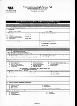


© Copyright 2026