
CRITERIA FOR AUTOMATED IDENTIFICATION OF STEREO IMAGE
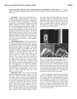
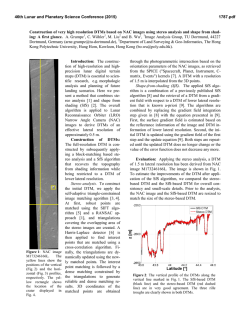
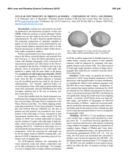
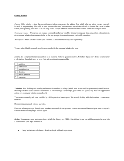
46th Lunar and Planetary Science Conference (2015)
2703.pdf
CRITERIA FOR AUTOMATED IDENTIFICATION OF STEREO IMAGE PAIRS. Kris J. Becker1, Brent A.
Archinal1, Trent M. Hare1, Randolph L. Kirk1,3, Elpitha Howington-Kraus1,4, Mark S. Robinson2, Mark R. Rosiek1,4, 1U.
S. Geological Survey, Astrogeology Science Center, 2255 N. Gemini Dr., Flagstaff, AZ, 86001 ([email protected]),
2
School of Earth and Space Exploration, Arizona State University, Tempe, AZ 85287; 3Emeritus; 4Retired.
Introduction: Stereo imaging forms the basis for much
of the 3-D terrain analysis conducted by researchers in
the planetary science community. Identifying the data
on which to conduct stereogrammetry can be
complicated and time-consuming [1-3]. While some
instrument teams maintain databases of deliberately
targeted stereo-pairs (e.g., Mars Reconnaissance Orbiter
(MRO) HiRISE [4] and Lunar Reconnaissance Orbiter
(LRO) Camera (LROC) [5]) there is no tool to locate
fortuitous stereo overlaps, especially for images from
different instruments.
Here we provide recommended methods and
constraints for locating stereo pairs. Many of these
recommendations can be tested using a new interactive
solution provided by the USGS via the web-based
Planetary Image Locator Tool (PILOT) application [6].
Overview: The main criteria to be used in
identifying stereo images include:
o Image overlap and similar spatial resolution.
o 3-D stereo imaging “strength” as computed from
emission and spacecraft azimuth angles.
o Illumination similarity as computed from incidence
and solar azimuth angles.
o Similar solar longitude (i.e. it is best to avoid
seasonal variations, such as differing frost patterns on
Mars).
o Compatible spectral wavelength range to achieve
similar contrast.
Recommendations are separated into two main
categories of evaluation: (1) individually identify all
candidate images that are suitable for stereo analysis
and (2) identify images with common surface coverage
that satisfy stereo pairing criteria. For both evaluation
categories, the range of acceptable values depends on
the intended use and thus most recommendations
provided below are not absolute. While we provide
specific “recommended” values, one should not take
these as necessarily the “optimal” value because there
can be a broad range of values that give similar quality
without a sharp optimum in usefulness.
Image Suitability for Stereo Analysis (1):
Generally, criteria for finding useful stereo image
candidates are generated for the center pixel of all
possible images, although a more robust solution might
compare only areas where images share common
surface coverage.
Incidence Angle. This angle is measured between
the local surface normal vector at the surface intercept
point (evaluated on a smooth representation of the
global shape) and the vector to the Sun (for radar
images, replace the sun vector with the radar source).
o Limits:
Between 40° and 65° depending on
smoothness (shadows to be avoided) [7].
o Recommended:
Nominally 50°
Emission Angle. The angle is measured between
the spacecraft-to-surface intercept vector and the local
surface normal vector at the intercept point (evaluated
on a smooth representation of the global shape). The
goal of this criterion is to exclude images with extreme
foreshortening (high emission angles for optical, low
for radar).
o Limits: Between 0° and the complement of the
maximum slope (conservatively 45°, greater for
smoother terrains) for optical images. Greater than
the slope (≥15° even for smooth surfaces) for radar.
o Recommended:
No recommendation.
Phase Angle (optional). Measured as the angle
between the spacecraft-to-surface intercept vector and
the illumination source (typically the Sun). Surface
appearance can vary with phase angle, especially at low
phase, so it may be useful to exclude low phase images.
o Limits: Between 5° and 120°.
o Recommended:
≥ 30°
Ground Sampling Distance (GSD). The width of
the pixels projected to the surface.
o Limits: GSD is chosen based on the desired GSD of
the output digital terrain model (DTM). Because
typical stereo matching methods do not produce
independent height estimates over distances smaller
than about 3 to 5 image pixels, the image GSD needs
to be 3 to 5 times smaller than the desired DTM
GSD.
o Recommended: Better than 1/3 of target DTM GSD.
Image-Pairs Suitability for Stereo (2): In general,
these comparative parameters are evaluated based on
the properties of the two images as measured at a
common ground point.
GSD Ratio. The ratio of the larger to the smaller
GSD of the two images at a common point.
o Limits: Image pairs with GSD ratios larger than 2.5
can be used but are not optimal, as details only seen
in the smaller scale image will be lost. If required,
images with ratios greater than ~2.5 should be
resampled to the GSD of the lower scale image.
o Recommended:
Between 1.0 and 2.5.
Strength of Stereo. The strength of a stereo pair is
measured as the angle between the emission vectors of
46th Lunar and Planetary Science Conference (2015)
the two images. This parameter can be generalized
(e.g., to cover cases in which both images are oblique)
in terms of the Parallax/Height Ratio (dp) computed as
shown in Figure 1 and can also be generalized to apply
to radar. Physically, dp represents the amount of
parallax difference that would be measured between an
object in the two images, for unit height.
o Limits: Between 0.1 (5°) and 1 (~45°).
o Recommended: 0.4 (20°) to 0.6 (30°).
Figure 1. Computation of dp
scazgnd = spacecraft azimuth ground
emi = emission angle
X component of parallax vector:
px = -tan(emi)*cos(scazgnd)
Y component of parallax vector:
py = tan(emi)*sin(scazgnd)
dp = !(!"1 − !"2)! + (!"1 − !"2)!
where 1 & 2 refer to the images of the pair.
Note: For radar, substitute cot(emi) for tan(emi).
Illumination
Compatibility.
Variations
in
illumination degrade matching to some extent even if
there are no shadows, but the effect becomes severe if
there are shadows and these differ. Compatibility of the
images can be measured in terms of the Shadow-Tip
Distance (dsh) computed as shown in Figure 2. This is
defined as the distance between the tips of the shadows
in the two images for a hypothetical vertical post of unit
height. The "shadow length" describes the shadow of a
hypothetical pole so it applies whether there are
actually shadows in the image or not. It's a simple and
consistent geometrical way to quantify the difference in
illumination. This quantity is computed analogously to
dp. These criteria should also apply to radar, but
appropriate limits have not been determined.
o Limits: 0 to 2.58.
o Recommended: 0
Delta Solar Azimuth Angle (optional). In practice,
dsh alone does not guarantee similar illumination. The
absolute difference in solar azimuth angle between
stereo pairs can be optionally constrained.
o Limits: 0° to 100°.
o Recommended: ≤20°
Common Image Stereo Overlap. Amount of
common surface coverage between the stereo pair
images expressed as a percentage of the smaller area to
the larger. Note that stereo convergence obtained by
targeting some images off-nadir to increase overlap
does not weaken the stereo.
o Limits:
Between 30% and 100%.
o Recommended: 50% to 100%.
2703.pdf
Spectral Range. This is the image color as
determined by band, filter, or wavelength. Substantial
differences in wavelength may degrade stereo
matching.
o Limits:
This is very dependent on the filters, the
target, and how colorful the target is.
o Recommended: Same or within a spectral difference
which is instrument and target dependent.
Figure 2. Computation of dsh
sunazgnd = solar azimuth ground
inc = incidence angle
X component of solar vector:
shx = -tan(inc)*cos(sunazgnd)
Y component of solar vector:
shy = tan(inc)*sin(sunazgnd)
dsh = !(!ℎ!1 − !ℎ!2)! + (!ℎ!1 − !ℎ!2)!
where 1 & 2 refer to the images of the pair.
Application of Method: The incidence, emission,
phase and GSD limits are applied to winnow out nonstereo image candidates. Image lists that satisfy these
individual image suitability requirements are then used
to find stereo image sets. Stereo image sets are
determined by finding all complements that satisfy the
stereo paring constraints first for Common Image Stereo
Overlap and then for the constraints on GSD Ratio,
Strength of Stereo and Illumination Compatibility. The
output results are a set of stereo complement images
(one or more) for each image in the seed list (including
the seed image, of course), preferably ranked by the dp
and dsh criteria. For flexibility, all search parameters
(for single image and image pairs) should be enterable
as a range of values, allowing the same value in the
upper and lower limit to winnow on a single value.
Acknowledgements: We would like to thank the
MESSENGER, HiRISE and HRSC projects and the
LRO Participating Scientist program for funding and
support of this work.
References: [1] Cook, A., et al. 1996, Planet.
Space Sci., 44, no. 10, 1135-1148. [2] Kirk, R. L., et al.
2008, JGR, 113, E00A24, doi:10.1029/2007JE003000.
[3] Kirk, R. L., et al. 1999, LPS XXX, Abstract #1857.
[4] Mattson, S. et al (2011) LPSC LXII Abstract #1558.
[5] Burns, K.N., et al (2012) ISPRS XXII, v. XXXIXB4-483. [6] Balien., M. B., 2015, this conference. [7]
Kirk R. L. et al (2015) this conference.

© Copyright 2026