
ACE732E - ACE Technology
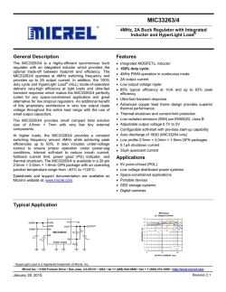
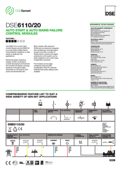
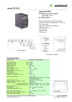
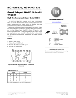
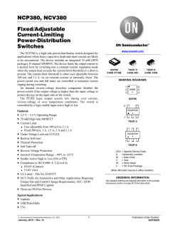
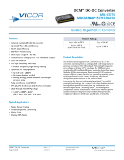
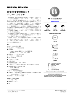
ACE732E
6V/3.5A, Fast Response, Step-Down Converter
Description
ACE732E belongs to a new breed of high frequency synchronous Step-Down converter that combines the
advantages of voltage mode control and Constant-On-Time control. Its adaptive Constant-On-Time control
dynamically changes switch on time to achieve a constant switching frequency. It does not have the
minimum on-time constrain normally a fixed-frequency current mode Step-down requires, allowing it to go
down to very low duty ratio without affecting loop stability. The voltage mode nature of ACE732E also
provides a more superior load transient response and a seamless transition from PFM to PWM modes.
ACE732E is capable of supplying output with current up to 3.5A at 1.2V output. All these features make
ACE732E an excellent choice for ARM based CPU power supply.
Features
•
•
•
•
•
•
•
Adaptive COT control
Up to 95% Efficiency
Up to 91% Efficiency for
low output voltage
Up to 3.5A Max Output current
Feedback voltage 0.45V
Excellent load transient response
DFN2X2-8L Package
Application
•
•
•
•
ARM based CPUs
Tablet, MID
Smart Phone
Smart Set-Top Box, OTT
Absolute Maximum Rating
Parameter
Value
VIN Voltage
-0.3V~6V
All Other Pin Voltage
VIN-0.3V~VIN0.3V
SW to ground current
Internally limited
Operating Temperature Range
-40°C~85°C
Storage Temperature Range
-55°C~150°C
Thermal Resistance
θJA
75
°C /W
Note: Exceed these limits to damage to the device. Exposure to absolute maximum rating conditions may affect device reliability.
VER 1.1
1
ACE732E
6V/3.5A, Fast Response, Step-Down Converter
Typical Application
ACE732E
Typical Application Circuit of 1.2V Output
Packaging Type
EN
VIN
PGND
SW
AGND
NC
FB
VOS
DFN2x2-8L
DFN2x2-8
Description
Function
1
EN
PGND
Enable pin for the IC. Drive this pin to high to enable the part, low to disable
2
3
AGND
4
FB
5
VOS
6
NC
7
SW
8
VIN
Power Ground. The ground of internal power NMOS. Bypass with a 22μF
ceramic capacitor to VIN
Analog Ground. To keep this ground free from noise by connecting a 10nF
ceramic capacitor to VIN. Do not short his pin to PGND directly in PCB,
but through a PCB trace to connect the 2 GND together.
Feedback Input. Connect an external resistor divider from the output to
FB and GND to set the output to a voltage between 0.45V and VIN
Output voltage sense pin, to be connected to the output node of regulator.
Not connected. Please do leave this pin float.
Inductor Connection. Connect an 1uH inductor Between SW and the
regulator output.
Supply Voltage. Bypass with a 22μF ceramic capacitor to PGND and 10nF
to AGND.
VER 1.1
2
ACE732E
6V/3.5A, Fast Response, Step-Down Converter
Ordering information
ACE732E XX XX + H
Halogen - free
Pb - free
DN: DFN2*2-8L
ADJ: Adjustable Voltage
Block Diagram
Electrical Characteristics
VIN=VEN=5, TA=25°C
Parameter
Input Voltage Range
Conditions
Min
Typ
2.6
Max
Unit
5.5
V
Input UVLO
Rising, Hysteresis=250mV
2.15
V
Input OVP
6.25
V
Input Supply Current
Rising, Hysteresis=200mV
VFB =0.5V, Device Not Switching
50
uA
Input Shutdown Current
EN=GND
0.1
1
uA
0.45
0.464
V
FB Feedback
Voltage
0.436
FB Input Current
0.01
Output Voltage Range
0.45
Load Regulation
Line Regulation
VIN =3V to 4V
uA
VIN
0.18
V
%A
0.1
%V
VER 1.1
3
ACE732E
6V/3.5A, Fast Response, Step-Down Converter
Switching Frequency
1.0
1.5
2.0
MHz
PMOS Switch On Resistance
ISW =200mA
120
mΩ
NMOS Switch On Resistance
ISW =200mA
60
mΩ
PMOS Switch Current Limit
VIN =5V
4.5
A
SW Leakage Current
VIN=5.5V,VSW=0 or 5.5V,EN= GND
4
EN Input Current
EN Input Low Voltage
uA
1
uA
0.4
V
EN Input High Voltage
Thermal Shutdown
10
1.5
Rising, Hysteresis =20°C
155
V
°C
Typical Characteristics
(Typical values are at TA=25°C unless otherwise specified)
Efficiency Vs Iout, Vout=3.3V
Efficiency Vs Iout, Vout=1.2V
Output Voltage Vs Iout, Vout=3.3V
Output Voltage Vs Iout, Vout=1.2V
VER 1.1
4
ACE732E
6V/3.5A, Fast Response, Step-Down Converter
Vout
Vs. Vin, Iout=0
Switching Frequency Vs. Ambient Temperature
Switching Waveform: VIN=5V, VOUT=1.2V, IOUT=0 mA
Iq Vs. Temperautre, Iout=0 and In Switching
Maximum Iout Vs. Ambient Temperature
Switching Waveform: VIN=5V, VOUT=1.2V, IOUT= 3A
VER 1.1
5
ACE732E
6V/3.5A, Fast Response, Step-Down Converter
Transient Response: VIN=5V, VOUT=1.2V, IOUT=0.3-3A
Output Short Response: VIN=5V, VOUT=1.2V, Output short to GND
FUNCTIONAL DECRIPTIONS
ACE732E belongs to a new breed of high frequency synchronous Step-Down converter that combines the
advantages of voltage mode control and Constant On time control. Its adaptive Constant-On-Time control
dynamically changes switch on time to achieve a constant switching frequency. It does not have the
minimum on-time constrain normally a fixed-frequency current mode Step-down requires, allowing it to go
down to very low duty ratios without affecting loop stability. The voltage mode nature of ACE732E also
provides a more superior load transient response as well as a seamless transition from PFM to PWM modes.
It can also operate up to 100% duty. It has a cycle by cycle current limit and a hiccup mode that protects
against dead-short condition. It includes soft-start, UVLO and thermal shutdown protection.
Adaptive Constant On-Time Control
ACE732E uses an adaptive Constant-On-Time control scheme that the ON time is dynamically adjusted
according to VIN and VOUT so to achieve a nearly constant switching frequency. This control scheme
provides simpler compensation and superior transient response over traditional constant frequency current
mode control, while still maintaining the advantage of switching at a constant frequency at about 1.5MHz. It
also provides a seamless transition from PFM to PWM that normally a constant frequency current mode
control scheme is hard to achieve. Further mode, because it is a COT control scheme, the system can
achieve high step-down ratio at ease, because lower constrain on the minimum on- time requirement
existing in constant frequency scheme.
100% Duty operation
ACE732E can operate at 100% duty cycle under dropout condition for high efficiency purpose.
Current Limit and Short-Circuit protection
ACE732E employs a cycle-by-cycle peak current limit and it also has a hiccup mode that protects the circuit
during dead-short condition. When the dead-short condition is removed, the IC goes back to normal
operation.
Soft-start
ACE732E has an internal soft-start circuitry to reduce supply inrush current during startup conditions.
When the device exits under-voltage lockout (UVLO), shutdown mode, or restarts following a
VER 1.1
6
ACE732E
6V/3.5A, Fast Response, Step-Down Converter
thermal-overload event, the l soft-start circuitry slowly ramps up current available at SW.
UVLO and Thermal Shutdown
If IN drops below UVLO threshold, the UVLO circuit inhibits switching. Once IN rises above ULVO
threshold, the UVLO clears, and the soft-start sequence activates. Thermal-overload protection limits total
power dissipation in the device. When the junction temperature exceeds TJ=+155°C, a thermal sensor
forces the device into shutdown, allowing the die to cool. The thermal sensor turns the device on again after
the junction temperature cools by 15°C, resulting in a pulsed output during continuous overload conditions.
Following a thermal-shutdown condition, the soft-start sequence begins.
Design Procedure
Setting Output Voltages
Output voltages are set by external resistors. The FB threshold is 0.45V.
RTOP = RBOTTOM x [(VOUT / 0.45) - 1]
Inductor Selection
The peak-to-peak ripple is limited to 30% of the maximum output current. This places the peak current far
enough from the minimum overcurrent trip level to ensure reliable operation while providing enough current
ripples for the current mode converter to operate stably.
LIDEAL=(VIN(MAX)-VOUT)/IRIPPLE*DMIN*(1/FOSC)
Output Capacitor Selection
The output capacitor keeps output ripple small and ensures control-loop stability. The output capacitor must
also have low impedance at the switching frequency. Ceramic, or a MLCC capacitors are suitable, with
ceramic exhibiting the lowest ESR and high-frequency impedance. Output ripple with a ceramic output
capacitor is approximately as follows:
VRIPPLE = IL(PEAK)[1 / (2π x fOSC x COUT)]
If the capacitor has significant ESR, the output ripple component due to capacitor ESR is as follows:
VRIPPLE(ESR) = IL(PEAK) x ESR
Input Capacitor Selection
The input capacitor in a DC-to-DC converter reduces current peaks drawn from the battery or other input
power source and reduces switching noise in the controller. The impedance of the input capacitor at the
switching frequency should be less than that of the input source so high-frequency switching currents do not
pass through the input source. The output capacitor keeps output ripple small and ensures control-loop
stability.
PCB LAYOUT
The ACE732E employs a sophisticated control scheme to achieve the fast response and other superior
performances. So the PCB layout is recommended to strictly follow the proposed way shown below. The Cin
(22uF) and Cout (22uF or 10uF x 2) are always to be placed closest to ACE732E. The Cin1 (10nF) is also
require to be connected to AGND (not PGND) to filter out the switching noise. Please don’t short Pin2
(PGND) and Pin3 (AGND) directly, but through a PCB trace, as what’s shown below.
Please contact ACE engineers for confirmation if one needs to change the PCB layout.
VER 1.1
7
ACE732E
6V/3.5A, Fast Response, Step-Down Converter
VER 1.1
8
ACE732E
6V/3.5A, Fast Response, Step-Down Converter
Packing Information
DFN2x2-8L
Symbol
A
A1
A3
b
D
E
D2
E2
e
K
L
R
Min.
0.70
̅—
0.15
1.90
1.90
0.50
1.10
0.40
0.20
0.30
0.09
Dimensions in millimeters
Nom.
0.75
0.02
0.20REF
0.20
2.00
2.00
0.60
1.20
0.50
—
0.35
—
Max.
0.80
0.05
0.25
2.10
2.10
0.70
1.30
0.60
—
0.40
—
VER 1.1
9
ACE732E
6V/3.5A, Fast Response, Step-Down Converter
Notes
ACE does not assume any responsibility for use as critical components in life support devices or systems
without the express written approval of the president and general counsel of ACE Electronics Co., LTD. As
sued herein:
1. Life support devices or systems are devices or systems which, (a) are intended for surgical implant into
the body, or (b) support or sustain life, and shoes failure to perform when properly used in accordance
with instructions for use provided in the labeling, can be reasonably expected to result in a significant
injury to the user.
2. A critical component is any component of a life support device or system whose failure to perform can be
reasonably expected to cause the failure of the life support device or system, or to affect its safety or
effectiveness.
ACE Technology Co., LTD.
http://www.ace-ele.com/
VER 1.1
10


© Copyright 2026