
Download - TDK Europe
EPCOS Product Profile 2013
Power Factor Correction
Power Quality Solutions
www.epcos.com
Contents
Power Quality Solutions
Preview
PFC capacitor series overview
PQS key components overview
Important notes
PFC capacitors
¼ PhaseCap Premium (230 … 800 V, 5.0 … 33 kvar)
¼ PhaseCap Compact (230 … 1000 V, 5.0 … 33 kvar)
¼ PhaseCap HD (400 … 525 V, 40 … 60 kvar)
¼ PhiCap (230 … 525 V, 0.5 … 30 kvar)
¼ MKV capacitors (400 … 800 V, 4.2 … 30 kvar)
PF controllers and measuring devices
¼ BR604, BR6000, BR7000, BR7000-T, BR7000-I series and BR7000-SOFT
¼ Multi Measuring Interfaces
¼ Grid analysis tool MC7000-3
Switching devices
¼ Capacitor contactors
¼ Thryristor modules for dynamic PFC TSM series
Reactors
¼ Reactors – Antiresonance harmonic filter
¼ Discharge reactor
Fundamentals of Power Factor Correction
¼ Components for Power Factor Correction
¼ Standard values: Selection tables for cables, cable cross sections and fuses
¼ Calculation table for reactive power demand (Qc)
¼ Individual PFC for motors
¼ Individual PFC for transformers
¼ Detuned PFC in general
¼ Detuned PFC: Important facts and instructions
¼ Component selection tables for detuned PFC
¼ Dynamic PFC: Important facts and instructions
¼ Component selection tables for dynamic PFC
¼ PFC basic formulas
Cautions
Addresses
2
3
6
8
10
11
18
24
27
34
38
52
54
56
59
63
66
67
68
71
73
74
75
76
77
78
82
83
86
89
94
© EPCOS AG 2013
Preview
General
How reactive power is generated
The increasing demand of electrical
power and the awareness of the
necessity of energy saving is very up
to date these days. Also the awareness of power quality is increasing,
and power factor correction (PFC) and
harmonic filtering will be implemented
on a growing scale. Enhancing power
quality – improvement of power factor
– saves costs and ensures a fast
return on investment. In power distribution, in low- and medium-voltage
networks, PFC focuses on the power
flow (cos ϕ) and the optimization of
voltage stability by generating reactive
power – to improve voltage quality and
reliability at distribution level.
Every electric load that works with
magnetic fields (motors, chokes,
transformers, inductive heating, arc
welding, generators) produces a varying degree of electrical lag, which is
called inductance. This lag of inductive
loads maintains the current sense (e.g.
positive) for a time even though the
negative-going voltage tries to reverse
it. This phase shift between current
and voltage is maintained, current and
voltage having opposite signs. During
this time, negative power or energy
is produced and fed back into the
network. When current and voltage
have the same sign again, the same
amount of energy is again needed to
build up the magnetic fields in inductive loads. This magnetic reversal
energy is called reactive power.
In AC networks (50/60 Hz) such a
process is repeated 50 or 60 times a
second. So an obvious solution is to
briefly store the magnetic reversal
energy in capacitors and relieve the
network (supply line) of this reactive
energy. For this reason, automatic
© EPCOS AG 2013
reactive power compensation systems
(detuned/conventional) are installed for
larger loads like industrial machinery.
Such systems consist of a group of
capacitor units that can be cut in and
cut out and which are driven and
switched by a power factor controller.
Apparent power S = √P² + Q²
Active power P = S * cos ϕ
Reactive power Q = S * sin ϕ
With power factor correction the apparent power
S can be decreased by reducing the reactive
power Q.
Reactive Power [kvar]
Q2 = S 2 — P 2
Q2
QC
Q1
ϕ1
P
ϕ2
S2
S1
Apparent Power [kVA]
S2 = P2 + Q2
Active Power [kW]
P2 = S2 — Q2
3
Preview
Power factor
Low power factor (cos ϕ)
Low cos ϕ results in
¼ higher energy consumption and
costs,
¼ less power distributed via the
network,
¼ power loss in the network,
¼ higher transformer losses,
¼ increased voltage drop in power
distribution networks.
Power factor improvement
Power factor improvement can be
achieved by
¼ compensation of reactive power
with capacitors,
¼ active compensation – using
semiconductors,
¼ overexcited synchronous machine
(motor/generator).
Uninterruptible Power Supply
(optional)
Tuned
harmonic
filters
(Aluminum electrolytic
or film capacitors)
¼ individual or fixed compensation
(each reactive power producer is
individually compensated),
¼ group compensation (reactive power
producers connected as a group
and compensated as a whole),
¼ central or automatic compensation
(by a PFC system at a central point),
¼ mixed compensation.
Power Factor Correction (PFC)
and Harmonic Filtering
EMC filter
C
DC link
Types of PFC
(detuned or conventional)
Linear load
with fixed
PFC
Dynamic
PFC
systems
Passive
harmonic
filters
Active
harmonic
filters
Frequency converter
Overvoltage
protection
M
3~
Overvoltage
protection
Overvoltage
protection
Overvoltage
protection
C
Output filter
4
Overvoltage
protection
Charging
resistor
EMC filter
250/350/
550 Hz
M
3~
(detuned
PFC
systems)
© EPCOS AG 2013
Preview
I
U
U
I
Linear loads:
voltage was followed
by current.
Non linear load produce
non sinusoidal currents when
connected to sinusoidal voltage.
PQS strategy
Along with the emerging demand for
power quality and a growing awareness of the need for environmental
protection, the complexity in the energy market is increasing: users and
decision-makers are consequently
finding it increasingly difficult to locate
the best product on the market and to
make objective decisions. It is in most
cases not fruitful to compare catalogs
and data sheets, as many of their
parameters are identical in line with
the relevant standards. Thus operating
times are specified on the basis of
tests under laboratory conditions that
may differ significantly from the reality
in the field. In addition, load structures
© EPCOS AG 2013
have changed from being mainly linear
in the past to non-linear today. All this
produces a clear trend: the market
is calling increasingly for customized
solutions rather than off-the-shelf
products. This is where Power Quality
Solutions come into the picture. It offers all key components for an effective PFC system from a single source,
together with:
These are the cornerstones on which
Power Quality Solutions are built. On
the basis of this strategy, EPCOS is
not only the leading manufacturer of
power capacitors for PFC applications
but also a PQS supplier with a century
of field experience, reputation and
reliability.
¼ Application know-how
¼ Technical skills
¼ Extensive experience in the field of
power quality improvement
¼ A worldwide network of partners
¼ Continuous development
¼ Sharing of information
5
PFC Capacitor Series Overview
PFC capacitor series for power factor correction and detuned filter
Parameter
PhaseCap Premium
PhaseCap Compact
Power
QR
Rated voltage VR
Inrush current IS
Temperature
class
5.0 … 33.0 kvar
230 … 800 V AC
up to 300 · IR
–40/D:
max. temp. +55 °C
max. mean 24 h = +45 °C
max. mean 1 year = +35 °C
lowest temperature = –40 °C
5.0 … 33.0 kvar
230 … 1000 V AC
up to 400 · IR
–40/60:
max. temp. +60 °C
max. mean 24 h = +45 °C
max. mean 1 year = +35 °C
lowest temperature = –40 °C
–40/C:
max. temp. +50 °C
max. mean 24 h = +40 °C
max. mean 1 year = +30 °C
lowest temperature = –40 °C
< 0.2 W/kvar
< 0.45 W/kvar
95%
triple (self-healing, overpressure
disconnector, dry technology)
inert gas
up to 180 000 h (temp. class –40/C)
up to 130 000 h (temp. class –40/D)
optimized capacitor safety
terminal
< 0.2 W/kvar
< 0.45 W/kvar
95%
dual (self-healing, 3-phase
overpressure disconnector)
semi-dry biodegradable resin
up to 200 000 h (temp. class –40/C)
up to 150 000 h (temp. class –40/60)
optimized capacitor safety
terminal (IP20), (VDE 0106
part 100), for current and
connection cable details and
terminal type/capacitor type
association see terminal drawings
and capacitor type list
natural or forced
aluminum/cylindrical
IP20, indoor mounting, optionally
with terminal cap for IP54 (for
diameter 116 and 136 mm)
IEC 60831-1+2, EN 60831-1+2
Losses:
– Dielectric
QL
– Total1)
QL
Max. humidity Hrel
Safety
Impregnation
Mean life
expectancy
Connection
1)
6
tLD (co)
Cooling
Case/shape
Enclosure
natural or forced
aluminum/cylindrical
IP20, indoor mounting, optionally
with terminal cap for IP54
Standard
IEC 60831-1+2, UL 810 5th edition,
cUL file # E238746 (up to 690 V),
GOST
Ordering code
B25667C*
B25673A*
B25673S*
Page
11
18
Without discharge resistor
Please read Important notes on page 10 and Cautions on page 89–93.
© EPCOS AG 2013
PFC Capacitor Series Overview
PhaseCap HD
PhiCap
MKV
40.0 ... 60.0 kvar
400 ... 525 V AC
up to 300 · IR
–40/D:
max. temp. +55 °C
max. mean 24 h = +45 °C
max. mean 1 year = +35 °C
lowest temperature = –40 °C
0.5 ... 30.0 kvar
230 ... 525 V AC
up to 200 · IR
–40/D:
max. temp. +55 °C
max. mean 24 h = +45 °C
max. mean 1 year = +35 °C
lowest temperature = –40 °C
4.2 … 30.0 kvar
400 … 800 V AC
up to 500 · IR
–40/70:
max. temp. +70 °C
max. mean 24 h = +55 °C
max. mean 1 year = +45 °C
lowest temperature = –40 °C
< 0.2 W/kvar
< 0.45 W/kvar
95%
triple (self-healing, overpressure
disconnector, dry technology)
inert gas
up to 180 000 h (temp. class –40/C)
up to 130 000 h (temp. class –40/D)
SIGUT™, block-type safety terminal
< 0.2 W/kvar
< 0.45 W/kvar
95%
dual (self-healing, overpressure
disconnector)
biodegradable soft resin, semi-dry
up to 135 000 h (temp. class –40/C)
up to 100 000 h (temp. class –40/D)
B32340 / B32343 series:
fast-on terminals
B32344 series:
optimized capacitor safety terminal,
block-type
< 0.2 W/kvar
< 0.35 W/kvar
95%
dual (self-healing, overpressure
disconnector)
oil
up to 300 000 h
at temperature class –40/D
SIGUT™, block-type
safety terminal
natural or forced
aluminum/cylindrical
IP20
natural or forced
aluminum/cylindrical
IP00 for B32340/B32343 series;
optionally IP54 for B32344 series
with terminal cap
IEC 60831-1+2, UL 810 5th edition
cUL file # E106388
CSA file # C22.2 No190 MC # 236094,
(up to ø 85 mm), GOST
B32340C*
B32343C*
B32344E*
27
natural or forced
aluminum/cylindrical
IP20, optionally IP54 with terminal cap
IEC 60831-1+2,
UL 810 5th edition
GOST
B25669*
24
© EPCOS AG 2013
IEC 60831-1+2
EN 60831-1+2
GOST
B25836B*
34
Please read Important notes on page 10 and Cautions on page 89–93.
7
PQS Key Components Overview
PF controller BR604, BR6000 V6.0 and BR7000
Parameter
BR604
BR6000-R
BR6000-T
BR7000/BR7000-HD
BR7000-T
BR7000-I
BR7000-I/S485
Supply voltage
Measurement
voltage range
Measurement
current
Frequency
Sensivity
230 V AC
230 V AC
X/5 or X1/A
selectable
50 and 60 Hz
50 mA/10 mA
110 … 230 V AC ±15%
30 … 525 V AC (L-N) 3 · 440 V AC (L-N),
or (L-L)
3 · 50 … 760 V AC (L-L)
X/5 or X1/A
3 x X:5A/X1A
selectable
selectable
30 … 440 V AC (L-N),
50 … 760 V AC (L-L)
X:5A/X1A
selectable
Output stages
Relay outputs
Transistor outputs
Interface
Ordering code
BR604
BR6000-R6
BR6000-R6/HD
BR6000-R12
BR6000-R12/HD
BR6000-T6
BR6000-T12
BR6000-R12/S485
BR6000-R12/S485/HD
BR6000-T6R6
BR6000-T6R6/S485
BR6000-T12/S485
BR7000
BR7000-HD
BR7000-T
BR7000-T/HD
BR7000-I
BR7000-I/S485
Page
4
6
6
12
12
–
–
12
12
6
6
–
15
15
–
–
12 + 1
12 + 1
38
–
–
–
–
–
6
12
–
–
6
6
12
–
–
15
15
–
–
38
–
–
–
–
–
–
–
RS485
RS485
–
RS485
RS485
2 x RS485
2 x RS485
2 x RS485
2 x RS485
–
RS485
42
B44066R6004E230
B44066R6006E230
B44066R6506E230
B44066R6012E230
B44066R6512E230
B44066R6106E230
B44066R6112E230
B44066R6412E230
B44066R6612E230
B44066R6066E230
B44066R6466E230
B44066R6412E231
B44066R7415E230
B44066R7515E230
B44066R7615E230
B44066R7715E230
B44066R7012E230
B44066R7112E230
45
BR604
BR6000
BR7000
Multi measuring interfaces
Parameter
MMI6000
MMI7000
Operating voltage
Measurement
voltage
Measurement
current
Frequency
Power consumption
Ordering code
Page
230 V AC
230 V AC, single-phase
X/5 or X /1 selectable
110 … 230 V AC
3 · 30 … 440 V AC (L-N)
3 · 50 … 760 V AC (L-L), three-phase
Three phase X:1A / X:5A
50/60 Hz
< 4 VA
B44066M6 … E230
52
50/60 Hz
< 5 VA
B44066M7… E230
52
MMI6000
MMI7000
8
Please read Important notes on page 10 and Cautions on page 89–93.
© EPCOS AG 2013
PQS Key Components Overview
Grid analysis tool MC7000-3
1)
Parameter
MC7000-3
Operating voltage
110 … 230 V AC ±15%
Max. measuring
voltage1)
(3-phase)
3 · 30 … 440 V AC (L-N), 50/60 Hz
3 · 50 … 760 V AC (L-L), 50/60 Hz
Max. measuring
current
(3-phase)
30, 300, 3000 A
Frequency
50/60 Hz
Ordering code
B44066M7777E230
Page
54
incl. all tolerances and voltages
Switching devices
Parameter
Capacitor contactors
Voltage
230 … 690 V
Output range
12.5 … 100 kvar
Frequency
De-tuning
50 /60 Hz
Ordering code
B44066S…J230/J110
for all PFC systems
B44066S…N230/N110
for detuned PFC systems only
56
Page
© EPCOS AG 2013
Thyristor modules
Thyristor switch for dynamic
PFC systems
TSM-LC-I: 230 … 525 V
TSM-LC: 3 · 400 V
TSM-HV: 3 · 690 V
TSM-LC-I: 10 … 22 kvar,
depending on voltage
TSM-LC: 10 … 200 kvar
TSM-HV: 50 and 200 kvar
50/60 Hz
suitable for detuned
and conventional systems
TSM-LC-I: B44066T1022E520
TSM-LC: B44066T…E402
TSM-HV: B44066T…E690
59
Reactors – Antiresonance
harmonic filter
400 and 440 V
10 … 100 kvar
50 or 60 Hz
factor: 5.67%, 7%, 14%
B44066D*
63
Please read Important notes on page 10 and Cautions on page 89–93.
9
Important Notes
The following applies to all products named in this
publication:
1. Some parts of this publication contain statements about
the suitability of our products for certain areas of application. These statements are based on our knowledge
of typical requirements that are often placed on our products in the areas of application concerned. We nevertheless expressly point out that such statements cannot be
regarded as binding statements about the suitability
of our products for a particular customer application.
As a rule, EPCOS is either unfamiliar with individual customer applications or less familiar with them than the
customers themselves. For these reasons, it is always ultimately incumbent on the customer to check and decide
whether an EPCOS product with the properties described
in the product specification is suitable for use in a particular customer application.
2. We also point out that in individual cases, a malfunction of electronic components or failure before the
end of their usual service life cannot be completely
ruled out in the current state of the art, even if they are
operated as specified. In customer applications requiring a very high level of operational safety and especially in
customer applications in which the malfunction or failure
of an electronic component could endanger human life or
health (e.g. in accident prevention or life-saving systems),
it must therefore be ensured by means of suitable design
of the customer application or other action taken by the
customer (e.g. installation of protective circuitry or
redundancy) that no injury or damage is sustained by third
parties in the event of malfunction or failure of an electronic component.
3. The warnings, cautions and product-specific notes
must be observed.
10
4. In order to satisfy certain technical requirements, some of
the products described in this publication may contain
substances subject to restrictions in certain jurisdictions (e.g. because they are classed as hazardous).
Useful information on this will be found in our Material
Data Sheets on the Internet (www.epcos.com/material).
Should you have any more detailed questions, please contact our sales offices.
5. We constantly strive to improve our products. Consequently, the products described in this publication
may change from time to time. The same is true of the
corresponding product specifications. Please check
therefore to what extent product descriptions and specifications contained in this publication are still applicable
before or when you place an order.
We also reserve the right to discontinue production
and delivery of products. Consequently, we cannot
guarantee that all products named in this publication will
always be available.
The aforementioned does not apply in the case of
individual agreements deviating from the foregoing for
customer-specific products.
6. Unless otherwise agreed in individual contracts, all
orders are subject to the current version of the “General Terms of Delivery for Products and Services in
the Electrical Industry” published by the German
Electrical and Electronics Industry Association (ZVEI).
7. The trade names EPCOS, BAOKE, Alu-X, CeraDiode,
CeraLink, CSMP, CSSP, CTVS, DeltaCap, DigiSiMic,
DSSP, FilterCap, FormFit, MiniBlue, MiniCell, MKD,
MKK, MLSC, MotorCap, PCC, PhaseCap, PhaseCube,
PhaseMod, PhiCap, SIFERRIT, SIFI, SIKOREL, SilverCap,
SIMDAD, SiMic, SIMID, SineFormer, SIOV, SIP5D,
SIP5K, ThermoFuse, WindCap are trademarks registered or pending in Europe and in other countries.
Further information will be found on the Internet at
www.epcos.com/trademarks.
Please read Important notes on page 10 and Cautions on page 89–93.
© EPCOS AG 2013
PhaseCap Premium PFC Capacitors
Gas-impregnated ¼ Dry type ¼ Concentric winding ¼ Wavy cut ¼ Triple safety system
General
PhaseCap capacitors in cylindrical
aluminum cases have been designed for power factor correction
in low-voltage applications.
The MKK (metalized plastic compact) AC series is intended to
increase packing density per bank
and cut component costs.
Loads like motors and transformers consume active power as well
as reactive power.
Improved thermal response and
simplified installation are advantages of the cylindrical aluminum
case.
Generators, supply cables and
other electrical distribution equipment, in turn, should be relieved of
reactive power.
Applications
Features
¼ Automatic PFC equipment,
capacitor banks
¼ Individual fixed PFC (e.g. motors,
transformers, lighting)
¼ Group fixed PFC
¼ Tuned and detuned capacitor banks
¼ Dynamic PFC
¼ Compact design in cylindrical
aluminum can with stud
¼ Concentric winding
¼ MKK-technology with wavy cut and
heavy edge
¼ Voltage range 230 V … 800 V
¼ Output range 5.0 kvar … 33 kvar
Electrical
¼ Long life expectancy
¼ High pulse current withstand
capability
Safety
¼ Self-healing
¼ Overpressure disconnector
¼ Shock hazard protected terminals
¼ Longterm approved
¼ cUL approval up to 690 V
¼ Ceramic discharge resistor
pre-mounted
Environmental
¼ Dry design, inert gas
¼ No oil leakage
Mechanical and maintenance
¼ Reduced mounting costs
¼ Maintenance-free
¼ Highest packing density thanks to
compact dimensions
© EPCOS AG 2013
Please read Important notes on page 10 and Cautions on page 89–93.
11
PhaseCap Premium PFC Capacitors
Gas-impregnated ¼ Dry type ¼ Concentric winding ¼ Wavy cut ¼ Triple safety system
Technical data and limit values
Standards IEC 60831-1+2, EN 60831-1+2, UL 810 5th edition
Overvoltage
Vmax
VR + 10% (up to 8 h daily) / VR + 15% (up to 30 min daily) /
VR + 20% (up to 5 min daily) / VR + 30% (up to 1 min daily)
Overcurrent
Imax
Up to 1.6 · IR including combined effects of harmonics,
overvoltages and capacitance tolerance
Inrush current
IS
up to 300 · IR
Losses:
– Dielectric
– Total *
< 0.2 W/kvar
< 0.45 W/kvar
Rated frequency
f
Capacitance tolerance
50/60 Hz
– 5% / +10%
Test voltage, terminal / terminal
VTT
2.15 · VR1, AC, 10 s
Test voltage, terminal / case
VTC
up to VR ≤ 660 V: 3000 V AC, 10 s; above VR = 660 V: 6000 V AC, 10 s
Mean life expectancy
t LD(Co)
up to 180 000 h (temp. class –40/C); up to 130 000 h (temp. class –40/D)
Ambient temperature
–40/D; max. temp. +55 °C; max. mean 24 h = +45 °C;
max. mean 1 year = +35 °C; lowest temperature = –40 °C
Cooling
natural or forced
Humidity
Hrel
max. 95%
Altitude
max. 4000 m above sea level
Mounting position
upright / horizontal
Mounting and grounding
threaded M12 stud on bottom of case
Safety
dry technology, overpressure disconnector, self-healing, maximum
allowed fault current 10 000 A in accordance with UL 810 standard
Discharge device
ceramic discharge resistor pre-mounted up to 690 V;
external discharge module for > 690 V
Case
extruded aluminum can
Enclosure
IP20, indoor mounting (optionally with terminal cap for IP54)
Dielectric
polypropylene film
Impregnation
inert gas, Nitrogen (N2)
Terminals
optimized capacitor safety terminal with electric shock protection (IP20),
(VDE 0106 part 100), max. 25 mm2 cable cross-section, max. current 80 A
Certification
cUL file # E238746 up to 690 V, GOST
Number of switching operations
max. 7500 switchings per year
* Without discharge resistor
12
Please read Important notes on page 10 and Cautions on page 89–93.
© EPCOS AG 2013
PhaseCap Premium PFC Capacitors
Gas-impregnated ¼ Dry type ¼ Concentric winding ¼ Wavy cut ¼ Triple safety system
Three-phase capacitors
Type
50 Hz
Output
kvar
60 Hz
IR
A
Output
kvar
IR
A
CR
dxh
Weight
µF
mm
kg
Ordering code
Packing unit*
Rated voltage 230 V AC, 50 / 60 Hz, delta connection
MKK230-D-5.0-01
5.0
13
6.0
16
3 · 100
116 x 164
1.3
B25667C3297A375
6
MKK230-D-7.5-01
7.5
MKK230-D-10.4-01
10.4
19
9.0
23
3 · 150
116 x 164
1.3
B25667C2457A375
6
26
12.5
31
3 · 209
116 x 164
1.5
B25667C2627A375
MKK230-D-12.5-013)
12.5
6
31
15.0
37
3 · 251
116 x 200
1.7
B25667C2757A375
4
Rated voltage 400 V AC, 50 / 60 Hz, delta connection
MKK400-D-5.0-01
5.0
7
6.0
9
3 · 32
116 x 164
1.1
B25667C5966A375
6
MKK400-D-7.5-01
7.5
11
9.0
13
3 · 50
116 x 164
1.2
B25667C3147A375
6
MKK400-D-10.0-01
10.0
14
12.0
17
3 · 64
116 x 164
1.2
B25667C4197A375
6
MKK400-D-12.5-01
12.5
18
15.0
22
3 · 83
116 x 164
1.1
B25667C3247A375
6
MKK400-D-15.0-01
15.0
22
18.0
26
3 · 100
116 x 164
1.3
B25667C3297A375
6
MKK400-D-20.0-01
20.0
30
24.0
36
3 · 133
116 x 164
1.5
B25667C3397A375
6
MKK400-D-25.0-01
25.0
36
–
–
3 · 165
116 x 200
1.8
B25667C3497A375
4
Rated voltage 415 V AC, 50 / 60 Hz, delta connection
MKK415-D-5.0-01
5.0
7
6.0
8
3 · 32
116 x 164
1.1
B25667C5966A375
6
MKK415-D-6.2-01
6.2
8
7.5
10
3 · 39
116 x 164
1.2
B25667C5127A375
6
MKK415-D-10.4-01
10.4
15
12.5
17
3 · 64
116 x 164
1.2
B25667C4197A375
6
MKK415-D-12.5-01
12.5
17
15.0
21
3 · 77
116 x 164
1.3
B25667C4237A375
6
MKK415-D-15.0-01
15.0
21
18.0
25
3 · 93
116 x 164
1.4
B25667C4287A375
6
MKK415-D-16.7-01
16.7
23
20.0
28
3 · 103
116 x 164
1.5
B25667C4307A375
6
MKK415-D-20.0-01
20.8
29
25.02)
352)
3 · 128
116 x 200
1.7
B25667C4387A375
4
MKK415-D-25.0-01
25.0
35
–
–
3 · 154
136 x 200
2.1
B25667C4467A375
4
Rated voltage 440 V AC, 50 / 60 Hz, delta connection
MKK440-D-5.0-01
5.0
7
6.0
8
3 · 27
116 x 164
1.2
B25667C4826A375
6
MKK440-D-7.5-01
7.5
10
9.0
12
3 · 41
116 x 164
1.2
B25667C4127A375
6
MKK440-D-10.4-01
10.4
14
12.5
16
3 · 57
116 x 164
1.3
B25667C4177A375
6
MKK440-D-12.5-01
12.5
16
15.0
20
3 · 69
116 x 164
1.4
B25667C4207A375
6
MKK440-D-14.2-01
14.2
19
17.0
22
3 · 77
116 x 164
1.3
B25667C4237A375
6
MKK440-D-15.0-01
15.0
20
18.0
24
3 · 83
116 x 164
1.4
B25667C4247A375
6
MKK440-D-16.7-01
16.7
22
20.0
26
3 · 92
116 x 200
1.8
B25667C4277A375
4
MKK440-D-18.8-01
18.8
25
22.6
30
3 · 103
116 x 164
1.5
B25667C4307A375
6
MKK440-D-20.0-01
20.0
26
24.0
31
3 · 111
116 x 200
1.7
B25667C4337A375
4
MKK440-D-25.0-01
25.0
33
30.0
39
3 · 137
136 x 200
2.0
B25667C4417A375
4
MKK440-D-28.1-013)
28.1
37
–
–
3 · 154
136 x 200
2.1
B25667C4467A375
4
MKK440-D-30.0-013)
30.01)
391)
–
–
3 · 164
136 x 200
2.4
B25667C4497A375
4
MKK440-D-33.0-013)
33.01)
431)
–
–
3 · 181
136 x 200
2.5
B25667C4547A375
4
Types for voltages 220 V, 240 V, 600 V, 660 V and other kvar-outputs are available upon request.
Temperature class deviation –40/C max. +50 °C
Temperature class deviation –40/B max. +45 °C
3) Discharge time ≤ 75 V in 90 s
* Packing units for capacitors equal minimum order quantity.
Orders will be rounded up to packing unit or multiple thereof.
1)
2)
© EPCOS AG 2013
Please read Important notes on page 10 and Cautions on page 89–93.
13
PhaseCap Premium PFC Capacitors
Gas-impregnated ¼ Dry type ¼ Concentric winding ¼ Wavy cut ¼ Triple safety system
Three-phase capacitors
Type
50 Hz
Output
kvar
60 Hz
IR
A
Output
kvar
IR
A
CR
dxh
Weight
µF
mm
kg
Ordering code
Packing unit*
Rated voltage 480 V AC, 50 / 60 Hz, delta connection
MKK480-D-6.25-01
6.25
8
7.5
9
3 · 29
116 x 164
1.2
B25667C4866A375
6
MKK480-D-8.3-01
8.3
10
10.0
12
3 · 39
116 x 164
1.2
B25667C5127A375
6
MKK480-D-10.4-01
10.4
12
12.5
14
3 · 48
116 x 164
1.3
B25667C5147A375
6
MKK480-D-12.5-01
12.5
15
15.0
18
3 · 58
116 x 164
1.5
B25667C5177A375
6
MKK480-D-15.0-01
15.0
18
18.0
22
3 · 69
116 x 164
1.4
B25667C4207A375
6
MKK480-D-16.7-01
16.7
20
20.0
24
3 · 77
116 x 200
1.8
B25667C5237A375
4
MKK480-D-20.0-01
20.0
24
24.0
29
3 · 92
116 x 200
1.8
B25667C4277A375
4
MKK480-D-25.0-01
25.0
30
30.0
36
3 · 115
136 x 200
2.2
B25667C4347A375
4
MKK480-D-30.0-012)
30.01)
361)
–
–
3 · 138
136 x 200
2.4
B25667C4417A365
4
Rated voltage 525 V AC, 50 / 60 Hz, delta connection
MKK525-D-8.3-01
8.3
9
10.0
11
3 · 32
116 x 164
1.1
B25667C5966A375
6
MKK525-D-10.0-01
10.0
11
12.0
13
3 · 39
116 x 164
1.2
B25667C5127A375
6
MKK525-D-12.5-01
12.5
14
15.0
17
3 · 48
116 x 164
1.3
B25667C5147A375
6
MKK525-D-15.0-01
15.0
17
18.0
20
3 · 58
116 x 164
1.5
B25667C5177A375
6
MKK525-D-16.7-01
16.7
18
20.0
21
3 · 64
116 x 164
1.6
B25667C5197A375
6
MKK525-D-20.0-01
20.0
22
24.0
26
3 · 77
116 x 200
1.8
B25667C5237A375
4
MKK525-D-25.0-01
25.0
28
30.0
33
3 · 96
136 x 200
2.3
B25667C5287A375
4
MKK525-D-30.0-012)
30.01)
331)
–
–
3 · 115
136 x 200
2.4
B25667C5347A375
4
3 · 90
136 x 200
2.5
B25667C5277A375
4
Rated voltage 570 V AC, 50 / 60 Hz, delta connection
MKK570-D-27.5-01
27.5
27
33
32.4
Rated voltage 690 V AC, 50 / 60 Hz, delta connection
MKK690-D-5.0-01
5.0
4.2
6
5.0
3 · 11
116 x 164
1.3
B25667C6336A375
6
MKK690-D-10.0-01
10.0
8.4
12
10.1
3 · 23
116 x 164
1.4
B25667C6676A375
6
MKK690-D-12.5-01
12.5
10.5
15
12.6
3 · 28
116 x 164
1.5
B25667C6836A375
6
MKK690-D-15.0-01
15.0
12.6
18
15.1
3 · 34
116 x 164
1.5
B25667C6107A375
6
MKK690-D-20.8-01
20.8
17.5
25
21.0
3 · 47
136 x 200
2.0
B25667C6137A375
4
MKK690-D-25.0-01
25.0
21.0
30
25.1
3 · 56
136 x 200
2.2
B25667C6167A375
4
3 · 55
136 x 200
2.4
B25667C7167A375
4
6
Rated voltage 765 V AC, 50 / 60 Hz, delta connection
MKK765-D-30.0-01
30
23
36
28
Rated voltage 800 V AC, 50 / 60 Hz, delta connection
MKK800-D-5.0-01
5.0
3.6
6
4.3
3· 8
116 x 164
1.2
B25667C7246A375
MKK800-D-7.5-01
7.5
5.4
9.0
6.5
3 · 12.4
121 x 164
1.2
B25667C7376A375
6
MKK800-D-10.0-01
10.0
7.2
8.7
3 · 17
116 x 164
1.3
B25667C7496A375
6
MKK800-D-12.5-01
12.5
9.0
15
11.0
3 · 21
116 x 164
1.4
B25667C7626A375
6
MKK800-D-15.0-01
15.0
11.0
18
13.0
3 · 25
116 x 164
1.5
B25667C7746A375
6
MKK800-D-20.0-01
20.0
14.5
24
17.3
3 · 33
136 x 200
2.0
B25667C7996A375
4
MKK800-D-25.0-01
25.0
18.0
30
22.0
3 · 41
136 x 200
2.3
B25667C7127A375
4
MKK800-D-28.0-01
28.0
20.0
33
24.0
3 · 46
136 x 200
2.4
B25667C7137A375
4
12
Types for voltages 220 V, 240 V, 600 V, 660 V and other kvar-outputs are available upon request.
Temperature class deviation –40/C max. +50 °C
Temperature class deviation –40/B max. +45 °C
Discharge time ≤ 75 V in 90 s
* Packing units for capacitors equal minimum order quantity.
Orders will be rounded up to packing unit or multiple thereof.
1)
2)
3)
14
Please read Important notes on page 10 and Cautions on page 89–93.
© EPCOS AG 2013
PhaseCap Premium PFC Capacitors
Gas-impregnated ¼ Dry type ¼ Concentric winding ¼ Wavy cut ¼ Triple safety system
Single-phase capacitors
Type
50 Hz
Output
kvar
60 Hz
IR
A
Output
kvar
CR
dxh
Weight
IR
A
µF
mm
kg
Ordering code
Packing unit*
Rated voltage 230 V AC, 50 / 60 Hz
MKK230-I-5.0-01
5.2
23
6.2
28
313
116 x 164
1.1
B25667C2317A175
6
MKK230-I-6.6-01
6.6
29
7.9
34
397
116 x 164
1.4
B25667C2397A175
6
MKK230-I-7.5-01
7.5
33
9.0
40
457
116 x 164
1.3
B25667C2457A175
6
MKK230-I-8.3-01
8.3
36
10.0
43
502
116 x 164
1.3
B25667C2507A175
6
MKK230-I-9.1-011)
9.1
38
–
–
548
116 x 164
1.4
B25667C2557A175
6
Rated voltage 400 V AC, 50 / 60 Hz
MKK400-I-10.4-01
10.4
26
12.5
31
207
116 x 164
1.2
B25667C3207A175
6
MKK400-I-12.5-01
12.5
31
15.0
37
249
116 x 164
1.3
B25667C3247A175
6
Rated voltage 440 V AC, 50 / 60 Hz
MKK440-I-6.9-01
6.9
16
8.3
19
116
116 x 164
1.3
B25667C5117A175
6
MKK440-I-8.3-01
8.3
19
10.0
23
144
116 x 164
1.5
B25667C5147A175
6
6
Rated voltage 525 V AC, 50 / 60 Hz
MKK525-I-10.0-01
10.0
19
12.0
23
116
116 x 164
1.3
B25667C5117A175
MKK525-I-12.5-01
12.5
24
15.0
29
144
116 x 164
1.5
B25667C5147A175
6
MKK525-I-15.0-011)
15.0
29
18.0
35
173
116 x 200
1.7
B25667C5177A175
4
MKK525-I-18.6-011)
18.6
36
22.3
43
215
136 x 200
2.0
B25667C5217A175
4
Plastic protective case for capacitor2)
Capacitor d x h
Protection class
mm
Cable diameter outside
mm
Dimensions
l1
l2
mm
mm
l3
mm
h
mm
134
110
Ordering code
116 x 164
IP54
9–13
177
243
B44066X9122
116 x 200 / 136 x 200
IP54
10–18
154.5 130.5 186
280
B44066X9142
Cable diameter outside
Dimensions
Ø d1
mm
Ø d2
mm
Plastic protective terminal cover3)
Capacitor d x h
For cable gland
mm
mm
Ordering code
116 x 164
PG 13.5
9–13
116
125
116 x 200
PG 16
10–14
116
125
B44066K0135A000
B44066K0160A000
136 x 200
PG 21
14–18
137
145
B44066K0210A000
Types for voltages 220 V, 240 V, 600 V, 660 V and other kvar-outputs are available upon request.
Discharge time ≤ 75 V in 90 s
Applicable up to 16 mm2 cable cross section
3) Note: The new terminal covers can be used for B25667B series;
the formerly available terminal covers do not fit for the B25667C series
* Packing units for capacitors equal minimum order quantity.
Orders will be rounded up to packing unit or multiple thereof.
1)
2)
© EPCOS AG 2013
Please read Important notes on page 10 and Cautions on page 89–93.
15
PhaseCap Premium PFC Capacitors
Gas-impregnated ¼ Dry type ¼ Concentric winding ¼ Wavy cut ¼ Triple safety system
Dimensional drawings
Capacitor up to 690 V AC
Protective terminal
cover IP54
Capacitor > 690 V AC
Protective case
for capacitor
Ceramic discharge resistors
Pre-mounted for series B25667, B25673, B32344 and B25836;
available as spare parts upon request
16
Please read Important notes on page 10 and Cautions on page 89–93.
© EPCOS AG 2013
PhaseCap Premium PFC Capacitors
Gas-impregnated ¼ Dry type ¼ Concentric winding ¼ Wavy cut ¼ Triple safety system
Dimensional drawings
Protective case for capacitor
Mounting / Protective cover for terminal
3
Toothed washer J 12.5 DIN 6797
68.5
Hex nut BM12 DIN 439
ø8
ø24
ø27
18
nut C61010-A415-C15
SW 17
KLK1394-V
2 ±1
1 ±1
7
17
h±3
15.5
ø22
or
KLK1392-E
© EPCOS AG 2013
Please read Important notes on page 10 and Cautions on page 89–93.
17
PhaseCap Compact PFC Capacitors
Semi-dry biodegradable resin ¼ Concentric winding ¼ Wavy cut ¼ Dual safety system
General
The PhaseCap Compact PFC
capacitor is based on the EPCOS
MKK technology known for many
years from the successful PhaseCap series with its unique concentric windings. Based on years of
experience in PFC and millions of
sold capacitors, EPCOS presents
the next step in PFC capacitor
evolution.
Using polypropylene as dielectric
and semi-dry biodegradable resin
as impregnation agent, the PhaseCap Compact offers higher inrush
current capability (up to 400 · IR)
and over current capability (up
to 2.0 · IR) even compared to
PhaseCap. With an output of up
to 33 kvar at very small height it
meets the dimensional requirements
of panel builders. Its new enhanced
terminals permit the connection
of a broader variety of cables and
cable sizes. Depending on the
operating conditions PhaseCap
Compact provides a life expectancy of up to 200 000 hours, more
than any other capacitor in the
EPCOS PFC capacitor portfolio
besides MKV.
Applications
Features
¼ Automatic PFC equipment,
capacitor banks
¼ Individual fixed PFC (e.g. motors,
transformers, lighting)
¼ Group fixed PFC
¼ Tuned and detuned capacitor banks
¼ Dynamic PFC
¼ Compact design in cylindrical
aluminum can with stud
¼ Concentric winding (S-types with
stacked winding)
¼ MKK-technology with wavy cut and
heavy edge
¼ Voltage range: 230 … 1000 V
¼ Output range: 5.0 … 33.0 kvar
Electrical features
¼ Very high life expectancy
¼ High inrush current capability
(up to 400 · IR)
¼ High overcurrent capability
(up to 2.0 · IR)
18
Please read Important notes on page 10 and Cautions on page 89–93.
Mechanical and maintenance
¼ Reduced mounting costs
¼ Maintenance-free
¼ Compact dimensions
¼ Mounting position upright/
horizontal
Safety
¼ Self healing
¼ Overpressure disconnector
¼ Shock hazard protected terminals
¼ Pre-mounted ceramic discharge
resistor
© EPCOS AG 2013
PhaseCap Compact PFC Capacitors
Semi-dry biodegradable resin ¼ Concentric winding ¼ Wavy cut ¼ Dual safety system
Technical data and limit values
Standards IEC 60831-1+2, EN 60831-1+2
Overvoltage
Vmax
VR + 10% (up to 8 h daily) / VR + 15% (up to 30 min daily) /
VR + 20% (up to 5 min daily) / VR + 30% (up to 1 min daily)
Overcurrent
Imax
up to 1.6 … 2.0 · IR (including combined effects of harmonics, overvoltages and
capacitance tolerance) depending on the individual type
Inrush current
IS
up to 400 · IR
Losses:
– Dielectric
– Total *
Rated frequency
< 0.2 W/kvar
< 0.45 W/kvar
f
Capacitance tolerance
50/60 Hz
– 5% / +10%
Test voltage, terminal / terminal
VTT
2.15 · VR1, AC, 10 s
Test voltage, terminal / case
VTC
up to VR ≤ 660 V: 3000 V AC, 10 s; above VR = 660 V: 6000 V AC, 10 s
Mean life expectancy
t LD(Co)
up to 200 000 h (temperature class –40/C)
up to 150 000 h (temperature class –40/60)
Ambient temperature
Temperature class –40/60: Max. short time +60 °C, max. mean 24 h = +45 °C;
max. mean 1 year = +35 °C; lowest temperature = –40 °C
Temperature class –40/C: Max. short time +50 °C, max. mean 24 h = +40 °C;
max. mean 1 year = +30 °C; lowest temperature = –40 °C
Cooling
natural or forced
Humidity
Hrel
max. 95%
Altitude
max. 4000 m above sea level
Mounting position
upright / horizontal
Mounting and grounding
threaded bolt M12
Safety
self-healing, overpressure disconnector
Discharge device
ceramic discharge resistor pre-mounted up to 690 V; external discharge module for
> 690 V; discharge time ≤ 75 V or less in 60 s; types marked with1) ≤ 75 V or less in 90 s
Case
extruded aluminum can with stud
Enclosure
IP20, indoor mounting (optionally with terminal cap for IP54)
Dielectric
polypropylene film
Impregnation
semi-dry biodegradable resin
Terminals
optimized capacitor safety terminal with electric shock protection (IP20), (VDE 0106
part 100), for current and connection cable details and the terminal type – capacitor type
association please refer to terminal drawings and capacitor type list
Number of switching operations
max. 10 000 switchings operations per year
* Without discharge resistor
© EPCOS AG 2013
Please read Important notes on page 10 and Cautions on page 89–93.
19
PhaseCap Compact PFC Capacitors
Semi-dry biodegradable resin ¼ Concentric winding ¼ Wavy cut ¼ Dual safety system
Three-phase capacitors
Type
50 Hz
Output
kvar
60 Hz
IR
A
Output
kvar
CR
IR
A
Terminal
type
µF
dxh
Weight
mm
kg
Ordering code
Packing
unit*
Rated voltage 230 V AC, 50/60 Hz, delta connection
MKK230-D-5.0-02
5.0
13.0
6.0
15.0
3 · 100
A
85 x 200
1.2
B25673A2052A040
9
6
MKK230-D-7.5-02
7.5
19.0
9.0
23.0
3 · 150
B
100 x 200
1.7
B25673A2072A540
MKK230-D-10.0-02
10.0
25.0
12.0
30.0
3 · 201
B
116 x 200
2.2
B25673A2102A040
4
MKK230-D-12.5-021)
12.5
31.0
15.0
38.0
3 · 251
B
116 x 200
2.2
B25673A2122A540
4
Rated voltage 400 V AC, 50/60 Hz, delta connection
MKK400-D-5.0-02
5.0
7.0
6.0
9.0
3 · 33
A
85 x 125
0.7
B25673A4052A000
9
MKK400-D-7.5-02
7.5
11.0
9.0
13.0
3 · 50
A
85 x 162
1.0
B25673A4072A500
9
MKK400-D-10.0-02
10.0
14.0
12.0
17.0
3 · 66
A
85 x 162
1.0
B25673A4102A000
9
MKK400-D-12.5-02
12.5
18.0
15.0
22.0
3 · 83
B
100 x 162
1.4
B25673A4122A500
6
MKK400-D-15.0-02
15.0
22.0
18.0
26.0
3 · 99
B
100 x 162
1.4
B25673A4152A000
6
MKK400-D-20.0-02
20.0
29.0
24.0
35.0
3 · 133
B
100 x 200
1.7
B25673A4201A000
6
MKK400-D-25.0-02
25.0
36.0
30.0
43.0
3 · 166
B
116 x 200
2.2
B25673A4252A000
4
9
Rated voltage 415 V AC, 50/60 Hz, delta connection
MKK415-D-5.0-02
5.0
7.0
6.0
8.0
3 · 31
A
85 x 125
0.7
B25673A4052A010
MKK415-D-6.2-02
6.2
9.0
7.4
10.0
3 · 38
A
85 x 162
1.0
B25673A4062A010
9
MKK415-D-10.4-02
10.4
15.0
12.5
17.0
3 · 64
B
100 x 162
1.4
B25673A4102A010
6
MKK415-D-12.5-02
12.5
18.0
15.0
21.0
3 · 77
B
100 x 200
1.7
B25673A4122A510
6
MKK415-D-15.0-02
15.0
21.0
18.0
25.0
3 · 93
B
100 x 200
1.7
B25673A4152A010
6
MKK415-D-20.0-02
20.8
29.0
25.0
35.0
3 · 128
B
116 x 200
2.2
B25673A4202A810
4
MKK415-D-25.0-02
25.0
35.0
–
–
3 · 154
B
136 x 200
3.2
B25673A4282A140
2
MKK415-D-25.0-02A2)
25.0
35.0
–
–
3 · 154
B
116 x 224
2.7
B25673S4282A140
1
9
Rated voltage 440 V AC, 50/60 Hz, delta connection
MKK440-D-5.0-02
5.0
7.0
6.0
8.0
3 · 27
A
85 x 125
0.7
B25673A4052A040
MKK440-D-7.5-02
7.5
10.0
9.0
12.0
3 · 41
A
85 x 162
1.0
B25673A4072A540
9
MKK440-D-10.4-02
10.4
14.0
12.5
16.0
3 · 57
B
100 x 162
1.4
B25673A4102A040
6
MKK440-D-12.5-02
12.5
16.0
15.0
20.0
3 · 69
B
100 x 162
1.4
B25673A4122A540
6
MKK440-D-15.0-02
15.0
20.0
18.0
24.0
3 · 82
B
100 x 200
1.7
B25673A4152A040
6
MKK440-D-20.0-02
20.0
26.0
24.0
31.0
3 · 110
B
116 x 200
2.2
B25673A4202A040
4
MKK440-D-25.0-02
25.0
33.0
30.0
39.0
3 · 137
B
116 x 200
2.2
B25673A4252A040
4
MKK440-D-28.1-021)
28.1
37.0
–
–
3 · 154
B
136 x 200
3.2
B25673A4282A140
2
MKK440-D-28.1-02A1) 2) 28.1
37.0
–
–
3 · 154
B
116 x 224
2.7
B25673S4282A140
1
MKK440-D-30.0-021)
30.0
39.0
–
–
3 · 164
B
136 x 200
3.2
B25673A4302A040
2
MKK440-D-30.0-02A1) 2) 30.0
39.0
–
–
3 · 164
B
116 x 224
2.7
B25673S4302A040
1
MKK440-D-33.0-021)
33.0
43.0
–
–
3 · 181
B
136 x 200
3.2
B25673A4332A040
2
MKK440-D-33.0-02A1) 2) 33.0
43.0
–
–
3 · 181
B
116 x 248
3.0
B25673S4332A040
1
* Packing units for capacitors equal minimum order quantity. Orders will be rounded up to packing unit or multiple thereof.
1)
2)
Discharge time ≤ 75 V in 90 s
Stacked winding
20
Please read Important notes on page 10 and Cautions on page 89–93.
© EPCOS AG 2013
PhaseCap Compact PFC Capacitors
Semi-dry biodegradable resin ¼ Concentric winding ¼ Wavy cut ¼ Dual safety system
Three-phase capacitors
Type
50 Hz
Output
kvar
60 Hz
IR
A
Output
kvar
CR
IR
A
Terminal
type
µF
dxh
Weight
mm
kg
Ordering code
Packing
unit*
Rated voltage 480 V AC, 50/60 Hz, delta connection
MKK480-D-6.3-02
6.3
8.0
7.6
9.0
3 · 29
A
85 x 162
1.0
B25673A4062A380
9
MKK480-D-8.3-02
8.3
11.0
10.0
12.0
3 · 38
B
100 x 162
1.4
B25673A5102A020
6
MKK480-D-10.0-02
10.4
14.0
12.0
15.0
3 · 48
B
100 x 200
1.7
B25673A5122A520
6
MKK480-D-12.5-02
12.5
15.0
15.0
18.0
3 · 58
B
100 x 200
1.7
B25673A4122A580
6
MKK480-D-15.0-02
15.0
18.0
18.0
22.0
3 · 69
B
100 x 200
1.7
B25673A4152A080
6
MKK480-D-20.0-02
20.0
24.0
24.0
29.0
3 · 92
B
116 x 200
2.2
B25673A4202A080
4
MKK480-D-25.0-02
25.0
30.0
30.0
36.0
3 · 115
B
136 x 200
3.2
B25673A4252A080
2
MKK480-D-25.0-02A2)
25.0
30.0
30.0
36.0
3 · 115
B
116 x 224
2.7
B25673S4252A080
1
MKK480-D-28.0-021)
28.0
34.0
–
–
3 · 129
B
136 x 200
3.2
B25673A4282A080
2
MKK480-D-28.0-02A1) 2)
28.0
34.0
–
–
3 · 129
B
116 x 248
3.0
B25673S4282A080
1
MKK480-D-30.0-021)
30.0
36.0
–
–
3 · 138
B
136 x 200
3.2
B25673A4302A080
2
MKK480-D-30.0-02A1) 2)
30.0
36.0
–
–
3 · 138
B
116 x 248
3.0
B25673S4302A080
1
Rated voltage 525 V AC, 50/60 Hz, delta connection
MKK525-D-8.3-02
8.3
9.0
10.0
11.0
3 · 32
B
100 x 162
1.4
B25673A5082A320
6
MKK525-D-10.0-02
10.0
11.0
12.0
13.0
3 · 38
B
100 x 162
1.4
B25673A5102A020
6
MKK525-D-12.5-02
12.5
14.0
15.0
16.0
3 · 48
B
100 x 200
1.7
B25673A5122A520
6
MKK525-D-15.0-02
15.0
16.0
18.0
20.0
3 · 58
B
100 x 200
1.7
B25673A5152A020
6
MKK525-D-16.7-02
16.7
18.0
20.0
22.0
3 · 64
B
116 x 200
2.2
B25673A5162A720
4
MKK525-D-20.0-02
20.0
22.0
24.0
26.0
3 · 77
B
116 x 200
2.2
B25673A5202A020
4
MKK525-D-25.0-021)
25.0
28.0
30.02)
–
3 · 96
B
136 x 200
3.2
B25673A5252A020
2
MKK525-D-25.0-02A1) 2)
25.0
28.0
30.0
33.0
3 · 96
B
116 x 224
2.7
B25673S5252A020
1
MKK525-D-30.0-021)
30.0
33.0
–
–
3 · 115
B
136 x 200
3.2
B25673A5302A020
2
MKK525-D-30.0-02A1) 2)
30.0
33.0
–
–
3 · 115
B
116 x 248
3.0
B25673S5302A020
1
* Packing units for capacitors equal minimum order quantity. Orders will be rounded up to packing unit or multiple thereof.
1)
2)
3)
Discharge time ≤ 75 V in 90 s
Stacked winding
Temperature class deviation –40/B max. +45 °C
© EPCOS AG 2013
Please read Important notes on page 10 and Cautions on page 89–93.
21
PhaseCap Compact PFC Capacitors
Semi-dry biodegradable resin ¼ Concentric winding ¼ Wavy cut ¼ Dual safety system
Three-phase capacitors – New types
Type
50 Hz
Output
kvar
IR
A
60 Hz
CR
Output IR
kvar
A
µF
Terminal
type
dxh
Weight
mm
kg
Ordering code
Packing
unit*
Rated voltage 690 V AC, 50/60 Hz, delta connection
MKK690-D-5-02
5.0
4.2
MKK690-D-7.5-02
7.5
6.3
MKK690-D-10-02
10.0
8.4
MKK690-D-12.5-02
12.5
10.5
MKK690-D-15-02
15.0
MKK690-D-20.8-02
MKK690-D-25-02
6.0
5.0
3 · 11.2
C
116 x 164
2.1
B25673A6052A090
4
9.0
7.5
3 · 16.7
C
116 x 164
2.1
B25673A6072A590
4
12.0
10.1
3 · 22.5
C
116 x 164
2.1
B25673A6102A090
4
15.0
12.6
3 · 27.9
C
116 x 164
2.1
B25673A6122A590
4
12.6
18.0
15.1
3 · 33.5
C
116 x 164
2.2
B25673A6152A090
4
20.8
17.4
25.0
20.9
3 · 46.5
C
136 x 200
3.2
B25673A6202A890
2
25.0
20.9
30.0
25.1
3 · 55.7
C
136 x 200
3.2
B25673A6252A090
2
Rated voltage 800 V AC, 50/60 Hz, delta connection
MKK800-D-5-02
5.0
3.6
6.0
4.3
3 · 8.3
C
116 x 164
2.1
B25673A8052A000
4
MKK800-D-7.5-02
7.5
5.4
9.0
6.5
3 · 12.4
C
116 x 164
2.1
B25673A8072A500
4
MKK800-D-10-02
10.0
7.2
12.0
8.7
3 · 16.6
C
116 x 164
2.1
B25673A8102A000
4
MKK800-D-12.5-02
12.5
9.0
15.0
10.8
3 · 20.7
C
116 x 164
2.1
B25673A8122A500
4
MKK800-D-15-02
15.0
10.8
18.0
13.0
3 · 24.9
C
116 x 164
2.1
B25673A8152A000
4
MKK800-D-20-02
20.0
15.0
25.0
18.0
3 · 33.2
C
136 x 200
3.2
B25673A8202A000
2
MKK800-D-25-02
25.0
18.0
30.0
21.7
3 · 41.4
C
136 x 200
3.2
B25673A8252A000
2
MKK800-D-28-02
28.0
20.2
33.6
24.2
3 · 46.4
C
136 x 200
3.2
B25673A8282A000
2
Rated voltage 900 V AC, 50/60 Hz, delta connection
MKK900-D-10.4-02
10.4
6.7
12.5
8.0
3 · 13.6
C
116 x 164
2.0
B25673A9102A400
4
MKK900-D-12.5-02
12.5
8.0
15.0
9.6
3 · 16.4
C
116 x 164
2.0
B25673A9122A500
4
MKK900-D-15-02
15.0
9.6
18.0
11.5
3 · 19.7
C
116 x 200
2.4
B25673A9152A000
4
MKK900-D-20-02
20.0
12.8
24.0
15.4
3 · 26.2
C
136 x 200
3.1
B25673A9202A000
2
MKK900-D-25-02
25.0
16.0
30.0
19.4
3 · 32.7
C
136 x 200
3.1
B25673A9252A000
2
Rated voltage 1000 V AC, 50/60 Hz, delta connection
MKK1000-D-10.4-02
10.4
6.0
12.5
7.2
3 · 11.0
C
116 x 164
2.0
B25673A0102A400
4
MKK1000-D-12.5-02
12.5
7.2
15.0
8.7
3 · 13.3
C
116 x 164
2.0
B25673A0122A500
4
MKK1000-D-15-02
15.0
8.7
18.0
10.4
3 · 15.9
C
116 x 200
2.4
B25673A0152A000
4
MKK1000-D-20-02
20.0
11.6
24.0
13.9
3 · 21.2
C
136 x 200
3.1
B25673A0202A000
2
MKK1000-D-25-02
25.0
14.4
30.0
17.3
3 · 26.5
C
136 x 200
3.1
B25673A0252A000
2
Plastic protective terminal cover1)
Capacitor d x h
For cable gland
mm
1)
Cable diameter outside
mm
Dimensions
Ø d1
mm
Ø d2
mm
Ordering code
116 x 164
PG 13.5
9–13
116
125
B44066K0135A000
116 x 200
PG 16
10–14
116
125
B44066K0160A000
136 x 200
PG 21
14–18
137
145
B44066K0210A000
Note: The new terminal covers can be used for B25667B series;
the formerly available terminal covers do not fit for the B25667C series
22
Please read Important notes on page 10 and Cautions on page 89–93.
© EPCOS AG 2013
PhaseCap Compact PFC Capacitors
Semi-dry biodegradable resin ¼ Concentric winding ¼ Wavy cut ¼ Dual safety system
Dimensional drawings
Terminal type A, current up to 50 A
Terminal cross section 16 mm2 (without cable end lug)
Terminal type B, current up to 80 A
Terminal cross section 25 mm2 (without cable end lug)
Terminal type C, up to 80 A (discharge module)
Terminal cross section 25 mm2 (without cable end lug)
© EPCOS AG 2013
Please read Important notes on page 10 and Cautions on page 89–93.
23
PhaseCap HD PFC Capacitors
High density type ¼ Up to 60 kvar ¼ Gas-impregnated ¼ Wavy cut ¼ Triple safety system
General
The PhaseCap HD series is a follow-on development of the MKK
AC series, covering the power
range above 40 through 60 kvar
with just one capacitor in a cylindrical aluminum case.
The PhaseCap HD is especially
intended for industrial applications
with demands for long life, constant capacitance and high inrush
current withstand capability up to
300 · IR.
Such applications require typical
power steps of 25 or 50 kvar
switched by a PFC controller via
each capacitor contactor.
This MKK AC series was developed to increase packing density
per bank and cut component
costs.
Applications
Features
¼ Automatic PFC equipment,
capacitor banks
¼ Individual fixed PFC (e.g.
motors, transformers, lighting)
¼ Group fixed PFC
¼ Tuned and detuned capacitor banks
¼ Dynamic PFC
¼ PFC systems with space
constraints
¼ Compact design in cylindrical
aluminum can with stud
¼ Stacked winding
¼ MKK-technology with wavy cut and
heavy edge
¼ Voltage range 400 V … 525 V
¼ Output range 40 kvar (50 Hz) …
60 kvar (60 Hz)
24
Electrical
¼ Low losses
¼ High pulse current withstand
capability (up to 300 · IR)
Please read Important notes on page 10 and Cautions on page 89–93.
Mechanical and maintenance
¼ Reduced mounting costs
¼ Maintenance-free
Safety
¼ Self-healing
¼ Overpressure disconnector
¼ Shock hazard protected terminals
¼ Long-term approved
¼ Pre-mounted discharge resistor
module
Environmental
¼ Dry design, inert gas
¼ No oil leakage
© EPCOS AG 2013
PhaseCap HD PFC Capacitors
High density type ¼ Up to 60 kvar ¼ Gas-impregnated ¼ Wavy cut ¼ Triple safety system
Technical data and limit values
Standards IEC 60831-1+2, EN 60831-1+2, UL 810 5th edition
Overvoltage
Vmax
VR + 10% (up to 8 h daily) / VR + 15% (up to 30 min daily) /
VR + 20% (up to 5 min daily) / VR + 30% (up to 1 min daily)
Overcurrent
Imax
up to 1.5 · IR including combined effects of harmonics,
overvoltages and capacitance tolerance
Inrush current
IS
up to 300 · IR
Losses:
– Dielectric
– Total*
Rated frequency
< 0.2 W/kvar
< 0.45 W/kvar
f
Capacitance tolerance
50/60 Hz
– 5% / +10%
Test voltage, terminal / terminal
VTT
2.15 · VR1, AC, 10 s
Test voltage, terminal / case
VTC
up to VR ≤ 660 V: 3000 V AC, 10 s
Mean life expectancy
t LD(Co)
up to 180 000 h (temperature class –40/C)
up to 130 000 h (temperature class –40/D)
Ambient temperature
–40/D; max. temp. +55 °C; max. mean 24 h = +45 °C;
max. mean 1 year = +35 °C; lowest temperature = –40 °C
Cooling
natural or forced
Humidity
Hrel
max. 95%
Altitude
max. 4000 m above sea level
Mounting position
upright
Mounting and grounding
threaded M12 stud on bottom of case
Safety
dry technology, overpressure disconnector, self-healing, maximum
allowed fault current 10 000 A in accordance with UL 810 standard
Discharge device
pre-mounted discharge module
Case
extruded aluminum can
Enclosure
IP20, indoor mounting
Dielectric
polypropylene film
Impregnation
inert gas, Nitrogen (N2)
Terminals
optimized capacitor safety terminal with electric shock protection (IP20),
(VDE 0106 part 100), max. 35 mm2 cable cross section, max. current 130 A
Number of switching operations
max. 5000 switchings per year according to IEC 60831-1+/2
* Without discharge resistor
© EPCOS AG 2013
Please read Important notes on page 10 and Cautions on page 89–93.
25
PhaseCap HD PFC Capacitors
High density type ¼ Up to 60 kvar ¼ Gas-impregnated ¼ Wavy cut ¼ Triple safety system
Three-phase capacitors
Type
50 Hz
Output
kvar
60 Hz
IR
A
Output
kvar
IR
A
CR
dxh
Weight
µF
mm
kg
Ordering code
Packing
unit 2)
Rated voltage 400 V AC, 50 / 60 Hz, delta connection
MKK400-D-40.0-21
MKK400-D-50.0-21
40.0
50.0
58
48.0
69
3 · 265
136 x 317
4.4
B25669A3796J375
2
72
60.01)
871)
3 · 332
136 x 355
4.7
B25669A3996J375
2
(Suitable also for 415 V with 7.6% higher output)
Rated voltage 440 V AC, 50 / 60 Hz, delta connection
MKK440-D-40.0-21
40.0
52
48.0
63
3 · 219
136 x 317
4.4
B25669A4657J375
2
MKK440-D-50.0-21
50.0
66
60.01)
791)
3 · 274
136 x 355
4.7
B25669A4827J375
2
MKK440-D-56.0-21
56.0
74
–
–
3 · 307
136 x 355
4.7
B25669B4927J375
2
3 · 154
136 x 355
4.7
B25669A5467J375
2
Rated voltage 525 V AC, 50 / 60 Hz, delta connection
MKK525-D-40.0-21
40.0
44
48.0
53
Customized products available upon request.
1)
2)
Temperature class deviation –40/B max. +45 °C
Packing units for capacitors equal minimum order quantity. Orders will be rounded up to packing unit or multiple thereof.
Dimensional drawings
Capacitor
Mounting
Toothed washer J 12.5 DIN 6797
Hex nut BM12 DIN 439
ø22
nut C61010-A415-C15
18
4.5±0.5
or
SW 17
h+50
KLK1394-V
Discharge resistor
5.5 mm
26
Please read Important notes on page 10 and Cautions on page 89–93.
© EPCOS AG 2013
PhiCap PFC Capacitors
Biodegradable soft resin impregnated ¼ Stacked winding ¼ Dual safety system
General
PhiCap capacitors are a tried and
tested series of MKP (metalized
polypropylene) capacitors from
EPCOS which have been used
for PFC applications for more than
15 years.
The power range varies from 0.5 to
30.0 kvar and 0.7 to 6.0 kvar per
single capacitor can, depending
on a three-phase or single-phase
capacitor design.
The PhiCap capacitor is especially
intended for power factor correction in industrial applications.
The capacitors are manufactured
using metalized polypropylene film
as the dielectric and housed in a
cylindrical aluminum case.
Applications
Features
¼ Power Factor Correction (PFC)
¼ Automatic capacitor banks
¼ Fixed PFC applications, e.g. motor
compensation
¼ Detuned PFC systems
¼ Dynamic PFC systems
¼ Compact design in cylindrical
aluminum can with stud
¼ Stacked winding
¼ MKP technology
¼ Voltage range 230 … 525 V
¼ Output range 0.5 … 30 kvar
Electrical
¼ Up to 30 kvar per case for threephase applications
¼ Up to 6 kvar per case for singlephase applications
¼ Long life expectancy of up to
135 000 hours
¼ High pulse current withstand
capability (up to 200 · IR)
© EPCOS AG 2013
Mechanical and maintenance
¼ Reduced mounting costs, easy
installation and connection
¼ Low weight and compact volume
¼ Maintenance-free
Safety
¼ Self-healing
¼ Overpressure disconnector
¼ Shock hazard protected optimized
capacitor safety terminal for B32344
series
Please read Important notes on page 10 and Cautions on page 89–93.
27
PhiCap PFC Capacitors
Biodegradable soft resin impregnated ¼ Stacked winding ¼ Dual safety system
Technical data and limit values
Standards IEC 60831-1+2, IS: 13340/41, GOST
Overvoltage
Vmax
VR + 10% (up to 8 h daily) / VR + 15% (up to 30 min daily) /
VR + 20% (up to 5 min daily) / VR + 30% (up to 1 min daily)
Overcurrent
Imax
up to 1.5 · IR including combined effects of harmonics,
overvoltages and capacitance
Inrush current
IS
up to 200 · IR
Losses:
– Dielectric
– Total*
< 0.2 W/kvar
< 0.45 W/kvar
Rated frequency
f
Capacitance tolerance
50/60 Hz
– 5% / 10%
Test voltage, terminal / terminal
VTT
2.15 · VR, AC, 2 s
Test voltage, terminal / case
VTC
3000 V AC, 10 s
Mean life expectancy
t LD(Co)
up to 135 000 h (temperature class –40/C)
up to 100 000 h (temperature class –40/D)
Ambient temperature
–40/D; max. temp. +55 °C; max. mean 24 h = +45 °C;
max. mean 1 year = +35 °C; lowest temperature = –40 °C
Cooling
natural or forced
Humidity
Hrel
max. 95%
Altitude
max. 4000 m above sea level
Mounting position
upright
Mounting and grounding
threaded M12 (10 Nm) for case size diam. > 53 mm
M8 (4 Nm) for case size diam. ≤ 53 mm
Safety
self-healing technology, overpressure disconnector, maximum
allowed fault current 10 000 A in accordance with UL 810 standard
Discharge device
discharge resistor included; pre-mounted for B32344 series
Case
extruded aluminum can
Enclosure
IP00 for B32340/B32343, indoor mounting (IP54 for B32344 with plastic terminal cap;
for other series please refer to page 35)
Dielectric
polypropylene film
Impregnation
biodegradable soft resin, semi-dry
Terminals
optimized capacitor safety terminals for B32344 series, max. current 50 A,
max. 16 mm2 cable cross section, fast-on terminals for B32340 and B32343 series
Number of switching operations
max. 5000 switchings per year according to IEC 60831-1+/2
* Without discharge resistor
28
Please read Important notes on page 10 and Cautions on page 89–93.
© EPCOS AG 2013
PhiCap PFC Capacitors
Biodegradable soft resin impregnated ¼ Stacked winding ¼ Dual safety system
Three-phase capacitors
Type
50 Hz
Output
kvar
60 Hz
IR
A
Output
kvar
IR
A
CR
dxh
Weight
µF
mm
kg
Ordering code
Packing unit*
B32343C2002A530
12
Rated voltage 230 V AC, 50 / 60 Hz, delta connection
MKP230-D-0.5
0.5
1.3
0.6
1.6
3 · 10
53
x 114
0.3
MKP230-D-0.7
0.7
1.9
0.9
2.3
3 · 15
53
x 114
0.3
B32343C2002A730
12
MKP230-D-1.0
1.0
2.5
1.2
3.0
3 · 20
63.5 x 129
0.3
B32343C2012A030
12
MKP230-D-1.5
1.5
3.8
1.8
4.6
3 · 30
63.5 x 129
0.4
B32343C2012A530
12
MKP230-D-2.0
2.0
5.0
2.4
6.0
3 · 42
75
x 138
0.4
B32344E2022A030
6
MKP230-D-2.5
2.5
6.3
3.0
7.5
3 · 50
75
x 138
0.4
B32344E2022A530
6
MKP230-D-5.0
5.0
12.6
6.0
15.1
3 · 100
75
x 198
0.6
B32344E2052A030
6
MKP230-D-7.5
7.5
18.8
9.0
22.6
3 · 150
85
x 198
0.8
B32344E2072A530
4
MKP230-D-10.0
10.0
25.1
12.0
30.2
3 · 200
85
x 273
1.2
B32344E2102A030
4
MKP230-D-12.5
12.5
31.4
15.0
37.7
3 · 250
85
x 348
1.5
B32344E2122A530
4
MKP230-D-15.0
15.0
37.7
–
–
3 · 300
85
x 348
1.5
B32344E2152A030
4
Rated voltage 400 V AC, 50 / 60 Hz, delta connection
MKP400-D-1.0
1.0
1.4
1.2
1.7
3·
7
53 x 114
0.3
B32343C4012A000
12
MKP400-D-1.5
1.5
2.2
1.8
2.6
3 · 10
53 x 114
0.3
B32343C4012A500
12
MKP400-D-2.0
2.0
2.9
2.4
3.5
3 · 13
63.5 x 129
0.4
B32343C4022A000
12
MKP400-D-2.5
2.5
3.6
3.0
4.3
3 · 17
63.5 x 129
0.4
B32343C4022A500
12
MKP400-D-5.0
5.0
7.2
6.0
8.6
3 · 33
63.5 x 129
0.4
B32343C4052A000
12
MKP400-D-6.3
6.3
9.1
7.5
11.0
3 · 42
75
x 160
0.5
B32344E4071A500
6
MKP400-D-7.5
7.5
10.8
9.0
13.0
3 · 50
75
x 160
0.5
B32344E4072A500
6
MKP400-D-8.3
8.3
12.0
10.0
14.5
3 · 55
75
x 160
0.5
B32344E4101A000
6
MKP400-D-10.0
10.0
14.5
12.0
17.3
3 · 67
75
x 198
0.6
B32344E4102A000
6
MKP400-D-12.5
12.5
18.1
15.0
21.7
3 · 83
85
x 198
0.8
B32344E4122A500
4
MKP400-D-15.0
15.0
21.7
18.0
26.0
3 · 100
85
x 198
0.8
B32344E4152A000
4
MKP400-D-16.7
16.7
24.1
20.0
28.9
3 · 111
85
x 198
0.8
B32344E4201A000
4
MKP400-D-20.0
20.0
28.9
24.0
34.7
3 · 133
85
x 273
1.1
B32344E4202A000
4
MKP400-D-25.0
25.0
36.1
–
–
3 · 166
85
x 273
1.5
B32344E4252A000
4
12
Rated voltage 415 V AC, 50 / 60 Hz, delta connection
MKP415-D-1.0
1.0
1.4
1.2
1.6
3·
6
53 x 114
0.3
B32343C4012A010
MKP415-D-1.5
1.5
2.1
1.8
2.4
3·
9
53 x 114
0.3
B32343C4012A510
12
MKP415-D-2.0
2.0
2.8
2.4
3.4
3 · 12
53 x 114
0.4
B32343C4022A010
12
MKP415-D-2.5
2.5
3.5
3.0
4.2
3 · 15
63.5 x 129
0.4
B32343C4022A510
12
MKP415-D-5.0
5.0
7.0
6.0
8.4
3 · 31
63.5 x 154
0.4
B32343C4052A010
12
MKP415-D-6.3
6.3
8.8
7.5
10.6
3 · 39
75
x 160
0.5
B32344E4071A510
6
MKP415-D-7.5
7.5
10.4
9.0
12.5
3 · 46
75
x 198
0.6
B32344E4072A510
6
MKP415-D-10.0
10.0
13.9
12.0
16.7
3 · 62
75
x 198
0.6
B32344E4102A010
6
MKP415-D-12.5
12.5
17.4
15.0
20.9
3 · 77
85
x 198
0.8
B32344E4122A510
4
MKP415-D-15.0
15.0
20.9
18.0
25.1
3 · 92
85
x 273
1.2
B32344E4152A010
4
MKP415-D-20.0
20.0
27.9
24.0
33.4
3 · 123
85
x 273
1.2
B32344E4202A010
4
MKP415-D-25.0
25.0
34.8
–
–
3 · 154
85
x 348
1.5
B32344E4252A010
4
Rated voltage 440 V AC, 50 / 60 Hz, delta connection
MKP440-D-0.9
0.9
1.2
1.0
1.3
3·
5
53
x 114
0.3
B32343C4011A040
12
MKP440-D-1.0
1.0
1.3
1.2
1.6
3·
6
53
x 114
0.3
B32343C4012A040
12
MKP440-D-1.2
1.2
1.6
1.5
2.0
3·
7
53
x 114
0.3
B32343C4011A540
12
Types for voltages 220, 240, 480, 600, 660 V and other kvar-values available upon request.
* Packing units for capacitors equal minimum order quantity. Orders will be rounded up to packing unit or multiple thereof.
© EPCOS AG 2013
Please read Important notes on page 10 and Cautions on page 89–93.
29
PhiCap PFC Capacitors
Biodegradable soft resin impregnated ¼ Stacked winding ¼ Dual safety system
Three-phase capacitors
Type
50 Hz
Output
kvar
60 Hz
IR
A
Output
kvar
IR
A
CR
dxh
Weight
µF
mm
kg
Ordering code
Packing unit*
Rated voltage 440 V AC, 50 / 60 Hz, delta connection
MKP440-D-1.5
1.5
2.0
1.8
2.3
3·
8
53
x 114
0.3
B32343C4012A540
12
MKP440-D-2.1
2.1
2.7
2.5
3.3
3 · 11
53
x 114
0.4
B32343C4021A540
12
MKP440-D-2.5
2.5
3.3
3.0
3.9
3 · 14
63.5 x 129
0.3
B32343C4022A540
12
MKP440-D-4.2
4.2
5.5
5.0
6.6
3 · 23
63.5 x 129
0.4
B32343C4051A040
12
MKP440-D-5.0
5.0
6.5
6.0
7.8
3 · 27
63.5 x 154
0.5
B32343C4052A040
12
MKP440-D-6.3
6.3
8.3
7.5
9.9
3 · 34
75
x 160
0.5
B32344E4071A540
6
MKP440-D-7.5
7.5
9.9
9.0
11.8
3 · 41
75
x 160
0.5
B32344E4072A540
6
MKP440-D-8.3
8.3
10.9
10.0
13.1
3 · 46
75
x 198
0.6
B32344E4101A040
6
MKP440-D-10.0
10.0
13.1
12.0
15.8
3 · 55
75
x 198
0.6
B32344E4102A040
6
MKP440-D-10.4
10.4
13.7
12.5
16.4
3 · 57
75
x 198
0.6
B32344E4121A540
6
MKP440-D-12.5
12.5
16.4
15.0
19.7
3 · 69
85
x 198
0.8
B32344E4151A040
4
MKP440-D-15.0
15.0
19.7
18.0
23.6
3 · 82
85
x 273
1.2
B32344E4152A040
4
MKP440-D-16.7
16.7
21.9
20.0
26.3
3 · 92
85
x 273
1.2
B32344E4201A040
4
MKP440-D-20.8
20.8
27.3
25.0
32.8
3 · 114
85
x 273
1.2
B32344E4251A040
4
MKP440-D-25.0
25.0
32.8
30.0
40.0
3 · 138
85
x 348
1.5
B32344E4252A040
4
MKP440-D-28.0
28.0
36.8
–
–
3 · 154
85
x 348
1.5
B32344E4282A040
4
MKP440-D-30.0
30.0
39.0
–
–
3 · 165
85
x 348
1.6
B32344E4302A040
4
12
Rated voltage 480 V AC, 50 / 60 Hz, delta connection
MKP480-D-1.5
1.5
1.8
1.8
2.2
3·
7
63.5 x 129
0.4
B32343C4012A580
MKP480-D-2.0
2.0
2.4
2.4
2.9
3·
9
63.5 x 129
0.4
B32343C4022A080
12
MKP480-D-2.5
2.5
3.0
3.0
3.6
3 · 11
63.5 x 129
0.4
B32343C4022A580
12
MKP480-D-4.2
4.2
5.1
5.0
6.1
3 · 19
63.5 x 154
0.5
B32343C4051A080
12
MKP480-D-5.0
5.0
6.0
6.0
7.2
3 · 23
75
x 160
0.5
B32344E4052A080
6
MKP480-D-6.3
6.3
7.6
7.6
9.1
3 · 29
75
x 160
0.5
B32344E4071A580
6
MKP480-D-7.5
7.5
9.0
9.0
10.8
3 · 35
75
x 198
0.6
B32344E4072A580
6
MKP480-D-8.3
8.3
10.0
10.0
12.0
3 · 38
75
x 198
0.6
B32344E4101A080
6
MKP480-D-10.4
10.4
12.5
12.5
15.0
3 · 48
85
x 198
0.8
B32344E4121A580
4
MKP480-D-12.5
12.5
15.1
15.0
18.1
3 · 58
85
x 198
0.8
B32344E4151A080
4
MKP480-D-15.0
15.0
18.1
18.0
21.7
3 · 69
85
x 273
1.2
B32344E4152A080
4
MKP480-D-16.7
16.7
20.1
20.0
24.1
3 · 77
85
x 273
1.2
B32344E4162A780
4
MKP480-D-20.8
20.8
25.0
25.0
30.1
3 · 96
85
x 273
1.2
B32344E4202A080
4
MKP480-D-25.0
25.0
30.1
30.0
36.1
3 · 115
85
x 348
1.5
B32344E4252A080
4
MKP480-D-30.0
30.0
36.1
–
–
3 · 138
90
x 348
1.5
B32344E4302A080
4
Rated voltage 525 V AC, 50 / 60 Hz, delta connection
MKP525-D-1.0
1.0
1.1
1.2
1.3
3· 4
53
x 114
0.3
B32343C5012A020
12
MKP525-D-1.5
1.5
1.6
1.8
2.0
3· 6
53
x 114
0.3
B32343C5012A520
12
MKP525-D-2.0
2.0
2.2
2.4
2.6
3· 8
63.5 x 129
0.4
B32343C5022A020
12
MKP525-D-2.5
2.5
2.7
2.7
3.0
3· 9
63.5 x 129
0.4
B32343C5022A520
12
MKP525-D-5.0
5.0
5.5
6.0
6.6
3 · 19
75
x 160
0.3
B32344E5061A020
6
MKP525-D-6.3
6.3
6.9
7.6
8.3
3 · 24
75
x 160
0.5
B32344E5071A520
6
MKP525-D-8.3
8.3
9.1
10.0
11.0
3 · 32
75
x 198
0.6
B32344E5101A020
6
MKP525-D-10.4
10.4
11.5
12.5
13.7
3 · 40
85
x 198
0.8
B32344E5121A520
4
MKP525-D-12.5
12.5
13.8
15.0
16.5
3 · 48
85
x 273
1.2
B32344E5151A020
4
MKP525-D-16.7
16.7
18.3
20.0
21.9
3 · 64
85
x 273
1.2
B32344E5201A020
4
MKP525-D-20.8
20.8
22.9
25.0
27.5
3 · 80
85
x 348
1.5
B32344E5202A020
4
MKP525-D-25.0
25.0
27.5
30.0
33.0
3 · 96
85
x 348
1.5
B32344E5252A020
4
Types for voltages 220, 240, 480, 600, 660 V and other kvar-values available upon request.
* Packing units for capacitors equal minimum order quantity. Orders will be rounded up to packing unit or multiple thereof.
30
Please read Important notes on page 10 and Cautions on page 89–93.
© EPCOS AG 2013
PhiCap PFC Capacitors
Biodegradable soft resin impregnated ¼ Stacked winding ¼ Dual safety system
Dimensional drawings: three-phase capacitors
Capacitor B32343 series
h±2
Creepage distance
10.5 mm (ø 53)
10.0 mm (ø 63.5)
Clearance
13.0 mm (ø 53)
16.5 mm (ø 63.5)
Diameter (ø)
53.0 mm
63.5 mm
Expansion α
max. 12 mm
Marking
Mounting
M12
(ø 63.5 mm)
M8
(ø 53.0 mm)
Torque
T = 10 Nm
T = 4 Nm
Toothed
washer
J12.5
DIN 6797
J8.0
DIN 6797
Hex nut
BM12
DIN 439
BM 8
DIN 439
M12
d
16
Expansion to h±2+α
11.8±0.5
FAST-ON
Terminal 6.35 x 0.8
KLK1670-2
Capacitor B32344 series
Creepage distance
9.6 mm
Clearance
12.7 mm
Diameter d (ø)
75.0 mm / 85.0 mm
Expansion α
max. 13 mm
Mounting
M12
Torque
© EPCOS AG 2013
T = 10 Nm
Toothed
washer
J12.5 DIN 6797
Hex nut
BM12 DIN 439
Please read Important notes on page 10 and Cautions on page 89–93.
31
PhiCap PFC Capacitors
Biodegradable soft resin impregnated ¼ Stacked winding ¼ Dual safety system
Single-phase capacitors
Type
50 Hz
Output
kvar
60 Hz
IR
A
Output
kvar
IR
A
CR
dxh
Weight
µF
mm
kg
63.5 x 10⁵
0.30
Ordering code
Packing unit*
B32340C2002A830
12
Rated voltage 230 V AC, 50 / 60 Hz
MKP230-I-0.8
0.8
3.6
1.0
4.3
50
MKP230-I-1.7
1.7
7.2
2.0
8.7
100
63.5 x 142
0.40
B32340C2012A730
12
MKP230-I-2.5
2.5
10.9
3.0
13.1
150
63.5 x 142
0.50
B32340C2022A530
12
Rated voltage 400 V AC, 50 / 60 Hz
MKP400-I-0.8
0.8
2.0
1.0
2.3
15
63.5 x 68
0.30
B32340C3001A880
12
MKP400-I-1.7
1.7
4.2
2.0
5.0
33
63.5 x 68
0.30
B32340C4012A700
12
MKP400-I-2.5
2.5
6.3
3.0
7.5
50
63.5 x 10⁵
0.40
B32340C4022A500
12
MKP400-I-3.3
3.3
8.4
4.0
10.0
66
63.5 x 10⁵
0.40
B32340C4032A300
12
MKP400-I-4.2
4.2
10.4
5.0
12.5
84
63.5 x 142
0.40
B32340C4051A000
12
MKP400-I-5.0
5.0
12.4
6.0
15.0
99
63.5 x 142
0.50
B32340C4052A000
12
Rated voltage 415 V AC, 50 / 60 Hz
MKP415-I-0.8
0.8
2.0
1.0
2.4
15
63.5 x 68
0.35
B32340C4082A810
12
MKP415-I-1.7
1.7
4.0
2.0
4.8
31
63.5 x 10⁵
0.45
B32340C4012A710
12
MKP415-I-2.5
2.5
6.0
3.0
7.2
46
63.5 x 10⁵
0.50
B32340C4022A510
12
MKP415-I-3.3
3.3
8.0
4.0
9.7
62
63.5 x 142
0.50
B32340C4032A310
12
MKP415-I-5.0
5.0
12.0
6.0
14.5
91
63.5 x 142
0.60
B32340C4052A010
12
Rated voltage 440 V AC, 50 / 60 Hz
MKP440-I-0.7
0.7
1.6
0.8
1.9
11
63.5 x 68
0.30
B32340C4001A840
12
MKP440-I-1.4
1.4
3.2
1.7
3.8
23
63.5 x 68
0.30
B32340C4011A740
12
MKP440-I-2.1
2.1
4.7
2.5
5.7
34
63.5 x 10⁵
0.40
B32340C4021A540
12
MKP440-I-2.8
2.8
6.4
3.3
7.6
46
63.5 x 10⁵
0.40
B32340C4031A340
12
MKP440-I-3.3
3.3
7.6
4.0
9.1
55
63.5 x 142
0.50
B32340C4032A340
12
MKP440-I-4.2
4.2
9.5
5.0
11.4
68
63.5 x 142
0.50
B32340C4051A040
12
MKP440-I-5.0
5.0
11.4
6.0
13.6
82
63.5 x 142
0.60
B32340C4052A040
12
Rated voltage 480 V AC, 50 / 60 Hz
MKP480-I-0.7
0.7
1.5
0.8
1.7
10
63.5 x 10⁵
0.30
B32340C4001A880
12
MKP480-I-1.4
1.4
2.9
1.7
3.5
19
63.5 x 10⁵
0.30
B32340C4011A780
12
MKP480-I-2.1
2.1
4.3
2.5
5.2
29
63.5 x 10⁵
0.50
B32340C4021A580
12
MKP480-I-2.8
2.8
5.8
3.3
6.9
38
63.5 x 142
0.50
B32340C4031A380
12
Rated voltage 525 V AC, 50 / 60 Hz
MKP525-I-1.4
1.4
2.6
1.7
3.1
16
63.5 x 10⁵
0.30
B32340C5011A720
12
MKP525-I-2.8
2.8
5.2
3.3
6.2
31
63.5 x 142
0.50
B32340C5031A330
12
MKP525-I-3.3
3.3
6.3
4.0
7.6
38
63.5 x 142
0.60
B32340C5032A320
12
MKP525-I-4.2
4.2
8.0
5.0
9.5
48
63.5 x 142
0.70
B32340C5051A020
12
Types for voltages 220, 240, 600, 660 V and other kvar-values available upon request.
* Packing units for capacitors equal minimum order quantity. Orders will be rounded up to packing unit or multiple thereof.
32
Please read Important notes on page 10 and Cautions on page 89–93.
© EPCOS AG 2013
PhiCap PFC Capacitors
Biodegradable soft resin impregnated ¼ Stacked winding ¼ Dual safety system
Dimensional drawings: single-phase capacitors
Capacitor B32340 series
10.0 mm
Clearance
16.5 mm
13
Diameter (ø)
63.5 mm
Expansion α
max. 12 mm
h±2
Creepage distance
Expansion to h±2+α
FAST-ON
Terminal 6.35 x 0.8
Mounting
Marking
16
M12
M12
Toothed washer DIN6797
Torque
T = 10 Nm
Toothed washer
J12.5 DIN 6797
Hex nut
BM12 DIN 439
d±1
Hex nut DIN439
KLK1669-Y
Discharge resistors for B32340 and B32343 series
Protective cover for terminal, protection class / IP54
ød1
211)
54
Cable gland
8
1)
ød2
Perforation
for second
cable gland
KLK1645-L-E
Ø in mm
Ordering code
53.0
B44066K0530A000*
63.5
B44066K0635A000*
75
B44066K0795A000
85
B44066K0895A000
* For B32340 and
B32343 series
(diameter 53.0 and
63.5 mm), terminal
covers with cable
entry on top
For IP54 additional
cable gland at
cable entry required.
Discharge resistor for B32344 series refer to page 18.
© EPCOS AG 2013
Please read Important notes on page 10 and Cautions on page 89–93.
33
MKV PFC Capacitors
Oil impregnated ¼ Stacked winding ¼ Metallized paper technology ¼ Dual safety system
General
The winding element of the MKV
capacitor consists of a dielectric of
polypropylene film and an electrode
of double-sided metalized paper.
This winding construction achieves
low losses and a high pulse-current
withstand capability. Oil is used for
impregnation of the capacitor.
Applications
¼ Power Factor Correction to improve
the power quality
– Applications with high
thermal loading
– PFC systems dealing
with high harmonic loads
¼ AC applications in industrial
electronics, e.g. high dv/dt
¼ Tuned harmonic filter
34
The oil impregnation (due to the
paper film) enables good heat dissipation from the winding element
to the aluminum can’s surface,
thus preventing hot spots in the
winding element.
The capacitor is designed to cover
ambient temperatures of up to
70 °C max.
Features
Electrical
¼ Long life expectancy
(up to 300 000 h)
¼ Maximum pulse current
withstand capability
(up to 500 · IR)
¼ Voltage range: 400 … 800 V
¼ Output range: 4.2 … 30.0 kvar
Please read Important notes on page 10 and Cautions on page 89–93.
Mechanical and maintenance
¼ Easy installation and connection
¼ Maintenance-free
Safety
¼ Self-healing
¼ Overpressure disconnector
¼ Shock hazard protected terminals
© EPCOS AG 2013
MKV PFC Capacitors
Oil impregnated ¼ Stacked winding ¼ Metallized paper technology ¼ Dual safety system
Technical data and limit values
Standards IEC 60831-1+2
Overvoltage
Vmax
VR + 10% (up to 8 h daily) / VR + 15% (up to 30 min daily) /
VR + 20% (up to 5 min daily) / VR + 30% (up to 1 min daily)
Overcurrent
Imax
55 A (1.5 … >10 IR)
Inrush current
IS
up to 500 · IR
Losses:
– Dielectric
– Total*
< 0.2 W/kvar
< 0.35 W/kvar
Rated frequency
f
Capacitance tolerance
50 / 60 Hz
– 5% / +10%
Test voltage, terminal / terminal
VTT
2.15 · VR1, AC, 10 s
Test voltage, terminal / case
VTC
up to VR ≤ 500 V: 3000 V AC, 10 s, above VR = 500 V: 4000 V AC, 10 s
Mean life expectancy
t LD(Co)
Ambient temperature
up to 300 000 h @ temperature class –40/D
up to +70 °C environmental temperature permanently**
Temperature class –40/D:
max. mean 24 h = +45 °C; max. mean 1 year = +35 °C; lowest temperature = –40 °C
Cooling
natural or forced
Humidity
Hrel
max. 95%
Altitude
max. 4000 m above sea level
Mounting position
upright or horizontal
Mounting and grounding
threaded M12 stud on bottom of case
Safety
overpressure disconnector, self-healing
Discharge device
discharge resistor pre-mounted
Case
extruded aluminum can
Enclosure
IP20, indoor mounting (optionally with terminal cap for IP54)
Dielectric
polypropylene film with paper as electrode carrier
Impregnation
oil
Terminals
SIGUT terminal strip with electric shock protection (IP20),
(VDE 0106 part 100), max. 16 mm2 cable cross-section, max. current 50 A
Number of switching operations
max. 20 000 switchings per year according to IEC 60831-1+/2
max. 50 000 switchings per year according to IEC 60831-1+/2 in case standard
PFC reactors are additionally applied
* Without discharge resistor
© EPCOS AG 2013
** Inflicting a respective shorter life time
Please read Important notes on page 10 and Cautions on page 89–93.
35
MKV PFC Capacitors
Oil impregnated ¼ Stacked winding ¼ Metallized paper technology ¼ Dual safety system
Dimensional drawings
5±0.5
h+40
h
Marking
16+1
d
M12
Torque
T = 10 Nm
Torque
T = 1.2 Nm
d
19.6±0.5
d + d1
Impregnating hole
d 1 = 2 ... 6 mm (depending on the capacitor type;
for details please refer to the data sheet)
Creepage distance 12.7 mm min.
Clearance 9.6 mm min.
KLK1393-M-E
16.8±0.5
Three-phase capacitors
Type
50 Hz
Output
kvar
IR
A
60 Hz
Imax RMS
CR
dxh
Weight
Output IR
kvar
A
A
µF
mm
kg
Ordering code
Packing
unit*
Rated voltage 400 V AC, 50 / 60 Hz, delta connection
MKV400-D-5.0-02
5.0
7.2
6.0
8.7
55
3 · 33.2
95.2 x 248
2.3
B25836B4996A305
3
MKV400-D-10.0-02
10.0
14.4
12.0
17.3
55
3 · 66.3
116.2 x 248
3.1
B25836B4197A305
2
MKV400-D-12.5-02
12.5
18.0
15.0
21.7
55
3 · 82.9
116.2 x 248
3.1
B25836B4247A305
2
MKV400-D-15.0-02
15.0
21.7
18.0
26.0
55
3 · 99.5
116.2 x 248
3.1
B25836B3297A305
2
MKV400-D-20.0-02
20.0
28.9
24.1
34.7
55
3 · 133.0
116.2 x 325
4.5
B25836B3397A305
2
MKV400-D-25.0-02
25.0
36.1
30.0
43.4
55
3 · 166.0
116.2 x 325
4.5
B25836B3497A305
2
Rated voltage 440 V AC, 50 / 60 Hz, delta connection
MKV440-D-6.1-02
6.1
7.9
7.3
9.5
55
3 · 33.2
95.2 x 248
2.3
B25836B4996A305
3
MKV440-D-12.1-02
12.1
15.9
14.5
19.0
55
3 · 66.3
116.2 x 248
3.1
B25836B4197A305
2
MKV440-D-15.1-02
15.1
19.8
18.2
23.8
55
3 · 82.9
116.2 x 248
3.1
B25836B4247A305
2
MKV440-D-20.2-02
20.2
26.5
24.2
31.7
55
3 · 110.5
116.2 x 325
4.5
B25836B4337A305
2
MKV440-D-25.0-02
25.0
32.8
30.0
39.4
55
3 · 137.0
116.2 x 325
4.5
B25836B4417A305
2
* Packing units for capacitors equal minimum order quantity. Orders will be rounded up to packing unit or multiple thereof.
36
Please read Important notes on page 10 and Cautions on page 89–93.
© EPCOS AG 2013
MKV PFC Capacitors
Oil impregnated ¼ Stacked winding ¼ Metallized paper technology ¼ Dual safety system
Three-phase capacitors
Type
50 Hz
Output
kvar
IR
A
60 Hz
Imax RMS
CR
dxh
Weight
Output IR
kvar
A
A
µF
mm
kg
Ordering code
Packing
unit*
Rated voltage 480 V AC, 50 / 60 Hz, delta connection
MKV480-D-4.2-02
4.2
5.0
5.0
6.0
55
3 · 19.3
95.2 x 248
2.3
B25836B5576A305
3
MKV480-D-10.4-02
10.4
12.6
12.5
15.1
55
3 · 48.1
116.2 x 248
3.1
B25836B5147A305
2
MKV480-D-12.5-02
12.6
15.1
15.1
18.2
55
3 · 58.0
116.2 x 248
3.1
B25836B5177A305
2
MKV480-D-15.0-02
15.0
18.0
18.0
21.6
55
3 · 69.0
116.2 x 248
3.1
B25836B4207A305
2
MKV480-D-20.0-02
20.0
24.1
24.0
28.9
55
3 · 92.2
116.2 x 325
4.5
B25836B4277A305
2
MKV480-D-25.0-02
25.0
30.0
30.0
36.0
55
3 · 115.0
116.2 x 325
4.5
B25836B4347A305
2
3
Rated voltage 525 V AC, 50 / 60 Hz, delta connection
MKV525-D-5.0-02
5.0
5.5
6.0
6.6
55
3 · 19.3
95.2 x 248
2.3
B25836B5576A305
MKV525-D-10.0-02
10.0
11.0
12.0
13.2
55
3 · 38.5
95.2 x 248
2.3
B25836B5117A305
3
MKV525-D-12.5-02
12.5
13.7
15.0
16.5
55
3 · 48.1
116.2 x 248
3.1
B25836B5147A305
2
MKV525-D-15.1-02
15.1
16.6
18.1
19.9
55
3 · 58.0
116.2 x 248
3.1
B25836B5177A305
2
MKV525-D-20.0-02
20.0
22.0
24.0
26,4
55
3 · 77.0
116.2 x 325
4.5
B25836B5237A305
2
MKV525-D-25.0-02
25.0
27.5
30.0
33.0
55
3 · 96.2
116.2 x 325
4.5
B25836B5287A305
2
55
3 · 30.7
116.2 x 248
3.1
B25836B6926A305
2
Rated voltage 600 V AC, 50 / 60 Hz, delta connection
MKV600-D-10.4-02
10.4
10.0
12.5
12.0
Rated voltage 690 V AC, 50 / 60 Hz, delta connection
MKV690-D-5.0-02
5.0
4.2
6.0
5.0
55
3 · 11.2
95.2 x 248
2.3
B25836B6336A305
3
MKV690-D-10.1-02 10.1
8.4
12.1
10.1
55
3 · 22.5
95.2 x 248
2.3
B25836B6666A305
3
MKV690-D-12.5-02 12.5
10.5
15.0
12.6
55
3 · 27.9
116.2 x 248
3.1
B25836B6836A305
2
MKV690-D-15.0-02 15.0
12.6
18.0
15.1
55
3 · 33.5
116.2 x 248
3.1
B25836B6107A305
2
MKV690-D-20.0-02 20.0
16.7
24.0
20.0
55
3 · 44.5
116.2 x 325
4.5
B25836B6137A305
2
MKV690-D-25.0-02 25.0
21.0
30.0
25.1
55
3 · 55.8
116.2 x 325
4.5
B25836B6167A305
2
3
Rated voltage 800 V AC, 50 / 60 Hz, delta connection
MKV800-D-5.0-02
5.0
3.6
6.0
4.3
55
3·
8.3
95.2 x 248
2.3
B25836B8246A305
MKV800-D-10.0-02 10.0
7.2
12.0
8.7
55
3 · 16.6
116.2 x 248
3.1
B25836B8496A305
2
MKV800-D-12.5-02 12.5
9.1
15.2
11.0
55
3 · 21.0
116.2 x 248
3.1
B25836B8636A305
2
MKV800-D-15.0-02 15.0
10.8
18.0
13.0
55
3 · 24.8
116.2 x 248
3.1
B25836B8746A305
2
MKV800-D-17.0-02 17.0
12.2
20.3
14.6
55
3 · 28.0
116.2 x 325
4.5
B25836B8846A305
2
MKV800-D-20.0-02 20.0
14.5
24.0
17.3
55
3 · 33.2
116.2 x 325
4.5
B25836B8996A305
2
* Packing units for capacitors equal minimum order quantity. Orders will be rounded up to packing unit or multiple thereof.
© EPCOS AG 2013
Please read Important notes on page 10 and Cautions on page 89–93.
37
PF Controllers BR604 and BR6000 Series
Intelligent ¼ User-friendly ¼ Cost-effective ¼ Version 6.0
General
Controllers for PFC are of major
importance in the PFC system.
They measure the actual power
factor and connect or disconnect
capacitor stages to achieve a
specific desired value (cos ϕ).
The PF controller series BR604 (four
stages) and BR6000 (six and twelve
stages) offer highly intelligent control
behavior and are very user-friendly
thanks to menu-driven handling
(plain language). Their multifunctional display greatly simplifies installation, handling and maintenance.
Different versions of the BR6000
series provide solutions to various
applications:
Features
¼ Display
– Large and multifunctional LCD
(2 x 16 characters)
– Graphic and alphanumeric
– LCD illumination*
¼ Intelligent control
¼ Menu-driven handling
(plain language)
¼ Self-optimizing control capability
¼ Recall function of recorded values
¼ Four-quadrant operation
(e.g. stand-by generator)
¼ Large measuring voltage range*
¼ Powerful alarm output*
¼ Display of numerous of system
parameters
– System voltage (V AC)
– Reactive power (kvar)
– Active power (kW)
– Frequency*
– THD-V, THD-I*
– Individual harmonics up to 19th*
– Monitoring of individual capacitor
currents*
– Apparent power (kVA)
– Apparent current (A)
– Temperature (°C)*
– Real-time cos ϕ
– Target cos ϕ
– kvar value to target cos ϕ
*)
¼ BR6000-R6 and BR6000-R12
for conventional applications with
slowly changing loads (optionally
with RS485 interface)
¼ BR6000-T6 and BR6000-T12
for dynamic PFC in applications
with fast-changing loads
BR604
¼ BR6000-T6R6 for mixed PFC
systems with both slowly and
fast-changing loads (optionally
with RS485 interface)
PF controllers BR6000-R12/S and
BR6000-T even allow coupling for
instance in cascading two systems
with two inputs and a single
coupling switch.
¼ Alarm output*
– Insufficient compensation
– Overcompensation
– Undercurrent
– Overcurrent
– Overtemperature
– Harmonics exceeded
– Threshold value programmable
– Internal error storage
– Programming of 2nd signal relay
random
¼ Recall recorded values
– Number of contactor
switching operations*
– Maximum voltage V (Vmax)
– Maximum reactive power, Q (kvar)
– Maximum value of harmonic*
– Maximum active power,
P (kW)
– Maximum apparent power, S (kVA)
– Maximum temperature (°C)*
– Operation time of all capacitors*
BR6000
V Cautions:
1. Discharge time: Make sure that
the discharge time set in controller matches the capacitor
discharge time. See page 91.
2. Number of switchings: LV PFC
capacitors according to standard IEC 60831 are designed for
up to 5000 switching operations.
Make sure that 5000 switching
operations per year are not
exceeded.
3. Controller hunting must be
avoided at any case (see
page 93)!
¼ Complete 2nd parameter set
available*
¼ Automatic initialization*
¼ Dynamic PFC (transistor output)*
– Thyristor switching
Only for BR6000 series
38
Please read Important notes on page 10 and Cautions on page 89–93.
© EPCOS AG 2013
PF Controllers BR604 and BR6000 Series
Intelligent ¼ User-friendly ¼ Cost-effective ¼ Version 6.0
PF controller BR604
PF controller BR6000
© EPCOS AG 2013
Please read Important notes on page 10 and Cautions on page 89–93.
39
PF Controllers BR604 and BR6000 Series
Intelligent ¼ User-friendly ¼ Cost-effective ¼ Version 6.0
Selection table
BR604
BR6000-R61)
BR6000-R121)
BR6000-T6
B44066R6004E230
B44066R6006E230
BR6000-R6/HD
B44066R6012E230
BR6000-R12/HD
B44066R6106E230
B44066R6506E230
B44066R6512E230
Supply voltage
230 V AC
110 … 230 V AC
Measurement voltage range
= supply voltage:
230 V AC (L-N)
30 … 525 V AC (L-N) or (L-L)
LCD illumination
no
yes
Plain language
English / German /
Portuguese / Spanish
Czech / Dutch / English / French / German / Polish / Portuguese / Russian / Spanish / Turkish
Number of relay outputs
4
6
12
Number of transistor outputs
–
–
–
6
Alarm output
no
yes
yes
yes
¼ Insufficient compensation
¼ Overcompensation
¼ Under-/overvoltage
¼ Overcurrent
n/a
yes
yes
yes
n/a
yes
yes
yes
n/a
yes
yes
yes
Ordering code
Ordering code
Automatic initialization
yes
yes
–
n/a
yes
yes
yes
n/a
yes
yes
no
Complete 2nd parameter set or 2nd cos ϕ
programmable / switchable
n/a
no
no
no
Test-run of complete PFC-system
n/a
yes
yes
no
Interface
no
no
no
no
yes
yes
yes
yes
yes
yes
yes
yes
yes
yes
yes
yes
no
yes
yes
yes
no
yes
yes
no
Parameters displayed
¼ System voltage
¼ Reactive power
¼ Active power
¼ Frequency
¼ THD-V, THD-I
¼ Individual harmonics up to 19th
¼ Monitoring of individual capacitor currents
¼ Apparent power
¼ Apparent current
¼ Temperature °C / °F)
¼ Real time cos ϕ
¼ Target cos ϕ
¼ kvar value to target cos ϕ
no
yes
yes
no
no
yes
yes
no
yes
yes
yes
yes
yes
yes
yes
yes
no
yes
yes
yes
yes
yes
yes
yes
yes
yes
yes
yes
yes
yes
yes
yes
Recall recorded values
¼ Number of contactor switching
operations
1)
no
yes
yes
no
¼ Maximum voltage
¼ Maximum active power
¼ Maximum reactive power
¼ Maximum value of harmonic
¼ Maximum apparent power
¼ Maximum temperature (°C)
¼ Operation time of all capacitors
yes
yes
yes
yes
yes
yes
yes
yes
yes
yes
yes
yes
no
yes
yes
no
yes
yes
yes
yes
no
yes
yes
yes
no
yes
yes
Switching and discharge time range
1 … 255 seconds
1 … 1200 seconds
Number of control series
23 series preset
20 series preset and control series editor for free programming
Weight
0.5 kg
1 kg
Dimensions
100 x 100 x 40 mm
144 x 144 x 55 mm
Suitable for dynamic PFC
no
no
no
20 … 1000 ms
no
yes
For types with OLED-display, please contact our local sales office.
40
Please read Important notes on page 10 and Cautions on page 89–93.
© EPCOS AG 2013
PF Controllers BR604 and BR6000 Series
Intelligent ¼ User-friendly ¼ Cost-effective ¼ Version 6.0
BR6000-T12
BR6000-R12/S4851)
BR6000-T6R6
BR6000-T6R6/S485
BR6000-T12/S485
B44066R6112E230
B44066R6412E230
BR6000-R12/S485/HD
B44066R6066E230
B44066R6466E230
B44066R6412E231
yes
yes
yes
B44066R6612E230
110 … 230 V AC
30 … 525 V AC (L-N) or (L-L)
yes
yes
Czech / Dutch / English / French / German / Polish / Portuguese / Russian / Spanish / Turkish
–
12
6
6
–
12
–
6
6
12
yes
yes
yes
yes
yes
yes
yes
yes
yes
yes
yes
yes
yes
yes
yes
yes
yes
yes
yes
yes
yes
yes
yes
yes
yes
no
yes
no
no
no
yes
yes
no
yes
yes
no
yes
no
no
no
no
RS485
no
RS485
RS485
yes
yes
yes
yes
yes
yes
yes
yes
yes
yes
yes
yes
yes
yes
yes
yes
yes
yes
yes
yes
no
yes
no
no
no
no
yes
no
no
no
no
yes
no
no
no
yes
yes
yes
yes
yes
yes
yes
yes
yes
yes
yes
yes
yes
yes
yes
yes
yes
yes
yes
yes
yes
yes
yes
yes
yes
yes
yes
yes
yes
yes
no
yes
no
no
no
yes
yes
yes
yes
yes
yes
yes
yes
yes
yes
yes
yes
yes
yes
yes
no
yes
no
no
no
yes
yes
yes
yes
yes
yes
yes
yes
yes
yes
no
yes
no
no
no
20 … 1000 ms
1 … 1200 seconds
20 … 1000 ms
1 … 1200 seconds
20 … 1000 ms,
1 … 1200 seconds
20 … 1000 ms
yes
yes
20 series preset and control series editor for free programming
1 kg
144 x 144 x 55 mm
yes
1)
no
yes
For types with OLED-display, please contact our local sales office.
© EPCOS AG 2013
Please read Important notes on page 10 and Cautions on page 89–93.
41
PF Controllers BR7000/BR7000-T
15 outputs ¼ Three-phase measuring and controlling
General
The PF controllers BR7000/
BR7000-T are a follow-up development of the PF controller BR6000series, featuring two devices in one:
it can be used as a controller as
well as a grid measuring tool.
The BR7000 offers 15 relay outputs
for the steps and three message/
alarm relays. The BR7000-T
features 15 transistor outputs for
usage in dynamic PFC-systems
with thyristor modules TSM-series.
Due to the possibility of programming, the 15 outputs can be used
for a broad range of applications,
for example:
Features
¼ LCD full graphic display
128 x 64 dots, 8 lines, versions
BR7000-HD and BR7000-T/HD with
OLED-display
¼ Self explanatory menu navigation in
five languages
¼ Three-phase measuring and
controlling; display of following grid
parameters:
– Voltage
– Current
– Frequency
– Real power
– Reactive power
– Apparent power
– Power factor
– Missing reactive power
– Harmonic of voltage and current
(up to 31st)
– THD-V
– THD-I
– Temperature
*)
¼ 15 conventional steps, each for
one three-phase capacitor
¼ 15 steps for single-phase capacitors, where each output will
switch a single-phase capacitor
to N (usually 5 per phase,
balancing of grid is possible)
of acquired data. The possibility
of graphical display of all values
offers a comfortable visualization.
¼ Mixed operation: 6 single-phase
capacitors (2 per phase) for
balancing plus 9 steps for
conventional compensation
(three-phase capacitors)
The controller can be connected
to a PC via an RS485 interface.
The Windows-based software
BR7000-SOFT allows the readout
BR7000
¼ HELP-button for interactive
help text
¼ 15 switching outputs
¼ 3 additional alarm/message
relays
¼ 2 isolated interfaces
¼ Detailed error messages with time
stamp
¼ Automatic initialization/test run1)
¼ Automatic and manual operation,
service operation, expert mode
¼ Three-phase and single-phase
controlling; mixed mode possible
¼ Display and storage of maximum
values
¼ Display of switching operations and
operating time1)
¼ Display of date and time
¼ Time-controlled functions possible
by internal timer
¼ Oscilloscope mode for graphical
display
¼ Quick programming1)
Only for BR7000 and BR7000-HD series
42
Please read Important notes on page 10 and Cautions on page 89–93.
© EPCOS AG 2013
PF Controllers BR7000/BR7000-T
15 outputs ¼ Three-phase measuring and controlling
Technical data
BR7000/BR7000-T
Supply voltage
110 … 230 V AC 50/60 Hz
Measurement voltage range
3 · 30 … 440 V AC (L-N); 50 … 760 V AC (L-L)
Power consumption
< 3 VA
Operating ambient temperature
–20 … +60 °C
Display
illuminated graphic display, 128 x 64 dots, 8 lines, HD versions with OLED display
Large display of 3 grid parameters
selection in display editor
Plain language
E / ES / GER / RU / TR
In- and outputs
Number of outputs
BR7000: 15 relay outputs freely programmable for switching of 1- or 3-phase capacitors
BR7000-T: 15 transistor outputs freely programmable for switching of 1- or 3-phase
capacitors, suitable for dynamic PFC
Alarm/message relay
1/1
Additional separate fan relay
yes
Interface
2 independent isolated RS485-interfaces
Input 2nd parameter-set switchover
target PF
yes
Special functions
*)
Measuring
three-phase
Controlling
single-phase, three-phase, mixed mode
Automatic initialization
yes1)
Test-run of complete PFC-system
yes1)
Quick-program
yes1)
Internal timers
yes
Oscilloscope (graphical display) mode
yes
Display editor
yes
Backwards navigation ESCAPE button
yes
HELP button for interactive help text
yes
Number of control series
20 series pre-set
Control series editor for free programming
yes
Only for BR7000 and BR7000-HD series
© EPCOS AG 2013
Please read Important notes on page 10 and Cautions on page 89–93.
43
PF Controllers BR7000/BR7000-T
15 outputs ¼ Three-phase measuring and controlling
Technical data
Parameters displayed (three-phase display)
Apparent current (A)
real value / large display / in %
Reactive power (kvar)
real value / large display / in %
Active power (kW)
real value / large display / in %
Apparent power (kVA)
real value / large display / in %
kvar value to target cos ϕ
real value / large display / in %
Energy
real value / large display1)
Frequency
real value / large display
Temperature
real value / large display
Real-time cos ϕ
real value / large display
Target cos ϕ
real value / large display
Individual harmonics up to
up to 31st, real value / in % / bar graph
THD-V, THD-I
real value / in % / bar graph
Time/date
yes
Recall recorded values
Min. and maximum voltage
yes, with time stamp
Maximum current
yes, with time stamp
Maximum active power
yes, with time stamp
Maximum reactive power
yes, with time stamp
Maximum apparent power
yes, with time stamp
Maximum value THD-V, THD-I
yes, with time stamp
Maximum temperature (°C)
yes, with time stamp
Operation time of all capacitors
yes1)
Number of contactor switching operations
yes1)
Others
*)
Weight
1 kg
Dimensions (h x w x d)
144 x 144 x 60 mm
PC-software included
yes
Suitable for dynamic PFC
only versions BR7000-T and BR7000-T/HD
Ordering code
BR7000:
BR7000-HD:
BR7000-T:
BR7000-T/HD:
B44066R7415E230
B44066R7515E230
B44066R7615E230
B44066R7715E230
Only for BR7000 and BR7000-HD series
44
Please read Important notes on page 10 and Cautions on page 89–93.
© EPCOS AG 2013
PF Controller BR7000-I
12 relay outputs ¼ Single-phase measurement and controlling
General
The PF controller BR7000-I for
single-phase controlling features all
characteristics of the well proven
BR6000 series in combination
with the advantages of a better
visualization of the BR7000 series.
Some additional innovative characteristics offer the possibility of
customized PFC solutions.
BR7000-I
Features
¼ Intelligent control
¼ Menu-driven handling, plain
language: CZ/EN/ES/FR/GER/NL/
PL/PT/RU/TR
¼ Self-optimizing control capability
¼ Automatic initialization
¼ Test-run possible
¼ Large voltage measuring range
¼ Recall function for recorded values
¼ Four-quadrant operation
(e.g. standby generator)
¼ Powerful alarm output
¼ Second parameter set
(only version/S485)
¼ Control series editor
¼ Detailed expert modes
¼ Controlling of inductive
compensation systems possible
¼ Large number of system parameters
displayed:
– System voltage (V AC)
– Reactive power (kvar)
– Active power (kW)
– Frequency
– Apparent power (kVA)
– Apparent current (A)
– Temperature (°C)
– Real-time cos-ϕ
– Target cos-ϕ
– kvar value to target cos-ϕ
– Energy
– Odd Harmonics (3rd … 33th)
V (%), I (%)
– Even and odd harmonics
(2nd, 3rd, 4th – 17th)
¼ Extended supply voltage
110 … 230 V
Additional characteristics
¼ Large graphical display
(128 x 64 dots) – like PF controller
series BR7000
¼ HELP-button for context related
help text
¼ ESCAPE-button allows backspace
whilst navigating in the menu
¼ Always 12 respective 13 outputs
¼ 3-digit display of the power factor
(cos-ϕ)/switchable display as tan-ϕ
© EPCOS AG 2013
¼ Display-Mode:
– Simultaneous large display of
3 measuring values for additional
usage as measuring and display
device; the desired display values
editable
– Uneven harmonics measurable
up to 33rd harmonic
– Even harmonics measurable
up to 16th harmonic
– Graphical display of selected
harmonics as bar graph
– Message/alarm relay
programmable with shutter or
opener function
¼ Code number (Password)
programmable by the customer
¼ Update firmware possible
The version BR7000-I/S485 even
allows visualization, programming
and data proceeding via PC with the
evaluation software BR7000-SOFT,
included in the delivery. This type
features an additional external input
(function programmable), for example
for a 2nd parameter set and an additional freely programmable message
relay (e.g. for fan or status message).
The serial interface RS485 can
be used for controller coupling or
embedding into networks.
Please read Important notes on page 10 and Cautions on page 89–93.
45
PF Controller BR7000-I
12 relay outputs ¼ Single-phase measurement and controlling
Technical data
BR7000-I
Operating voltage
110 … 230 V AC +/- 15%, 50 and 60 Hz
Measuring voltage
30 … 440 V AC (L-N); 50 … 760 V AC (L-L); 50/60 Hz
Measuring current
X: 5 A / X: 1 A, selectable
Power consumption
< 5 VA
Sensitivity
50 mA/10 mA
Switching outputs
Relay outputs for capacitor branches
12
Alarm relay
1
Switching power of relays
250 V AC, 1000 W
Number of active outputs
programmable
Operation and display
Display
illuminated full graphic display 128 x 64 dots
Menu languages
CZ/EN/ES/F/GER/NL/PL/PT/RU/TR
Freely editable control series
1 via Editor
Control
Control principle
sequential switching, circle switching, intelligent switching behavior, 4-quadrant operation
Automatic initialization/test-run
possible
Target cos-ϕ
0.3 inductive up to 0.3 capacitive adjustable
Switch on time
selectable from 1 sec. to 20 min.
Switch off time
selectable from 1 sec. to 20 min.
Discharge time
selectable from 1 sec. to 20 min.
Manual operation
yes
Fixed steps/skip steps
programmable
Zero voltage release
standard
Display/display functions
Display of grid parameters
cos-ϕ, V, I, F, W, Q, P, S, ΔQ, THD-V, THD-I
Display of harmonics
3rd to 19th harmonics of V
Accuracy
current/voltage: 1%
active, apparent and reactive power: 2%
Integrated help function
context dependent
46
Please read Important notes on page 10 and Cautions on page 89–93.
© EPCOS AG 2013
PF Controller BR7000-I
12 relay outputs ¼ Single-phase measurement and controlling
Technical data
Storage function
Storage of maximum values
voltage, current, active/reactive/apparent power, temperature, THD-V, THD-I
Storage of switching operations
each output can be reset separately
Storage of operation time
each capacitor can be reset separately
Error storage
error register in plain language
Temperature monitoring
Monitoring
automatic step switch off
Temperature measuring range
–30 … +100 °C
Casing
Panel mounted instrument
DIN 43700, 144 x 144 x 55 mm
Weight
1 kg
Ambient operating temperature
–20 … +60 °C
Protection class acc. DIN 40050
front: IP54, rear: IP 20
Safety regulations
IEC 601010-1:2001, EN61010-1:2001
Interference resistance
EN50082-1:1995
EMC interference
IEC61000-4-2: 8 kV
IEC61000-4-4: 4 kV
Ordering code
B44066B7012E230
BR7000-I/S485
Interface
RS485
Additional external input
one; function programmable
Additional message relay
one; freely programmable
Evaluation software BR7000-SOFT
included in the delivery
Ordering code
B44066R7112E230
© EPCOS AG 2013
Please read Important notes on page 10 and Cautions on page 89–93.
47
Evaluation Software BR7000-SOFT
BR7000-SOFT Windows-based
software
This program offers the possibility for
a comfortable parameterization,
recording, analysis and visualization
of grid parameters in online operation
via a PC. It is compatible with PF
controllers BR6000-R12/S485 (V5.0
onwards) and series BR7000.
48
The software allows the recording and
a graphical evaluation of all values
including export- and print function.
The spectrum of harmonics can be
displayed as bar chart.
The configuration manager is used for
a complete read out, editing, storing
and writing of all parameters of the
PF controller via PC. All data can be
stored in a configuration file.
Please read Important notes on page 10 and Cautions on page 89–93.
Features
¼ Connection to RS485-bus
¼ Administration of several
PF controllers possible
¼ Convenient analysis of recorded
values
¼ Direct connection to USB port of a
PC via USB adapter
¼ CD-ROM included in the delivery of
PF controller BR6000-R12/S485
and BR7000
© EPCOS AG 2013
Accessories for PF Controllers
Accessories: USB to RS485 converter
Characteristics
Design
compact form in plastic casing
Dimensions (h x w x d)
28 x 66 x 66 mm
Weight
approx. 0.1 kg
Connection
RS485 four pole terminal with mating plug for 1:1-conncection with BR6000
Signals
A, B, GND
USB
USB-B standard bushing, one USB cable 1 m length included
Power supply
via USB connection of the PC
Power consumption
auxiliary power approx. 40 mA, depending on number of connected devices and cable length
Compatibility
USB 2.0, downward compatible
Configuration
plug and play
Ambient temperature
–10 … +60 °C
Storage temperature
–20 … +75 °C
Ordering code
B44066R3333E230
USB to RS485 converter to connect the PF controllers BR6000/BR7000 or other
devices with Interface RS485 to a PC with USB interface. Connection of several
devices at RS485 possible.
Accessories: DataLogSD BR6000-R12/S485 (V5.0 onwards)/BR7000
Characteristics
Design
compact plastic casing
Dimensions (h x w x d)
66 x 66 x 28 mm
Weight
approx. 0.1 kg
Power supply
self supporting via interface BR6000/BR7000
Recorded grid parameters
V, I, reactive, effective and apparent power, frequency, harmonics up to 31st of V and I, cos-φ,
THD-V, THD-I, energy
Recorded parameters
of the PFC-system
system temperature, step output, control history of the system (switching operations,
switching behavior, power-on-time)
Content of delivery
DataLogSD, 1-GB-SD-card, evaluation software CD, patch cable 0.5 m
Ordering code
B44066R1311E230
Data logger for recording, visualisation and evaluation for grid parameters.
Comfortable evaluation of accquired data (recorded on 1-GB-SD-card) via
Windows-based software.
© EPCOS AG 2013
Please read Important notes on page 10 and Cautions on page 89–93.
49
Accessories for PF Controllers
Accessories: RJ45 adapter connectors
Characteristics
Design
compact form
Dimensions (w x h x l)
35 x 15 x 30 mm
Weight
approx. 0.1 kg
Variants
1xRJ45-BR6000: 4-pole interface-terminal BR6000/BR7000 to 1xRJ45 jack
2xRJ45-BR6000: 4-pole interface-terminal BR6000/BR7000 to 2xRJ45 jack (in parallel)
2xRJ45-MMI6000: 4-pole interface-terminal MMI6000 to 2xRJ45 jack
Protection class
(IEC 60529)
IP00
Ambient and storage temp. –20 … +60 °C
Ordering codes
1 x RJ45 for BR6000/BR7000: B44066R1611E230
2 x RJ45 for BR6000/BR7000: B44066R1711E230
2 x RJ45 for MMI6000:
B44066R1811E230
RJ45 adapter connectors for PF controller series BR6000 and BR7000 as well as for the
MMI6000 multi-measuring interface. Three different versions of the adapter connectors
enable the following configurations:
¼ Terminal to RJ45 converter
¼ To connect the interface terminal of BR6000/BR7000 or MMI6000 via a
RJ45-standard cable (1:1)
¼ Connection of several devices at the RS485 bus with simple connection (one click)
Example:
– Connection of several BR6000 or BR7000 to a PC with BR7000-SOFT
– Coupling of several BR6000 with each other
– Coupling of BR6000 with MMI6000
50
Please read Important notes on page 10 and Cautions on page 89–93.
© EPCOS AG 2013
Accessories for PF Controllers
Accessories: S0-Impulse-Module UCM-5
Characteristics
Dimensions (w x h x d)
33 x 82 x 126 mm
Weight
approx. 0.1 kg
Power supply
24 V DC (18 … 27 V)
Power consumption
> 1 VA
Inputs (S0-interface)
5 … 27 V galvanically
separated
5 impulse inputs for
P+, P– (consumption active power, delivery)
Q+, Q– (reactive power inductive, capacitive)
synchronic impulse
Outputs
interface RS485 (Modbus-RTU)
4-pole plug connector included in the delivery (via adapter: system interface RS485 possible)
Baud rate
9600, 19200, 38400 Baud (factory setting)
Operation mode cost
center management
readings recorder (counter values), for embedding of up to 32 devices (also MMI6000/MMI7000)
in Modbus networks for further processing in software MMI-energy
PF controller supported
during controlling acc.
counter impulses
BR6000-R12/S485 (version 5.0 onwards)
BR7000
BR7000-I/S485
Degree of protection
(VDE 0470)
IP20
Content of delivery
compact device, software-CD
Allowed operation temp.
–10 … +50 °C
Ordering code
B44066R1411E230
¼ Bus compatible S0-impulse module for MMI-6000/7000 and
BR6000/BR7000/BR7000-I/S485 for conversion of counter impulses
(Q+, Q–, P+, P–, synchronic) on RS485 (MODBUS-RTU protocol)
¼ Accessory for processing of counter values in PF controller (controlling of
reactive power related to counter impulses instead of current transformer)
¼ Allows processing of counter values via Windows-software MMI-energy
(included in the delivery): cost center management, visualization and evaluation
¼ Cross-linking of up to 32 devices (UCM-5, MMI6000, MMI7000, BR6000,
BR7000) at MODBUS
¼ Compact design in plastic case
¼ Mounting on DIN-rail possible
¼ Evaluation software included in the delivery
© EPCOS AG 2013
Please read Important notes on page 10 and Cautions on page 89–93.
51
Multi Measuring Interfaces
Stand-alone device as trigger ¼ Accessory for PF controller BR-series
General
The MMI6000 and MMI7000,
universal measuring devices, display and record a large number
of key grid parameters. Harmful
conditions in the grid (e.g. a high
harmonic content) with a negative
impact on the system are thus
revealed immediately.
MMI6000
MMI6000
Measuring device for single phase
measuring. It is an external meter
combining many devices in one.
Combined with a PF controller BR6000
with interface and BR6000-T (from
V4.0 onwards), the MMI6000 monitors
the input lead of the PFC system.
¼ Standard version with a standard
relay MMI6000-R
¼ Dynamic version with optocoupler
MMI6000-T features an interface
RS485, allowing the processing of
measured parameters via PC.
Applications
Coupling MMI6000 / BR6000-R
via RS485 interface
¼ Genuine monitoring of the particular
capacitor currents offers additional
protection for the whole PFC-system.
¼ Coupling MMI6000 / BR6000-T via
RS485 interface
¼ All stages switched by TSM thyristor
switches monitored in real time for
additional protection of switches and
PFC-system.
52
MMI6000 / Modbus RTU
¼ Usage as separate measuring
device allows display of all network
parameters and delivery via ModbusRTU-protocol.
MMI6000 / ASCII OUT
¼ Measured values are provided in
ASCII code via interface; usage also
as a trigger relay.
MMI6000-T Dyna-I-trigger
¼ Triggering of TSM-thyristor switches
in real time, providing the switching
within 1 ms.
MMI7000
Genuine measuring device for three
phase measuring. Supported by the
“BR7000-SOFT” and “MMI7000SOFT” (windows-based evaluation
software) if connected to a RS485
bus, the measured values from all
connected devices can be displayed
via a PC.
Three versions available:
– MMI7000-B (basic version)
– MMI7000-S (2 independent RS485
interfaces Modbus RTU)
– MMI7000-E (additional interface,
memory card, additional outputs etc.)
Please read Important notes on page 10 and Cautions on page 89–93.
MMI7000
Applications
Three-phase measuring device in
panels:
¼ Grid measurements
¼ Power measurements
¼ Measurement of harmonics
¼ Energy counter (sub-counter)
¼ Display device in the main incoming
supply
¼ Display device in all outgoing lines
¼ Monitoring of specific grid
parameters
¼ Triggering of messages or switching
operations if pre-set values are not
reached or exceeded
¼ Four relay outputs to be used for
display or monitoring purposes
¼ Internal clock for time-dependent
use of all functions
¼ Storage of all grid parameters –
also for long-term grid monitoring/
evaluation via an SD card
¼ Transmitter for external systems
(transfer of measured values via
interface to factory master control
system for monitoring etc.)
¼ Additional three-phase measuring
device as an accessory to the
PF controller BR6000
© EPCOS AG 2013
Multi Measuring Interfaces
Stand-alone device as trigger ¼ Accessory for PF controller BR-series
Technical data
MMI6000
MMI7000
Weight
0.5 kg
1.0 kg
Dimensions (h x w x d)
panel mounting instrument
100 x 100 x 45 mm
panel mounting instrument
144 x 144 x 35 mm (MMI7000-B)
144 x 144 x 60 mm (MMI7000-S/-E
Interface
1x RS485 (4-pole terminal)
Protocol: MODBUS RTU
MMI7000-E: 1x RS485 (RJ45)
MMI7000-S: 2x RS485 (RJ45)
Protocol: MODBUS RTU
Windows-software BR7000-soft
–
Included in the delivery
Output capacity
MMI6000-R:250 V AC, 1000 W
MMI6000-T: 60 V DC, 150 mA
MMI7000-E: 250VAC, 1000 W
Display
Graphical, 2 x 16 characters, illuminated
Graphical, 128 x 64 dots, illuminated
Menu languages
English/German
English/German/Russian/Spanish/Turkish
Measuring and display
Single phase
Three phase
V, I, F, Q, P, S, cos-φ, W, temperature
V, I, F, Q, P, S, cos-φ, THD-V, THD-I, W,
harmonic of voltage up to 51st, harmonic
of current up to 51st , temperature
Operating voltage
230 V AC
110 … 230 V AC +/– 15 %
Measuring voltage
230 V AC
Three phase
3 · 30 … 440 V AC (L-N)
3 · 50 … 760 V AC (L-L)
Frequency
50/60 Hz
50/60 Hz
Power consumption
< 4 VA
< 5 VA
Measurement current
X/5 A and X/1 A
three phase X:1A /X:5A
Measuring temperature range
0 … +100 °C
–20 … +100°C
Ambient temperature range
–10 … +55 °C
–10 … +50 °C
Storage temperature range
–20 … +75 °C
–20 … +60 °C
Overvoltage class
II
II
Pollution degree
2
2
Humidity class
15 … 95% without dew
15 … 95% without dew
Mounting position
any
any
Protection class to IEC 60529
Front IP54, rear IP20
Front IP54, rear IP20
Safety guidelines
IEC 61010-1:2001, EN 61010-1:2001
IEC 61010-1:2001, EN 61010-1:2001
Sensitivity to interferences
(industrial areas)
IEC 61000-4-2:8 kV,
IEC 61000-4-4:4 kV
IEC 61000-4-2:8 kV,
IEC 61000-4-4:4 kV
Ordering code
MMI6000-R: B44066M6000E230
MMI6000-T: B44066M6100E230
MMI7000-B: B44066M7100E230
MMI7000-S: B44066M7200E230
MMI7000-E: B44066M7300E230
© EPCOS AG 2013
Please read Important notes on page 10 and Cautions on page 89–93.
53
Grid Analysis Tool MC7000-3
Three-phase measuring ¼ Easy evaluation of data ¼ 1 GB memory card included
General
The measuring device MC7000-3
has been developed for threephase measuring, display and
storage of electric parameters in
low-voltage grids. The Windowsbased software (included in the
delivery) allows a fast and comfortable evaluation of the measured
data. Based on the findings of this
evaluation the optimum design for
a tailormade PFC solution or the
inspection of an existing one is
easily performed. The collected
data is available in Excel-format
giving the user further processing
options. As an additional feature
the MC7000-3 is equipped with an
Features
¼ Measuring, display and storage of
numerous parameters
– Voltage (3-phase)
– Current (3-phase)
– Frequency (3-phase)
– Active power (3-phase)
– Reactive power (3-phase)
– Apparent power (3-phase)
– Power factor (3-phase)
– Active, reactive and apparent
energy
– Voltage harmonics (up to 51st)
– Harmonics of current (up to 51st)
– TDH-V (3-phase)
– THD-I (3-phase)
– Temperature
¼ Comfortable programming of
recording interval and duration via
timers
¼ Display and internal storage of
maximum values with time stamp
¼ Display of date and time
¼ Display of harmonics, bar diagram
available
¼ Large number of display options e.g.
rotating display and adjustment of
font size
54
SD memory card slot. A memory
card (1 GB) for data storage and
easy passing on to a PC is already
included in the delivery.
Featuring an illuminated 128 x 64
graphic display and a large number
of configuration options for data
collection, display and storage the
new standard measuring tool is
flexible and easy to use in the field.
Additionally its compact design
and the light weight suitcase make
it easy to transport. A further benefit for very user is the availability of
not only English, but also German,
Spanish, Russian and Turkish as
menu languages.
PC software included
¼ Software for evaluation of grid
parameters for Windows operating
system
¼ Administration of several projects
possible
¼ Graphical display
– Several pre-configured graphical
display of standard values
– Graphical display of selected grid
values, large number of configuration options
– Comfortable editing of parameters
and time interval
– Display as line graph or bar
diagram
– Copy into clipboard and print
function available
¼ Mathematical evaluation of
measured values
– Automatic calculation of required
kvar (target-cos-f to be set by
user)
– Evaluation of measured harmonics
and recommendation of detuning
factor of a PFC system of calculated size
– Influence of detuning on the harmonics for the calculated detuning
factor and system size is provided
Please read Important notes on page 10 and Cautions on page 89–93.
© EPCOS AG 2013
Grid Analysis Tool MC7000-3
Three-phase measuring ¼ Easy evaluation of data ¼ 1 GB memory card included
Technical data
Weight
approx. 4 kg
Dimensions (h x w x d)
compact light weight plastic suitcase 390 x 310 x 147 mm (outside dimensions)
Operating voltage
(auxiliary voltage)
110 … 230 V AC ±15%
Power consumption
< 5 VA
Frequency
50/60 Hz
1)
1)
Max. measuring voltage
(3-phase)
3 · 30 … 440 V AC (L-N), 50/60 Hz
3 · 50 … 760 V AC (L-L), 50/60 Hz
Measuring current (3-phase)
30, 300, 3000 A (MiniFlex flexible current clamps, to be ordered separately)
Display
illuminated, full graphic, 128 x 64 dots
Menu
D / E / ES / RU / TR
Ambient temperature range
(operation)
–10 ... +50 °C
Storage temperature range
–20 ... +60 °C
Pollution degree
2
Overvoltage class
CAT III
Protection degree accord.
IEC 60529
IP40
Connection
N connection mandatory, PE in case N not available
Security
IEC 61010-1 : 2001, EN 61010-1 : 2001
Ordering code
B44066M7777E230
Accessories included
3 safety voltage measuring cables 2 m (black, red, violet), 1000 V, CAT IV, incl. high power fuse
1 safety voltage measuring line 2 m, blue, 1000 V, CAT III
4 safety dolphin clips 1000 V, CAT III, black, red, violet, blue
Windows-based software CD-ROM
low power device connection
Accessory mandatory,
but not included
3 flexible MiniFlex current clamps, cable 2.8 m, 600 Vrms (CAT IV), 1000 Vrms (CAT III)
max. 3000 A, sensor 400 mm
Ordering code
1 piece: B44066M1301E230
Ordering code
3 pieces: B44066M1303E230
Incl. all tolerances and overvoltages
© EPCOS AG 2013
Please read Important notes on page 10 and Cautions on page 89–93.
55
Switching Devices – Capacitor Contactors
Specially designed for damping of inrush current in LV PFC systems
General
When a capacitor is switched to an
AC voltage, the result is a resonant
circuit damped to a greater or
lesser degree. The switching of
capacitors can cause high inrush
currents, particularly when they
are switched in parallel to others
already activated in the power line,
and if high short-circuit powers are
present on the line.
This influences positively the life
expectancy of the capacitor significantly in addition to the positive
impact on the power quality (avoiding transients and voltage sags
that otherwise may be caused by
switching in capacitors).
Capacitor contactors with damping resistors make use of preswitching auxiliary contacts. They
close before the main contacts
and pre-load the capacitor thus
avoiding current peak values.
Applications
¼ Damping of inrush current in lowvoltage PFC systems
¼ For PFC systems with and without
reactors
56
Features
¼ Excellent damping of inrush current
¼ Improved power quality (e.g. avoidance of voltage sags)
¼ Longer useful service life of main
contacts of capacitor contactor
¼ Soft switching of capacitor and thus
longer useful service life
¼ Enhanced mean life expectancy of
PFC system
¼ Reduced ohmic losses
¼ Leading contacts with wiper function
¼ Tamper-proof and protected resistors
¼ Easy access for cable connection
¼ Voltage range: 400 … 690 V
¼ Output range: 12.5 … 100 kvar
¼ Series J110/J230 for
PFC systems without reactors
¼ Series N110/N230 for
PFC systems with reactors only
¼ AC6b utilization category
(B44066S****J***)
Please read Important notes on page 10 and Cautions on page 89–93.
Approvals
¼ cUL file 224924
¼ CCC
(Certificate for China Compulsory
Product Certification; up to 75 kvar for
J230/J110 series)
© EPCOS AG 2013
Switching Devices – Capacitor Contactors
Specially designed for damping of inrush current in LV PFC systems
Technical data
Type
Main contacts
Rated insulation voltage VI
VIS
Admissible frequency of operation
Contact life
[V AC]
1/h
million
operations
B44066*****J230/J110/N230/N110
S1810
S2410
S3210
S5010
S6210
S7410
S9010
S9910
6901)
120
0.25
6901)
120
0.15
6901)
80
0.12
1,0001)
80
0.12
1,0001)
80
0.12
6901)
120
0.15
6901)
120
0.15
6901)
120
0.15
Cable cross section
solid or standard
[mm2]
1.5–6
2.5–25
2.5–25
4–50
4–50
4–50
0.5–95/10–120
0.5–95/10–120
flexible
[mm2]
1.5–4
2.5–16
2.5–16
10–35
10–35
10–35
0.5–70/10–95
0.5–70/10–95
flexible with multicore cable end
[mm2]
1.5–4
2.5–16
2.5–16
6–35
6–35
6–35
0.5–70/10–95
0.5–70/10–95
Cables per clamp
2
1
1
1
1
1
2
2
Operating range of magnet coils
in multiples of control voltage
VS
0.85–1.1 0.85–1.1 0.85–1.1 0.85–1.1 0.85–1.1 0.85–1.1
0.85–1.1
0.85–1.1
[V AC]
6901)
6901)
6901)
6901)
6901)
6901)
6901)
6901)
Rated current Ith
at ambient temperature
max. 40 °C
Icoth [A]
16
10
10
10
10
10
10
10
max. 60 °C
Icoth [A]
12
6
6
6
6
6
6
6
Utilization category AC15
220 to 240 V
Icoth [A]
12
3
3
3
3
3
3
3
380 to 440 V
Icoth [A]
4
2
2
2
2
2
2
2
Icoth [A]
25
20
20
20
20
20
20
20
NO / NC
1/0
1/0
1/0
1/0
1/0
1/0
1/0
1/0
Auxiliary contacts1)
Rated insulation voltage VI
VIS
Short circuit protection
Highest fuse rating
slow, gL (gG)
Auxiliary contacts
IEC 947-4-1, IEC 947-5-1, EN 60947-4-1, EN 60947-5-1, VDE 0660. Dimensional drawing: see datasheet
1)
Applies to networks with grounded star point, overvoltage category I to IV, pollution severity 3 (industrial standard), Vimp = 8 kV. Values for other conditions on request.
Main technical parameters
Capacitor power at ambient temperature, voltage, 50 / 60 Hz
380 – 400 V
415 – 440 V
660 – 690 V
+50 ºC
+60 ºC
+50 ºC
+60 ºC
+50 ºC
+60 ºC
kvar
kvar
kvar
kvar
kvar
kvar
Rated current
Weight
+50 ºC
A
kg
+60 ºC
A
Ordering code
110 V coil
0–13
0–13
0–20
0–20
18
18
0.34
B44066S1810J110
10–20
0–12.5
10–20
0–12.5
10.5–22
10.5–22
17–33
17–33
28
28
0.60
B44066S2410J110
10–25
10–25
10.5–27
10.5–27
17–41
17–41
36
36
0.60
B44066S3210J110
20–50
20–50
23–53
23–53
36–82
36–82
72
72
1.10
B44066S6210J110
20–75
20–60
23–75
23–64
36–120
36–100
108
87
1.10
B44066S7410J110
33–80
33–75
36–82
36–77
57–120
57–120
115
108
2.30
B44066S9010J110*
33–100
33–90
36–103
36–93
57–148
57–148
144
130
2.30
B44066S9910J110*
230 V coil
0–13
0–13
0–20
0–20
18
18
0.34
B44066S1810J230
10–20
0–12.5
10–20
0–12.5
10.5–22
10.5–22
17–33
17–33
28
28
0.60
B44066S2410J230
10–25
10–25
10.5–27
10.5–27
17–41
17–41
36
36
0.60
B44066S3210J230
20–33.3
20–33.3
23–36
23–36
36–55
36–55
48
48
1.10
B44066S5010J230
20–50
20–50
23–53
23–53
36–82
36–82
72
72
1.10
B44066S6210J230
20–75
20–60
23–75
23–64
36–120
36–100
108
87
1.10
B44066S7410J230
33–80
33–75
36–82
36–77
57–120
57–120
115
108
2.30
B44066S9010J230*
33–100
33–90
36–103
36–93
57–148
57–148
144
130
2.30
B44066S9910J230*
* without CCC
© EPCOS AG 2013
Please read Important notes on page 10 and Cautions on page 89–93.
57
Switching Devices – Capacitor Contactors
Specially designed for damping of inrush current in LV PFC systems
Main technical parameters
Capacitor power at ambient temperature, voltage, 50 / 60 Hz
380 – 400 V
415 – 440 V
660 – 690 V
+50 ºC
+60 ºC
+50 ºC
+60 ºC
+50 ºC
+60 ºC
kvar
kvar
kvar
kvar
kvar
kvar
Rated current
Weight
+50 ºC
A
kg
+60 ºC
A
Ordering code
110 V coil
0–13
0–13
0–20
0–20
18
18
0.23
B44066S1810N110*
10–20
0–12.5
10–20
0–12.5
10.5–22
10.5–22
17–33
17–33
28
28
0.50
B44066S2410N110*
10–25
10–25
10.5–27
10.5–27
17–41
17–41
36
36
0.90
B44066S3210N110*
20–50
20–50
23–53
23–53
36–82
36–82
72
72
0.90
B44066S6210N110*
20–75
20–60
23–75
23–64
36–120
36–100
108
87
0.90
B44066S7410N110*
33–80
33–75
36–82
36–77
57–120
57–120
115
108
2.20
B44066S9010N110*
33–100
33–90
36–103
36–93
57–148
57–148
144
130
2.20
B44066S9910N110*
230 V coil
0–13
0–13
0–20
0–20
18
18
0.23
B44066S1810N230*
10–20
0–12.5
10–20
0–12.5
10.5–22
10.5–22
17–33
17–33
28
28
0.50
B44066S2410N230*
10–25
10–25
10.5–27
10.5–27
17–41
17–41
36
36
0.50
B44066S3210N230*
20–33.3
20–33.3
23–36
23–36
36–55
36–55
48
48
0.90
B44066S5010N230*
20–50
20–50
23–53
23–53
36–82
36–82
72
72
0.90
B44066S6210N230*
20–75
20–60
23–75
23–64
36–120
36–100
108
87
0.90
B44066S7410N230*
33–80
33–75
36–82
36–77
57–120
57–120
115
108
2.20
B44066S9010N230*
33–100
33–90
36–103
36–93
57–148
57–148
144
130
2.20
B44066S9910N230*
* without CCC
Connection diagrams
All types B44066S****J*** (with preload resistors),
B44066S1810J230 and B44066S1810J110 with wires on
the bottom, B44066S9010J230 and B44066S9910J230
with resistors inside housing
All types B44066S****N*** (without preload resistors)
L1 L2 L3
A1
1
3
L1 L2 L3
5
AUX
A2
2
4
1
3
5
A2
2
4
6
AUX
6
KLK1694-E
58
A1
Please read Important notes on page 10 and Cautions on page 89–93.
KLK1779-C
© EPCOS AG 2013
Switching Devices – Thyristor Modules
for Dynamic PFC TSM-Series
General
Conventional systems for power
factor correction are used to optimize the power factor and reduce
the level of harmonics in the grid.
The usage of new technologies in
modern industry has negative impacts on electric power quality of
the main supply networks, e.g. frequent high load fluctuations and
harmonic oscillation.
Excessive currents, increased
losses and flickering will not only
influence the supply capacity but
will also have a significant impact
on the operation of sensitive electronic devices.
The solution for this are dynamic
power factor correction systems.
With the thyristor module series
TSM-LC and TSM-HV, we provide
the main component – “the electronic switch” – for dynamic power
factor correction.
The TSM module series offers
fast electronically controlled, selfobserving thyristor switches for
capacitive loads up to 200 kvar,
that are capable to switch PFC capacitors within a few milliseconds
nearly without a limitation to the
number of switchings during the
capacitor lifetime.
Applications
Features
¼ Main supply networks with high
load fluctuations for dynamic
PFC systems
¼ Presses
¼ Welding machines
¼ Elevators
¼ Cranes
¼ Wind turbines
¼ Easy installation: it can be used
similar to a contactor
¼ All the intelligence needed is offered
within the thyristor module itself
¼ Reaction time: 5 milliseconds only
¼ Permanent self-controlling of:
– voltage parameter
– phase sequence
– capacitor output
¼ Display of
– operation
– faults
– activation
¼ TSM-LC-I: Single-phase, for direct
2-phase switching of capacitive
loads (L-N) or (L-L)
¼ Voltage range:
TSM-LC-I: 230 … 525 V
TSM-LC: 400 V
TSM-HV: 690 V
¼ Output range:
TSM-LC-I: 10 … 22 kvar, depending
on the voltage
TSM-LC: 10, 25, 50, 100, 200 kvar
TSM-HV: 50 and 200 kvar
© EPCOS AG 2013
Please read Important notes on page 10 and Cautions on page 89–93.
59
Switching Devices – Thyristor Modules
for Dynamic PFC TSM-Series
Selection table TSM-series
TSM-LC-I4)
TSM-LC10
TSM-LC25
TSM-LC50
Ordering code
B44066T1022E520
B44066T0010E402
B44066T0025E402
B44066T0050E402
B44066T0100E402
Rated voltage
230 … 525 V
380 … 400 V
380 … 400 V
380 … 400 V
380 … 400 V
Max. grid voltage:
– in conventional
PFC systems
(without reactors)
525 V
440 V
440 V
440 V
440 V
– in detuned
PFC system
(7% detuning)
525 V
440 V
(no upwards
tolerance)
440 V
(no upwards
tolerance)
440 V
(no upwards
tolerance)
440 V
(no upwards
tolerance)
– in detuned PFC
system (14% detuning)
525 V
400 V
400 V
400 V
400 V
Frequency
50/60 Hz
50/60 Hz
50/60 Hz
50/60 Hz
50/60 Hz
Maximum power /
at nominal voltage
depending on the
voltage 10 to 22 kvar
connection via plug
connector; conductor cross section
steep or flexible
max 2 x 35 mm2)
12.5 kvar
25 kvar
50 kvar
100 kvar
direct connection
4 pole via terminal
clamps (D = 6 mm2
resp. 4 mm2)
direct connection
4 pole via busbar
(cable lug 25 mm2,
D = 8 mm)
direct connection
4 pole via busbar
(cable lug 25 mm2,
D = 8 mm)
direct connection
4 pole via busbar
(cable lug 70 mm2,
D = 10 mm)
Neutral required
no
no1)
no1)
no1)
Aux. supply voltage
required
24 V DC
no
no
no
no
230 V AC (needed for
fan) via terminal clamp;
automatically controlled
cooling, over temperature switch off
Connection
from front
Pv (in W) = 1.0 x I (in
A); at nominal power:
approx. 45 W
(thermal)
from bottom
2.0 x I (in A); at
400 V/12.5 kvar
approx. 35 W
(thermal)
from bottom
2.0 x I (in A); typical
75 W (thermal)
from bottom
2.0 x I (in A); typical
150 W (thermal)
from bottom
2.0 x I (in A); typical
300 W (thermal)
Recommended fuses
“superfast”
1 x NH00
(AC 690 V) 63 A
3 x NH00
(AC 690 V) 35 A
3 x NH00
(AC 690 V) 63 A
3 x NH00
(AC 690 V) 125 A
3 × NH1
(AC 690 V) 250 A
Dimensions in mm
(w x h x d )
70 x 200 x 150
163 x 152 x 75
157 x 200 x 180
157 x 200 x 180
157 x 240 x 195
Power circuit
Losses (PD in W)
1)
4)
TSM-LC100
Weight
1.5 kg
1.75 kg
4.8 kg
4.8 kg
5.5 kg
LED display per phase
3
2
2
2
2
Cascading
yes
yes
yes
yes
yes
Ambient temperature
–10 °C … +55 °C
–10 °C … +55 °C
–10 °C … +55 °C
–10 °C … +55 °C
–10 °C … +55 °C
Discharge resistors
EW-22 needed
not needed
1
1
1
1– 2 in parallel
Current limitation
reactor BD-***
needed3)
1
2
2
2
Standard applications
require a special current
limitation reactor.
For operation with three-phase capacitor or three single-phase capacitors. 2) Only for operation with single-phase capacitors. 3) For PFC systems without detuning reactors mandatory.
Single-phase, for direct 2-phase switching of capacitive loads (L-N) or (L-L).
Accessories for TSM modules
1)
BD-0501)
BD-050/4801)
BD-100
BD-100/4801)
BD-2002)
Ordering code
B44066T0050E400
B44066T0050E480
B44066T0100E400
B44066T0100E480
B44066T0200E400
Nominal voltage
400/440 V
480 V
400/440 V
480 V
400/440 V
Nominal current
50 A
50 A
85 A
85 A
170 A
Frequency
50/60 Hz
50/60 Hz
50/60 Hz
50/60 Hz
50/60 Hz
Dimensions (w x d x h)
56 x 71 x 70 mm
65 x 58 x 82 mm
75 x 75 x 88 mm
75 x 75 x 88 mm
104 x 114 x 125 mm
Weight
approx. 1.5 kg
approx. 1.5 kg
approx. 2 kg
approx. 2 kg
approx. 6 kg
Production only after ordering.
60
2)
Only suitable for TSM-LC100.
Please read Important notes on page 10 and Cautions on page 89–93.
© EPCOS AG 2013
Switching Devices – Thyristor Modules
for Dynamic PFC TSM-Series
Accessories for TSM modules
TSM-LC200
TSM-HV50
TSM-HV200
Type / Description
Ordering code
B44066T0200E402
B44066T0050E690
B44066T0200E690
690 V
690 V
440 V
690 V
690 V
Discharge resistors EW-22 at least 1 piece per
step to be used for all types of TSM if fast
re-switching time is required.1) For higher rated
steps please contact our local sales office.
B44066T0022E400
380 … 400 V
690 V
EW-22:
Dimensions
(w x d x h):
440 V
(no upwards
tolerance)
690 V
400 V
690 V
690 V
Design panel:
for mounting on heat
sink/fitting
50/60 Hz
50/60 Hz
50/60 Hz
Connection:
200 kvar
60 kvar
200 kvar
screw terminal, ready for
three-phase connection
to the capacitor
direct connection
4 pole via busbar
(cable lug 185 mm2,
D = 12 mm)
direct connection
4 pole via busbar
(cable lug 25 mm2,
D = 8 mm)
direct connection
4 pole via busbar
(cable lug)
no1)
yes2)
no1)
230 V AC
230 V AC
no
from top
2.0 x I (in A); at
400 V/200 kvar
approx. 580 W
(thermal)
from bottom
3.0 x I (in A); at
690 V/50 kvar
approx. 125 W
(thermal)
from bottom
2.0 x I (in A); at
690 V/200 kvar
typical 350 W
(thermal)
3 x NH2
(AC 690 V)
125 kvar: 315 A
150 kvar: 350 A
200 kvar: 450 A
3 x NH00
(AC 690 V)
25 kvar: 63 A
50/60 kvar: 100 A
3 x NH2
(AC 690 V)
100 kvar: 160 A
200 kvar: 250 A
250 x 480 x 160
157 x 200 x 195
410 x 400 x 250
90 x 50 x 100 mm
Weight (approx.): 0.3 kg
1)
Consisting of two single resistors of 22 kΩ each
EW-22
11.5 kg
5 kg
17 kg
2
1
6
yes
yes
yes
–10 °C … +55 °C
–10 °C … +55 °C
–10 °C … +50 °C
2–4 in parallel
standardresistor sufficient
4 – refer to
connection diagram
in the data sheet
Standard applications
require a special current limitation reactor.
not needed
only for systems
with detuningreactors
BD-100
BD-200/4802)
B44066T0200E480
480 V
170 A
50/60 Hz
104 x 114 x 125 mm
approx. 6 kg
© EPCOS AG 2013
BD-Series:
Single phase current limitation reactor for
thyristor modules
TSM-series in conventional dynamic
PFC-systems without reactor
¼ Used for limitation of the pace of current
increase dI/dT in the thyristors to the
maximum permissible value
¼ Protection of thyristor modules series
TSM-LC10, TSM-LC25, TSM-LC50 and
TSM-LC100 (two units per step required).
Please read Important notes on page 10 and Cautions on page 89–93.
61
Switching Devices – Thyristor Modules
for Dynamic PFC TSM-Series
Dynamic PFC network: one stage
Capacitor
branch
L1 (R)
L2 (S)
L3 (T)
N
PE
Input (controller signal)
Fuse superfast
125 A at 50 kvar
63 A at 25 kvar
Filter
Discharge
Resistor EW-22
Power
Capacitor
Dynamic PFC network: multiple stages
supply- meas.
voltage voltage meas. current
Vm
Vb
Im (5A/1A)
k
L1 (R)
1st Capacitor
branch
l
2nd Capacitor
branch
3rd Capacitor
branch
L2 (S)
L3 (T)
N
Fuse superfast
125 A at 50 kvar
63 A at 25 kvar
T2A
T2A
PE
Fuse superfast
Fuse superfast
Input
(controller signal)
power factor
controller
BR6000-T12
L N L N
Interference
message
relay
U
Um
k
l
lm
a b P1 1 2 3 4 5 6
+ 24V –
Filter
Discharge
Resistor EW-22
Power
Capacitor
62
Please read Important notes on page 10 and Cautions on page 89–93.
© EPCOS AG 2013
Reactors – Antiresonance Harmonic Filter
General
The increasing use of modern
power electronic apparatus (drives,
uninterruptible power supplies,
etc) produces nonlinear current
and thus influences and loads
the network with harmonics (line
pollution).
The power factor correction or capacitance of the power capacitor
forms a resonant circuit in conjunction with the feeding transformer.
Experience shows that the selfresonant frequency of this circuit is
typically between 250 and 500 Hz,
i.e. in the region of the 5th and 7th
harmonics.
Such a resonance although can
lead to the following undesirable
effects:
– overloading of capacitors,
– overloading of transformers and
transmission equipment,
– interference with metering and
control systems, computers and
electrical gear,
– resonance elevation, i.e.
amplification of harmonics,
– voltage distortion.
in a way that the self-resonant
frequency is below the lowest line
harmonic. The detuned PFC
system is purely inductive seen by
harmonics above this frequency.
For the base line frequency (50 or
60 Hz usually), the detuned system on the other hand acts purely
capacitive, thus correcting the
reactive power.
These resonance phenomena can
be avoided by connecting capacitors in series with filter reactors in
the PFC system. These so called
“detuned” PFC systems are scaled
Applications
Features
¼ Avoidance of resonance
conditions
¼ Tuned and detuned harmonic filters
¼ Reduction of harmonic distortion
(network clearing)
¼ Reduction of power losses
¼ High harmonic loading capability
¼ Very low losses
¼ High linearity to avoid choke tilt
¼ Low noise
¼ Convenient mounting
¼ Long expected life time
¼ Temperature protection
(NC contact)
Technical data and limit values
Filter reactors
Harmonics*
V3 = 0.5% VR (duty cycle = 100%)
V5 = 6.0% VR (duty cycle = 100%)
V7 = 5.0% VR (duty cycle = 100%)
V11 = 3.5% VR (duty cycle = 100%)
V13 = 3.0% VR (duty cycle = 100%)
Effective current
Irms = ß®
(I12+I32 ... I132)
Fundamental current
I1 = 1.06 · IR (50 Hz or 60 Hz current of capacitor)
Temperature protection
microswitch (NC)
Dimensional drawings and terminals
see specific datasheets
Three-phase filter reactors to VDE 0532 / EN 60289
Frequency
50 Hz or 60 Hz
Voltage
400, 440
Output
10 … 100 kvar
Detuning
5.67%, 7%, 14%
Cooling
natural
Ambient temperature
+40 °C
Class of protection
I
Enclosure
IP00
* According to DIN ENV VV61000-2-2
© EPCOS AG 2013
Please read Important notes on page 10 and Cautions on page 89–93.
63
Reactors – Antiresonance Harmonic Filter
Characteristics
Power
∆
capacitance
Inductance
Irms
(Ieff)
Losses1)
Weight
kvar
3 · µF
mH
A
W
kg
Terminal
Ordering code
Rated voltage V = 400 V, f = 50 Hz, p = 5.67% (fr = 210 Hz) / Linearity: L ≥ 0.95 · LR for current up to 2.08 · I1
10
62
3.06
18.5
95
6.4
10 mm2 Kl.
B44066D5010*400
12.5
78
2.45
23.0
120
8.4
10 mm2 Kl.
B44066D5012*400
20
125
1.53
36.9
100
13
16 mm2 Kl.
B44066D5020*400
25
156
1.23
46.1
135
17
16 mm2 Kl.
B44066D5025*400
40
250
0.77
73.7
150
23
M6 Al-flat
B44066D5040*400
50
312
0.61
92.1
240
31
M6 Al-flat
B44066D5050*400
75
496
0.41
138.2
260
35
M8 Al-flat
B44066D5075*400
100
625
0.31
183.8
360
47
M8 Al-flat
B44066D5100*400
Rated voltage V = 400 V, f = 50 Hz, p = 7% (fr = 189 Hz) / Linearity: L ≥ 0.95 · LR for current up to 1.73 · I1
10
61
3.84
16.4
70
5.9
10 mm2 Kl.
B44066D7010*400
12.5
77
3.01
20.5
75
8.6
10 mm2 Kl.
B44066D7012*400
20
123
1.92
32.7
120
18
Cu bars Ø 9 mm
B44066D7020*400
25
154
1.53
40.9
180
18
Cu bars Ø 9 mm
B44066D7025*400
40
246
0.96
65.4
230
26
Cu bars Ø 9 mm
B44066D7040*400
50
308
0.77
81.8
270
27
Cu bars Ø 9 mm
B44066D7050*400
75
462
0.51
122.7
330
39
Cu bars Ø 9 mm
B44066D7075*400
100
617
0.38
163.3
390
50
Cu bars Ø 11 mm
B44066D7100*400
Rated voltage V = 400 V, f = 50 Hz, p = 14% (fr = 135 Hz) / Linearity: L ≥ 0.95 · LR for current up to 1.37 · I1
10
57
8.29
15.4
80
12.5
71
6.64
19.2
95
20
114
4.15
30.8
25
142
3.32
40
228
50
9.4
10 mm2 Kl.
B44066D1410*400
12
10 mm2 Kl.
B44066D1412*400
150
22
Cu bars Ø 9 mm
B44066D1420*400
38.5
200
26
Cu bars Ø 9 mm
B44066D1425*400
2.07
61.6
270
38
Cu bars Ø 9 mm
B44066D1440*400
285
1.66
77
290
40
Cu bars Ø 9 mm
B44066D1450*400
75
427
1.11
115.5
380
58
Cu bars Ø 9 mm
B44066D1475*400
100
570
0.83
153.9
470
66
Cu bars Ø 11 mm
B44066D1499*400
Rated voltage V = 440 V, f = 50 Hz, p = 5.67% (fr = 210 Hz) / Linearity: L ≥ 0.95 · LR for current up to 2.08 · I1
10
51
3.71
16.8
100
7
10 mm2 Kl.
B44066D5010*440
12.5
64
2.97
21.0
120
9
10 mm2 Kl.
B44066D5012*440
25
129
1.48
42.0
110
16.5
16 mm2 Kl.
B44066D5025*440
50
258
0.74
83.8
200
25
M6 Al-flat
B44066D5050*440
75
387
0.49
125.6
370
36
M8 Al-flat
B44066D5075*440
100
517
0.37
168.0
320
50
M8 Al-flat
B44066D5100*440
1)
Total max. losses, considering max. specified overvoltage and harmonic currents
* EPCOS offers reactors with slightly different specifications (e.g. dimensions) that can be used for the same application although sometimes with slightly different
resulting performances. These types are distinguished by different letters at digit 12 of the product code. Thus this digit is not specified here.
Other voltages upon request
64
Please read Important notes on page 10 and Cautions on page 89–93.
© EPCOS AG 2013
Reactors – Antiresonance Harmonic Filter
Characteristics
Power
∆
capacitance
Inductance
Irms
(Ieff)
Losses1)
Weight
kvar
3 · µF
mH
A
W
kg
Terminal
Ordering code
Rated voltage V = 440 V, f = 50 Hz, p = 7% (fr = 189 Hz) / Linearity: L ≥ 0.95 · LR for current up to 1.73 · I1
10
50
4.64
14.9
70
6.5
10 mm2 Kl.
B44066D7010*440
12.5
63
3.71
18.7
65
8.5
10 mm2 Kl.
B44066D7012*440
25
127
1.87
37.2
170
18
Cu bars Ø 9 mm
B44066D7025*440
50
254
0.93
74.3
250
33
Cu bars Ø 9 mm
B44066D7050*440
75
382
0.62
111.4
340
43
Cu bars Ø 9 mm
B44066D7075*440
100
509
0.46
148.7
410
49
Cu bars Ø 9 mm
B44066D7100*440
Rated voltage V = 440 V, f = 50 Hz, p = 14% (fr = 135 Hz) / Linearity: L ≥ 0.95 · LR for current up to 1.37 · I1
10
47
10.04
14.0
90
10
10 mm2 Kl.
B44066D1410*440
12.5
58
8.03
17.5
100
13
10 mm2 Kl.
B44066D1412*440
25
117
4.02
35.0
160
27
Cu bars Ø 9 mm
B44066D1425*440
50
235
2.01
70.0
300
40
Cu bars Ø 9 mm
B44066D1450*440
75
353
1.34
105.0
440
53
Cu bars Ø 9 mm
B44066D1475*440
100
471
1.00
140.0
490
65
Cu bars Ø 9 mm
B44066D1499*440
Rated voltage V = 440 V, f = 60 Hz, p = 5.67% (fr = 252 Hz) / Linearity: L ≥ 0.95 · LR for current up to 2.08 · I1
25
107
1.24
42.0
140
16
16 mm2 Kl.
50
215
0.62
83.8
210
25
M6 Al-flat
B44066D5025*441
B44066D5050*441
75
323
0.41
126.0
340
33
M8 Al-flat
B44066D5075*441
100
431
0.31
167.4
310
47
M8 Al-flat
B44066D5100*441
Rated voltage V = 440 V, f = 60 Hz, p = 7% (fr = 227 Hz) / Linearity: L ≥ 0.95 · LR for current up to 1.73 · I1
25
106
1.55
37.2
130
18
Cu bars Ø 9 mm
B44066D7025*441
50
212
0.77
74.4
250
27
Cu bars Ø 9 mm
B44066D7050*441
75
318
0.52
111.4
320
39
Cu bars Ø 9 mm
B44066D7075*441
100
424
0.39
148.6
380
44
Cu bars Ø 9 mm
B44066D7100*441
Rated voltage V = 440 V, f = 60 Hz, p = 14% (fr = 162 Hz) / Linearity: L ≥ 0.95 · LR for current up to 1.37 · I1
25
98
3.35
34.8
180
22
Cu bars Ø 9 mm
50
196
1.67
69.5
290
34
Cu bars Ø 9 mm
B44066D1425*441
B44066D1450*441
75
294
1.12
104.3
380
45
Cu bars Ø 9 mm
B44066D1475*441
100
392
0.84
139.1
480
54
Cu bars Ø 9 mm
B44066D1499*441
1)
Total max. losses, considering max. specified overvoltage and harmonic currents
* EPCOS offers reactors with slightly different specifications (e.g. dimensions) that can be used for the same application although sometimes with slightly different
resulting performances. These types are distinguished by different letters at digit 12 of the product code. Thus this digit is not specified here.
Other voltages upon request
© EPCOS AG 2013
Please read Important notes on page 10 and Cautions on page 89–93.
65
Discharge Reactor
General
Features and dimensional drawings
The losses of discharge reactors
are substantially lower than those
of discharging resistors. They
satisfy the requirement for permanently connected discharging device and for a discharge time of
a few seconds. Fast discharging
allows a fast re-switching in automatic PFC equipment. However,
max. 5000 switching operations
(according to IEC 60831) should
not be exceeded.
¼ Fast discharge for fast reconnection of capacitors
¼ Reduced losses
¼ Shockproof case for DIN rail mounting
Dimensions in mm
Technical data
Ordering code
B44066E9900L001
Voltage
VR
230 ... 690 V
Frequency
f
50 / 60 Hz
Internal configuration
2 windings in V arrangement
Resistance
R
7.5 kΩ
Discharge time
t
230 V
400 … 525 V
525 … 690 V
Power loss
PLOSS
< 1.6 W
Free-wheeling current
I
< 3.4 mA
Accepted discharge
number
up to 25 kvar < 10 s / up to 50 kvar < 20 s /
up to 100 kvar < 40 s
up to 25 kvar < 5 s / up to 50 kvar < 10 s /
up to 100 kvar < 20 s
up to 25 kvar < 3 s / up to 50 kvar < 6 s /
up to 100 kvar < 12 s
1 x / minute and 100 kvar
Insulation class
RINS
Ta = +40 °C/B
Cable diameter
ø
0.75 … 2 x 2.5 mm2
Terminals
fixing torque 0.5 Nm
Installation location
indoor
Ambient temperature
– 25 … +55 °C
Cooling
natural
Dimensions
Weight
66
hxwxd
90 x 46 x 66 mm
0.5 kg
Please read Important notes on page 10 and Cautions on page 89–93.
© EPCOS AG 2013
Fundamentals of Power Factor Correction
Application example
L1
L2
L3
2 3
1
Real time –
Power factor controller
1
3
2
5
4
4
4
5
5
8
8
7
8
6
6
6
6
6
6
8
1
Power factor controller
2
Semiconductor fuses
3
Fuses
4
Contactor
5
Thyrisor module
6
Capacitor
7
Discharge resistor
8
Discharge resistor (plug in)
The rational use of electrical energy
calls for economical generation, transmission and distribution with little
losses. That means restricting all factors in electrical networks that cause
losses. One of these factors is lagging
reactive power. Loads in industrial and
public power grids are primarily of an
ohmic-inductive nature. The purpose
of systems for power factor correction
in networks is to compensate the generated lagging reactive power by leading reactive power at defined nodes.
This also serves to avoid impermissibly
high voltage drops and additional
ohmic losses. The necessary leading
power is produced by capacitors parallel to the supply network, as close as
possible to the inductive load. Static
capacitive compensation devices
© EPCOS AG 2013
reduce the lagging reactive power
component transmitted over the network. If grid conditions change, the
required leading reactive power can
be matched in steps by adding or
taking out single power capacitors
(automatic PFC) to compensate the
lagging reactive power.
Benefits of power factor
correction
¼ Fast return on investment through
lower power costs
– Power factor correction reduces
the reactive power in a system.
– Power consumption and thus
power costs drop in proportion.
¼ Effective use of installation
An improved power factor means
that an electrical installation operates
more economically (higher effective
power for the same apparent power).
¼ Improved voltage quality
¼ Reduced voltage drops
¼ Optimum cable design
– Cable cross-sections can be reduced with improvement of power
factor (less current). In existing installations for instance, extra or
higher power can be transmitted.
¼ Reduced transmission losses
The transmission and switching
devices carry less current, i.e. only
the effective power, meaning that
the ohmic losses in the leads are
reduced.
Please read Important notes on page 10 and Cautions on page 89–93.
67
Components for Power Factor Correction
Conventional power factor correction
kWh meter
Apparent
power
P
Grid
S
Q
kvarh meter
Capacitors for
compensation
1. Capacitor
Power factor correction (PFC) capacitors produce the necessary leading
reactive power to compensate the
lagging reactive power. They should
be capable of withstanding high inrush
currents caused by switching operations (>100 · IR). If they are connected
in parallel, i.e. as banks, the inrush
current will increase (≥150 · IR) because the charging current comes
from the power line as well as from
other capacitors connected in parallel.
¼ Series PhaseCap Compact –
semi-dry biodegradable resin.
¼ Series PhiCap – impregnation with
semi-dry biodegradable soft resin.
MKV technology
Based on oil-impregnated polypropylene-paper capacitor winding. The
winding element consists of doublesided metalized paper as the electrode carrier and an unmetalized
polypropylene film as the dielectric.
This combination is especially well
suited for high power dissipations.
The film-paper arrangement that forms
the winding is wound in a slightly staggered alignment: one edge of each
double-sided metalized paper projects
from the winding.
The edges are electrically contacted
with vaporized zinc. The Schooping or
metal-spray process uses zinc of the
highest purity.
Design of capacitors
MKK/MKP technology
Metalized plastic compact capacitors
with self-healing properties and a
polypropylene dielectric. Film metallization with zinc/aluminum alloy results in high performance and a low
film thickness allowing significantly
more compact dimensions and a
lower weight.
A heavy edge and special film-cutting
technique (optimized combination of
wavy and smooth cuts) produces a
maximum effective surface for the
metal spraying or contacting process.
¼ Series PhaseCap and PhaseCap HD
dry technology – impregnation with
an inert gas (nitrogen N2).
68
Wavy cut design
Section A
Section A
Metal spray
Metalization
Capacitor
windings
Heavy edge
Sprayed
contact area (Zn)
Core
Large effective
contact area
Free margin
Heavy edge
Displacement area
Metalization
Without EPCOS
wavy cut
Metalization
Sprayed area
Please read Important notes on page 10 and Cautions on page 89–93.
EPCOS wavy cut
Cracks
possible
Solid contact zone
© EPCOS AG 2013
Components for Power Factor Correction
Self-healing
Overpressure disconnector
x
4
6
10
1
2
97
2
4
10
1
2
3
4
5, 6
7
8
9
10
5
2 4
10
1
93
8
6
9 3
7
1
r
5 4 2
Pressure
10
Dielectric
Metalized electrodes
Material displacing shock wave
Air gap with metal vapor
Plasma zone
Boundary layer between gas phase dielectric and plasma
Breakdown channel
Gas phase dielectric
Zone of displaced metalization and dielectric
(isolating region)
Safety
Self-healing properties
In the event of thermal or electrical
overload, an electric breakdown occurs. The dielectric in the breakdown
channel is broken down into highly
compressed plasma that explodes out
of the breakdown channel and pushes
the dielectric layers apart. The discharge continues within the spreading
plasma via the metal layers so that the
metal surrounding the faulty area is
completely burnt out. This produces
perfect isolation of the faulty area
within microseconds. The self-healing
process results in negligible capacitance loss – less than 100 pF per
event. The capacitor remains fully
functional during the entire process.
30 µm
10 µm
Solid
connected
Overpressure disconnector
At the end of the capacitor’s service
life or when a high pressure forms inside the can, the overpressure disconnector is activated.
The specially designed cover with
an expansion bead moves upwards.
Expansion beyond a certain degree
will separate the wires and disconnect
the capacitor safely from the line. The
disconnector is separated at its break
point (small notch) and the flow of current to the capacitor windings is interrupted.
Overpressure
disconnector activated
Dry technology/
vacuum impregnation
The active winding elements are
heated and then dried for a defined
period. Impregnation is performed
under vacuum. In this way, air and
moisture are extracted from the inner
capacitor, and oxidation of the electrodes as well as partial discharges
are avoided. Afterwards, the capacitor
elements are hermetically sealed in
cases (e.g. aluminum). This elaborate
process ensures excellent capacitance
stability and long useful life.
V Caution:
2. Power factor controller
To ensure full functionality of an overpressure disconnector, the following is
required:
Modern PF controllers are microprocessor-based. The microprocessor
analyzes the signal from a current
transformer and produces switching
commands to control the contactors
that add or remove capacitor stages.
1. The elastic elements must not be
hindered, i.e.
– connecting lines must be flexible
leads (cables),
– there must be sufficient space (at
least 20 mm) for expansion above
the connections (specified for the
different models),
– folding beads must not be
retained by clamps.
2. The maximum permissible fault
current of 10 000 A to the UL 810
standard must not be exceeded.
3. Stress parameters of the capacitor
must be within the IEC 60831
specification.
© EPCOS AG 2013
Expansion top
Expansion bead
1
Intelligent control by microprocessorbased PF controllers ensures even
utilization of capacitor stages, a minimized number of switching operations
and an optimized life cycle of the
capacitor bank.
After the required capacitor output has
been determined, the number of steps
should be defined. The broad product
range of controllers from EPCOS allows customized solutions: the BR604
is suited to small PFC systems with
four steps. The BR6000 series is avail-
Please read Important notes on page 10 and Cautions on page 89–93.
69
Components for Power Factor Correction
able for conventional, dynamic and
mixed compensation with six and
twelve steps for medium and large
systems respectively.
The PF controller BR7000 with its
15 outputs offers a broad range of
applications, e.g. 15 conventional
steps (each for one three-phase
capacitor), 15 steps for single-phase
capacitors or mixed operation (see
page 42).
Version BR7000-T with 15 transistor
outputs is suitable for dynamic PFC.
Series BR7000-I is designed for
single-phase controlling.
Rule of thumb: the number of steps
depends on the number of loads, i.e.
the more small inductive loads, the
higher the number of steps should be.
The switching time is also of major importance here: the more frequently a
capacitor is switched, the more stress
is placed on it and its contactors.
3. Multi measuring device
An external meter combining several
features in a single device. Combined
with the appropriate PF controller, it
allows the monitoring, display and
storage of various grid parameters. It
provides additional protection for the
capacitor and the PFC system. As a
standalone solution, it acts as a meter,
a signal trigger for thyristor modules or
as a switch.
4. MC7000-3 grid analyzer
Offering three-phase measuring,
display and storage of electric parameters in LV-grids, the MC7000-3,
housed in a light-weight suitcase, is
the optimum grid analysis tool for evaluation of new PFC-system-design or
inspection of existing ones. A variety
of accessories that come along with
the device such as SD memory
card, Windows-based software and
several cables and clamps make the
MC7000-3 a valuable instrument for
PQS.
70
5. Switching devices
7. Discharge devices
Two types of switching devices are
available from EPCOS: capacitor contactors and thyristor modules. Before
choosing a switching device for a PFC
system, the user must consider the
number of switching operations.
Discharge resistors
¼ Discharge resistors are required
to discharge capacitors and protect
human beings against electric shock
hazards as well as to switch capacitors in automatic PFC equipment
(opposing phase).
¼ EPCOS discharge resistors are
designed to discharge capacitors
to 75 V or less within 60 seconds.
Specific types < 75 V in 90 seconds;
please refer to table of ordering
codes.
¼ Before switching on again, capacitors must be discharged to 10% or
less of their nominal voltage.
¼ Discharge resistors are included in
the scope of delivery, pre-mounted
for the PhaseCap Premium, PhaseCap Compact, PhaseCap HD,
PhiCap B32344 series and MKVcapacitors.
Capacitor contactor
Contactors are electromechanical
switching elements used to switch
capacitors or reactors and capacitors
in standard or detuned PFC systems.
The pre-switching auxiliary contacts of
EPCOS capacitor contactors close
before the main contact and avoid
peak current values by pre-loading the
capacitor. Note: Even when using capacitor contactors, it is important not
to exceed the annual switching capability of the particular capacitor series.
Thryristor modules
Fast-changing loads of any kind
require technologies that act in real
time. In dynamic PFC systems, thyristor modules replace slow-acting
electromechanical switches. This not
only allows them to react within a few
milliseconds, but also increases the life
expectancy of all components without
any mechanical wear out of the thyristor module.
Note: A dynamic PF controller is required, e.g. of the BR6000-T or
BR7000-T series.
6. Reactors
(compensation and filtering)
Power distribution networks are increasingly subjected to harmonic pollution from modern power electronics
devices, known as non-linear loads,
e.g. drives, uninterruptible power supplies and electronic ballasts. Harmonics are dangerous for capacitors connected in the PFC circuit, especially if
they operate at a resonant frequency.
The series connection of a reactor
and capacitor to detune the series
resonant frequency (the capacitor’s
resonant frequency) helps to prevent
capacitor damage. The most critical
frequencies are the 5th and 7th harmonics (250 and 350 Hz at 50 Hz grid
frequency). Detuned capacitor banks
also help to reduce the harmonic
distortion level and clean the network.
Please read Important notes on page 10 and Cautions on page 89–93.
V Caution:
Discharge and short-circuit the capacitor before handling it!
Discharge reactor
Whenever fast discharge of a capacitor is required, a discharge resistor is
not sufficient. Discharge reactors must
be used to allow a discharge of within
a few seconds. Also, the various steps
in a PFC system can then be switched
much faster, minimizing losses at the
same time.
8. Protection
An HRC fuse or MCCB acts as a safety device for short-circuit protection.
¼ HRC fuses do not protect a capacitor against overload – they are designed for short-circuit protection
only.
¼ The HRC fuse rating should be 1.6
to 1.8 times the nominal capacitor
current.
V Caution:
Do not use HRC fuses for switching
(risk of arcing!).
© EPCOS AG 2013
Standard Values: Selection Tables for Cables,
Cable Cross Sections and Fuses
Selection table
Power
kvar
Current
A
Section
mm2
Fuse
A
6.3
12.6
18.8
25.1
31.4
37.7
50.2
62.8
75.3
100.4
125.5
188.3
251.0
–
–
–
–
1.5
4.0
6.0
10.0
16.0
16.0
25.0
35.0
50.0
70.0
95.0
185.0
2 x 120.0
–
–
–
–
10
25
35
50
50
63
80
100
125
160
200
315
400
–
–
–
–
3.6
7.2
10.8
14.4
18.0
21.6
28.8
36.0
43.2
57.6
72.0
108.3
144.3
180.3
216.5
252.6
288.0
1.5
2.5
2.5
4.0
6.0
6.0
10.0
16.0
25.0
35.0
50.0
70.0
120.0
185.0
2 x 95.0
2 x 95.0
2 x 120.0
10
16
16
25
35
35
50
63
80
100
125
160
250
315
350
400
500
3.3
6.6
10.0
13.2
16.8
19.8
26.4
33.0
39.6
52.8
66.0
99.0
132.0
165.0
198.0
231.0
264.0
1.5
2.5
2.5
4.0
4.0
6.0
10.0
16.0
25.0
35.0
50.0
70.0
95.0
185.0
2 x 95.0
2 x 95.0
2 x 120.0
10
16
16
25
25
35
50
63
80
100
125
160
200
315
350
400
500
Rated voltage 230 V, 60 Hz
2.5
5.0
7.5
10.0
12.5
15.0
20.0
25.0
30.0
40.0
50.0
75.0
100.0
125.0
150.0
175.0
200.0
Rated voltage 400 V, 50 Hz
2.5
5.0
7.5
10.0
12.5
15.0
20.0
25.0
30.0
40.0
50.0
75.0
100.0
125.0
150.0
175.0
200.0
Rated voltage 440 V, 60 Hz
2.5
5.0
7.5
10.0
12.5
15.0
20.0
25.0
30.0
40.0
50.0
75.0
100.0
125.0
150.0
175.0
200.0
The above mentioned values are guidelines for operation in normal conditions at ambient temperatures up to +35 °C.
Upgrade accordingly if conditions differ, e.g. temperature or hamonics differ. The internal wiring of a capacitor bank is sometimes possible with a smaller
cross section. Various parameters such as temperature inside the cabinet, cable quality, maximum cable insulation temperature, single or multi core
cable, cable length and laying system have to be considered for a proper selection. The local panelbuilder/installer is responsible for a proper selection
of the cable sizes and fuses according to the valid regulations and standards in the specific country where the PFC panels are installed.
© EPCOS AG 2013
Please read Important notes on page 10 and Cautions on page 89–93.
71
Standard Values: Selection Tables for Cables,
Cable Cross Sections and Fuses
Selection table
Power
kvar
Current
A
Section
mm2
Fuse
A
Rated voltage 480 V, 60 Hz
2.5
5.0
7.5
10.0
12.5
15.0
20.0
25.0
30.0
40.0
50.0
75.0
100.0
125.0
150.0
175.0
200.0
3.0
6.0
9.0
12.0
18.0
21.0
24.0
30.0
36.0
48.0
60.0
90.0
120.0
150.0
180.0
210.0
240.0
1.5
2.5
2.5
4.0
6.0
6.0
10.0
10.0
16.0
25.0
35.0
70.0
95.0
120.0
185.0
2 x 95.0
2 x 95.0
10
16
16
25
35
35
50
50
63
80
100
160
200
250
315
350
400
2.7
5.5
6.9
11.0
13.7
16.5
22.0
27.5
33.0
44.0
55.0
82.5
110.0
137.5
165.0
193.0
220.0
1.5
1.5
2.5
2.5
4.0
4.0
6.0
10.0
16.0
25.0
35.0
70.0
95.0
95.0
185.0
2 x 95.0
2 x 95.0
10
10
16
16
25
25
35
50
63
80
100
160
200
200
300
350
350
2.1
4.2
6.3
8.4
10.5
12.6
16.7
20.9
25.1
33.5
41.8
62.8
83.7
105.0
126.0
146.0
167.0
1.5
1.5
1.5
2.5
2.5
4.0
4.0
6.0
10.0
16.0
25.0
50.0
70.0
70.0
95.0
120.0
128.5
10
10
10
16
16
25
25
35
50
63
80
125
160
160
200
250
315
Rated voltage 525 V, 50 Hz
2.5
5.0
7.5
10.0
12.5
15.0
20.0
25.0
30.0
40.0
50.0
75.0
100.0
125.0
150.0
175.0
200.0
Rated voltage 690 V, 50 Hz
2.5
5.0
7.5
10.0
12.5
15.0
20.0
25.0
30.0
40.0
50.0
75.0
100.0
125.0
150.0
175.0
200.0
The above mentioned values are guidelines for operation in normal conditions at ambient temperatures up to +35 °C.
Upgrade accordingly if conditions differ, e.g. temperature or hamonics differ. The internal wiring of a capacitor bank is sometimes possible with a smaller
cross section. Various parameters such as temperature inside the cabinet, cable quality, maximum cable insulation temperature, single or multi core cable,
cable length and laying system have to be considered for a proper selection. The local panelbuilder/installer is responsible for a proper selection of the
cable sizes and fuses according to the valid regulations and standards in the specific country where the PFC panels are installed.
72
Please read Important notes on page 10 and Cautions on page 89–93.
© EPCOS AG 2013
Calculation Table for
Reactive Power Demand (Qc)
TARGET
cos ϕ = 0.96
Current
(ACTUAL)
tan ϕ
cos ϕ
Achievable
(TARGET)
cos ϕ
0.80
0.82
Qc
0.85
0.88
0.90
0.92
cos ϕ ≤ 1
Qc = Pmot · F (0.96) = … [kvar]
100 · 1.01 = 101.0 kvar
0.94
0.96
0.98
1.00
2.82
2.60
2.41
2.23
2.07
1.93
1.80
1.68
1.57
1.47
1.37
1.28
1.20
1.12
1.04
0.97
0.94
0.91
0.87
0.84
0.81
0.78
0.75
0.72
0.69
0.66
0.63
0.60
0.58
0.55
0.52
0.50
0.47
0.44
0.42
0.39
0.36
0.34
0.31
0.29
0.26
0.23
0.21
0.18
0.15
0.12
0.10
0.07
0.04
2.89
2.67
2.48
2.30
2.14
2.00
1.87
1.75
1.64
1.54
1.45
1.35
1.27
1.19
1.11
1.04
1.01
0.99
0.94
0.91
0.88
0.85
0.82
0.79
0.76
0.73
0.70
0.67
0.65
0.62
0.59
0.57
0.54
0.51
0.49
0.46
0.43
0.41
0.38
0.36
0.33
0.30
0.28
0.25
0.22
0.19
0.17
0.14
0.11
0.07
2.98
2.76
2.56
2.39
2.23
2.09
1.96
1.84
1.73
1.62
1.63
1.44
1.36
1.28
1.20
1.13
1.10
1.06
1.03
1.00
0.97
0.94
0.90
0.88
0.85
0.82
0.79
0.76
0.73
0.71
0.68
0.65
0.63
0.60
0.57
0.55
0.52
0.49
0.47
0.44
0.42
0.39
0.36
0.34
0.31
0.28
0.25
0.22
0.19
0.16
0.13
3.18
2.96
2.77
2.59
2.43
2.29
2.16
2.04
1.93
1.83
1.73
1.64
1.56
1.48
1.40
1.33
1.30
1.27
1.23
1.20
1.17
1.14
1.11
1.08
1.05
1.02
0.99
0.96
0.94
0.91
0.88
0.86
0.83
0.80
0.78
0.75
0.72
0.70
0.67
0.65
0.62
0.59
0.57
0.54
0.51
0.48
0.46
0.43
0.40
0.36
0.33
Faktor F
3.18
2.96
2.77
2.59
2.43
2.29
2.16
2.04
1.93
1.83
1.73
1.64
1.56
1.48
1.40
1.33
1.30
1.27
1.23
1.20
1.17
1.14
1.11
1.08
1.05
1.02
0.99
0.96
0.94
0.91
0.88
0.86
0.83
0.80
0.78
0.75
0.72
0.70
0.67
0.65
0.62
0.59
0.57
0.54
0.51
0.48
0.46
0.43
0.40
0.36
0.33
0.30
0.32
0.34
0.36
0.38
0.40
0.42
0.44
0.46
0.48
0.50
0.52
0.54
0.56
0.58
0.60
0.61
0.62
0.63
0.64
0.65
0.66
0.67
0.68
0.69
0.70
0.71
0.72
0.73
0.74
0.75
0.76
0.77
0.78
0.79
0.80
0.81
0.82
0.83
0.84
0.85
0.86
0.87
0.88
0.89
0.90
0.91
0.92
0.93
0.94
0.95
2.43
2.21
2.02
1.84
1.68
1.54
1.41
1.29
1.18
1.08
0.98
0.89
0.81
0.73
0.65
0.58
0.55
0.52
0.48
0.45
0.42
0.39
0.36
0.33
0.30
0.27
0.24
0.21
0.19
0.16
0.13
0.11
0.08
0.05
0.03
2.48
2.26
2.07
1.89
1.73
1.59
1.46
1.34
1.23
1.13
1.03
0.94
0.86
0.78
0.70
0.63
0.60
0.57
0.53
0.50
0.47
0.44
0.41
0.38
0.35
0.32
0.29
0.26
0.24
0.21
0.18
0.16
0.13
0.10
0.08
0.05
Q C = PA · (tan ϕ1– tan ϕ2)
Q C [kvar] = PA · F = active power [kW] · factor “F”
PA = S · cos ϕ = apparent power · cos ϕ
tan ϕ1 + ϕ2 according to cos ϕ values ref. table
© EPCOS AG 2013
2.56
2.34
2.15
1.97
1.81
1.67
1.54
1.42
1.31
1.21
1.11
1.02
0.94
0.86
0.78
0.71
0.68
0.65
0.61
0.58
0.55
0.52
0.49
0.46
0.43
0.40
0.37
0.34
0.32
0.29
0.26
0.24
0.21
0.18
0.16
0.13
0.10
0.08
0.05
0.03
2.64
2.42
2.23
2.05
1.89
1.75
1.62
1.50
1.39
1.29
1.19
1.10
1.02
0.94
0.86
0.79
0.76
0.73
0.69
0.66
0.63
0.60
0.57
0.54
0.51
0.48
0.45
0.42
0.40
0.37
0.34
0.32
0.29
0.26
0.24
0.21
0.18
0.16
0.13
0.11
0.08
0.05
2.70
2.48
2.28
2.10
1.95
1.81
1.68
1.56
1.45
1.34
1.25
1.16
1.07
1.00
0.92
0.85
0.81
0.78
0.75
0.72
0.68
0.65
0.63
0.59
0.56
0.54
0.51
0.48
0.45
0.42
0.40
0.37
0.34
0.32
0.29
0.27
0.24
0.21
0.19
0.16
0.14
0.11
0.08
0.06
0.03
2.75
2.53
2.34
2.17
2.01
1.87
1.73
1.61
1.50
1.40
1.31
1.22
1.13
1.05
0.98
0.91
0.87
0.84
0.81
0.77
0.74
0.71
0.68
0.65
0.62
0.59
0.57
0.54
0.51
0.48
0.46
0.43
0.40
0.38
0.35
0.32
0.30
0.27
0.25
0.22
0.19
0.17
0.14
0.11
0.09
0.06
0.03
Example:
Actual motor power
ACTUAL cos ϕ
TARGET cos ϕ
Factor F from table
Capacitor reactive power QC
Q C = 100 · 1.01 = 101.0 kvar
P = 100 kW
0.61
0.96
1.01
Please read Important notes on page 10 and Cautions on page 89–93.
73
Individual PFC for Motors
Approximate values (specified by the German Electricity Association VDEW) for fixed PFC of motors
Q
Motor nominal rating
Capacitor power rating
(1500 r.p.m.*)
Capacitor power rating
(1000 r.p.m.*)
Capacitor power rating
(750 r.p.m.*)
kW
kvar
kvar
kvar
1 … 1.9
0.5
0.5
0.6
2 … 2.9
1
1.1
1.2
3 … 3.9
1.5
1.6
1.7
4 … 4.9
2
2.1
2.3
5 … 5.9
2.5
2.6
2.9
6 … 7.9
3
3.2
3.5
8 … 10.9
4
4.2
4.6
11 … 13.9
5
5.3
5.8
14 … 17.9
6
6.3
6.9
18 … 21.9
7.5
8.0
8.6
10.5
11.5
22 … 29.9
10
30 … 39.9
approx. 40% of the motor power
40 and above
approx. 35% of the motor power
*r.p.m.: revolutions per minute
The capacitor output should be
approx. 90% of the apparent power of
the motor when idle.
This means a power factor of 0.9%
at full load and 0.95 … 0.98 during
idling. Important: The capacitor output
74
must not be rated too high for
individual compensated machines
where the capacitor is directly connected with the motor clamp. This
especially applies when the machine
has a big oscillating weight and still
continues to rotate after switching off.
Please read Important notes on page 10 and Cautions on page 89–93.
The capacitor placed in parallel may
act as generator for the motor which
will cause serious overvoltages. The
consequence could be heavy damage
to the capacitor as well as to the
motor.
© EPCOS AG 2013
Individual PFC for Transformers
Standard values for transformer power factor correction
Rated apparent power
of transformer
Rated capacitor power
for oil immersed transformers
Rated capacitor power
for cast resin transformers
kVA
kvar
kvar
10
1.0
1.5
20
2.0
1.7
50
4.0
2.0
75
5.0
2.5
100
5.0
2.5
160
7.0
4.0
200
7.5
5.0
250
8.0
7.5
315
10.0
8.0
400
12.5
8.5
500
15.0
10.0
630
17.5
12.5
800
20.0
15.0
1000
25.0
16.7
1250
30.0
20.0
1600
35.0
22.0
2000
40.0
25.0
2500
50.0
35.0
3150
60.0
50.0
For an exact calculation of the right
capacitor value, following formula can
be used:
AN
QC = I0% · ––––
100
There are regional differences in the
guidelines of power suppliers concerning the admissible size of capacitors directly connected with a
transformer. Therefore a consultation
with the respective power supplier is
recommended before installation of
a compensation bank. Modern
transformers have laminations which
only need low capacity to reverse
the magnetism. In case the capacitor output is too high, stress increase may occur during idling.
Qc = needed capacitor (kvar)
I0% = magnetising current of
the transformer (AS%)
AN = apparent rated power of
the transformer in kVA
© EPCOS AG 2013
Please read Important notes on page 10 and Cautions on page 89–93.
75
Detuned PFC in General
When installing capacitors for PFC
purpose, the problem of dealing with
harmonics has to be faced. They have
to be taken into account when designing the PFC system in order to prevent
parallel and / or series resonance conditions that would damage the whole
electrical system.
When PFC capacitors are connected,
the inductance of the transformer together with the capacitors forms a resonant circuit that could be excited by a
harmonic current generated by the load.
This resonant circuit has a resonance
frequency, and if a harmonic current of
this frequency (or close to it) exists, it will
lead the circuit into a resonance condition where high current will flow through
the branches (L: the transformer, and C:
the capacitor bank), overloading them
and raising the voltage across them and
across the whole electrical system that is
connected in parallel.
PFC detuned filtering is a technique to
correct the power factor avoiding the
risk of resonance condition performed
by shifting the resonance frequency
to lower values where no harmonic
currents are present.
76
This is achieved by modifying the
basic LC circuit formed by the transformer and the capacitor bank, introducing a filter reactor in series with the
capacitors, making this way a more
complex resonant circuit but with the
desired feature of having a resonance
frequency below the first existing harmonic. This way it’s not possible to
have a real resonance condition.
Besides this main objective, the reactor connected in series with capacitors
form a series resonant circuit with a
certain tuning frequency at which the
branch will offer a low impedance
path. Filtering of harmonic currents
and “cleaning” of the grid will be
achieved.
Components for PFC detuned filters
must be carefully selected according
to the desired PFC purpose, to the
harmonics present in the system, to
some features of the system like short
circuit power and impedances, to
the desired filtering effect and to the
characteristics of the resonant circuit
configured.
For example, the voltage across the
capacitors will be higher than the
nominal grid voltage when they have a
reactor connected in series.
Please read Important notes on page 10 and Cautions on page 89–93.
The reactors must be selected in line
with the inductance value to obtain the
desired tuning frequency and current
capability high enough for the harmonic current absorption that can be expected. The tuning frequency is usually indirectly referred to as the detuning
factor p and expressed as a percentage.
X
ƒ 2
p = 100 · –––L = ––––– · 100
XC ƒRES
(
)
PFC detuned filtering is an engineering
speciality that takes experienced
know-how to implement it in a satisfying and safe way.
The design-instructions for detuned
PFC systems on page 77 have to be
followed to ensure an optimum performance of the PFC system.
Note: The recommendations given in
the selection tables are meant as a
support tool. EPCOS does not take
over any responsibility for the design
as apart from the theoretical conditions the prevailing circumstances in
the application have to be taken into
account.
© EPCOS AG 2013
Detuned PFC:
Important Facts and Instructions
Important design instructions
to be followed for detuned
PFC Systems
1
2
3
4
Determine the necessary effective
power (kvar) of the capacitor bank
in order to obtain the desired PF.
Design the capacitor stages in such
a way that the sensibility of the bank
is around 15–20% of the total available power. It’s not useful to have a
more sensitive bank that reacts with
a 5 or 10% of the total power because this would lead to a high
amount of switching operations,
wasting the equipment unnecessarily when the real objective is to have
a high average PF.
Try to design the bank with
standard kvar values of effective
power steps, preferably multiples of
25 kvar.
Measure the presence of harmonic
currents in the main feeder cable of
the system without capacitors at all
possible load conditions. Determine
frequency and maximum amplitude
for every harmonic that could exist.
Calculate the Total Harmonic
Distortion of Current THD-I =
100 · SQR [(I3)2 + (I5)2 + ... + (IR)2]/Il
Calculate every existing value for
THD-IR = 100 · IR/Il
5
Measure the presence of harmonic
voltages that might come from
outside your system, if possible
measure the HV side.
Calculate the Total Harmonic
Distortion of Voltage THD-V = 100 ·
SQR [(V3)2 + (V5)2 + ... + (VN)2]/Vl
6
Are there harmonics such as
THD-I > 10% or THD-V > 3%
(measured without capacitors)?
If YES fi use PFC-DF and go to
consideration 7.
If NO fi use standard PFC and
skip considerations 7, 8 and 9.
7
Is there 3rd harmonic content,
I3 > 0.2 · I5?
If YES fi use PFC-DF with p =
14% and skip consideration 8.
If NO fi use PFC-DF with p = 7%
or 5.67% and go to consideration 8.
8
THD-V is:
3–7% fi use PFC-DF with p = 7%
>7% fi use PFC-DF with p = 5.67%
>10% fi ask for special filter design
9
Select the proper components using EPCOS tables for PFC-DF and
standard values for effective power,
the voltage and frequency of your
grid, and the determined detuned
factor p.
10
Always use genuine EPCOS application-specific designed components
for PFC-DF. Please observe that reactors are specified for their effective
power at grid voltage and frequency.
This power will be the real effective
power of the whole LC set at fundamental frequency. Capacitors for
PFC-DF must be selected for a
higher rated voltage than the grid’s
because of the overvoltage caused
by the series connection with the reactor. Contactors for capacitors are
designed as application-specific to
reduce inrush capacitors currents
and to handle capacitive loads in a
reliable way.
Note: These are general instructions. Conditions may differ depending on the application.
In case of doubts, please contact our local sales-office.
© EPCOS AG 2013
Please read Important notes on page 10 and Cautions on page 89–93.
77
Component Selection Tables
for Detuned PFC
Selection table
Detuning
factor
%
Effective
filter
output
kvar
Capacitor
ordering code
Reactor
ordering code1)
Contactor
ordering code
Cable2)
crosssection
mm2
Fuse2)
rating
A
Grid voltage: 400 V – 50 Hz detuned filters components selection table
5.67
10.0
1 x B25667C4207A375
B44066D5010*400
B44066S1810J230
4
5.67
12.5
1 x B25667C4237A375
B44066D5012*400
B44066S1810J230
6
25
35
5.67
20.0
1 x B25667C4417A375
B44066D5020*400
B44066S2410J230
10
50
5.67
25.0
1 x B25667C4467A375
B44066D5025*400
B44066S3210J230
16
63
5.67
40.0
1 x B25667C4337A375
1 x B25667C4417A375
B44066D5040*400
B44066S6210J230
35
100
5.67
50.0
2 x B25667C4467A375
B44066D5050*400
B44066S6210J230
50
125
5.67
75.0
3 x B25667C4467A375
B44066D5075*400
B44066S7410J230
70
160
5.67
100.0
4 x B25667C4467A375
B44066D5100*400
B44066S9910J230
120
250
7
10.0
1 x B25667C4207A375
B44066D7010*400
B44066S1810J230
4
25
7
12.5
1 x B25667C4237A375
B44066D7012*400
B44066S1810J230
6
35
7
20.0
1 x B25667C4417A375
B44066D7020*400
B44066S2410J230
10
50
7
25.0
1 x B25667C4467A375
B44066D7025*400
B44066S3210J230
16
63
7
40.0
1 x B25667C4337A375
1 x B25667C4417A375
B44066D7040*400
B44066S6210J230
35
100
7
50.0
2 x B25667C4467A375
B44066D7050*400
B44066S6210J230
50
125
7
75.0
3 x B25667C4467A375
B44066D7075*400
B44066S7410J230
70
160
7
100.0
4 x B25667C4467A375
B44066D7100*400
B44066S9910J230
120
250
14
10.0
1 x B25667C5177A375
B44066D1410*400
B44066S1810J230
4
25
14
12.5
1 x B25667C4207A375
B44066D1412*400
B44066S1810J230
6
35
14
20.0
1 x B25667C4347A375
B44066D1420*400
B44066S2410J230
10
50
14
25.0
1 x B25667C4417A365
B44066D1425*400
B44066S3210J230
16
63
14
40.0
2 x B25667C4337A375
B44066D1440*400
B44066S6210J230
35
100
14
50.0
2 x B25667C4417A365
B44066D1450*400
B44066S6210J230
50
125
14
75.0
3 x B25667C4417A365
B44066D1475*400
B44066S7410J230
70
160
14
100.0
4 x B25667C4417A365
B44066D1499*400
B44066S9910J230
120
250
Grid voltage: 400 V – 60 Hz detuned filters components selection table
5.67
25.0
1 x B25667C4307A375
1 x B25667C4826A375
B44066D5025*401
B44066S3210J230
16
63
5.67
50.0
1 x B25667C4417A375
1 x B25667C4247A375
1 x B25667C4127A375
B44066D5050*401
B44066S6210J230
50
125
5.67
75.0
2 x B25667C4417A375
1 x B25667C4337A375
B44066D5075*401
B44066S7410J230
70
160
5.67
100.0
3 x B25667C4417A375
1 x B25667C4337A375
B44066D5100*401
B44066S9910J230
120
250
7
25.0
1 x B25667C4307A375
1 x B25667C4826A375
B44066D7025*401
B44066S3210J230
16
63
7
50.0
1 x B25667C4417A375
1 x B25667C4247A375
1 x B25667C4127A375
B44066D7050*401
B44066S6210J230
50
125
7
75.0
2 x B25667C4417A375
1 x B25667C4337A375
B44066D7075*401
B44066S7410J230
70
160
7
100.0
3 x B25667C4417A375
1 x B25667C4307A375
B44066D7100*401
B44066S9910J230
120
250
1)
EPCOS offers reactors with slightly different specifications (e.g. dimensions) that can be used for the same application although sometimes with slightly different
resulting performances. These types are distinguished by different letters at digit 12 of the product code. Thus this digit is not specified here. Please refer to the
product pages 63ff. for the EPCOS main product line.
2)
The above mentioned values are guidelines for operation in normal conditions at ambient temperatures up to +35 °C. Various parameters such as temperature
inside the cabinet, cable quality, maximum cable insulation temperature, single or multi core cable, cable lengh and laying system have to be considered for
a proper selection. Upgrade/downgrade accordingly if conditions differ. Additionally do not forget to consider the regulations and standards which are valid
for your country.
78
Please read Important notes on page 10 and Cautions on page 89–93.
© EPCOS AG 2013
Component Selection Tables
for Detuned PFC
Selection table
Detuning
factor
%
Effective
filter
output
kvar
Capacitor
ordering code
Reactor
ordering code1)
Contactor
ordering code
Cable2)
crosssection
mm2
Fuse2)
rating
A
Grid voltage: 400 V – 60 Hz detuned filters components selection table
14
25.0
1 x B25667C4347A375
B44066D1425*401
B44066S3210J230
16
63
14
50.0
2 x B25667C4347A375
B44066D1450*401
B44066S6210J230
50
125
14
75.0
3 x B25667C4347A375
B44066D1475*401
B44066S7410J230
70
160
14
100.0
4 x B25667C4347A375
B44066D1499*401
B44066S9910J230
120
250
25
Grid voltage: 440 V – 50 Hz detuned filters components selection table
5.67
10.0
1 x B25667C5177A375
B44066D5010*440
B44066S1810J230
4
5.67
12.5
1 x B25667C4207A375
B44066D5012*440
B44066S1810J230
4
25
5.67
20.0
1 x B25667C4347A375
B44066D5020*440
B44066S2410J230
10
50
5.67
25.0
1 x B25667C5177A375
1 x B25667C4207A375
B44066D5025*440
B44066S3210J230
16
63
5.67
40.0
1 x B25667C4277A375
1 x B25667C4347A375
B44066D5040*440
B44066S6210J230
35
100
5.67
50.0
1 x B25667C4347A375
1 x B25667C4417A365
B44066D5050*440
B44066S6210J230
50
125
5.67
75.0
1 x B25667C4347A375
2 x B25667C4417A365
B44066D5075*440
B44066S7410J230
70
160
5.67
100.0
2 x B25667C4347A375
2 x B25667C4417A365
B44066D5100*440
B44066S9910J230
95
200
7
10.0
1 x B25667C5177A375
B44066D7010*440
B44066S1810J230
4
25
7
12.5
1 x B25667C4207A375
B44066D7012*440
B44066S1810J230
4
25
7
20.0
1 x B25667C4347A375
B44066D7020*440
B44066S2410J230
10
50
7
25.0
1 x B25667C5177A375
1 x B25667C4207A375
B44066D7025*440
B44066S3210J230
16
63
7
40.0
1 x B25667C4277A375
1 x B25667C4347A375
B44066D7040*440
B44066S6210J230
35
100
7
50.0
1 x B25667C4417A365
1 x B25667C4347A375
B44066D7050*440
B44066S6210J230
50
125
7
75.0
1 x B25667C4347A375
2 x B25667C4417A365
B44066D7075*440
B44066S7410J230
70
160
7
100.0
2 x B25667C4347A375
2 x B25667C4417A365
B44066D7100*440
B44066S9910J230
95
200
14
10.0
1 x B25667C5147A375
B44066D1410*440
B44066S1810J230
4
25
14
12.5
1 x B25667C5177A375
B44066D1412*440
B44066S1810J230
4
25
14
20.0
1 x B25667C5287A375
B44066D1420*440
B44066S2410J230
10
50
14
25.0
1 x B25667C5347A375
B44066D1425*440
B44066S3210J230
16
63
14
40.0
2 x B25667C5287A375
B44066D1440*440
B44066S6210J230
35
100
14
50.0
2 x B25667C5347A375
B44066D1450*440
B44066S6210J230
50
125
14
75.0
3 x B25667C5347A375
B44066D1475*440
B44066S7410J230
70
160
14
100.0
4 x B25667C5347A375
B44066D1499*440
B44066S9910J230
95
200
1)
EPCOS offers reactors with slightly different specifications (e.g. dimensions) that can be used for the same application although sometimes with slightly different
resulting performances. These types are distinguished by different letters at digit 12 of the product code. Thus this digit is not specified here. Please refer to the
product pages 63ff. for the EPCOS main product line.
2)
The above mentioned values are guidelines for operation in normal conditions at ambient temperatures up to +35 °C. Various parameters such as temperature
inside the cabinet, cable quality, maximum cable insulation temperature, single or multi core cable, cable lengh and laying system have to be considered for
a proper selection. Upgrade/downgrade accordingly if conditions differ. Additionally do not forget to consider the regulations and standards which are valid
for your country.
© EPCOS AG 2013
Please read Important notes on page 10 and Cautions on page 89–93.
79
Component Selection Tables
for Detuned PFC
Selection table
Detuning
factor
%
Effective
filter
output
kvar
Capacitor
ordering code
Reactor
ordering code1)
Contactor
ordering code
Cable2)
crosssection
mm2
Fuse2)
rating
A
Grid voltage: 440 V – 60 Hz detuned filters components selection table
5.67
25.0
1 x B25667C5147A375
1 x B25667C5177A375
B44066D5025*441
B44066S3210J230
16
63
5.67
50.0
2 x B25667C4347A375
B44066D5050*441
B44066S6210J230
50
125
5.67
75.0
2 x B25667C4347A375
1 x B25667C4277A375
B44066D5075*441
B44066S7410J230
70
160
5.67
100.0
3 x B25667C4347A375
1 x B25667C4277A375
B44066D5100*441
B44066S9910J230
95
200
7
25.0
1 x B25667C5147A375
1 x B25667C5177A375
B44066D7025*441
B44066S3210J230
16
63
7
50.0
2 x B25667C4347A375
B44066D7050*441
B44066S6210J230
50
125
7
75.0
2 x B25667C4347A375
1 x B25667C4277A375
B44066D7075*441
B44066S7410J230
70
160
7
100.0
3 x B25667C4347A375
1 x B25667C5237A375
B44066D7100*441
B44066S9910J230
95
200
14
25.0
1 x B25667C5966A375
1 x B25667C5197A375
B44066D1425*441
B44066S3210J230
16
63
14
50.0
3 x B25667C5197A375
B44066D1450*441
B44066S6210J230
50
125
14
75.0
3 x B25667C5237A375
1 x B25667C5197A375
B44066D1475*441
B44066S7410J230
70
160
14
100.0
5 x B25667C5237A375
B44066D1499*441
B44066S9910J230
95
200
Grid voltage: 480 V – 60 Hz detuned filters components selection table
5.67
25.0
1 x B25667C5177A375
1 x B25667C5966A375
B44066D5025*481
B44066S3210J230
10
50
5.67
50.0
2 x B25667C5197A375
1 x B25667C5147A375
B44066D5050*481
B44066S6210J230
35
100
5.67
75.0
3 x B25667C5237A375
1 x B25667C5127A375
B44066D5075*481
B44066S7410J230
70
160
5.67
100.0
4 x B25667C5237A375
1 x B25667C5147A375
B44066D5100*481
B44066S9910J230
95
200
7
25.0
1 x B25667C5177A375
1 x B25667C5966A375
B44066D7025*481
B44066S3210J230
10
50
7
50.0
2 x B25667C5197A375
1 x B25667C5147A375
B44066D7050*481
B44066S6210J230
35
100
7
75.0
3 x B25667C5237A375
1 x B25667C5127A375
B44066D7075*481
B44066S7410J230
70
160
7
100.0
4 x B25667C5237A375
1 x B25667C5147A375
B44066D7100*481
B44066S9910J230
95
200
14
25.0
1 x B25667C6107A375
1 x B25667C6137A375
B44066D1425*481
B44066S3210J230
10
50
14
50.0
2 x B25667C6107A375
2 x B25667C6137A375
B44066D1450*481
B44066S6210J230
35
100
14
75.0
3 x B25667C6107A375
3 x B25667C6137A375
B44066D1475*481
B44066S7410J230
70
160
14
100.0
4 x B25667C6107A375
4 x B25667C6137A375
B44066D1499*481
B44066S9910J230
95
200
1)
EPCOS offers reactors with slightly different specifications (e.g. dimensions) that can be used for the same application although sometimes with slightly different
resulting performances. These types are distinguished by different letters at digit 12 of the product code. Thus this digit is not specified here. Please refer to the
product pages 63ff. for the EPCOS main product line.
2)
The above mentioned values are guidelines for operation in normal conditions at ambient temperatures up to +35 °C. Various parameters such as temperature
inside the cabinet, cable quality, maximum cable insulation temperature, single or multi core cable, cable lengh and laying system have to be considered for
a proper selection. Upgrade/downgrade accordingly if conditions differ. Additionally do not forget to consider the regulations and standards which are valid
for your country.
80
Please read Important notes on page 10 and Cautions on page 89–93.
© EPCOS AG 2013
Component Selection Tables
for Detuned PFC
Selection table
Detuning
factor
%
Effective
filter
output
kvar
Capacitor
ordering code
Reactor
ordering code1)
Contactor
ordering code
Cable2)
crosssection
mm2
Fuse2)
rating
A
Grid voltage: 690 V – 50 Hz detuned filters components selection table
5.67
25.0
1 x B25667C7996A375
1 x B25667C7626A375
B44066D5025*690
B44066S2410J230
6
35
5.67
50.0
2 x B25667C7127A375
1 x B25667C7626A375
B44066D5050*690
B44066S5010J230
25
80
5.67
75.0
3 x B25667C7127A375
1 x B25667C7996A375
B44066D5075*690
B44066S6210J230
50
125
5.67
100.0
4 x B25667C7137A375
1 x B25667C7746A375
B44066D5100*690
B44066S7410J230
70
160
7
25.0
1 x B25667C7626A375
1 x B25667C7996A375
B44066D7025*690
B44066S2410J230
6
35
7
50.0
2 x B25667C7127A375
1 x B25667C7626A375
B44066D7050*690
B44066S5010J230
25
80
7
75.0
3 x B25667C7127A375
1 x B25667C7996A375
B44066D7075*690
B44066S6210J230
50
125
160
7
100.0
5 x B25667C7127A375
B44055D7100*690
B44066S7410J230
70
14
25.0
3 x B25667C5147A3753)
B44066D1425*690
B44066S2410J230
6
35
14
50.0
6 x B25667C5147A1753)
6 x B25667C5177A1753)
B44066D1450*690
B44066S5010J230
25
80
14
100.0
12 x B25667C5147A1753)
B44066D1499*690
B44066S7410J230
70
160
Grid voltage: 690 V – 60 Hz detuned filters components selection table
5.67
25.0
1 x B25667C7137A375
B44066D5025*691
B44066S2410J230
6
35
5.67
50.0
1 x B25667C7127A375
1 x B25667C7137A375
B44066D5050*691
B44066S5010J230
25
80
5.67
75.0
1 x B25667C7127A375
2 x B25667C7137A375
B44066D5075*691
B44066S6210J230
35
125
5.67
100.0
1 x B25667C7127A375
3 x B25667C7137A375
B44066D5100*691
B44066S7410J230
70
160
7
25.0
1 x B25667C7127A375
B44066D7025*691
B44066S2410J230
6
35
7
50.0
1 x B25667C7127A375
1 x B25667C7137A375
B44066D7050*691
B44066S5010J230
25
80
7
75.0
1 x B25667C7127A375
2 x B25667C7137A375
B44066D7075*691
B44066S6210J230
35
125
7
100.0
1 x B25667C7996A375
3 x B25667C7137A375
B44055D7100*691
B44066S7410J230
70
160
14
25.0
3 x B25667C5117A1753)
B44066D1425*691
B44066S2410J230
6
35
14
50.0
6 x B25667C5117A1753)
B44066D1450*691
B44066S5010J230
25
80
14
100.0
12 x B25667C5117A1753)
B44066D1499*691
B44066S7410J230
70
160
1)
EPCOS offers reactors with slightly different specifications (e.g. dimensions) that can be used for the same application although sometimes with slightly different
resulting performances. These types are distinguished by different letters at digit 12 of the product code. Thus this digit is not specified here. Please refer to the
product pages 63ff. for the EPCOS main product line.
2)
The above mentioned values are guidelines for operation in normal conditions at ambient temperatures up to +35 °C. Various parameters such as temperature
inside the cabinet, cable quality, maximum cable insulation temperature, single or multi core cable, cable lengh and laying system have to be considered for
a proper selection. Upgrade/downgrade accordingly if conditions differ. Additionally do not forget to consider the regulations and standards which are valid
for your country.
3)
In some cases special interconnection of the single phase capacitors needed; in case you are not familiar please contact our sales office for further details.
© EPCOS AG 2013
Please read Important notes on page 10 and Cautions on page 89–93.
81
Dynamic PFC:
Important Facts and Instructions
General
Conventional PFC systems quickly
reach their limits when they have to
deal with fast changing loads. Applications like rolling mills, steel presses,
wind turbines, container cranes and
large buildings include a huge amount
of electric consumers that require a
reactive power adjustment on the ms
scale. Production equipment, elevators, chillers, and other electric devices not only require such dynamic
reactions of the power factor compensation equipment, they also lead very
soon to a total number of switchings
that exceeds the specifications of
standard electromechanical contactors by far.
In conventional PFC systems, standard capacitor contactors are used to
switch capacitor steps on and off.
These electromechanical devices offer
between 100 000 and 200 000
switching operations in total during
their life time which means that in such
an application they reach their life expectancy after 1 to 2 years already. It
has to be mentioned that capacitors
are much stricter limited with regard
to the permitted annual number of
switching operations (IEC 60831). This
typically results in destruction of their
inrush current damping capability and
may also damage the contacts in the
main power circuit. Burnt main contacts may produce oscillation or “unclean” (re-bouncing) switching operations. This massive overload not only
82
shortens the life expectancy of the
capacitor, but also increases the risk
of premature failure and in the worst
case represents a potential safety risk.
But furthermore the capacitor itself is
specified for a limited number of
switching operations per year. The
standard IEC 60831 gives an acceptable value of 5000 switching operations per year, a value far below
switching numbers up to 100 000 that
may be required per year in dynamic
applications. Such large switching
numbers and the respective overvoltages and overcurrents during each
switching operation are likely to damage the capacitor and may lead to a
very early capacitor failure.
In dynamic PFC systems, the capacitor contactors are replaced by thyristor modules that are suitable for a
nearby unlimited number of switching
operations as there is no mechanical
wear-off. Thyristor modules feature
electronic semiconductor switches
that are able to react to a changing reactive power demand on the ms scale
and that can switch capacitors without
additional stress. The EPCOS TSMthyristor switches keep the capacitors
at the peak value of the grid voltage
and connect them only when the grid
reaches this peak voltage value. Thus
the capacitors are switched current
free and inrush currents that can reach
values of 200 times the nominal current for conventional contactors are
avoided. Additionally capacitor dis-
Please read Important notes on page 10 and Cautions on page 89–93.
charge times up to 75 s as necessary
for conventional PFC are not required
here.
In summary dynamic PFC does not
only prevent wear-off of the capacitors
and the switches and increases thus
the lifetime of a PFC system and its
safety. It also increases the power
quality in the grid essentially as it can
almost react in real time to reactive
power demands. Fast enough for example, to take care of motor start up
effects or spot welding requirements.
EPCOS offers all necessary key components to set up a dynamic PFC systems as the thyristor modules (TSM,
see page 59), the required fast transistor output controllers (BR6000-T, page
38ff), and the EPCOS standard reactor
(page 63) and of course capacitor
series (page 11ff). A further help to
compose such a system for a large
number of situations is given by the
dynamic PFC selection tables on
page 83ff.
Note: The recommendations given in
the selection tables are meant as a
support tool. EPCOS does not take
over any responsibility for the design
as apart from the theoretical conditions the prevailing circumstances in
the application have to be taken into
account.
© EPCOS AG 2013
Component Selection Tables
for Dynamic PFC
Component selection table for dynamic LV PFC antiresonance filter circuits
Detuning
factor
%
Effective
filter
output
kvar
Capacitor2)
quantity and
ordering code
Reactor1)
quantity and
ordering code
Thyristor module
quantity and
ordering code
Discharge resistor 3)
quantity and
ordering code
Cable4)
crosssection
mm2
Fuse4)
A
Grid voltage: 400 V – 50 Hz dynamic detuned filters components selection table
5.67
10
1x B25667C5197A375
1x B44066D5010*400
1x B44066T0010E402
1x B44066T0022E400
10
35
5.67
12.5
1x B25667C5237A375
1x B44066D5012*400
1x B44066T0010E402
1x B44066T0022E400
10
35
5.67
20
2x B25667C5197A375
1x B44066D5020*400
1x B44066T0025E402
1x B44066T0022E400
10
50
5.67
25
2x B25667C5237A375
1x B44066D5025*400
1x B44066T0025E402
1x B44066T0022E400
16
63
5.67
40
1x B25667C5287A375
2x B25667C5237A375
1x B44066D5040*400
1x B44066T0050E402
1x B44066T0022E400
35
100
5.67
50
2x B25667C5347A375
1x B25667C5237A375
1x B44066D5050*400
1x B44066T0050E402
1x B44066T0022E400
50
125
5.67
100
4x B25667C5347A375
2x B25667C5237A375
1x B44066D5100*400
1x B44066T0100E402
2x B44066T0022E4002)
120
250
7
10
1x B25667C5197A375
1x B44066D7010*400
1x B44066T0010E402
1x B44066T0022E400
10
35
7
12.5
1x B25667C5237A375
1x B44066D7012*400
1x B44066T0010E402
1x B44066T0022E400
10
35
7
20
1x B25667C5177A375
1x B25667C5197A375
1x B44066D7020*400
1x B44066T0025E402
1x B44066T0022E400
10
50
7
25
2x B25667C5237A375
1x B44066D7025*400
1x B44066T0025E402
1x B44066T0022E400
16
63
7
40
1x B25667C5287A375
2x B25667C5237A375
1x B44066D7040*400
1x B44066T0050E402
1x B44066T0022E400
35
100
7
50
2x B25667C5347A375
1x B25667C5237A375
1x B44066D7050*400
1x B44066T0050E402
1x B44066T0022E400
50
125
7
100
4x B25667C5347A375
2x B25667C5237A375
1x B44066D7100*400
1x B44066T0100E402
2x B44066T0022E4003)
120
250
14
10
1x B25667C5177A375
1x B44066D1410*400
1x B44066T0010E402
1x B44066T0022E400
10
35
14
12.5
1x B25667C5966A375
1x B25667C5127A375
1x B44066D1412*400
1x B44066T0010E402
1x B44066T0022E400
10
35
14
20
1x B25667C5347A375
1x B44066D1420*400
1x B44066T0025E402
1x B44066T0022E400
10
50
14
25
1x B25667C5197A375
1x B25667C5237A375
1x B44066D1425*400
1x B44066T0025E402
1x B44066T0022E400
16
63
14
40
2x B25667C5347A375
1x B44066D1440*400
1x B44066T0050E402
1x B44066T0022E400
35
100
14
50
3x B25667C5287A375
1x B44066D1450*400
1x B44066T0050E402
1x B44066T0022E400
50
125
14
100
5x B25667C5347A375
1x B44066D1499*400
1x B44066T0100E402
2x B44066T0022E4003)
120
250
Grid voltage: 400 V – 60 Hz dynamic detuned filters components selection table
5.67
25
2x B25667C5197A375
1x B44066D5025*401
1x B44066T0025E402
1x B44066T0022E400
16
63
5.67
50
4x B25667C5197A375
1x B44066D5050*401
1x B44066T0050E402
1x B44066T0022E400
50
125
5.67
100
1x B25667C5177A375
6x B25667C5237A375
1x B44066D5100*401
1x B44066T0100E402
2x B44066T0022E4003)
120
250
7
25
2x B25667C5197A375
1x B44066D7025*401
1x B44066T0025E402
1x B44066T0022E400
16
63
7
50
4x B25667C5197A375
1x B44066D7050*401
1x B44066T0050E402
1x B44066T0022E400
50
125
7
100
1x B25667C5177A375
6x B25667C5237A375
1x B44066D7100*401
1x B44066T0100E402
2x B44066T0022E4003)
120
250
14
25
2x B25667C5177A375
1x B44066D1425*401
1x B44066T0025E402
1x B44066T0022E400
16
63
14
50
3x B25667C5237A375
1x B44066D1450*401
1x B44066T0050E402
1x B44066T0022E400
50
125
14
100
6x B25667C5237A375
1x B44066D1499*401
1x B44066T0100E402
2x B44066T0022E4003)
120
250
1)
EPCOS offers reactors with slightly different specifications (e.g. dimensions) that can be used for the same application although sometimes with slightly
different resulting performances. These types are distinguished by different letters at digit 12 of the product code. Thus this digit is not specified here.
Please refer to the product pages 63ff for the EPCOS main product line.
2)
In some cases special interconnection of the single-phase capacitors needed; in case you are not familiar please contact our sales office for further details.
3)
In some cases special interconnection of the discharge resistors needed; in case you are not familiar please contact our sales office for further details.
4)
The above mentioned values are guidelines for operation in normal conditions at ambient temperatures up to +35 °C.
Various parameters such as temperature inside the cabinet, cable quality, maximum cable insulation temperature, single or multi core cable,
cable lengh and laying system have to be considered for a proper selection. Upgrade/downgrade accordingly if conditions differ.
Additionally do not forget to consider the regulations and standards which are valid for your country.
© EPCOS AG 2013
Please read Important notes on page 10 and Cautions on page 89–93.
83
Component Selection Tables
for Dynamic PFC
Component selection table for dynamic LV PFC antiresonance filter circuits
Detuning
factor
%
Effective
filter
output
kvar
Capacitor2)
quantity and
ordering code
Reactor1)
quantity and
ordering code
Thyristor module
quantity and
ordering code
Discharge resistor3)
quantity and
ordering code
Cable4)
crosssection
mm2
Fuse4)
A
Grid voltage: 440 V – 50 Hz dynamic detuned filters components selection table
5.67
25
2x B25667C5197A375
1x B44066D5025*440
1x B44066T0025E402
1x B44066T0022E400
16
63
5.67
50
2x B25667C5287A375
1x B25667C5197A375
1x B44066D5050*440
1x B44066T0050E402
1x B44066T0022E400
50
125
5.67
100
3x B25667C5287A375
2x B25667C5347A375
1x B44066D5100*440
1x B44066T0100E402
2x B44066T0022E4003)
95
200
7
25
2x B25667C5197A376
1x B44066D7025*440
1x B44066T0025E402
1x B44066T0022E400
16
63
7
50
2x B25667C5287A375
1x B25667C5197A375
1x B44066D7050*440
1x B44066T0050E402
1x B44066T0022E400
50
125
7
100
3x B25667C5287A375
2x B25667C5347A375
1x B44066D7100*440
1x B44066T0100E402
2x B44066T0022E4003)
95
200
14
25
6 x B25667C5177A1752)
1 x B44066D1425*440
3 x B44066T1022E520
3 x B44066T0022E4003)
16
63
14
50
12 x B25667C5177A1752)
2 x B44066D1425*440
3 x B44066T1022E520
3 x B44066T0022E4003)
50
125
14
100
12 x B25667C5177A1752)
1 x B44066D1499*440
6 x B44066T1022E520
6 x B44066T0022E4003)
2 x 50
2 x 125
Grid voltage: 440 V – 60 Hz dynamic detuned filters components selection table
5.67
25
1x B25667C5177A375
1x B25667C5147A375
1x B44066D5025*441
1x B44066T0025E402
1x B44066T0022E400
16
63
5.67
50
1x B25667C5177A375
1x B25667C5237A375
1x B44066D5050*441
1x B44066T0050E402
1x B44066T0022E400
50
125
5.67
100
5x B25667C5237A375
1x B25667C5177A375
1x B44066D5100*441
1x B44066T0100E402
2x B44066T0022E4003)
95
200
7
25
1x B25667B5177A375
1x B25667B5147A375
1x B44066D7025*441
1x B44066T0025E402
1x B44066T0022E400
16
63
7
50
2x B25667B5237A375
1x B25667B5177A375
1x B44066D7050*441
1x B44066T0050E402
1x B44066T0022E400
50
125
7
100
5x B25667C5237A375
1x B25667C5127A375
1x B44066D7100*441
1x B44066T0100E402
2x B44066T0022E4003)
95
200
14
25
6 x B25667C5147A1752)
1 x B44066D1425*441
3 x B44066T1022E520
3 x B44066T0022E4003)
16
63
14
50
2)
12 x B25667C5147A175
2 x B44066D1425*441
3 x B44066T1022E520
3 x B44066T0022E4003)
50
125
14
100
12 x B25667C5147A1752)
1 x B44066D1499*441
6 x B44066T1022E520
6 x B44066T0022E4003)
2 x 50
2 x 125
1)
EPCOS offers reactors with slightly different specifications (e.g. dimensions) that can be used for the same application although sometimes with slightly
different resulting performances. These types are distinguished by different letters at digit 12 of the product code. Thus this digit is not specified here.
Please refer to the product pages 63ff for the EPCOS main product line.
2)
In some cases special interconnection of the single-phase capacitors needed; in case you are not familiar please contact our sales office for further details.
3)
In some cases special interconnection of the discharge resistors needed; in case you are not familiar please contact our sales office for further details.
4)
The above mentioned values are guidelines for operation in normal conditions at ambient temperatures up to +35 °C.
Various parameters such as temperature inside the cabinet, cable quality, maximum cable insulation temperature, single or multi core cable,
cable lengh and laying system have to be considered for a proper selection. Upgrade/downgrade accordingly if conditions differ.
Additionally do not forget to consider the regulations and standards which are valid for your country.
84
Please read Important notes on page 10 and Cautions on page 89–93.
© EPCOS AG 2013
Component Selection Tables
for Dynamic PFC
Component selection table for dynamic LV PFC antiresonance filter circuits
Detuning
factor
%
Effective
filter
output
kvar
Capacitor2)
quantity and
ordering code
Reactor1)
quantity and
ordering code
Thyristor module
quantity and
ordering code
Discharge resistor3)
quantity and
ordering code
Cable4)
crosssection
mm2
Fuse4)
A
Grid voltage: 690 V – 50 Hz dynamic detuned filters components selection table
5.67
25
3x B25667C5177A1752)
1x B44066D5025*690
1x B44066T0050E690
3x B44066T0022E4003)
6
35
5.67
50
3x B25667C5147A1752)
3x B25667C5177A1752)
1x B44066D5050*690
1x B44066T0050E690
3x B44066T0022E4003)
25
80
5.67
100
6x B25667C5147A1751)
6x B25667C5177A1752)
2x B44066D5050*690
2x B44066T0050E690
6x B44066T0022E4003)
2 x 25
2 x 80
25
3x B25667C5177A1752)
1x B44066D7025*690
1x B44066T0050E690
3x B44066T0022E4003)
6
35
7
50
2)
3x B25667C5147A175
3x B25667C5177A1752)
1x B44066D7050*690
1x B44066T0050E690
3x B44066T0022E4003)
25
80
7
100
6x B25667C5147A1752)
6x B25667C5177A1752)
2x B44066D7050*690
2x B44066T0050E690
6x B44066T0022E4003)
2 x 25
2 x 80
7
14
25
3x B25667C5147A1752)
1x B44066D1425*690
1x B44066T0050E690
3x B44066T0022E4003)
6
35
14
50
6x B25667C5147A1752)
6x B25667C5177A1752)
1x B44066D1450*690
1x B44066T0050E690
3x B44066T0022E4003)
25
80
14
100
12x B25667C5147A1752)
1x B44066D1450*690
2x B44066T0050E690
6x B44066T0022E4003)
2 x 25
2 x 80
Grid voltage: 690 V – 60 Hz dynamic detuned filters components selection table
25
3x B25667C5147A1752)
1x B44066D5025*691
1x B44066T0050E690
3x B44066T0022E4003)
6
35
5.67
50
2)
3x B25667C5117A175
3x B25667C5147A1752)
1x B44066D5050*691
1x B44066T0050E690
3x B44066T0022E4003)
25
80
5.67
100
6x B25667C5117A1752)
6x B25667C5147A1752)
2x B44066D5050*691
2x B44066T0050E690
6x B44066T0022E4003)
2 x 25
2 x 80
7
25
3x B25667C5147A1752)
1x B44066D7025*691
1x B44066T0050E690
3x B44066T0022E4003)
6
35
7
50
3x B25667C5117A1752)
3x B25667C5147A1752)
1x B44066D7050*691
1x B44066T0050E690
3x B44066T0022E4003)
25
80
7
100
6x B25667C5117A1752)
6x B25667C5147A1752)
2x B44066D7050*691
2x B44066T0050E690
6x B44066T0022E4003)
2 x 25
2 x 80
14
25
3x B25667C5117A1752)
1x B44066D1425*691
1x B44066T0050E690
3x B44066T0022E4003)
6
35
14
50
2)
6x B25667C5117A175
1x B44066D1450*691
1x B44066T0050E690
3x B44066T0022E4003)
25
80
14
100
12x B25667C5117A1752)
2x B44066D1450*691
2x B44066T0050E690
6x B44066T0022E4003)
2 x 25
2 x 80
5.67
1)
EPCOS offers reactors with slightly different specifications (e.g. dimensions) that can be used for the same application although sometimes with slightly
different resulting performances. These types are distinguished by different letters at digit 12 of the product code. Thus this digit is not specified here.
Please refer to the product pages 63ff for the EPCOS main product line.
2)
In some cases special interconnection of the single-phase capacitors needed; in case you are not familiar please contact our sales office for further details.
3)
In some cases special interconnection of the discharge resistors needed; in case you are not familiar please contact our sales office for further details.
4)
The above mentioned values are guidelines for operation in normal conditions at ambient temperatures up to +35 °C.
Various parameters such as temperature inside the cabinet, cable quality, maximum cable insulation temperature, single or multi core cable,
cable lengh and laying system have to be considered for a proper selection. Upgrade/downgrade accordingly if conditions differ.
Additionally do not forget to consider the regulations and standards which are valid for your country.
© EPCOS AG 2013
Please read Important notes on page 10 and Cautions on page 89–93.
85
PFC Basic Formulas
The following electrical formulas
may be used to calculate basic PFC
values.
Active power
The amount of input power converted
to output power is the active power.
P = Ȉ˭
3 · V · I · cos ϕ
[W]
Reactive power
Apparent Power
The reactive power is the power
consumed in an AC circuit due to the
expansion and collapse of magnetic
(inductive) and electrostatic (capacitive)
fields.
The apparent power is the power
delivered to an electric circuit.
Q = Ȉ˭
3 · V · I · sin ϕ
S = Ȉ˭
3·V·I
[VAr]
[VA]
Formula 1
Formula 2
Formula 3
Power factor
Power Factor Correction
Connection and rating of capacitors
The power factor of an AC electrical
power system is defined as the ratio
of the real (active) power to the
apparent power.
When the AC load is partly capacitive
or inductive, the current waveform is
out of phase with the voltage. This requires additional AC current to be
generated that is not consumed by
the load, creating I2R losses in power
cables. Capacitors are used to supply
reactive energy to inductive loads.
Reactive energy must be produced as
closely as possible to the loads to
prevent unnecessary flow of current in
the network. This is known as power
factor correction.
The reactive power of the capacitor
is a function of its rated voltage and
current.
Active power
P
Power factor = ––––––––––––––– = ––
Apparent power S
Formula 4
QC = P · (tan ϕ1 – tan ϕ2)
[VAr]
Formula 5
QC: reactive power needed
P: total active power
ϕ1: actual angle of cos ϕ actual
ϕ2: target angle of cos ϕ target
QC = VC · IC
[VAr]
Formula 6
VC · VC (VC)2
QC = –––––––
– = –––––
XC
XC
Formula 7
1
1
XC = ––––– = –––––––––
Ͷ · C 2ȏ · f · C
Formula 8
f:
frequency of network
XC: impedance of capacitor
C: capacitance value
Formula (7) and (8) together
QC = (VC)2 · Ͷ· C = (VC)2 · 2ȏ · f· C
Formula 9
86
Please read Important notes on page 10 and Cautions on page 89–93.
© EPCOS AG 2013
PFC Basic Formulas
Capacitor in three-phase PFC application
Three-phase PFC applications have two types of capacitor connections: star and delta.
¼ STAR connection
QTOT = 3 · QC
Formula 10
VL
VC = VL / Ȉ˭
3
Formula 11
1954 µF
From formulas (9), (10) and (11)
Star connection
(VL)2
QTOT = 3 · ––––––
· Ͷ · CSTAR
(Ȉ˭
3)2
QTOT
QTOT
CSTAR = –––––––
–– = –––––––––––
––
(VL)2 · Ͷ (VL)2 · 2ȏ · f
Formula 12
¼ DELTA connection
VC = VL
Formula 13
651 µF
VL
From formulas (9), (10) and (13)
QTOT = 3 · (VL)2 · Ͷ · CDELTA
Delta connection
QTOT
QTOT
CDELTA = –––––––
––– = ––––––––––––––
3· (VL)2 · Ͷ 3· (VL)2 · 2ȏ · f
From the formula (9), if we find the
Qnew with ratio: C will be constant.
CSTAR
CDELTA = ––––––
3
Formula 15
Formula 14
Capacitor output kvar:
As a conclusion formula (12) and (14)
(
VNew
QNew = –––––
VC
2
f
Q
) · ––––
f ·
New
C
R
Formula 16
These values are operating conditions:
Qnew: new reactive power
Vnew: new voltage
new frequency
fnew:
These values are the values capacitor is designed:
QC: rated capacitor reactive power
VC: rated capacitor voltage
fR: rated frequency
Calculation examples
Example 1:
The relationship between active,
reactive and real power and cos ϕ.
In the diagram below, the power
triangle shows an initial power factor
of 0.70 for a 100 kW (real power)
inductive load. The reactive power required by the load is 100 kvar. By installing a 67-kvar capacitor, the
apparent power is reduced from 142
to 105 kvar, resulting in a 26%
reduction in current. The power factor
is improved to 0.95.
Real power = 100 kW
Before PFC =
142 kVA
Apparent power
Reactive power
Before: 100 kvar
Capacitance
added = 67 kvar
Formulas used (1), (2), (3) and (4).
Power factor calculations:
Before PFC: 100/142 = 0.70 or 70%
© EPCOS AG 2013
Reactive power
After: 33 kvar
After PFC =
105 kVA
After PFC: 100/105 = 0.95 or 95%
Please read Important notes on page 10 and Cautions on page 89–93.
87
PFC Basic Formulas
Example 2:
Calculation of capacitor rating for
industrial installation
¼ Given parameters:
Induction motor
Network
(line delta)
Frequency
Power factor
– Current cos ϕ
– Target cos ϕ
Target to correct the power factor to 0.9:
220 kW
440 V AC,
3-phase
50 Hz
cos ϕ1 = 0.7
cos ϕ2 = 0.9
tan ϕ1 = 1.02
tan ϕ2 = 0.48
QC = P (tan ϕ1 – tan ϕ2)
= 220 · 1000 (1.02 – 0.48)
= 118.8 kvar
0.7
0.9
440 V/ 50 Hz
M
220 kW
cos ϕ = 0.7
118.8 kvar
Example 3:
Calculating capacitor ratings for
DELTA and STAR connections in
example 2
¼ STAR connection:
¼ DELTA connection:
VL
440
VC = ––––
= –––– = 254 V
Ȉ˭
3 Ȉ˭
3
VC = VL = 440 V
QTOT
QTOT
CSTAR = –––––––
–– = –––––––––––––
(VL)2 · Ͷ (VL)2 · 2ȏ · f
QTOT
QTOT
CDELTA = –––––––
––– = ––––––––––––––
3·(VL)2 · Ͷ 3·(VL)2 · 2ȏ· f
118.8 · 1000
CSTAR = –––––––
––––––––––
(440)2 · 2ȏ · 50
= 1 954 µF / Line (phase)
118.8 · 1000
CDELTA = ––––––––––––––––––––
–
3 · (440)2 · 2ȏ · 50
= 651 µF / Line (phase)
CTOT = 5862 µF
CTOT = 1954 µF
Example 4:
Calculating apparent power
reduction (S1–S2) in example 2
S1 = P / cos ϕ1 = 220 / 0.7
= 314 kVA
S2 = P / cos ϕ2 = 220 / 0.9
= 244 kVA
S1 – S2 = 70 kVA
Thus, additional power of
70 · (0.9) = 63 kW can be supplied
and transferred via the existing
network.
88
Cable cross section calculation
Line current drawn by the motor:
I1 uncompensated load (0.7):
220 · 1000
I1 = ––––––––––––––––– = 412 A
Ȉ˭
3 · 440 · (0.7)
I2 compensated load (0.9):
220 · 1000
I2 = ––––––––––––––––– = 320 A
Ȉ˭
3 · 440 · (0.9)
Thus, the cable can carry an
additional load of 92 A, or the
designer can reduce the cable cross
section.
Please read Important notes on page 10 and Cautions on page 89–93.
© EPCOS AG 2013
Cautions
Temperature class of capacitors (according IEC 60831-1)
Temperature class
Temperature of capacitor surrounding air
Maximum
Maximum mean for 24 h
Maximum mean for 1 year
B
+45 °C
+35 °C
+25 °C
C
+50 °C
+40 °C
+30 °C
D
+55 °C
+45 °C
+35 °C
Enclosure of capacitors (IPxx)
Enclosure
First digit
Second digit
IP00
No protection against finger touch and ingress of solid foreign bodies
No protection against ingress
of water
IP20
Protection against finger touch and solid foreign bodies ≥ 12.5 mm diameter
No protection against ingress
of water
IP41
Protection against tool touch and solid foreign bodies ≥ 1 mm diameter
Drip-water protection
IP54
Protection against tool touch and solid foreign bodies ≥ 1 mm diameter,
protection against dust deposit
Splash water protection
Maximum admissible overvoltage
Frequency (50 / 60 Hz)
Max. voltage (Vrms)
Max. duration
Remarks
Line frequency
1.00 · VR
Continuous duty
Highest mean during entire operating time
of capacitor; exceptions (see below) are
admissible for times of < 24 h
Line frequency
1.10 · VR
8 h daily
Line voltage fluctuations
Line frequency
1.15 · VR
30 min daily
Line voltage fluctuations
Line frequency
1.20 · VR
5 min daily
Line voltage fluctuations
Line frequency
1.30 · VR
1 min daily
Line voltage fluctuations
Line frequency
with harmonics
Such that current does not exceed maximum admissible figure (Imax. = 1.3 · IR)
Temperature class of capacitors to
standard IEC 60831-1
Capacitors are divided into temperature classes. Each class is represented
by a number followed by a letter, e.g.
–40/D. The number is the lowest ambient temperature at which a capacitor
may operate. The upper limit temperature is indicated by the letter (see table
above).
© EPCOS AG 2013
The useful life of a capacitor depends
very much on temperature. Proper
cooling of a capacitor must ensure
that the maximum temperature is not
exceeded, otherwise useful life is degraded. When configuring a circuit,
one should make sure that capacitors
are not subjected to heat from
adjacent components (reactors, bus
bars, etc). Forced cooling is preferable
for compact designs. And it is highly
inadvisable to arrange capacitors
directly above reactors. Exceeding
specified temperature limits may set in
worst case the safety device out of
operation.
Please read Important notes on page 10 and Cautions on page 89–93.
89
Cautions
Enclosure of capacitors (IPxx)
Maximum admissible overvoltage
Fuse protection
For different models there are different
types of enclosure. The type of enclosure is indicated by a designation consisting of the two letters IP followed by
two digits.
Capacitors from EPCOS are suitable
for operation on overvoltages quoted
by IEC 60831 (see table). Overvoltages higher than 1.15 · VR reduce life
time of the capacitor and must not
occur more than 200 times during
life time of capacitor. Overvoltages
above 1.3 · VR must not occur at all,
appropriate overvoltage protection
(e.g. against lightning strikes) must
be ensured.
Power capacitors have to be protected against short circuits by fuses or
thermal magnetic overcurrent relays.
Slow-blow, low-voltage high-breakingcapacity fuses (HRC) are preferable.
The fuse rating should be 1.6 to 1.8
times the rated current of the capacitor. Magnetic short circuit relays
should be set to between 9 and 12
times rated current to prevent them
responding to high inrush currents.
Maximum allowed fault current of
10 000 A in accordance with UL 810
standard must be ensured by the
application design.
Current rating / maximum admissible
overcurrent
The rated current (IR) is the current
resulting for rated voltage (VR) and frequency (in Hz), excluding transients.
Maximum permitted rms current for
each particular capacitor is specified
in the data sheet. Continuously exceeding of the nominal current will
lead to increased self-heating of the
capacitor and reduce life time. The
maximum admissible overcurrent (Imax)
of 1.3 · IR to IEC 60831 standard is
maintained or overachieved by all capacitors in this catalog. The figures for
overcurrent allow for the combined
effects of harmonics, overvoltage and
capacitance tolerance.
90
Mean life expectancy
The mean life expectancy of power
capacitors is mainly governed by the
following factors:
– duration of overload,
– ambient temperature and the
resulting case temperature,
– maximum rms current and the
resulting case temperature,
– voltage height and duration.
V HRC fuses must not be used
for switching. Resulting electric
arcing can cause death! It may
also cause capacitor failures, and
result, worst case, in capacitor
bursting and fire.
The calculated life expectancy of the
various series is stated for nominal
operating conditions. If components
are stressed less than the IEC 60831
factors, longer useful life can be
expected, and a correspondingly
shorter one or increased failure rate if
nominal parameters are exceeded.
Please read Important notes on page 10 and Cautions on page 89–93.
© EPCOS AG 2013
Cautions
Switching of capacitors
Discharging
When a capacitor is switched to an
AC system, the result is a resonant
circuit damped to a greater or lesser
degree. In addition to the rated current, the capacitor accepts a transient
current that is a multiple of (up to 200
times) its rated current. Fast switching,
low-bounce contactors should be
used, and have the switching capacity
for capacitive currents stated by the
producer. Special capacitor contactors with leading contacts that feature
precharging resistors to damp inrush
currents are recommended. As per
IEC 60831 standard, a maximum of
5000 switching operations per year
is acceptable. Before considering a
higher number of switching operations, please contact our sales office.
Capacitors must be discharged to a
maximum of 10% of rated voltage before they are switched in again. This
prevents an electric impulse discharge
in the application, influences the capacitor’s useful life in PFC systems,
and protects against electric shock.
The capacitor must be discharged to
75 V or less within 3 min. There must
not be any switch, fuse or any other
disconnecting device in the circuit between the power capacitor and the
discharging device. EPCOS supplies
capacitor discharge resistors to all series, alternatively discharge reactors
are available.
V Caution: Discharge and short
circuit capacitor before handling!
Capacitors in networks with
harmonics
Harmonics are produced in the operation of electric loads with a nonlinear
voltage / current characteristic (e.g.
rectifiers and inverters for drives, welding apparatus and uninterruptible
power supplies). Harmonics are sinusoidal voltages and currents with higher frequencies of a multiple of the 50
or 60 Hz line frequency. In low-voltage
three-phase systems the 5th and 7th
harmonics are especially troublesome.
Detuned PFC should be used in systems subject to harmonics. This represents a series resonant circuit of power capacitor and reactor. The circuit is
tuned so that the series resonant frequency is below the lowest harmonics
© EPCOS AG 2013
appearing in the system. This produces an inductive response to all frequencies above the series resonant
frequency, avoiding resonances with
system inductances. Depending on
the selected series resonant frequency, part of the harmonic current is taken up by the detuned PFC system.
The remainder of the harmonic current
flows into the superordinate system.
The use of detuned PFC thus contributes to reducing voltage distortion
through harmonics and lessens the
disturbing effect on proper operation
of other electric loads.
Most international standards limit
THD-V on LV side to 5%. However it
has to be noted that in many grids
these levels are exceeded and even
lower distortion, e.g. 3–4% THD-V can
generate extreme overcurrents in case
of resonance condition.
Maximum overcurrents as specified
under technical data of each series
must not be exceeded.
Resonance must be avoided by appropriate panel design. Resonance
may cause very high overcurrents
which can lead to capacitor failures,
and worst case, to explosion and fire.
Please read Important notes on page 10 and Cautions on page 89–93.
91
Cautions
Mechanical damage
In case of dents or any other mechanical damage,
capacitors must not be used at all.
Vibration resistance
The resistance to vibration of capacitors corresponds
to IEC 68, part 2–6.
Max. test conditions:
Test duration
2h
Frequency range
10 ... 55 Hz
Displacement
amplitude
0.75 mm
The connection cables to the capacitor should be designed for a current of at least 1.5 times the rated current
so that no heat is conducted into the capacitor. If reactors
are used in an application, the distance between reactor
and capacitor must be great enough so that no heat of
the reactors, which are operating at a much higher temperature level, is conducted via connection cable to the
capacitors.
Avoid bending cable lugs, cables or other mechanical
force on the terminals. Otherwise leakages may set the
safety device out of operation.
corresponding
to max. 0.7 g
Because the fixing and the terminals may influence the
vibration properties, it is necessary to check stability when
a capacitor is built in and exposed to vibration.
Irrespective of this, you are advised not to locate capacitors where vibration amplitude reaches the maximum in
strongly vibrating equipment.
Ensure firm fixing of terminals, fixing torque to be applied
as per individual specification.
Maximum specified terminal current (please refer to
technical data of specific series) must not be exceeded at
any case.
Grounding
The threaded bottom stud of the capacitor has to be
used for grounding. In case grounding is done via metal
chassis that the capacitor is mounted to, the layer of
varnish beneath the washer and nut should be removed.
Connection
Make sure connection cables are of flexible type or flexible
copper bands are used. This is mandatory to allow the
overpressure disconnector work and avoid mechanical
stress on the terminals and feedthroughs.
Installation
Specifications like IEC 61921,
VDE 0100, VDE 0101, VDE 0560 part
4 and 46, EN 60831 and IEC 60831
apply to the installation and operation
of power capacitors. Capacitors
should be sited in cool and well ventilated locations away from other heatradiating elements. Natural heat dissipation is generally sufficient for cooling
purposes if enough air is able to flow
to and away from them and the capacitors are spaced at least 20 mm
92
Storage and operating conditions
Do not use or store capacitors in corrosive atmosphere,
especially where chloride gas, sulfide gas, acid, alkali, salt
or the like are present. In dusty environments regular
maintenance and cleaning especially of the terminals is required to avoid conductive path between phases and / or
phases and ground.
apart. Otherwise, in a less well ventilated environment, forced cooling
(fans) will be necessary, scaled so that
the maximum admissible ambient
temperature is not exceeded.
Please read the Installation and Maintenance Instructions on the Internet at
www.epcos.com/pfc.
Useful life of capacitors strongly depends on the operating temperature
(refer to page 89, temperature classes
of capacitors).
Products shown in this catalog reflect
typical specifications. You are kindly
requested to approve our product
specifications or request our approval
for your specification before ordering.
Exceeding maximum allowed temperature may set the safety device out of
operation.
Please read Important notes on page 10 and Cautions on page 89–93.
Note
© EPCOS AG 2013
Cautions
Reactors – Antiresonance
harmonic filter
During operation, all electrically active
parts of this equipment such as windings, electronic components, leads,
fuses and terminals carry a dangerous
voltage which can lead to burns or
electric shock.
Covers which protect these electrically
active parts from being touched must
not be opened or removed during
operation.
Before any assembly or maintenance
work is started, all installations and
equipment must be disconnected
from the power source.
3. The insertion position should be
selected so that any cooling ducts
present within the winding are
arranged vertically and that the current of cooling air is not impeded by
adjacent components, connecting
leads etc.
4. The maximum voltage of the insulating system specified on the type
plate must not be exceeded.
Noncompliance with these instructions may lead to considerable
damage to equipment or fire due to
impermissibly high temperatures.
Thyristor modules (TSM-series)
Noncompliance with these instructions may lead to death, serious injury or major damage to equipment.
In order to exclude impermissible temperatures and thus overload of the
insulation system, the following directions must additionally be observed:
1. Only those protective devices
specified on the type plates, such
as fuses and motor protection
switches, may be used. It is mandatory to observe the set values
specified for the motor protection
switches. Any temperature-sensitive
protective devices such as temperature switches and temperature
sensors must be connected in
accordance with the installation
instructions.
2. High temperatures are permissible
for the surfaces under rated operating conditions, and especially in the
event of overload. Depending on
the temperature class and type of
loading, these may attain values of
up to 260 °C and may also affect
adjacent components which have
been packed too densely.
© EPCOS AG 2013
¼ Live parts in the PFC equipment
must not be touched!
¼ Warning signs in the PFC systems
are required!
¼ Wait 10 minutes after the main
switch is turned off – until the voltage in the system has dropped to an
uncritical value.
¼ In non-detuned systems (400 V grid)
capacitors with a higher voltage
rating (e.g. 440 V) are needed.
¼ In detuned systems (400 V grid)
capacitors with a voltage of 525 V
are needed.
¼ For discharging the capacitors,
special high-voltage resistors type
EW-22 are required. Standard
resistors cannot be used!
¼ In dynamic PFC systems discharge
reactors cannot be used (this would
be a short circuit of the highvoltage
DC)!
¼ In PFC systems without filter circuit
reactors current limiting reactors are
required (e.g. BD-series) for the
TSM.
¼ For short circuit protection, superfast electronic fuses for protection of
the thyristor are required, standard
HRC fuses are not suitable. See selection table on pages 71 and 72.
¼ Failure to follow cautions may result,
worst case, in premature failures or
physical injury.
Capacitor contactors
In case auxiliary contacts are used for
switching of discharge resistors (not in
accordance with IEC 60831 standard),
make sure that the current of the discharge resistors is not higher than the
rated current of the auxiliary contacts.
Only flame-resistant and self-extinguishing materials may be used in the
proximity of capacitor contactors because abnormal temperatures cannot
be ruled out in the area near the resistance spirals.
Capacitor contactors N110/N230
may only be used in PFC systems with
reactors.
PF controllers (BR604, BR6000
and BR7000 series)
Controller hunting: When putting the
capacitor bank into operation, it is
required to avoid needless switching
cycles (means permanent switching
on and off of steps without significant
change of consumer loads). This so
called “controller hunting” would
increase the number of switching
operations of the connected contactors and capacitors, decrease the
expected life cycle (wear out) and
result, in worst case, in bursting
and fire etc. This can be avoided
by a proper programming of the
PF controllers with the actual system
parameters (current transformer prim.
and sec., first kvar step, control series,
switching time).
The “ZVEI General safety recommendations for power capacitors”
must be observed in addition to
the safety instructions given in this
catalogue and in the particular
data-sheets. They are available on
the EPCOS website in the various
product groups. They may also be
called up from the ZVEI website.
Please read Important notes on page 10 and Cautions on page 89–93.
93
Get in Contact
AFRICA
Egypt
Egyelectronics
Maadi, Cairo
T +202 27 51 51 08
T +201 68 82 88 20
F +202 27 51 51 08
[email protected]
Maghreb: Morocco, Algeria,
Lybia, Tunisia, Malta
EPCOS SAS
Pantin
T +33 1 49 46 67 89
[email protected]
Republic of South Africa
Electrocomp (PTY) Ltd.
Sandton
T +27 11 458 90 00
F +27 11 458 90 34
[email protected]
AMERICAS
NAFTA
EPCOS, Inc.
Iselin, NJ, USA
T +1 732 9 06 43 00
[email protected]
South America
EPCOS do Brasil Ltda.
São Paulo
T +55 11 36 12 51 87
F +55 11 36 12 51 65
[email protected]
RIONEPAR
Rio de Janeiro
T +55 21 38 99 35 33
F +55 21 38 99 35 33
[email protected]
Siemens LTDA
São Paulo
T +55 11 38 33 48 38
F +55 11 38 33 48 50
[email protected]
WGR Indústria Comércio
Importação e Exportação Ltda.
São Paulo
T +55 11 21 55 55 29
F +55 11 21 55 55 16
[email protected]
Chile
CLAS INGENIERÍA ELÉCTRICA
S.A.
Santiago de Chile
T +562 6 22 52 12
F +562 6 22 35 65
[email protected]
SIEMENS S.A
Santiago de Chile
T +562 4 77 14 85
F +562 4 77 10 58
[email protected]
Colombia
SIEMENS S.A.
Bogotá
T +571 2 94 24 00
[email protected]
Argentina
ELECOND CAPACITORES S.A.
Buenos Aires
T +54 11 43 03 12 03
F +54 11 43 03 12 10
[email protected]
ESPECIALIDADES
ELÉCTRICAS S.A.
Callí
T +572 3 81 51 81
F +572 4 46 44 62
[email protected]
Bolivia
Electric Mundial S.R.L.
T +59 13 33 32 90 91
[email protected]
Costa Rica
SIEMENS S.A.
San José
T +506 2 87 51 72
[email protected]
SIEMENS S.A.
Santa Cruz de la Sierra
T +591 3 31 10 011 ext.7013
F +591 3 31 12 000
[email protected]
Brazil
EPCOS do Brasil Ltda.
São Paulo
T +55 11 36 12 51 87
F +55 11 36 12 51 65
[email protected]
IFG ELECTROMEC
Gravataí
T +55 51 34 88 25 65
F +55 51 34 31 38 87
[email protected]
94
Ecuador
SIEMENS S.A.
Guayaquil
T +593 2 294 39 00
F +593 2 294 39 01
[email protected]
El Salvador
SIEMENS S.A.
San Salvador
T +503 22 78 02 33
[email protected]
Guatemala
SIEMENS S.A.
Ciudad de Guatemala
T +502 2 423 13 72
F +502 2 379 23 57
[email protected]
Paraguay
LUMINOTECNIA
Assunción
T +595 22 49 23 87
F +595 21 60 65 20
cristina.benitez@
grupoluminotecnia.com
Peru
SIEMENS S.A.
Lima
T +511 2 15 00 30 ext. 4077
[email protected]
Uruguay
MGI S.A.
Montevideo
T +598 29 24 70 80 ex. 105
[email protected]
Venezuela
EMI – EQUIPOS Y SISTEMAS
Caracas
T +582 12 2 43 50 72
F +582 12 2 43 64 01
[email protected]
SAER de Venezuela C.A
Maracay
T +582 4 3 55 44 878 ext. 6
F +582 4 3 55 14 674
[email protected]
ASIA
Bangladesh
S.A. Traders & Co.
Dhaka
T +880 2 955 83 40
F +880 2 956 57 26
China
EPCOS (China) Investment Ltd.
EPCOS (Shanghai) Ltd.
Shanghai Office
T +86 21 22 19 15 00
F +86 21 22 19 15 99
[email protected]
EPCOS (Shanghai) Ltd.
Beijing Office
T +86 10 85 86 86 73
F +86 10 85 86 92 04
[email protected]
EPCOS (Shanghai) Ltd.
Shenzhen Office
T +86 755 82 75 91 00
F +86 755 82 75 91 35
[email protected]
EPCOS (Shanghai) Ltd.
Xiamen Office
T +86 592 22 02 210
F +86 592 22 02 250
[email protected]
EPCOS (Shanghai) Ltd.
Xi’an Office
T +86 29 88 32 04 60
F +86 29 88 32 07 83
[email protected]
EPCOS Limited
Hong Kong Office
T +852 36 69 82 00
F +852 36 69 82 56
[email protected]
India
EPCOS India Private Ltd.
Bengaluru
T +91 80 40 39 06 08
T +91 80 40 39 06 40
F +91 80 40 39 06 03
[email protected]
EPCOS India Private Ltd.
Mumbai, Maharashtra
T +91 22 42 56 06 00
F +91 22 26 83 26 45
EPCOS India Private Ltd.
Kolkata
T/F +91 33 24198815
EPCOS India Private Ltd.
New Delhi (NCR)
T +91 120 4505801
F +91 120 4505818
Indonesia
PT Industrindo Niagatama
Jakarta Utara
T +62 21 65 30 26 58
T +62 21 65 30 26 57
F +62 21 65 30 26 59
[email protected]
Iran
Saba Khazen Co.
Tehran
T +98 21 88 88 90 13
F +98 21 88 77 20 67
Iraq
RABAN AL-SAFINA Group
Baghdad
T (IQ) +96 47 90 15 67 362
T (AE) +97 14 33 77 551
[email protected]
Israel
Nisko Electricity & Electronics Ltd.
Tel Aviv
T +972 37 65 71 00
F +972 37 65 71 10
© EPCOS AG 2013
Get in Contact
Japan
EPCOS KK
Yokohama
T +81 45 4 78 72 00
F +81 45 4 78 72 25
[email protected]
Taiwan
EPCOS Taiwan Co. Ltd.
Taipei
T +886 2 26 55 76 76
F +886 2 27 82 03 89
[email protected]
EPCOS KK
Osaka
T +81 6 62 92 69 11
F +81 6 62 92 69 15
[email protected]
Thailand
ITM Capacitors Co. Ltd.
Samut Prakam
T +66 2 336 11 16
F +66 2 336 11 14
[email protected]
TDK-EPC Corporation
Tokyo
T +81 3 52 01 72 41
F +81 3 52 01 72 62
Korea
EPCOS Korea LLC
Seoul
T +82 2 34 50 75 70
F +82 2 34 50 75 98
[email protected]
Malaysia
Alpha Automation
(Selangor) Sdn. Bhd.
Selangor
T +60 3 55 69 36 98
F +60 3 55 69 40 99
[email protected]
EPCOS RDC Sdn. Bhd.
Kuala Lumpur
T +60 6 79 98 168
F +60 6 79 98 162
[email protected]
Philippines
GTB Industrial Network Inc
Manila
T +63 2 563 83 38
F +63 2 563 25 29
[email protected]
[email protected]
Singapore
Asia Electric Technologies
Pte Ltd
Singapore
T +65 62 98 85 50
F +65 62 99 60 69
[email protected]
Sri Lanka
K.I.K. Engineering Co. (Pvt) Ltd.
Mount Lavinia,
T +94 11 271 74 13
F +94 11 271 50 55
[email protected]
Syria
ZAHABI CO.
Aleppo
T +963 21 21 22 23 5/6
F +963 21 21 22 23 7
[email protected]
United Arab Emirates
Gama Electrical Trading CO. LLC
Sharjah
T +971 65 33 54 53
F +971 65 33 81 82
Vietnam
LTP Tech Co., Ltd
Ho Chi Minh City
T +84 8 35 15 89 60
F +84 8 35 15 89 66
[email protected]
AUSTRALIA
Electric Components
Solutions Pty Ltd.
Mulgrave, VIC 3170
T +61 3 85 61 19 99
F +61 3 95 74 70 55
[email protected]
EUROPE
Austria, Bulgaria, Greece,
Macedonia
EPCOS OHG
Vienna, Austria
T +43 51 70 72 56 39
F +43 51 70 75 56 45
[email protected]
Benelux, France
EPCOS SAS
Pantin
T +33 1 49 46 67 89
[email protected]
Germany, Liechtenstein,
Switzerland
EPCOS AG
Customer Service, München
T (D) 0180 500 33 48
(0,12 Euro/Min.)
T (CH) 08 48 37 26 71
F +49 89 540 20 29 13
[email protected]
Greece
Siemens A.E.
Amaroussio/Athens
T +30 210 68 64 148
F +30 210 68 64 562
Hungary
EPCOS Kft.
Értékesítési iroda
Budapest
T +36 1 436 07 20
F +36 1 436 07 21
[email protected]
Italy
TDK-EPC Italy srl
Milano
T +39 02 50 99 54 26
F +39 02 50 99 54 55
[email protected]
Trendfin s.r.l.
Limena (PD)
T +39 049 88 48 011
F +39 049 88 48 143
[email protected]
Poland, Latvia, Lithuania
EPCOS Polska Sp. z.o.o.
Warsaw, Poland
T +48 22 2460 453
F +48 22 2460 400
[email protected]
Elgerta LTD
(Elgerta Group Lithuania)
Vilnius, Lithuania
T +370 5 265 26 89
F +370 5 265 08 28
[email protected]
Croatia, Serbia
ERG d.o.o.
Varaždin
T +385 42 35 17 77
F +385 42 35 17 70
[email protected]
OLKO ELECTRONICS Sp. z o.o.
Zakład Monta u Urz dze
Elektronicznych
Gdansk, Poland
T +48 58 554 29 11
F +48 58 554 24 53
[email protected]
Czech Republic
EPCOS s.r.o.
Prague
T +420 2 33 03 22 81
F +420 2 33 03 22 89
[email protected]
Elhurt Sp. z o.o.
Gdansk, Poland
T +48 58 554 08 00
F +48 58 554 08 06
[email protected]
Estonia, Finland
EPCOS Nordic OY
Espoo
T +358 95 480 7000
F +358 95 480 7001
[email protected]
Portugal
EPCOS 2 Portugal LDA
Évora
T +351 91 75 67 927
F +351 21 49 33 476
[email protected]
Romania
EPCOS Sales Representative
Timisoara
T +40 723 114 111
F +40 356 416 133
[email protected]
EPCOS Sales Representative
Brasov
T +40 724 58 84 94
F +40 368 00 35 62
[email protected]
Russia, Belarus, Kazakhstan,
Moldavia, Ukraine
EPCOS LLC
Kiev/Moscow
T +7 495 663 21 41 (Moscow)
T +380 44 362 54 26 (Kiev)
[email protected]
Slovakia
EPCOS Sales Agency
Doln y Kubín
T +42 1 43 5 82 36 73
F +42 1 43 5 82 37 33
[email protected]
Slovenia, Croatia, Bosnia &
Herzegovina, Montenegro
EPCOS Sales Representative
Škofljica, Slovenia
T +386 59 95 63 53
F +386 59 95 63 54
[email protected]
Spain
EPCOS ELECTRONIC
COMPONENTS S.A.
Getafe (Madrid)
T +34 91 514 72 62
F +34 91 514 70 14
[email protected]
Sweden, Iceland,
Denmark, Norway
EPCOS Nordic AB
Kista, Sweden
T +46 8 4 77 27 00
F +46 8 4 77 27 01
[email protected]
Turkey
EPCOS AG
Liaison Office
Istanbul
T +90 216 5 69 81 00
F +90 216 4 64 07 56
[email protected]
EPKOM ELEKTRONIK LTD. STI.
Istanbul
T +90 216 463 3901
F +90 216 463 3905
[email protected]
United Kingdom, Ireland
EPCOS UK Ltd.
Bracknell
T +44 13 44 38 15 10
F +44 13 44 38 15 12
[email protected]
03/13
The addresses of our worldwide distributors and regional sales offices are available at www.epcos.com/sales
© EPCOS AG, Corporate Communications, P.O.Box 80 17 09, 81617 Munich, Germany
Reproduction, publication and dissemination of this publication and the information contained therein without EPCOS’ prior express consent is prohibited.
© EPCOS AG 2013
95
© EPCOS AG · A Member of TDK-EPC Corporation
Edition 2013 · Ordering No. EPC:26042-7600 · Printed in Germany · PP 03135.
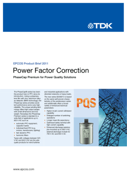
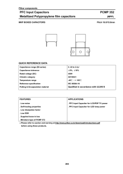
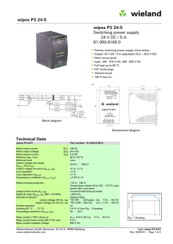
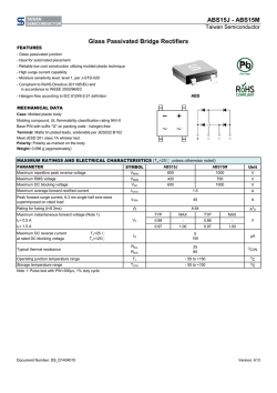
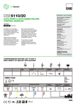
© Copyright 2026