
Canadian Pharmacy - BEST OFFERS | Levitra Allergia
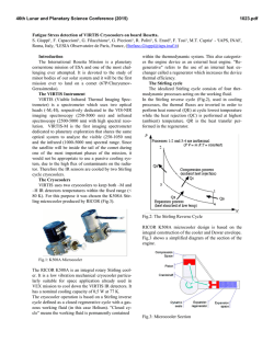
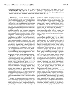
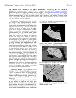
header for SPIE use
Extraction of VBIC Model for SiGe HBTs Made Easy
by Going through Gummel-Poon Model
Fujiang Lin*, Tianshu Zhou, Bo Chen, Ban Leong Ooi and Pang Shyan Kooi
*Singapore Microelectronics Modeling Center (SMMC), Agilent Technologies
438 Alexandra Road, Singapore 119958, Email: [email protected]
Electrical Engineering Department, National University of Singapore (NUS)
10 Kent Ridge Crescent, Singapore 119260
ABSTRACT
A new parameter extraction methodology - local ratio evaluation is presented which is well suited for converting one model
to another. An example is given for VBIC model extraction by going through Spice Gummel-Poon (SGP) model. It is based
on the fact that the VBIC model is a direct enhancement and extension of SGP model. Firstly, the standard SGP model is
extracted in the standard way. Then, SGP model parameters are directly converted to VBIC model. Next, local modifications
are carried out for those parameters that are affected by different equations used in the two models. Finally, new model
parameters for enhanced modeling features are introduced by evaluating the difference between measurement and simulation.
Keywords: parameter extraction, bipolar transistor modeling, compact models, SiGe HBT, VBIC, model conversion
1. INTRODUCTION
Bipolar junction transistors have been the workhorses in analog/RF applications for decades. Advances in modern processes
such as SiGe heterojunction transistors (HBTs) have shown the possible practical realization of low-cost communication
systems-on-chip (SOC). Due to its clear high-speed advantage and great design flexibility, SiGe HBT has emerged as the
technology of choice for new Comms-ICs (RF+Analog+Mixed-Signal).
The industry standard of bipolar transistor modeling is based on the Spice Gummel-Poon (SGP) model [1]. Though several
limitations exist for SGP model, until today no widely accepted alternative is available to replace it. Several advanced
models, such as VBIC [2], HICUM [3,4] and MEXTRAM [5] have been proposed and currently under evaluation by the
Compact Model Council of EIA in USA (http://www.eigroup.org/cmc/bipolar/default.htm). The VBIC model is the direct
extension of SGP model proposed by a group of people from widely representative industries, while the other two models are
developed independently and consistently by dedicated developers in conjunction with bipolar process development.
Two difficult situations are often faced for an IC designer: (a) model availability versus familiarity and (b) model complexity
versus simulation efficiency. It is therefore highly desirable that one model can be converted to another and two "consistent"
models can be provided for each technology: a simplified version for fast simulation and an enhanced version for detail and
critical prediction. In principle, the bipolar transistor modeling can fulfill these requirements.
Model parameter extraction is usually performed independently for each model based on separate standard electrical
characterization i.e. DC, CV and bias dependent S-parameters. This approach has few problems for simple models where
relatively less model parameters are needed such as SGP model. However, it may have problems for more advanced models
as follows: it consists of generally much more model parameters and often contains some conflicting parameters; an
advanced model are always less educated and stable. So, modeling engineers always feel frustrated if they go directly to the
advanced model extraction.
In this paper, we will present a new model extraction methodology: extracting an advanced model by going through a
simplified one. A simplified model provides an excellent starting point for an advanced model. In particular we present a new
methodology of extracting VBIC model by going through SGP model. Firstly, the standard SGP model is extracted in the
standard way. Then, SGP model parameters are directly converted to VBIC model. Next, local modifications are carried out
for those parameters that are affected by different equations used in the two models. Finally, new model parameters for
enhanced modeling features are introduced by evaluating the difference between measurement and simulation.
2. REVIEW OF VBIC MODEL
For the convenience of the readers, we summarize the VBIC model together with SGP model for comparison.
Fig. 1 The equivalent circuit of VBIC model
Fig. 2 The equivalent circuit of SGP model
VBIC Model
Four terminal model denoted by B, E, C and S
Self heating is modeled by sub-circuit
Excess-phase effect is modeled by a sub-circuit through
delay time TD which makes consistent small-signal to
transient analysis
Parasitic Capacitance CBE0 and CBC0 are included
Very complex substrate model
Main collector current source is symbolic identical
v
I cc =
v
ö
ö
ITF − ITR IS æç NFbei
IS æ bci
=
⋅ ç e ⋅VT − 1÷÷ − ⋅ çç e NR⋅VT − 1÷÷
qb
qb ç
÷ qb ç
÷
è
è
ø
ø
Early modeling is charge dependent (no simplification)
2
q1
q
+ æç 21 ö÷ + q 2
è ø
2
qje
qjc
q1 = 1 +
+
VER VEF
qb =
SGP Model
Three terminal model denoted by B, E, C
No self-heating
Forward excess-phase parameter PTF
Need to be added manually by macro model technique
No substrate model
Main collector current source
vbe
æ
è
Early modeling is simplified
q
qb ≈ 1 ⋅ 1 + 1 + 4 ⋅ q 2
2
v
v
1
q1 ≈ 1 + bc + be ≈
v
bc
VAF VAR 1 −
−
(
Vbci
æ
ø
è
vbc
ö
ø
)
VAF
Vbei
ö
÷ IS ç
÷
I − I R IS ç NF ⋅VT
I cc = F
=
⋅çe
− 1÷ − ⋅ ç e NR⋅VT − 1÷
qb
qb ç
÷ qb ç
÷
vbe
VAR
æ
ö
æ
ö
1
1
⋅ IS ⋅ ç e NF .VT − 1÷ +
⋅ IS ⋅ ç e NR⋅VT − 1÷
ç
÷ IKR
ç
÷
IKF
ø
æ
æ
ö
ö
1
1
q2 =
⋅ IS ⋅ çç e NF ⋅VT − 1÷÷ +
⋅ IS ⋅ çç e NR ⋅VT − 1÷÷
IKF
ç
ç
÷ IKR
÷
Forward base current is independent and distributed
Forward base current is coupled to collector current
q2 =
è
æ
ø
vbei
è
ö
æ
vbei
vbe
è
ö
I b, ges = IBEI ⋅ çç e NEI ⋅VT − 1÷÷ + IBEN ⋅ çç e NEN ⋅VT − 1÷÷
ç
è
÷
ø
I be = I bei + I ben = WBE ⋅ I b, ges
ç
è
I bex = I bexi + I bexn = (1 − WBE ) ⋅ I b, ges
vbc
÷
ø
æ
I be =
vbe
è
ø
ö
æ
ø
è
vbe
ø
ö
÷
ç
÷
IS ç NF ⋅VT
⋅çe
− 1÷ + ISE ⋅ ç e NE ⋅vT − 1÷
BF ç
÷
ç
÷
è
ø
Reverse base current is not coupled to emitter current
I bci + I bcn =
vbci
æ
IBCI ⋅ çç e NCI ⋅VT
ç
è
vbci
æ
ö
− 1÷÷ + IBCN ⋅ çç e NCN ⋅VT
ç
÷
è
ø
Reverse base current is coupled to emitter current
vbc
æ
ö
− 1÷÷
÷
ø
ö
æ
ø
è
vbc
ö
ç
÷
÷
IS ç NR⋅VT
I bc =
⋅çe
− 1÷ + ISC ⋅ ç e NC ⋅vT − 1÷
BR ç
ç
÷
÷
è
Weak avalanche current between base and collector
ø
No avalanche effect modeling
MC −1
I gc = (I cc − I bc ) ⋅ AVC1 ⋅ (PC − v bci ) ⋅ e − AVC 2⋅(PC − vbci )
Emitter resistor Re is constant
Emitter resistor Re is constant
Base resistor is modeled by conductivity modulation
Base resistor is modeled empirically
æ tan z − z ö
÷
Rb = RBM + 3 ⋅ (RB − RBM ) ⋅ çç
2 ÷
è z ⋅ tan z ø
R
Rb = Rbx + bi
qB
z=
Ib
( )2 ⋅ IRB
− 1 + 1 + 12
π
12
π2
Collector resistor consists of constant Rcx and variable Rc to
model quasi-saturation: Rc = Rcx + Rc (v bci , v bcx )
I Rc = I epi0
I epi0 =
æ
1 + ç I epi0
ç
è
⋅ R ci
æ
0.5⋅ 0.01+V 2
V 0 ⋅ ç1 + V 0⋅HRCFrci
ç
è
æ
1 + K bci
1 æç
⋅ v rci + VT ⋅ çç K bci − K bcx − ln
Rci çè
1
+ K bcx
è
öö
÷÷
÷÷
øø
⋅
Ib
IRB
Collector resistor Rc is constant
2
öö
÷÷
÷÷
øø
K bci = 1 + GAMM ⋅ e vbci / VT , K bcx = 1 + GAMM ⋅ e vbcx / VT
Substrate resistor Rs is constant
Space charge capacitance is same as SGP if AJi <0 is chosen
C Ji0
C Ji =
, forVbi < FC ⋅ Pi , i = E , C , S
æ1 − Vbi ö
ç
÷
Pi ø
è
Mi
NA
Space charge capacitance
C Ji 0
C Ji =
, forVbi < FC ⋅V Ji , i = E , C , S
æ1 − Vbi ö
ç
÷
VJi ø
è
linear continue afterwards
Can select single equation option
Diffusion capacitance enhanced by QTF
linear continue afterwards
Diffusion capacitance
Qbe = TFF ⋅ I F
Qbe = TFF⋅ I F
æ
ç
è
2
v
bci
ö
IF
÷ ⋅ e1.44⋅VTF
÷
è I F + ITF ø
æ
TFF = TF ⋅ (1 + QTF ⋅ q1 ) ⋅ çç1 + XTF ⋅ çç
M Ji
ö
÷
÷÷
ø
Qbc = TR ⋅ I R
Temperature mapping is much enhanced by 21 parameters
Enhanced Flicker noise model
é
ê
ë
2
vbc
ö
IF
÷ ⋅ e 1.44⋅VTF
÷
I
ITF
+
ø
è F
æ
TFF = TF ⋅ ê1 + XTF ⋅ çç
ù
ú
ú
û
Qbc = TR ⋅ I R
Temperature modeling is very simple, 4 parameters
Flicker Noise model
From the comparison above, we can summarize the following major improvement of VBIC model over SGP model:
§
§
§
§
§
Correct early effect model based on the junction charges without making simplification
Modified Kull model for quasi-saturation valid into high-injection at the collector
Parasitic substrate transistor
Weak avalanche current is included for base-collector junction
Self-heating model is defined as hooked in code by sub-circuit
§
§
§
§
§
§
§
First-order model of distributed-base for AC and DC emitter crowding
Improved single-piecewise junction capacitance model is added as option
Improved complete static temperature mapping
Inclusion of overlap capacitance
Improved high-level diffusion capacitance modeling
Second-order excess phase network consistent with AC->transient
High-order continuity in equations
3. CONVERTING SGP MODEL TO VBIC MODEL
From the above comparison, we can see that VBIC model is fully based on the SGP model with enhancement in two ways: to
improve it by better equations and to add on additional feature. Based on this analysis, we believe that there must exist a
“shortcut” for the VBIC parameters extracting “directly” from all the available SGP model parameters instead of doing it
from scratch [6]. We have experienced very well in practice with this new approach. It is summarized in the following table.
VBIC
SGP
Typical Converting
Main Collector Current Source
IS
IS
IS*0.9
NF
NF
NR
NR
Early Modeling
VEF
VAF
VAF*0.5
VER
VAR
VAR*0.5
Webster Effect
IKF
IKF
IKF*0.9
IKR
IKR
IKR*0.9
Forward Base Current
IBEI
IS/BF
NEI
NF
IBEN
ISE
NEN
NE
WBE
1.0
Reverse Base Current
IBCI
IS/BR
NCI
NR
IBCN
ISC
NCN
NC
Weak Avalanche Current
AVC1
0.15
AVC2
20
Parasitic Resistance
RE
RE
RBX
RBM
RBI
RB
IRB
RS
RBP
RCX
RC
Quasi-Saturation
RCI
RC*10
GAMM
100p
VO
1.5
Remarks
Transport saturation current, IS in VBIC is smaller due to different qb modeling
Forward current emission coeff.
Reverse current emission coeff.
Early effect is modeled differently in two models, in general VBIC early voltage
is smaller than SGP
High-current roll-off is less effective in VBIC model
VBIC model the ideal B-E diode independently
Non-ideal B-E leakage diode
Distributed base parameter, no distributed base modeling by set to one
VBIC model the ideal B-C diode independently
Non-ideal B-C leakage diode
The bias-dependent base resistance is modeled differently in both models
Constant external collector resistor
VBIC has a modified Kull model implemented
HRCF
33m
QCO
1.0f
Space Charge Capacitance
CJE
CJE
PE
VJE
ME
MJE
AJE
-0.5
Space charge model selector (-0.5 select SGP model)
CJC
CJC
PC
VJC
MC
MJC
AJC
-0.5
Space charge model selector (-0.5 select SGP model)
CJEP
XCJC
(1-XCJC)*CJC
CJCP
CJS
PS
VJS
MS
MJS
AJS
-0.5
Space charge model selector (-0.5 select SGP model)
FC
FC
0.9
Transit Time (Diffusion Capacitance) Modeling
TF
TF
TF*0.25
VBIC model reduced in TF due to additional QTF parameter
XTF
XTF
ITF
ITF
VTF
VTF
QTF
0.3
Describes the additional dependency to q1
TR
TR
Excess Phase
TD
PTF
VBIC is implemented by sub-circuit which is consistent in ac=>transient analysis
TF*PTF*180/π
Parasitic Capacitance
External overlap capacitance need to be added manually in SGP model
CBE0
CBC0
Parasitic Substrate Transistor
ISP
SGP does not cover substrate transistor
NFP
WSP
Distributed factor to vbci and vbep
IBEIP
NEIP=NCI
IBENP
NENP=NCN
IBCIP
NCIP
IBCNP
NCNP
IKP
Temperature Mapping
CTH
100p
VBIC includes a self-heating sub-circuit
RTH
200
TAMP
TNOM
TNOM TNOM
EA
EG
EAIE
EAIC
EAIS
EANE
EANC
EANS
XRE
-
XRB
XRC
XRS
XVO
XIS
XTI
XII
XTB
XIN
XTB
XNF
TAVC
Noise Modeling
KFN
KF
AFN
AF
BFN
-
1
VBIC model enhanced the flicker noise in 1/f ^BFN dependence
In the above Table, the column VBIC lists all the VBIC model parameters. In the column SGP is the correlated SGP model
parameters if there is any. In the column Typical Converting is the modification needed for converting SGP to VBIC. In
general it is a SGP model parameter modified by a factor. This is the desired converting formula we aimed to find out in this
project. At this moment, it is still not completed as our study is continuing. If the advanced VBIC model parameters are not
assigned (noted by sign "-" in SGP column), their default values are used where their effects are disabled [6]. We can see that
most SGP model parameters are directly converted to VBIC and some need necessary modification.
(1) Main collector current source: We keep forward and reverse current emission coefficients NF and NR no change in
both models. However, due to different base charge modulation model in qb, transport saturation current IS in VBIC has
to be modified, usually is smaller than in SGP. Exact correcting factor can be easily calculated by comparing the
difference between simulation and measurement. We call this extraction technique as "local ratio evaluation". Detail of it
will be given in the next section.
(2) Early voltage: The implementation of the Early effect in the SGP and the VBIC model is so different that strictly
speaking, the parameters cannot be converted directly. Yet, we find out that in general the SGP Early parameters are
bigger than those of the VBIC. So we recommend that the early voltage should be converted with half reduction and
modified by local ration evaluation as will be given in the next section.
(3) Charge capacitance: The space charge capacitance is the same if selector Aji (i=E,C,S) is set to a negative value. All
space charge capacitance parameters are converted directly.
(4) Diode currents: In VBIC, the ideal base current is not coupled to the transport currents, so, there is IBEI=IS/BF and
IBCI=IS/BR. The SGP model parameters of the non-ideal or recombination section of the base current can, however, be
transferred directly to those corresponding parameters of VBIC model.
(5) Parasitic transistor: We expected to make use of main NPN transistor to obtain first order parasitic PNP transistor
parameters.
(6) Transit time parameters: If we set QTF=0, then the GP parameters of the transit time TFF as well as the excess phase
can be transferred to VBIC model parameters without any change. If QTF is introduced, TF will be reduced.
(7) Quasi-saturation: The SiGe HBT has quasi-saturation (QS) resulting in bias-dependent current gain drop (in contrast,
GaAs-based HBT is dominated by base push-out resulting in bias-dependent variation of Cbc, no current gain drop. It is
not covered in VBIC model). Typical values for SiGe HBT are assigned which can be modified in later local ratio
evaluation.
4.
LOCAL RATIO EVALUATION TECHNIQUE
This new parameter extraction technique is very useful if the current model parameter value is not too far away from its final
one. Its typical application situations are, for example:
(a) determine a model parameter which is converted from other model (such as VBIC from SGP) by error correction;
(b) update an existing model for new wafer lot run which may have some shift in technologies with time;
(c) extract a model for similar wafers or chips for typical and worst models or statistical derivation;
(d) model extraction for same DUT under different temperature, etc.
The key point is to avoid complex mathematical solution in order to find out exact extraction equation and to avoid using an
optimizer or manual tuning procedure. To demonstrate it and make it easier to understand, we take a real example of
extracting the Early voltage VEF and transport saturation current IS in VBIC when it is converted from SGP model (VAF
and IS). This is taken from a real SiGe HBT modeling data.
Fig. 3a is the measured and simulated current-voltage characteristic of a SiGe HBT device. The solid line is measured and
doted line is simulated by VBIC model whose parameters are converted directly from SGP model extraction. Now the
simulation is shifted from measurement. This is because the Early modeling is different in both models. From this plot we
can correct the converted parameter values for VEF and IS in a simple way as follows:
Correct VEF: We know that VEF will determine the slop of the I-V curve in saturation. Select any two points in the
I sim − I c1 sim
VEF new = VEF ⋅ c2
I c 2 mea − I c1 mea
After this correction the new simulation is as shown in Fig. 3b. The slopes for simulation and measurement are now the same.
Correct IS: Next we correct IS which determines the high of simulated current curve. Select any one point in the saturation
region and the correction factor is:
I mea
IS new = IS ⋅ c
I c sim
After this correction, the final simulation fit the measurement as shown in Fig. 3c.
Fig. 3
I-V characteristic of a SiGe HBT (Solid line: measurement, doted line: simulation by VBIC)
(a) Simulation by parameters directly converted from SGP
(b) Simulation after VEF correction by local ration technique
(c) Simulation after IS correction
5.
THE EXPERIMENT, RESULT AND DISCUSSION
The extraction is implemented in Agilent IC-CAP with two circuits and two simulators realized in a single model set-up.
Basic procedure is as follows:
§
§
§
§
§
Firstly, SGP model is extracted with Spice simulator and well-established extracting routines [6].
Then, SGP model parameters are directly converted to VBIC model circuit page with all other VBIC advancing features
turned off. In this case, VBIC is equivalent to SGP except the different formula used for integrated charge control
relation qb.
Next, by evaluating the difference between measurement and simulation, the difference of Qb modeling is corrected by
local ration evaluation technique.
Finally, new features of quasi-saturation, self-heating and weak avalanche etc are introduced in sequence.
Above steps can be sped up by using typical converting formula listed in column 3 of Table 2.
The experimental results are presented in Figures 4-8.
Fig. 4 shows typical plots of SiGe HBT characteristics modeled with SGP that has no quasi-saturation (QS), self-heating
(ST), weak avalanche (AV) modeling. Fig. 4a is the standard output I-V characteristic that clearly shows the differences in
QS and AV regions. Fig. 4b is the external base-emitter voltage versus collector-emitter voltage with base current as a
parameter. The negative slope shows the voltage drop in the channel due to the self-heating effect. Fig. 4c is the conventional
plot of cut-off frequency versus collector current with base current as a parameter. It can be seen that the base current
dependency is not well modeled for SiGe HBT devices.
Fig. 5 shows the same plots as Fig. 4. Now the simulation is carried out using VBIC model whose parameters are converted
directly from SGP model extraction. All advanced features in VBIC are disabled. It should produce the same result as SGP
model. The difference in simulation is due to the different Early modeling used in both models.
Fig. 6 shows the same plots as Fig. 5, now VBIC model parameters are converted from SGP with typical modification as
given in column 3 of Table 2. It shows clearly the improvement in QS, but not as good in ST.
Fig. 7 shows the changes when ST is corrected. However, due to self-heating effect, other model parameters need to be
modified in stressing the high-power region.
Fig. 8 is the final result after all these corrections. QS, ST are well modeled. However, the weak avalanche effect cannot be
modeled correctly in both high and low current regions simultaneously. We discover that it is due to the limitation of weak
AV model in VBIC. Another paper address this issue [7] will be published.
6. CONCLUSION
We have compared the VBIC and SGP model in an easy reference table. We have presented a novel approach to obtain the
VBIC model parameters based on the SGP model parameters. The practical benefits of this work are:
§
§
§
Two models are extracted where SGP can be used as simplified version and VBIC as advanced one.
Less frustration in advanced model extraction by going through simple one. It can be made possible for engineer to
extract VBIC model even without much knowledge of it.
It may be possible to generate a VBIC model from an existing SGP model by simple converting formulas. This is
currently under further development.
7. REFERENCES
1.
2.
3.
4.
5.
6.
7.
H.K. Gummel and H.C. Poon, "An integrated charge control model of bipolar transistors," Bell Syst. Tech. J. Vol. 49,
May 1970, pp.827-850.
C. McAndrew, et al, "VBIC95: An improved vertical, IC bipolar transistor model," in Proceedings of the 1995 BiCMOS
Circuits and Technology Meeting, 1995, Minneapolis, pp.170-177.
H. Stubing and H. M. Rein, "A compact physical large-signal model for high-speed bipolar transistors at high current
densities-part I: one-dimensional model," IEEE Trans. Electron Devices, vol. 34, August 1987, pp. 1741-1751.
H. M. Rein and M. Schroter, "A compact physical large-signal model for high-speed bipolar transistors at high current
densities- part II: two-dimensional model and experimental results," IEEE Trans. Electron Devices, vol. 34, August
1987, pp. 1752-1761.
H. C. De Graaff and W. J. Kloosterman, "New formulation of the current and charge relations in bipolar transistor
modeling for CACD purposes," IEEE Trans. Electron Devices, vol. 32, November 1985, pp. 2415-2419.
Franz Sischka, The IC-CAP Modeling Reference Book, Agilent EEsof, 1998.
F. Lin, B. Chen, T. Zhou, B.L. Ooi and P.S. Kooi, "Characterization and Modeling of Avalanche Multiplication in
HBTs," in this proceeding.
QS
ST
AV
Fig. 4: I-V characteristic and simulation with SGP for an SiGe HBT device showing no quasi-saturation (QS), weak
avalanche (AV), self-heating effect (ST), and poor transit time modeling.
Fig. 5: Same characteristic as Fig. 4 but simulation with VBIC. Model parameters are converted directly from SGP, i.e. all
advanced features in VBIC are disabled. The difference in QS and fT are due to the different Early modeling in two models.
Fig. 6: Same characteristic as Fig. 5 but VBIC model parameters are converted from SGP with additional extension: reduced
IS, VEF, IKF, and TF, enlarged RCI and RBI.
Fig. 7: Same characteristic as Fig. 6. Now self-heating sub-circuit is included and local corrected. However, parameters IS,
TF, VEF are affected due to the self-heating mode.
Fig. 8: Final IV characteristic and simulation with VBIC showing QS, AV and ST effect are included. VBIC model well in
QS and ST. However, AV and the transit time modeling are still poor. It can not model well in both high and low current
regions.

© Copyright 2026