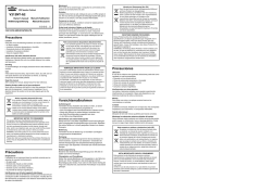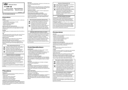
mini 5 REV02 170604.qxp
Pag. 1 di 4
ISTRUZIONI DI MONTAGGIO - INSTRUCTION POUR LE MONTAGE
ASSEMBLY INSTRUCTIONS - MONTAGEANWEISUNGEN
INSTRUCCIONES DE MONTAJE
Mod.
MINI 5
Quadro elettrico per il comando di 5 motori singolarmente e/o simultaneamente, in modo manuale, per l'automazione di tapparelle e tende da sole.
Coffret électrique pour la commande de 5 moteurs individuellement ou simultanément, en manuel, pour l'automatisation de volets et stores.
Electric panel for the single and/or simultaneous control of 5 motors, manual mode, for the automation of roller shutters and sun-blinds.
Elektrische Steuerung für die Steuerung von 5 Motoren - einzeln, und/oder gleichzeitig, manuell - für die Automation von Rolläden und Sonnendächern.
Cuadro eléctrico para el mando de 5 motores singularmente y /o juntamente, de forma manual, para la automatización de cortinas normales y para sol
COMANDO MANUALE PER OGNI SINGOLO MOTORE
La centrale dispone di 5 ingressi (INPUT 1-2-3-4-5) per il collegamento di 5
pulsantiere APRE/CHIUDE. Ad ogni ingresso è associato il rispettivo motore
(MOTORE 1-2-3-4-5). Mantenendo costantemente attivato il comando di apertura o chiusura, si
otterrà l'azionamento del rispettivo motore.
COMMANDE MANUELLE POUR CHAQUE MOTEUR INDIVIDUELLEMENT
La centrale dispose de 5 entrées (INPUT 1-2-3-4-5) pour la connexion de 5
tableaux de commandes OUVERTURE/FERMETURE. Chaque entrée a son
respectif moteur (MOTEUR 1-2-3-4-5), en maintenant la commande d'ouverture ou de fermeture
constamment actionnée, vous obtiendrez le fonctionnement du moteur respectif.
COMANDO MANUALE CENTRALIZZATO
La centrale dispone di un ingresso (GEN. SLAVE) per il collegamento di una pulsantiera
APRE/CHIUDE. Mantenendo costantemente attivato il comando di apertura o chiusura si otterrà
l'azionamento di tutte le 5 uscite motore per il senso di marcia selezionato.
COMMANDE MANUELLE CENTRALISEE
La centrale dispose d'une entrée (GEN. SLAVE) pour la connexion d'un tableau de commandes
OUVERTURE/FERMETURE. En maintenant la commande d'ouverture ou de fermeture
constamment activée, vous obtiendrez le fonctionnement de toutes les 5 sorties moteur dans le
sens de la marche sélectionné.
I
RAGGRUPPAMENTO DI DUE O PIU’ CENTRALI PER IL COMANDO SIMULTANEO:
Raggruppamento per il comando manuale centralizzato.
Ogni centrale dispone di un ingresso (GEN. SLAVE) per il comando simultaneo dei 5 motori in
modo manuale, connettendo in parallelo agli stessi ingressi un’altra identica centrale e poi
collegandovi una pulsantiera APRE/CHIUDE otterremo il seguente funzionamento: mantenendo
costantemente attivato il comando di apertura o chiusura, si otterrà l'azionamento di tutte le uscite
motore per il senso di marcia selezionato.
MANUAL CONTROL FOR EACH SINGLE MOTOR.
The central has got 5 input (INPUT 1-2-3-4-5) for the connection of 5
OPEN/CLOSE push button panels. Each input has got its motor (MOTOR 1-2-34-5), by activating the OPEN or CLOSE control constantly, the relative motor will start running.
GB
CENTRALISED MANUAL CONTROL
The central has got an input (GEN. SLAVE) for the connection to an OPEN/CLOSE push-button
panel. By activating the OPEN or CLOSE control constantly all the five motors will start running.
GROUPING TWO OR MORE CENTRALS FOR SIMULTANEOUS CONTROL:
Grouping for the centralised manual control.
Each central has got an input (GEN. SLAVE) for the simultaneous control of the 5 motors in
manual mode, connect another similar central parallel to the same inputs, then connect a pushbutton panel (OPEN/CLOSE) to obtain the following functioning:
by activating the OPEN or CLOSE control constantly, all the motor outputs will start running in the
chosen direction.
MANDO MANUAL PARA CADA MOTOR
La central dispone de 5 entradas (INPUT 1-2-3-4-5) para la conexión de 5 cajas
de pulsadores ABRE/CIERRA, a cada entrada se asocia el respectivo motor
(MOTOR 1-2-3-4-5), manteniendo constantemente activado el mando de abertura y cierre, se
accionará el respectivo motor.
E
MANDO MANUAL CENTRALIZADO
La central dispone de una entrada (GEN. SLAVE) para la conexión de una cajas de pulsadores
ABRE/CIERRA manteniendo constantemente activado el mando de abertura o cierre, se
accionarán todas las salidas motor según el sentido de marcha seleccionado.
AGRUPAMIENTO DE DOS O MAS CENTRALES PARA EL MANDO SIMULTANEO:
Agrupamiento para el mando manual centralizado.
Cada central dispone de una entrada (GEN. SLAVE) para el mando simultáneo de los 5 motores
de manera manual, conexionando en paralelo a estas entradas otra idéntica central y después
conectando una caja de pulsadores ABRE/CIERRA, se obtendrá el siguiente funcionamiento:
manteniendo constantemente activado el mando de abertura o cierre, se accionará, todas las
salidas motor según el sentido de marcha seleccionado.
F
GROUPEMENT DE DEUX OU PLUSIEURS CENTRALES
POUR LA COMMANDE SIMULTANÉE:
Groupement pour la commande manuelle centralisée.
Chaque centrale dispose d'une entrée (GEN. SLAVE) pour la commande simultanée de 5
moteurs, en mode manuel; si vous connectez en parallèle aux mêmes entrées une autre centrale
identique et qu'ensuite vous connectez un tableau de commandes OUVERTURE/FERMETURE,
vous obtiendrez le fonctionnement suivant:
en maintenant la commande d'ouverture et de fermeture constamment activée vous obtiendrez le
fonctionnement de toutes les sorties moteur dans le sens de la marche sélectionné.
HANDSTEUERUNG FÜR JEDEN EINZELNEN MOTOR
Die Zentrale verfügt über 5 Eingänge (INPUT 1-2-3-4-5) für den Anschluß von 5
Druckknopftafeln ÖFFNEN/SCHLIEßEN. Jedem Eingang ist der entsprechende
Motor zugeteilt ( MOTOR 1-2-3-4-5 ). Wenn die Steuerung der Öffnung oder Schließung ständig
tätig bleibt, löst sie den Antrieb des entsprechenden Motors aus.
D
ZENTRALISIERTE HANDSTEUERUNG
Die Zentrale verfügt über einen Eingang (GEN. SLAVE) für den Anschluß einer Druckknopftafel
ÖFFNEN/SCHLIEßEN. Wenn die Steuerung der Öffnung oder Schließung ständig tätig bleibt, löst
sie die Betätigung aller 5 Motorenausgänge für die gewählte Laufrichtung aus.
GRUPPIERUNG VON ZWEI ODER MEHREREN ZENTRALEN FÜR DIE
SIMULTANSTEUERUNG.
Gruppierung zentralisierte Handsteuerung.
Jede Zentrale verfügt über einen Eingang (GEN. SLAVE) für die manuelle Simultansteuerung von
5 Motoren. Verbindet man parallel zu diesen Eingängen eine andere identische Zentrale und
schließt dann eine Drucknopftafel daran an, erzielt man folgenden Arbeitsgang: wenn die
Steuerung der Öffnung oder Schließung ständig tätig bleibt, löst sie die Betätigung aller
Motorenausgänge für die gewählte Laufrichtung aus.
Pag. 2 di 4
I
ISTRUZIONI IMPORTANTI DI SICUREZZA PER L’INSTALLAZIONE
ATTENZIONE L’INSTALLAZIONE NON CORRETTA PUO’ CAUSARE GRAVI
DANNI
SEGUIRE TUTTE LE ISTRUZIONI DI INSTALLAZIONE
F
IMPORTANTES INSTRUCTIONS DE SECURITE POUR L’INSTALLATION
ATTENTION UNE INSTALLATION NON CORRECTE PEUT CAUSER DE
GRAVES DOMMAGES
SUIVRE TOUTES LES INSTRUCTIONS D’INSTALLATION
1° - Questo libretto d'istruzioni è rivolto esclusivamente a del personale specializzato che sia a
conoscenza dei criteri costruttivi e dei dispositivi di protezione contro gli infortuni per i cancelli, le porte e i
portoni motorizzati (attenersi alle norme e alle leggi vigenti).
2° - L’installatore dovrà rilasciare all’utente finale un libretto di istruzioni in accordo alla EN 12635.
3° - L’installatore dovrà applicare in prossimità dei comandi o del cancello delle etichette di attenzione sui
pericoli da intrappolamento.
4° - Controllare spesso l’impianto, in particolare i cavi, le molle e i supporti per scoprire eventuali sbilanciamenti
e segni di usura o danni. L’utente finale non deve azionare elettricamente il cancello se questo necessita
di manutenzione o riparazione dal momento che un guasto all’installazione o una porta non correttamente
bilanciata può provocare ferite.
5° - L’installatore prima di procedere con l’installazione deve prevedere l’analisi dei rischi della chiusura
automatizzata finale e la messa in sicurezza dei punti pericolosi identificati (seguendo la norma EN
12453/EN 12445).
6° - L’installatore prima di procedere con l’installazione deve togliere funi o catene superflue e disabilitare
qualsiasi apparecchiatura non necessaria dopo l’instaallazione del motore di movimentazione.
7° - L’installatore prima di installare il motore di movimentazione deve verificare che la porta sia in buone
condizioni meccaniche e che si apra e chiuda adeguatamente.
8° - L’installatore dovrà rimuovere eventuali impedimenti al movimento motorizzato del cancello (es.
chiavistelli, catenacci, serrature ecc.)
9° - Il cablaggio dei vari componenti elettrici esterni all’operatore (ad esempio fotocellule, lampeggianti, ecc.)
deve essere effettuato secondo la EN 60204-1 e le modifiche a questa apportate dal punto 5.2.2 della EN
12453.
10° - L’eventuale montaggio di una pulsantiera per il comando manuale del movimento deve essere fatto
posizionando la pulsantiera in modo che chi la aziona non si trovi in posizione pericolosa; inoltre si dovrà
fare in modo che sia ridotto il rischio di azionamento accidentale dei pulsanti.
11° - Tenete i comandi dell'automatismo (pulsantiera, telecomando etc.) fuori dalla portata dei bambini. I
comandi devono essere posti ad un’altezza minima di 1,5mt dal suolo e fuori dal raggio d’azione delle parti
mobili.
12° - Prima di eseguire qualsiasi operazione di installazione, regolazione, manutenzione dell’impianto, togliere
la tensione agendo sull’apposito interruttore magnetotermico collegato a monte dello stesso.
LA DITTA RIB NON ACCETTA NESSUNA RESPONSABILITÀ per eventuali danni provocati dalla mancata
osservanza nell'installazione delle norme di sicurezza e delle leggi attualmente in vigore.
1° - Ce livret d’instructions est adressé exclusivement à un personnel spécialisé qui connaît les critères
de construction et les dispositifs de protection contre les accidents concernant les portails, les portes et les
portes cochères motorisés (s’en tenir aux normes et aux lois en vigueur).
2° - L’installateur devra délivrer à l’utilisateur final un livret d’instruction en accord à la EN 12635.
3° - L’installateur devra appliquer à proximité des commandes ou des portails, des étiquettes de mise en garde
contre le danger d’être pris dans la fermeture.
4° - Souvent contrôler l’installation, en particulier les câbles, les ressorts et les supports pour découvrir
d’éventuels deséquilibrages et signes d’usure ou dommages. L’utilisateur final ne doit pas actionner
électriquement le portail si celle-ci a besoin d’entretien ou de réparation, à partir du moment où une panne
à l’installation ou une porte mal équilibrée peut être cause de blessures.
5° - L’installateur avant de procéder à l’installation, doit prévoir l’analyse des risques de la fermeture
automatisée finale et la mise en sécurité des points identifiés dangereux (en suivant la norme EN
12453/EN 12445).
6° - L’installateur avant de procéder à l’installation, doit retirer les cordes ou chaînes superflues et déshabiliter tout
appareillage qui n’est pas nécessaire après l’installation du moteur de mouvement.
7° - L’installateur, avant d’installer le moteur de mouvement, doit vérifier que le portail soit en bonnes conditions
mécaniques et qu’elle s’ouvre et se ferme correctement.
8° - L’installateur devra retirer d’éventuels obstacles au mouvement motorisé du portail (ex. verrous, serrures, etc).
9° - Le câblage des divers composants électriques externes à l’opérateur (par exemple photocellules,
clignotants, etc) doit être effectué selon la EN 60204-1 et les modifications apportées à celle-ci dans le
point 5.2.2 de la EN 12453.
10° - Le montage éventuel d’un tableau pour la commande manuelle du mouvement doit être fait en positionnant
le tableau de façon à ce que la personne qui l’actionne ne se trouve pas en position de danger ; de plus,
il faudra faire en sorte que le risque d’actionnement accidentel des boutons soit réduit.
11° - Tenir les commandes de l’automatisme (tableau, télécommande, etc) hors de portée des enfants. Les
commandes doivent être placées à une hauteur minimum de 1,5 m du sol et hors du rayon d’action des
parties mobiles.
12° - Avant l’exécution de toute opération d’installation, de réglage, d’entretien de l’installation, couper le courant
en agissant sur l’interrupteur magnétothermique à cet effet, branché en amont de l’installation.
LA SOCIETE RIB N’ACCEPTE AUCUNE RESPONSABILITE pour d’éventuels dommages provoqués par la
non-observation dans l’installation, des normes de sécurité et des lois actuellement en vigueur.
IMPORTANTI ISTRUZIONI PER LA SICUREZZA
ATTENZIONE PER LA SICUREZZA DELLE PERSONE É IMPORTANTE CHE VENGANO
SEGUITE TUTTE LE ISTRUZIONI
CONSERVARE CON CURA QUESTE ISTRUZIONI
INSTRUCTIONS IMPORTANTES POUR LA SECURITE
ATTENTION POUR LA SECURITE DES PERSONNES IL EST IMPORTANT
DE SUIVRE TOUTES LES INSTRUCTIONS
CONSERVER SOIGNEUSEMENT CES INSTRUCTIONS
1° - Se non é previsto nella centralina elettrica, installare a monte della medesima un'interruttore di tipo
magnetotermico (onnipolare con apertura minima dei contatti pari a 3mm) che riporti un marchio di
conformità alle normative internazionali. Tale dispositivo deve essere protetto contro la richiusura
accidentale (ad esempio installandolo entro quadro chiuso a chiave).
2° - Per la sezione ed il tipo dei cavi la RIB consiglia di utilizzare un cavo di tipo NPI07VVF con sezione minima
di 1,5mm2 e comunque di attenersi alla norma IEC 364 e alle norme di installazione vigenti nel proprio
Paese.
3° - Posizionamento di un’eventuale coppia di fotocellule: Il raggio delle fotocellule deve essere ad un’altezza
non superiore a 70 cm dal suolo e ad una distanza dal piano di movimento della porta non superiore a 20
cm. Il loro corretto funzionamento deve essere verificato a fine installazione in accordo al punto 7.2.1 della
EN 12445.
4° - Per il soddisfacimento dei limiti imposti dalla EN 12453, se la forza di picco supera il limite normativo di 400
N è necessario ricorrere alla rilevazione di presenza attiva sull’intera altezza della porta (fino a 2,5m max) Le fotocellule in questo caso sono da applicare come indicato nella norma EN 12445 punto 7.3.2.2).
N.B.:É obbligatoria la messa a terra dell'impianto
I dati descritti nel presente manuale sono puramente indicativi.
La RIB si riserva di modificarli in qualsiasi momento.
Realizzare l’impianto in ottemperanza alle norme ed alle leggi vigenti.
1° - Si ce n’est pas prévu dans la centrale électrique, installer en amont de celle-ci un interrupteur de type
magnétothermique (omnipolaire avec ouverture minimum des contacts de 3 mm) qui porte une marque de
conformité aux normes internationales. Ce dispositif doit être protégé contre la re-fermeture accidentelle
(par exemple en l’installant dans un tableau fermé à clé).
2° - En ce qui concerne la section et le type des câbles, la RIB conseille d’utiliser un câble de type NPI07VVF
ayant une section minumum de 1,5mm2 et de toute façon, s’en tenir à la norme IEC 364 et aux normes
d’installation en vigueur dans le propre pays.
3° - Positionnement d’un couple éventuel de photocellules : Le rayon des photocellules doit se situer à une
hauteur qui ne doit pas être supérieure à 70 cm du sol et à une distance du plan de mouvement de la porte
qui ne doit pas être supérieure à 20 cm. Leur bon fonctionnement doit être vérifié en fin d’installation selon
le point 7.2.1 de la EN 12445.
4° - Pour satisfaire aux limites imposées par la EN 12453, si la force de pointe dépasse la limite de la norme de
400 N, il est nécessaire de recourir au relevé de présence active sur la hauteur totale de la porte (jusqu’à
2,5m max). - Les photocellules, dans ce cas, doivent être appliquées selon le point 7.3.2.2 de la EN 12445.
N.B.: La prise de terre est obligatoire sur l’installation.
Les données décrites dans ce manuel sont purement indicatives.
La RIB se réserve le droit de les modifier à tout moment.
Réaliser l’installation en conformité aux normes et aux lois en vigueur.
Pag. 3 di 4
GB
IMPORTANT SAFETY INSTRUCTIONS FOR THE INSTALLATION
ATTENTION THE INCORRECT INSTALLATION CAN CAUSE SERIOUS
DAMAGES
FOLLOW ALL INSTALLATION INSTRUCTIONS
D
WICHTIGE SICHERHEITS ANLEITUNGEN FÜR DIE INSTALLATION
ACHTUNG EINE UNKORREKTE INSTALLATION KANN SCHWERE
SCHÄDEN VERURSACHEN.
ALLE INSTALLATIONSANLEITUNGEN BEFOLGEN
1° - This handbook is exclusively addressed to the specialized personnel who knows the constructive
criteria and the protection devices against the accidents for motorized gates, doors and main doors (follow
the standards and the laws in force).
2° - The installer will have to issue a handbook to the final user in accordance with the EN 12635.
3° - The installer will have to put the tags warning against the entrapping dangers near the controls and the
gates.
4° - Check frequently the system, in particular cables, springs and supports to find out possible unbalances,
wear signs or damages. The final user must not operate electrically the gate if this needs maintenance or
repair, since a failure in the installation or a non correctly balanced barrier can provoke wounds.
5° - Before proceeding with the installation, the installer must forecast the risks analysis of the final automatized
closing and the and the safety of the identified dangerous points (Following the standards EN 12453/EN
12445).
6° - Before proceeding with the installation, the installer must remove superfluous cables or chains and disable
any unnecessary device after the installation of the motion motor.
7° - Before installing the motion motor, the installer must verify that the door is in good mechanical conditions
and that it adequately opens and closes.
8° - The installer will have to remove possible impediments to the motorized motion of the gate (eg. Door bolts,
sliding bolts, door locks etc.)
9° - The wiring harness of the different electric components external to the operator (for example photoelectric
cells, flashlights etc.) must be carried out according to the EN 60204-1 and the modifications to it done in
the point 5.2.2 of the EN 12453.
10° - The possible assembly of a keyboard for the manual control of the movement must be done by positioning
the keyboard so that the person operating it does not find himself in a dangerous position; moreover, the
risk of accidental activation of the buttons must be reduced.
11° - Keep the automatism controls (push-button panel, remote control etc.) out of the children way. The controls
must be placed at a minimum height of 1,5mt from the ground and outside the range of the mobile parts.
12° - Before carrying out any installation, regulation or maintenance operation of the system, take off the voltage
by operating on the special magnetothermic switch connected upstream.
THE RIB COMPANY DOES NOT ACCEPT ANY RESPONSIBILITY for possible damages caused by the non
observance during the installation of the safety standards and of the laws in force at present.
1° - Diese Betriebsanleitung dient ausschließlich dem Fachpersonal, welches die Konstruktionskriterien
und die Sicherheits-Vorschriften gegen Unfälle für Tore, Türen und automatische Tore Kennt (geltende
Normen und Gesetze beachten und befolgen).
2° - Der Monteur muss dem Endkunde eine Betriebsanleitung in Übereinkunft der 12635 überreichen.
3° - Der Monteur muss in Nähe der Steuerung oder des Tore Etiketten anbringen, die auf die
Einklemmgefahren hinweisen.
4° - Die Anlage oft kontrollieren, besonders Kabel, Federung und Halterung, um eventuelle
Gleichgewichtsstörungen und Abnützungszeichen oder Schäden zu entdecken. Der Endkunde darf das
Tor nicht elektrische betätigen, wenn dieses Unterhalt oder Reparaturen benötigt, oder weil dieses nicht
korrekt installiert, oder ein Tor nicht richtig ausbalanciert wurde, und deswegen zu Verletzungen führen
kann.
5° - Vor der Installierung muss für die automatische Schließung und zur Sicherheitsgewährung der
identifizierten kritischen Punkte, eine Risiko Analyse vorgenommen werden (die Normen EN 12453/EN
12445 befolgend).
6° - Der Fachmann muss vor Installierung alle unnötigen Hindernisse beseitigen, wie Seile, Taue oder Ketten und
nach Installierung des Bewegungsmotors alle nicht nötigen Geräte ausschalten.
7° - Vor Installierung des Bewegungsmotors, muss der verantwortliche Fachmann sich vergewissern, dass sich
das Tor in guter mechanischer Kondition befindet, und, dass es sich angebracht öffnet und schließt.
8° - Der Installateur hat alles was die automatische Bewegung des Tores behindert wegzuräumen, wie z.B.
Riegel, Schieber, Ketten Schlüssel-Schlösser usw.
9° - Die Verkabelung der verschiedenen externen elektrischen Komponenten zum Operator (z.B. Fotozellen,
Blinker etc.) muss nach EN 60204-1 ausgeführt werden, Änderungen davon nach Punkt 5.2.2 der EN
12453.
10° - Die eventuelle Montage einer Schalttafel für den manuellen Bewegungsbefehl muss so angebracht
werden, dass der Benutzer sich nicht in Gefahrenzone befindet, und dass das Risiko einer zufälligen nicht
gewollten Aktivierung von Schaltern gering ist.
11° - Befehlkommandos für die Automatisierung (Schalttafel, Fernbedienung usw.) gehören nicht in Reichweite
von Kindern. Die Kommandos müssen min. 1,5 m. ab Boden und außerhalb des Aktionsbereiches der
mobilen Teile angebracht werden.
12° - Vor jeglichem Eingriff, sei es Installation, Regulierung oder Wartung der Anlage, muss vorher die
Stromzufuhr unterbrochen werden, den dafür bestimmten Magnetthermo-Schalter drücken, der oben an
der Anlage installiert ist.
DIE FIRMA RIB ÜBERNIMMT KEINE VERANTWORTUNG für eventuelle Schäden, die entstehen können, wenn
die Installierungsvorschriften, die den gültigen Sicherheitsnormen entsprechen, nicht eingehalten werden.
IMPORTANT INSTRUCTIONS FOR THE SAFETY
ATTENTION FOR THE SAFETY OF PEOPLE IT IS IMPORTANT TO FOLLOW ALL THE
INSTRUCTIONS.
KEEP THESE INSTRUCTIONS WITH CARE
WICHTIGE SICHERHEITSANLEITUNGEN
ACHTUNG FÜR DIE SICHERHEIT DER PERSONEN IST ES WICHTIG, DASS ALLE
ANWEISUNGEN GENAU AUSGEFÜHRT WERDEN.
DIESE BETRIEBSANLEITUNG SORGFÄLTIG AUFBEWAHREN
1° - If it is not forecast in the electric gearcase, install a switch of magnetothermic type upstream, (omni polar
with minimum port of the contacts of 3mm) with a check of conformity to the international standards. Such
devise must be protected against the accidental lockup (for example by installing inside a locked board).
2° - For the section and the type of the cables RIB advices to use a cable of NPI07VVF type with 1,5 sqmm
minimum section and, however, to keep to the IEC 364 and installation standards in force in your country.
3° - Positioning of a possible couple of photoelectric cells: the radius of the photoelectric cells must be at a height
of no more than 70cm from the ground and at a distance not superior to 20 cm from the motion plane of the
door. Their correct working must be verified at the end of the installation in accordance with point 7.2.1 of
the EN 12445.
4° - To fulfil the limits set by EN 12453, and in case the peak force exceeds the normative limit of 400 N it is
necessary to have recourse to the active presence survey on the whole height of the door (up to max 2,5m).
- The photoelectric cells, in this case, must be applied in accordance with the point 7.3.2.2 of the EN 12445.
N.B.: The earthing of the system is obligatory.
The data described in this handbook are purely a guide.
RIB reserves the right to change them in any moment.
Carry out the system in the respect of the standards and laws in force.
1° - Wenn in der elektrischen Steuerung nicht vorgesehen, muss oben auf derselben ein Schalter angebracht
werden des Typs thermomagnetisch (mit minimaler Öffnung der Kontakte bzw. 3mm.), welcher die
Übereinstimmungszeichen der internationalen Normen aufweist. Diese Vorrichtung muss geschützt werden
vor einer ungewollten Schließung (z.B. wenn sie in einer abgeschlossenen Schalttafel installiert ist).
2° - Für die Sektion und für den Kabel-Typ empfiehlt RIB die Benutzung eines Kabels des Typs NP107VVF mit
Minimalsektion von 1,5 mm2 und auf jeden Fall, sich an die Norm IEC 364 zu halten, unter Beachtung der
gültigen Installationsnormen des eigenen Landes.
3° - Positionierung eines eventuellen Fotozellen Paares: Der Fotozellen Strahl darf 70 cm. vom Boden entfernt,
nicht überschreiten, und die Distanz der Bewegungsfläche des Tores darf nicht höher als 20 cm. Sein. Ihre
korrekte Funktionierung muss bei Installationsschluss überprüft werden, in Übereinstimmung mit Punkt
7.2.1 der EN 12445.
4° - Um die gegebenen Richtlinien der Norm EN 12453 zu erfüllen, ist es erforderlich, sollte die Höchstlimite
400 N überschritten werden, an totaler Torhöhe (bis zu 2,5 m. max.) die Aktiv-Präsenz zu ermitteln. – In
diesem Falle werden die Fotozellen extern und intern angebracht, in Übereinstimmung mit Punkt 7.3.2.2
der EN 12445.
N.B. Die Erdung der Anlage ist obligatorisch.
Die beschriebenen Daten in der vorliegenden Betriebsanleitung sind rein indikativ.
RID behält sich vor, diese in jedem Moment zu modifizieren.
Die Anlage verwirklichen unter Beachtung der geltenden Normen und Gesetze.
CARATTERISTICHE TECNICHE
Range di temperatura
Umidità senza condensazione
Tensione di alimentazione
Frequenza
Potenza max del motore
Assorbimento max scheda
Grado di protezione
Ingombro
CARACTERISTIQUES TECHNIQUES
Ecart de température
Humidité sans condensation
Tension d’alimentation
Fréquence
Puissance max du moteur
Consommation maxi du circuit imprimé
Degré de protection
Dimensions
TECHNICAL SPECIFICATIONS
Temperatura range
Humidity without condensation
Supply voltage
Frequency
Maximum power of the motor
Maximum absorption of card
IP class protection
Overall dimensions
TECHNISCHEN DATEN
Temperaturbereich
Feuchtigkeit ohne Kondensation
Versorgungsspannung
Frequenz
Max. steuerbare Leistung Motorausgang
Max. Aufnahme Karte
Schutzart
Außenabmessungen
CARACTERISTICAS TECNICAS
Temperatura de ejercicio 0°÷+55°c
Humedad
<95%
Tensión de alimentación 230V ±10%
Frecuencia
50/60 Hz
Salida para motor
500W max
Absorción máx tarjeta
30 mA
Grado de protección
IP 56
Medidas
240x185x110mm
Pag. 4 di 4
E
IMPORTANTES INSTRUCCIONES DE SEGURIDAD PARA LA
INSTALACIÓN
CUIDADO: UNA INCORRECTA INSTALACIÓN PUEDE CAUSAR GRAVES
DAÑOS
SEGUIR TODAS LAS INSTRUCCIONES DE INSTALACIÓN
1° - Este manual de instrucciones está exclusivamente dirigido a personal especializado que conozca los
criterios de construcción y de los dispositivos de protección contra accidentes con cancelas, puertas y
portales motorizados (atenerse a las normas y a las leyes vigentes).
2° - El instalador tendrá que dar al utilizador final un manual de instrucciones de acuerdo con la EN 12635.
3° - El instalador tendrá que colocar en la cercanía de los mandos o de la cancela, rótulos de aviso sobre los
peligros de quedar atrapados.
4° - Controlar a menudo el sistema de instalación, en particular los cables y los soportes para descubrir
eventuales desequilibrios o muestras de desgastes o daños. El usuario final no debe accionar
eléctricamente la puerta si esta necesita mantenimiento o reparación, dado que una avería en el sistema
puede herir alguien.
5° - El instalador, antes de proceder con la instalación, tiene que hacer una analisis de los riesgos del cierre
automatizado final y la puesta en seguridad de los puntos identificados como peligrosos (siguiendo las
normas EN 12453 / EN 12445).
6° - El instalador antes de proceder con la instalación tiene que quitar cables metálicos o cadenas superfluas y
deshabilitar cualquier aparato innecesario después de la instalación del motor de desplazamiento.
7° - El instalador antes de instalar el motor de desplazamiento tiene que controlar que la cancela esté en buenas
condiciones mecánicas y que se abra y cierre en forma adecuada.
8° - El instalador tendrá que quitar eventuales impedimentos para el movimiento motorizado de la cancela (ej.
pistillos, cerraduras, cerrojos, etc.).
9° - El cablaje de los varios componentes eléctricos externos al operador (por ejemplo fotocélulas, los
intermitentes, etc) tiene que ser efectuado según la EN 60204-1 y a las modificas sucesivas aportadas por
el punto 5.2.2 della EN 12453.
10° - El eventual montaje de un panel de mandos para la gestión del movimiento manual tiene que ser
efectuado posicionando el panel en modo que quien lo accione no se encuentre en una posición peligrosa;
además se tiene que hacer en modo que sea mínimo el riesgo de accionamiento accidental de los
pulsadores.
11° -Tener los mandos del automatismo (panel de mandos, mando a distancia, etc.) lejos del alcance de los
niños. Los mandos tienen que ser puestos a una altura mínima de 1,5mt del suelo y fuera del rayo de
acción de las partes móviles.
12° - Antes de ejecutar cualquier operación de instalación, ajuste el mantenimiento del sistema, quitar la
corriente accionando el respectivo interruptor magnetotérmico conectado antes del mismo.
LA EMPRESA RIB NO ES RESPONSABLE por eventuales daños provocados por la falta de respeto de las
normas de seguridad, durante la instalación y de las leyes actualmente vigentes.
IMPORTANTES INSTRUCCIONES PARA LA SECURIDAD
ATENCIÓN PARA LA SEGURIDAD DE LAS PERSONAS ES IMPORTANTE QUE SE
OBSERVEN TODAS LAS INSTRUCCIONES.
CONSERVAR CUIDADOSAMENTE ESTAS INSTRUCCIONES.
Cod. CVA1309 - 17062004 - Rev. 02
1° - En el caso de que no sea previsto en la central eléctrica, instalar antes de la misma, un interruptor de tipo
magnetotérmico (omnipolar con una abertura mínima de los contactos de 3mm) que dé un sello de
conformidad con las normas internacionales. Este dispositivo tiene que estar protegido contro cierres
accidentales (por ejemplo instalándolo dentro de un panel cerrado a llave).
2° - Para la sección y el tipo de los cables, la RIB aconseja utilizar cables de tipo NPI07VVF con sección mínima
de 1,5mm2 e igualmente atenerse a la norma IEC 364 y a las normas de instalación del propio País.
3° - Posicionamiento eventual de un par de fotocélulas. El rayo de las fotocélulas no debe estar a más de 70
cm de altura desde el suelo y a una distancia de la superficie de movimiento de la puerta, no superior a 20
cm. El correcto funcionamiento tiene que ser controlado al final de la instalación de acuerdo con el punto
7.2.1 de la EN 12445.
4° - Para satisfascer los límites impuestos por la EN 12453, si la fuerza de punta supera el límite normativo de
400 N, es necesario recurrir al control de presencia activa en toda la altura de la puerta (hasta a 2,5m max).
- Las fotocélulas en este caso se deben colocar como indicado en la EN 12445.
PS.:Es obligatorio la puesta a tierra del sistema.
Los datos descritos en el presente manual son sólamente indicativos.
La RIB se reserva de modificarlos en cualquier momento.
Realizar el sistema respetando las normas y las leyes vigentes.
®
automatismi per cancelli
automatic entry systems
25014 CASTENEDOLO (BS)-ITALY
Via Matteotti, 162
Telefono ++39.030.2135811
Telefax ++39.030.21358279-21358278
http://www.ribind.it - email: [email protected]
8 028265 070974 >
© Copyright 2026
