
Analysis of Phenomena, that Affect the Distance Protection
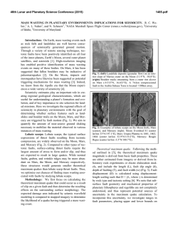
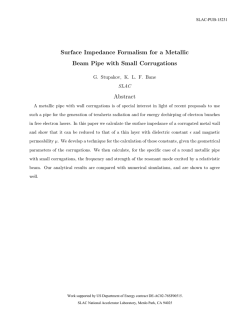
1 Analysis of Phenomena, that Affect the Distance Protection C. Gallego, J. Urresty, and J. Gers, IEEE Abstract--This article presents the impact of changes in distance protection reach and zone changes when performing simplifications in certain calculations, such as fault impedances, mutual impedances of sequence zero, grounded line in both sides and the other line in service, effect infeed and changes in sequence zero impedance because of resistivity of the ground. It also illustrates the consequences of failure to carry all zero sequence currents from other circuits coupled. These considerations are of special interest in lines without differential protection and/or with transfer trip (POTT/PUTT). Analyses were performed with the software package NEPLAN which illustrates the capabilities of these tools. Index Terms--Power System Protection, Power transmission protection, Protective relaying, Distance Protection, Mutual Impedance. I. INTRODUCTION T HIS document presents the results using advanced software tools, to analyze several phenomena associated to Distance Protection and previously recognized in the literature. Basically the benefits obtained with software, are the possibilities of making many simulations automatically for load flow and short circuit, for several operating conditions and faults; and get different automatic graphics that allow a quickly evaluation of the possible behavior of the distance relays settings during faults. Also, the software allows analyze easy and precisely the consequences of some simplifications that are frequently used, because of difficulties installing relays, unavailability of signals and use of typical data. This allows rethink and tune the settings for Distance Protection relays. Often for difficulties and for saving time, simplifications are made in the analysis and adjustment of distance relays. Some software tools include virtually all the features necessary to perform analyses without incurring simplifications or facilitating decision-making. The cases included in this document were analyzed on a real system of 115 kV. This work was supported in part by GERS S.A. C. Gallego is with GERS S.A. Consulting Engineers, Cali, Colombia, (email: [email protected]). J. Gers is with GERS USA, Weston, FL, USA (e-mail: [email protected]). J. Urresty is currently PhD student Polytechnic University of Catalonia, Terrassa, Barcelona, Spain (e-mail: [email protected]) II. CASES REVIEW Following is an introduction to concepts related with each case that will be reason for review in this document. A. Fault Impedance. It has been constant source of discussion the probable fault impedances that may present in the system. This paper will be considered different faults conditions even those that make relays see faults in zones other than those expected. There are two cases: lines fed by one side or two. One source: Multiple Sources: Line Line Load Fig. 1. Fault with impedance, one source and multiple sources. The fault occurs on the line and the behaviors of the relays located at the ends are affected by the impedance fault. The Zmeasure in one of two extremes is: Z measure = Z line + RF ( Ir I + 1) (1) Where Zline is the measured line impedance from the location of the relay to the point of failure, Rf, is the fault resistance, I is the measured contribution in the location of the relay and Ir is the current contribution from the other side of the line. If Ir is in the same phase with I, the change in Zmeasure, will only have resistive component. Usually the angles of faults currents at both sides are not equal, by example, near transformers and therefore Zmeasure will change in R and X. If only exist contribution by one side, necessarily just change R. R and X will change if exists contribution for both side. Also and necessarily, if R and X are increased at one side, will be diminished at the other end. B. Resistivity of ground – Zero Sequence Impedance The resistivity of ground (Ω-m) affects the zero sequence impedance. For resistivities of 100, 300 y 600 ohm-m, is analyzed how affect the real scope, due to this change in 2 resistivity, either by mistake to assume data or change in climatic conditions. The resistivity only affects the zero sequence impedance. The expression is: e De = 2160 f ( ft ) ( 2) Where “e” is the resistivity fault, “f” is frequency. Often used for “e” value of 100 Ω-m. De is used in the following expression De3 Z 00 = (ra + 3re ) + j0.1213Ln D D2 s eq Ω mile (3) Where ra is the resistance AC of phase conductor, re is the resistance of Carson, Ds are the Geometric Mean Ratio (GMR) of conductor and Deq is given by the following expression: C. Mutual Zero Sequence Impedance This phenomenon occurs when exist two or more lines in parallel, either in the same tower or in adjacent. This impedance allows calculate the zero sequence drop voltage in one line due to the circulation of zero sequence current on the other line. The expression is: V01 = Z 01 I 01 + Z om I 02 (6) Where V01, Z01 and I01 are zero sequence voltage, impedance and current respectively, in the circuit 1 where is the fault, Zom is the zero sequence mutual impedance and I02 is the zero sequence current for the second circuit. This is illustrated with the following cases: Vo1 Deq = Dab × Dbc × Dca 3 (4) Where Dab, Dbc and Dca, are the distances between conductors. Based on the previous equations, it can be shown that an increase in resistivity (e) in a 500%, increases the imaginary component of Z00 in 0.182 Ω/km, independent of other variables, in simple circuits without overhead ground wire. In circuits with overhead ground wire, the effect is lower, but in exchange for this, also change the resistive component. Possible zero sequence reactance in 115 kV, 230 kV and 500 kV are, 2.54 Ω/km, 1.65 Ω/km and 1.09 Ω/km respectively. This will mean that the increases in reactance are 7.1%, 11% y 17% respectively. The percent of change respect with Zoo will be a little bit lower and depend of real zero sequence impedance components. For the case of 500 kV, and for a conductor AAAC 740.8, the change in Zoo is 15.6%. Also, the short circuits levels will be changed even less, because in its calculation is involved Positive Sequence impedance, which is not change by the change in resistivity of the ground. In summary, a change in 500% in resistivity of the ground, change the zero sequence impedance in 15.6% Distance relays measure positive sequence impedance, independent of the fault type. When the fault is one phase to ground, make use of the compensation factor m, to measure correctly the positive sequence impedance. The compensation factor m, is: m= Z0 − Z1 3Z 1 Zom Zo1 Io1 Zo2 Fig. 2. Mutual coupling with same extremes Vo1 Zo1 Zom Io1 Zo2 Fig. 3. Mutual coupling, with only one same extreme Vo1 Zom Zo1 Io1 Zo2 Fig. 4. Mutual coupling, with no common end's (5) Where Z0 and Z1 are zero sequence and positive sequence total impedances per unit length. As is introduced this compensation factor, the fact to calculate with a wrong zero sequence impedance (because the change in Resistivity of ground), lead to a mistake in Positive Sequence measuring. Later this phenomenon will be discussed with an example. Ph-E Fig. 5. Mutual coupling and initial opening at one end, with another closed. And finally presents a case with multiple couplings 3 E. Infeed Effect. The literature describes very well the effect Infeed and its consequences with respect to overreaching or underreaching. Following is a brief description of this phenomenon, based on the next graphic: Line 1 Line 2 Fig. 6. Multiple mutual coupling. Node1 In the last case in particular, each transmission line will be coupled with other two in part of their pat and not at all. These couplings are also present between lines of a different level of tension, such as parallel lines, in “Right of way”, or the rare case of circuits with different level of tension in the same tower. In the last two cases there is a practical difficulty in bringing the necessary signals which can incorporate the mutual zero sequence current to relays. For purposes of illustration is presented below the own zero sequence impedances Z0 and mutual Z0m for a transmission line: Z0 = 0.1101 + j 1.0127 Ω/km Z0m = 0.06874 + j 0.5323 Ω/km The mutual zero sequence impedance change the zero sequence voltage measured at the location of the relay object of analysis. For various reasons, sometimes this impedance is not taken into account or there are technological difficulties to take it into account as in the case of parallel lines without common end. It will analyze the impact caused his noninclusion in the calculations. GEN1 Fig. 8. GEN1 causes effect Infeed to distance relay located on LINE 1 In this network, the distance relay, located in the NODE1 and protecting the LINE 1, look distorted measurement of the second zone, due to the contribution of the generator GEN1. For the network under analysis will be present several cases of very difficult solution, due the contributions and special conditions of the system. III. REVIEW AND ANALYSIS OF CASES. All cases that are presented below have been analyzed in the context of a 115 kV real system, belonging to a distribution company, which receives its power from a system of 230 kV from two different points. It also has a smaller amount (5%) own generation. Following is the single-line diagram of a part of the system to which we refer to all cases D. Mutual zero sequence impedance of grounding parallel line For various reasons it is necessary remove from service and grounding a circuit (line 2) in parallel to another circuit (line 1) that is in service. Ph-E Line 1 Line 2 Fig. 7. Line 2 grounding at their ends, serving as the way to zero sequence for faults in Line 1 Fig. 9. Part of the system. In particular the distance relay located in SUB 1, on one of two parallel lines emerging from this substation. In this case, the LINE 2 is out of service and grounding in both sides. If a one phase short circuit occurs (e.g) in LINE 1, the zero sequence current, will back not only for the overhead ground wire of LINE1 , but also for the three phases of LINE2. For practical purposes it is as if the three conductors of phase to LINE2 were overhead ground wire or neutral of LINE1. This means that the equivalent zero sequence impedance, is lower temporarily, until LINE2 not enter into service again. Will be presented later the change in scope in zone 1 derivative from not include this effect. In this system the relay that will be analyzed, is presented in the graphic, on one of two parallel lines, leaving SUB1. A. Fault Impedance. Following is the impedance seen at both ends of a line, with double source and variable impedance fault. Faults at 85% of the line were made; the impedance was modified from 0 to 100 ohm. The next figure shows how the reactance is decreasing with the resistive value, for a given fault value, the fault will be measured in Zone 2. 4 the characteristics of current and impedance, that solution did not allow high impedances faults, near the setting of first zone: 75 to 85%. For the line under analysis, here is the impedance measurement at both line sides for a failure at 50% and a variable impedance fault. The impedance data were obtained directly from NEPLAN software. TABLE I FAULT IMPEDANCES AND THEIR EFFECT ON THE IMPEDANCE MEASURED IN THE BOTH SIDES OF THE PROTECTED LINE Fig. 10. Impedance measured in the distance relay, to different fault impedances. The fault occurs at 85% of the line under analysis. The impedance in the other side of the line will be: Fig. 11. Impedance measured in the distance relay from the other side of the line of fig. 10. Fault impedance (Ω) 0 20 30 40 Impedance seen in one end (Ω) 6.70 + j 14.3 33.0 + j 13.1 45.9 + j 12.5 60.4 - j 2.74 Similar to the previous graphic, the reactance modifies its value, even take a negative value. Near to the reach of first zone, clearly there is a change of area by decreasing the impedance. At the opposite end reactance increases. The following graphic shows how the software displays the impedance for different fault locations in a line. It is similar for a fault at one point with different values of fault impedance. In this case, given that the fault occurred at 15% of the line, reactance was not enough to move to second zone. Is enough that the fault occurs at 40-50% for the reactance stay in Zone 2. Due to the first graph, usually inclines the parallelogram characteristic of first zone, as shows in the following graphic: Fig. 12. Adjustment Zones of a distance relay, which illustrates the inclination to Zone 1, because the impedance fault. The possibility that offers software to graph the trajectory of the impedance measured by the relay, it allowed to determine the inclination of the first zone. The value was 6.7 degrees. Obviously the other side does not require this inclination. Another solution to this problem has been to use an expandable mho feature. In this system of 115 kV and given Impedance seen in other end (Ω) 6.7 + j 14.32 33.0 + j 14.17 44.7 + j 15.23 57.9 + j 15.5 Fig. 13. Impedances a different distance 5 B. Ground Resistivity – Zero Sequence Impedance One of the lines in simple circuit has a length of 45 km and the next impedances of sequence, based on a resistivity of 100 Ω-m. Z1 = 9.7335 + j 21.447 Ω Z0 = 23.953 + j 68.85 Ω adjacent parallel line, not lead to relay, the positive sequence impedance will be greater than the true. For the following examples were made using a typical tower 115 kV double circuit. Excludes data detail the configuration of the tower. The impedances used for the analysis were: With a resistivity of 500 Ω-m, zero sequence impedance becomes: Z1 = 13.412 + j 28.6285 Ω Z0 = 34.72744 + j 76.725 Ω Z0m = 20.9994 + j 39.6211 Ω Z0 = 26.125 + j 74.637 Ω If it calculates the compensation factor, based on (5), and impedances for resistivity of 100 Ω-m, the value of m would be: m = 0.6941 + j 0.094 = 0.7 /7.713 Suppose we adjust the relay to its first zone has a range of 85%. This means that the setting would be: Z1 = 8.2734 + j 18.23 Ω If, for example, a fault occurs at 82% of the line, the impedance measurement (measured voltages and currents are not included, but were obtained from the test system mentioned previously) with the compensation factor m previously indicated, is: Z1 = 8.32 + j 18.28 Since this impedance is higher than setting, it is clear that there will be an underreach. In this case the underreach was only 3% over the setting value, but it is possible to have a little higher value, depending on the system characteristics. It illustrates the effect of not include the effect of mutual coupling. This effect cannot be taken into account in two ways: • In the calculations. In other words, its effect was spurned. • In the wiring. No signal is sent to the relay. The relay measures the positive sequence impedance (Z1), for a one phase to ground fault, using the following equation: Ea Z − Z1 Z Ia + ( 0 )(3I 0 ) + 0 m (3I 02 ) 3Z 1 3Z 1 Ifault(L1) (7) Where Ea, Ia, Io, are Phase-Neutral voltage, single-phase current and zero sequence current, respectively, on the line under fault; Zo, Z1 are sequence impedances; Zom is the mutual zero sequence impedance and I02 is the zero sequence current in the parallel line. If one of the last two terms is not included in the simulations or signals of zero sequence current of the = 1019.85 Amp, 3*I0 = 317.1 Amp. Vfault (L-N) = 43.32 kV, Without taking into account impedance: Ifault (L1) C. Mutual Zero Sequence Impedance Z1 = NEPLAN calculates mutual positive sequence impedances and mutual capacitances, which are really very low value, but the software uses all the data, reporting what is the impedance measured by the distance relay. The procedure for analysis consists in adjusting zones 1 without taking into account the zero sequence impedance effects and then with the software analyzes the real reach. The analysis was done using the attached system. The first zone was adjusted in 85% of its positive sequence impedance. In this case are not discussed the changes by effect Infeed, but were taken into account when adjusting the zone 1. Below are the short-circuit voltages and currents in the substation where is located the distance relay (SUB1), for a fault in the substation destination, that is, where are SOURCE2 and SOURCE1. Taking into account mutual zero sequence impedance: mutual zero sequence = 1073.6 Amp, 3*I0 = 421.03 Amp. Vfault (L-N) = 41.42 kV, These initial results allow appreciate the errors made in the simulations. Since the zones, both for three-phase faults and singlephase, are adjusted based on their positive sequence impedance, in principle are not affected by the mutual coupling, which is correct, but simulations in single-phase faults could cause erroneous conclusions. Suppose that a single-phase fault occurs on 83% of the previous line. The Z1 measure, applying (7) should be: Z1 = 11.13 + j 23.76 Ω In the case that the software is not simulating the Zom and/or in the relay has omitted the zero sequence current for circuit in parallel, the software or the relay actually measured: Z1 = 11.14 + j 24.41 Ω As can be seen in this case the reactive overreach was 2%. 6 For the same system when the fault occurs in Zone 2, the error of mutual coupling is increased because the coupling will not exist throughout the length of the line. In this case, the error was 3.5% of Infeed current from the Source 1, is out of service. The second zone settings in primary ohms, for each of the above conditions are: TABLE II ADJUSTMENTS RELAY ZONE 2 D. Mutual zero sequence impedance of grounding parallel line According to fig. 7. when grounding the parallel circuit, for aspects of maintenance or other causes, zero sequence impedance circuit of the circuit in service is amended. The new values are: Z1 = 13.412 + j 28.6285 Ω Z0 = 22.2537 + j 56.368 Ω Since the compensation factor m, included in the relay was calculated on normal service condition, the relay measured positive sequence impedance to single-phase faults, based on (7), where the only mistake would be m. The m in normal condition is: m = 0.555 /1.21 The m that really should be used for this operating condition is: R (Ω) X (Ω) Case 1 33.457 101.166 Case 2 19.932 13.088 59.572 44.813 Case 3 For each operation condition must be done the following analysis, since they've made the adjustment of each of the cases filed earlier. In other words, since it has been adjusted in ideal way, for condition 1, what happens, if it operates in each of the three possibles conditions. It is reported that the adjustment of second zone, were selected as 100% of the line protected plus 40% of the shorter line adjacent. 1) Analysis Condition 1. The table III shows that will overlap zones 2 of parallel lines, in case of absence of any of the Infeed sources. TABLE III WITH ADJUSTMENT CALCULATED UNDER CONDITIONS 1, PRESENTS THE REAL REACH, FOR EACH OPERATING CONDITIONS m = 0.307 /7.423 Condition The impedance that should measure for failure to 85% is: 1 2 3 Scope Adjacent Line Until 40% 100% 100% Parallel Line Faults between 82 and 100% Faults between 60 and 100% Z1 = 11.4 + j 24.33 Ω The erroneous impedance that is actually measured: 2) Analysis Condition 2. The table IV summarizes the reach for the settings depending on the condition 2. Z1 = 9.61 + j 21.7 Ω As can be seen, the underreach in reactance is 11%. That is, faults between 85% and 96% of the line, which should be faults in Zone 2, are in Zone 1. E. Infeed Effect. The distance relay located in the substation SUB1 on one of two parallel lines, has three intermediate sources (Infeed) that difficult the adjustment of the relay: line in parallel, national system (Source 1) and three winding transformer (Source 2). The SOURCE 2 constitutes a minor source of short circuit and therefore, the fact that sometimes this outside or in service, does not cause a strong impact on the distance relay. This case was not analyzed. We present below the possible conditions of operation of Infeed sources: • Condition 1. For the calculation of zone 2 setting, takes into account all the contributions of Infeed sources. • Condition 2. Does not take into account the contribution of Infeed current of parallel line, is out of service. • Condition 3. Does not take into account the contribution TABLE IV WITH ADJUSTMENT CALCULATED UNDER CONDITIONS 2, PRESENTS THE REAL REACH, FOR EACH OPERATING CONDITIONS Condition 1 2 3 Scope Adjacent Line Until 38% Until 40% Until 60% Parallel Line Faults between 86 and 100% Faults between 84 and 100% It will be presented problems of overreach for the condition 3. 3) Analysis Condition 3. The table V summarizes the reach for the setting depending on the condition 2. TABLE V WITH ADJUSTMENT CALCULATED UNDER CONDITIONS 3, PRESENTS THE REAL REACH, FOR EACH OPERATING CONDITIONS Condition 1 2 3 Scope Adjacent Line Until 10% Until 36% Until 16% Parallel Line Faults between 90 and 100% Faults between 88 and 100% 7 The adjustment of Zone 2 as the condition 3, not presented overreach in other conditions but the coverage is guaranteed 100% for the line protected plus a percentage of the following short line. Then taking into account the probability that the adjacent line be out of service due to maintenance is high, contrary to the SOURCE 1. As the proposed settings on condition 2 operation, only have drawback with a slight overreach in Zone 2, it is recommended adjustments Case 2. IV. CONCLUSIONS. The current software tools, as NEPLAN, allow model and get accurate results from various phenomena associated with the distance protection, this allows take right decisions if it is necessary to make simplifications due to technical difficulties, or if no data. One technical difficulty, it is to carry the signal of zero sequence of parallel circuit and in the absence of data, it could be for example, the unavailability of mutual zero sequence data. The examples given are for a system at 115 kV. Each phenomenon produces different underreach and overreach, depending on the system characteristics. Should be revised carefully the difficulty of not carrying all the signals of zero sequence couplings for faults in border adjustment. Also for systems with multiple effects Infeed, tables should be carried out to assess each situation, for different adjustment conditions. Other solution is the adaptative protection. It is necessary to have the possibility of examining the fault along the line, considering difficult faults with typical faults values. The idea here is to analyze the relay performance thoroughly. This permit force the protection and thus their resistive reach, for limits values. Finally it is recommended calculate the inclination of first zone, which only can be made in a practical way, when is perform a fault scan. V. REFERENCES [1] [2] [3] [4] [5] Phadke, Arun G. and Horowitz, Stanley H., “Power System Relaying”, Wiley Inc, 1995 Anderson P.M., “Power System Protection”, IEEE Press Series, 1999, Holmes E.J., Gers J.M., “Protection of Electricity Distribution Networks”, IEE, 2004, 2nd Edition. Blackburn, J. Lewis, “Protective Relaying: Principles and Applications”, Marcel Dekker, 1997, 2nd Edition. BCP, “NEPLAN, power system analysis software for electrical transmission, distribution and industrial networks, http://www.neplan.ch.” BIOGRAPHIES César A. Gallego S. obtained his degree in electrical engineering at the “Universidad Técnologica de Pereira”, Colombia, in 1984. En 1991 he finished his Posgraduate Studies in Power Systems at the “Universidad Nacional de Colombia”. From 1985 – 1991 he worked in the company Consultores Unidos in Bogotá Colombia, from 1993 – 2008 he work in the company GERS S.A in Cali Colombia. In GERS S.A he work in the coordination of distance relays, overcurrent relays for Industrial, transmission and distribution systems. Juan M. Gers obtained his BSc in Electrical Engineer at University of Valle, Colombia, in 1977. In 1981 he finished his MSc in Power Systems at the University of Salford in England and his PhD in 1998 at the University of Strathclyde in Scotland where he undertook a research in Distribution Systems Automation. He was the founder of GERS Consulting in 1981. He is a Chartered Engineer of IET (former IEE) and a Member of IEEE where he contributes with several groups of PSRC. Julio César Urresty Received the degree in electrical engineering in 2006 and the degree in Physics in 2008 from the “Universidad del Valle”, Cali, Colombia. From 2006 to 2008 he worked in the company GERS S.A in Cali Colombia with the software NEPLAN. In GERS S.A worked in the coordination of distance relays in a transmission system. Currently he is a PhD student in the Polytechnical University of Catalonia (UPC), in the research group MCIA (www.mcia.upc.edu) in Terrassa, Barcelona Spain.


© Copyright 2026