
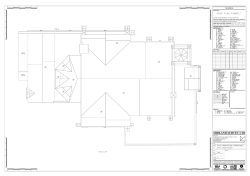
Typical Private Drainage Details
A1
CONCRETING OF DRAINS LAID
NEAR FOUNDATIONS
(as BS EN 752).
PIPE BEDDING DETAILS
INTERNAL WASTE
PIPE CONNECTION
PIPE DIAMETER
EXTERNAL R.W.P.
TO DRAIN
S.V.P. TO DRAIN
EXTERNAL R.W.P
TO GULLY
40mm Waste pipe
Soil &
Vent Pipe
4D.296 Socket plug
with 4D.399 boss
socket adaptor
When D is less than 1m, concrete
fill to level of foundation bottom.
D
100mm
10mm nominal single size
150mm
10mm or 14mm nominal single size
150mm - 500mm
10mm, 14mm or 20mm nominal single size
OVER 500
10mm, 14mm, 20mm or 40mm single size
68mm RWP
4D.149 S/S Adaptor
NB. GRANULAR MATERIAL FOR BEDDING AND
SIDEFILL TO CONFORM TO BS.882 : 1983.
4D.900 Bottle
gully
ROCKER PIPE LENGTH
PIPE DIAMETER (mm)
4D.205 Pipe
coupler
Note A:
For Dimensions and Depths
of Foundations Refer to
Structural Engineers Details
GRANULAR MATERIAL SIZE
68 mm RWP
4D.274 S/S
Access pipe
BS 8301: 1985 Code of Practise for Building Drainage
3/11.1.1
The design of Bedding for pipelines is based on the principle that
the ability of a pipe to carry a load may be increased by the
provision of suitable bedding. A rigid pipe has inherent strength but
by providing a degree of encasement higher loads may be carried.
A flexible pipe will deform under the application of loads and
requires support from surrounding material, and thus from the sides
of the trench, in order to avoid excessive deformation of the pipe.
4D.205 Pipe
coupler
4D.561 87
Degree bend
Note B:
Recognition shall be taken of the manufacturer's
recommendations in the application of the details
shown on this drawing to proprietory products.
Bend to
suit
To Chamber
CHAMBER TYPE RE
OSMA RODDING EYE
When D is 1m or more, concrete
fill to within D - 150mm of level of
foundation bottom.
x+600 max
x+300 min
4D.563
Bend
33
150
150mm side fill as
per pipe bedding
specification
Raking
length
of pipe
Equal junction
150
MIN
6D.934 or 6D.938
Concrete Protection To
Pipes Below Buildings
PIPES PENETRATING WALL /
FOUNDATIONS
3.
4.
x+600 max
x+300 min
OSMADRAIN
5.
Typical Branch
Connection
Lintel
300
BASE 6D.936
100mm bed as per pipe
bedding specification
GATIC SLOTDRAIN 100mm UNISLOT S12305
SECTION AND PLAN DETAILS ASPHALT
INSTALLATION C250 LOADING ONLY
Manhole cover & frame bedded on
mortar; BS EN 124 load class and min
opening to suit proposed installation
location and adopting organisation
Precast concrete cover slab to
BS 5911-3 and BS EN 1917.
Bedded on mortar or a
proprietary bitumen or resin
mastic sealant mortar pointing to
internal face
500mm
2-4 courses of Class B engineering clay
brick to BS 6073. Alternatively precast
concrete masonry brick and block units
to BS 6073 or precast concrete seating
rings to BS EN 1917 and BS 5911-3
Concrete to be poured up to
the level of the Wearing Course
Cast in-situ concrete strip footing.
Min 300 x 150mm thick ST4
standardised prescribed concrete to
BS EN 206-1 and BS EN 8500-2
Second pour to be done when the first
pour has sufficiently cured minimum grade
C32/40 Concrete (Elkington Gatic
recommends using 20mm aggregate)
Asphalt Wearing Course
10
Asphalt Base Course
Polystorm Access shaft
1.2m - 3.0m DEEP
Min 300mm granular material
surround to Polypipe Access shaft
Polystorm Access
turret unit
Single Polystorm unit (per layer)
omitted from Polystorm structure
construction
450mm
Polystorm
structure
100
200
100
200
BEDDING
CLASS S
Haunch Slotdrain at
feet to correct level
Granular bed
and surround
3000
1000mm
(500mm wide)
54
Concrete Bed and
Surround mix GEN3
min cover 150mm
Shallow Square
Unperforated Bucket
Asphalt to be rolled in
line with the channel
Access point
outlet box
silt box
36
Exceeding 1200
Gulley Pot 225mm
Nominal Diameter
PLAN DETAIL
Polystorm Access
base unit
18
450 - 1200
Gully Grating
Feet at ends only
First concrete pour to fix the channel to the
bottom of the trench minimum grade
C32/40 Concrete (Elkington Gatic
recommends using 20mm aggregate) to
20mm below the invert of the channel to
allow the concrete to flow underneath
Thickness of Compressible filler
(mm)
Less than 450
Asphalt to be rolled in
line with the channel
(see plan view)
Trench
10
150mm side fill
with no particle
size larger than
40mm
TABLE A - Joint filler thicknesses
Nominal diameter of
pipe (mm)
20 100
211
CHANNEL
INVERT DEPTH
To allow for possible differential movements a flexible joint
must be incorporated in each section of the pipeline within
150mm of where it enters a building or connection with an
inspection chamber, manhole wall or other structure.
ALL DIMENSION ARE IN MILLIMETRES.
This drawing is to be read in conjunction with
Appendix 5/1
Dimension X is the external diameter of the pipe
The minimum or maximum width of the trench
applies on and below a line 300mm above the
outside top of the pipe. Above the 300mm line the
trench backfill material shall be as described in
Clause 505 SHW
The concrete bed or surround may extend to the
outsides of the trench or be of minimum width.
Class 8 material is to be used to fill any voids so
formed
For Type Z trench the concrete cover may be
formed to a radius batter or horizontal surface.
Min cover of concrete shall be 150.
120
25mm Class 1 mortar haunching
to MH cover and frame
50
6.
Polystorm Access
Typical Installation Detail
100mm bed
as per pipe
bedding
specification
1.
2.
BEDDING
CLASS Z
X
150
max
NOTES
100mm min
Covering layer
X/6
100 min
600 max
Class 8 material to
S.H.W. Clause 503.3(iv)
X
D - 150
4D.163 Bend
150 mm
Sidefill
150
MIN
1250
Material to S.H.W. Clause
503.3(ii)
150
COVER & FRAME
Up to 1.2m deep use 6D.935 (450mm dia)
Over 1.2m deep use 6D.939 (350mm dia)
Branch
Connection
GEN3 concrete
surround material
825 AND OVER
Granular material to
S.H.W. Clause 503.3(i)
X/4
100 min
100
Compressible material
1000
Key
D
Main sewer
600
675 - 750
4D.360 Rodding Eye
CHAMBER TYPE NEIC
OSMA NON ENTRY INSPECTION CHAMBER
Excavated backfill
150 - 600
Pre-cast concrete
or brick base
4D.561 87 1/2
Degree bend
4D.581 87
Degree long
radius bend
ROCKER PIPE LENGTH (mm)
DO NOT ROLL OVER THE CHANNEL
TYPICAL YARD
GULLEY DETAIL
NOTE:
The responsibility to provide the
foundation design should be
that of the project engineer. the
foundation should be strong
enough to take the anticipated
loads from the largest vehicles
that will traffic the channel.
STAGE D
OSMA SILT TRAP SLB600
Top of Concrete
Fillet/Mounting block
ORIFICE CONTROL CHAMBER
NOT TO SCALE
Outlet pipe
Geosynthetic
encapsulating
Polystorm Units
300mm Square x 10mm
thick Stainless Steel
`Orifice Plate'
Min 100
Orifice Plate bolted to Concrete Fillet
mounting block with 4 NO. M12
Stainless Steel Resin/Chemical
anchor bolts, min. embedment 75mm.
Neoprene Gasket/Seal to be provided
between plate and Concrete
Ridgidrain 100mm/110mm
EN1401-1 Flange Adaptor
(Product Code: PSMFA110)
DETAIL A
ORIFICE PLATE
pipe
pipe in from
system
Orifice Plate
Orifice Plate
Level Invert
Orifice
Concrete Fillet/Mounting
block at low level to
provide flat surface to fix
Orifice Plate. Fillet
approximately 150mm
thick at its widest point
Pipe bed & surround
POLYSTORM TYPICAL
INSTALLATION DETAIL
Typical Private Drainage
Construction Details
outlet pipe to
surface water
drain
Polystorm Units
Either:
Coarse sand OR
Class 6H selected granular
material (100% passing 5mm sieve)
Highweek School
Newton Abbott
Devon
Refter to detail A
TYPICAL SECTION
NTS
NPS South West
TYPICAL PLAN
14-1-0360-RL-SD-C-200
P1


© Copyright 2026