
Köhler et al.
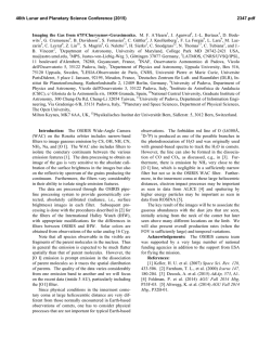
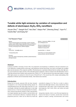
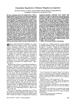
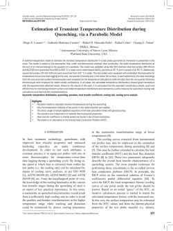
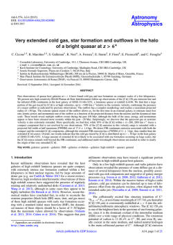
c ESO 2015
Astronomy & Astrophysics manuscript no. ms4
February 2, 2015
The Spatial Variation of the Cooling Lines in the Reflection Nebula
NGC 7023 ⋆
J. Bernard-Salas1,2 , E. Habart2 , M. K¨ohler2 , A. Abergel2 , H. Arab2,3 , V. Lebouteiller4 , C. Pinto5 , M.H.D. van der
Wiel6 , G.J. White1,7 , and M. Hoffmann2,8
1
2
arXiv:1501.07747v1 [astro-ph.GA] 30 Jan 2015
3
4
5
6
7
8
Department of Physical Sciences, The Open University, MK7 6AA, Milton Keynes, UK
Institut d’Astrophysique Spatiale, Paris-Sud 11, 91405 Orsay, France
Space Telescope Science Institute, 3700 San Martin Drive, Baltimore, MD 21218, USA
Laboratoire AIM, CEA/DSM-CNRS-Universite Paris Diderot, DAPNIA/Service d’Astrophysique, Saclay, France
Laboratoire d’Astrophysique de Marseille, CNRS/INSU Universit´e de Provence, 13388 Marseille, France
Institute for Space Imaging Science, Department of Physics & Astronomy, University of Lethbridge, Lethbridge, AB T1K 3M4,
Canada
Space Science & Technology Division, The Rutherford Appleton Laboratory, Chilton, Didcot OX11 0NL, UK
Wolfson Brain Imaging Centre, Addenbrooke´s Hospital, University of Cambridge, Cambridge, CB2 0QQ, UK
Received date / Accepted date
ABSTRACT
Context. The north-west photo-dissociation region (PDR) in the reflection nebula NGC 7023 displays a complex structure. Filamentlike condensations at the edge of the cloud can be traced via the emission of the main cooling lines, offering a great opportunity to
study the link between the morphology and energetics of these regions.
Aims. We study the spatial variation of the far-infrared fine-structure lines of [C II] (158 µm), [O I] (63 and 145 µm). These lines trace
the local gas conditions across the PDR. We also compare their emission to molecular tracers including rotational and rovibrational
H2 , and high-rotational lines of CO.
Methods. We use observations from the Herschel/PACS instrument to map the spatial distribution of these fine-structure lines. The
observed region covers a square area of about 110′′ x110′′ with an angular resolution that varies from 4′′ to 11′′ . We compare this
emission to ground-based and Spitzer observations of H2 , Herschel/SPIRE observations of CO lines, and Spitzer/IRAC 3.6 µm images
that trace the emission of polycyclic aromatic hydrocarbons. We use a PDR code to model the [O I]145µm line, and infer the physical
conditions in the region.
Results. The [C II] (158 µm) and [O I] (63 and 145 µm) lines arise from the warm cloud surface where the PDR is located and
the gas is warm, cooling the region. We find that although the relative contribution to the cooling budget over the observed region is
dominated by [O I]63 µm(>30%), H2 contributes significantly in the PDR (∼35%), as does [C II]158 µm outside the PDR (30%). Other
species contribute little to the cooling ([O I]145 µm 9%, and CO 4%). Enhanced emission of these far-infrared atomic lines trace the
presence of condensations, where high excitation CO rotational lines and dust emission in the submillimitre are also detected. The
[O I] maps resolve these condensations into two structures, and show that the peak of [O I] is slightly displaced from the molecular
H2 emission. The size of these structures is around 8′′ (0.015 pc), and in surface cover about 9% of the PDR emission. We have
tested whether the density profile and peak densities derived in previous studies to model the dust and molecular emission, can
predict the [O I]145 µm emission. We find that the model with a peak density of 106 cm−3 , and 2×10⁴−5 cm−3 in the oxygen emitting
region, predicts an [O I]145 µm line which is just 30% less than the observed emission. Finally, we have not detected emission from
[N II]122 µm, suggesting that the cavity is mostly filled with non-ionised gas.
Key words. Infrared: general – photon-dominated region (PDR) – ISM: lines and bands – ISM: individual objects – NGC7023
1. Introduction
NGC 7023 is a bright and well-known reflection nebula.
Although it is a relatively nearby object, its reported distance
varies significantly in the literature. Using Hipparcos parallaxes
van den Ancker et al. (1997) and later on van Leeuwen (2007)
measured a distance of 430+160
−90 pc and 520±180 pc respectively,
and Benisty et al. (2013) estimated a distance of 320±51 pc
based on revised orbital parameters and astrometry. In this paper we adopt the distance given by van den Ancker et al. (1997)
Send
offprint
requests
to:
J.
Bernard-Salas,
e-mail:
[email protected]
⋆
Herschel is an ESA space observatory with science instruments
provided by European-led Principal investigator consortia and with important participation from NASA.
(430 pc), which is almost the average of the values given by
van Leeuwen (2007) and Benisty et al. (2013).
It is excited by the Herbig Be binary star system HD 200775
(Alecian et al., 2008), which is immersed in the cavity of the
molecular cloud (Fuente et al., 1992). The overall morphology
of NGC 7023 is driven by the action of the ionising stars, where
the stellar outflow, now inactive, creates a biconical cavity in
the shape of a butterfly of about of 1.5 pc× 0.8 pc in size
(K¨ohler et al., 2014). The stars illuminate the walls of the cavity in an almost edge-on orientation. At the edge of these walls,
three PDRs are present (Fuente & Mart´ın-Pintado, 1997), and
are located at 40′′ northwest (herein NW), 70′′ south-west (SW),
and 170′′ east of the stars. The NW PDR is the brightest, and
is oriented almost edge-on to the observer. Polarization observations in the near-infrared (Sellgren et al., 1992), as well
1
Bernard-Salas et al.: Cooling lines in NGC 7023
as vibrational H2 (Lemaire et al., 1996) of the NW PDR reveal a filamentary morphology. Witt et al. (2006) find that this
morphology is the result of several condensations that are superimposed along the line of sight, whose surfaces are directly illuminated by the star. The incident radiation field, in
units of the interstellar far-ultraviolet radiation field estimated
by Habing1 , is G =2.6×10³ (Chokshi et al., 1988; Pilleri et al.,
2012). However, higher values also having been reported in the
literature (Fuente et al., 1999). Deriving the incident radiation
field relies on several assumptions on the geometry and spectral type of the star. For the rest of the paper, we will assume
the value of G =2.6×10³ at the PDR front as in Chokshi et al.
(1988) and Pilleri et al. (2012).
NGC 7023 has been the subject of many studies in the literature, including several spectroscopic studies in the mid- and
far-infrared (FIR). The mid- and far-IR spectral regions contain many important cooling lines and hold the fingerprints
of the dust emission. Fuente et al. (2000) presented ISO/SWS
and LWS observations of NGC 7023 and differentiated between
three regions: 1) the star and the cavity formed by the star, which
is filled with a low density gas, 2) the edges of the cavity that
defines the PDRs, and 3) the molecular gas. Based on their analysis of the atomic and molecular lines ([O I]63 µm, [O I]145 µm,
[C II]158 µm, H2 ), they find that the NW and SW PDRs have
similar excitation conditions, with filaments having a high density of n ∼106 cm−3 , and a lower density of n ∼104 cm−3 in
the region between filaments. Werner et al. (2004) and, later on,
Sellgren et al. (2007) studied the variation of the dust features
in the mid-IR spectrum of NGC 7023 using the Spitzer/IRS and
MIPS instruments. They observed variations in the NW and SW
PDRs of the intensity, widths, and central wavelength of spectral
features arising from polycyclic aromatic hydrocarbons (PAHs),
as a function of the distance to the ionising source (HD 200775).
Witt et al. (2006) found a good correlation between the optical emission from the dust, as traced by the R band (658 nm),
with that of ro-vibrational H2 . Using Spitzer data, Fleming et al.
(2010) studied the H2 and PAHs emission in the PDRs of three
reflection nebulae, including NGC 7023. They showed evidence
for PAH de-hydrogenation, which they concluded is suggestive
of H2 formation on PAHs.
Recently, NGC 7023 has been the target of several programs
using the Herschel Space Observatory (Pilbratt et al., 2010),
vastly improving the spatial resolution of previous far-infrared
studies. Abergel et al. (2010) combined Spitzer and Herschel
maps to study the spatial variations of the dust properties in
the east PDR. Using a radiative transfer code they were able
to reproduce the different spatial variations of PAHs, very small
grains (VSGs), and large dust grain emission. Joblin et al. (2010)
used the high spectral resolution provided by the HIFI instrument to study the [C II]158 µm line at several positions in the
nebula, including a central position in the NW PDR. They found
that the emission of [C II]158 µm line and PAHs arises from
the transition region between the atomic and molecular gas.
Okada et al. (2013) studied the photoelectric efficiency from
PAHs in a sample of six PDRs, including the East and NW
PDRs of NGC7023. Using Spitzer and Herschel/PACS observation, they evaluate the photo-electric effect from PAHs and
the cooling [O I]63 and 145 µm, and [C II]158 µm lines in three
regions (cavity, interface, and molecular region) and find that regions with high fraction of ionised PAHs have a lower heating
efficiency.
1
The Habing field corresponds to 1.6×10⁻³ erg s−1 cm−2 when integrated between 91.2 and 240 nm (Habing, 1968).
2
Fig. 1. Overlay of the PACS field of view on a ground based H2
1-0 S(1) map at 2.12 µm (Lemaire et al., 1996). A 3×3 raster
map was performed (see Sect. 2). The map covers an area of
approximately 110′′ x110′′ and is centred in the NW PDR. The
emission from the ionising stars (HD 200775), on the bottom left
of the figure, is saturated. RA and Dec coordinates are in degrees
(J2000)
In this paper we present observations from the
Photoconductor Array Camera and Spectrometer (PACS,
Poglitsch et al., 2010) of the [O I]63 µm, [O I]145 µm, and
[C II]158 µm lines in the NW PDR of NGC 7023. These observations allow us to resolve in detail the global shape of the PDR,
although substructures such as the filaments observed at higher
spatial resolution (e.g., Lemaire et al., 1996; Fuente et al. ,
1996), are unresolved. This study complements a recent SPIRE
spectroscopic study of the molecular gas and dust emission
by our group (K¨ohler et al., 2014). This paper is organised as
follows: the observations and data reduction are described in
Sect. 2. In Sect. 3 the spatial morphology of the lines, their
comparison to the emission of CO and H2 , and the correlation
between the different line ratios as a function of the distance to
the ionising source, are discussed. In Sect. 4 the cooling budget,
and the morphology of the main cooling lines are analysed. In
Sect. 5 the results of the modelling are described. Finally, the
conclusions are summarised in the final section.
2. Observations and Data Reduction
The observations were carried out during the science demonstration phase (SDP) of Herschel on 7 January 2010, and are part
of the ”Evolution of the Interstellar Medium” guaranteed time
key project (observation ID=1342191152, Abergel et al., 2010).
The observations were taken using the PACS instrument in the now decommissioned - wavelength switching mode. Four finestructure lines were observed: [C II] at 158 µm, [O I] at 63 and
145 µm, and [N II] at 122 µm. The observations were centred on
the NW PDR, with RA and DEC coordinates of 315.375◦and
60.178◦respectively (J2000).
The observing strategy and reduction methods follow that of
our earlier paper on the Orion Bar (Bernard-Salas et al., 2012).
Bernard-Salas et al.: Cooling lines in NGC 7023
We thus summarise the main steps here, and refer to the above
paper for details.
To trace the NW PDR a 3x3 raster map was performed. The
configuration at the time of the observation is shown in Fig. 1,
where the raster map at the epoch of observation is overlaid on
top of an H2 map of the region made with the Canada-FranceHawaii Telescope (CFHT). An additional map centred in the
East PDR (not shown in the figure) will be presented in a future paper. A minimum exposure configuration of one cycle and
repetition per line was performed. Raster and point line steps of
23.5′′ were chosen and result in Nyquist sampling for the lines
in the red channel ([C II]158 µm, [O I]145 µm, [N II]122 µm).
The purpose of the wavelength switching mode is to cancel
out the background by determining a differential line profile.
This means that observations at an off-position are not needed
to remove the background in such mode. The present observations of NGC7023 were deemed to have calibration value by
the Herschel Science Center, and it was decided to obtain an
additional set of observations at the centre position so that the
PDR would be observed with a higher S/N. This was achieved
by including an off-observation in the astronomical observation
request (AOR), to be performed after three raster positions and
with zero offset relative to the centre of the map. This resulted in
the centre of the map being observed a total of 3 times, with the
redundancy resulting in a higher S/N for that central position,
which is centred in the PDR.
The data were processed using version 6.0.3 of the reduction and analysis package HIPE (Ott, 2010). Each raster position, or footprint, consists of 5×5 spectral pixels (called spaxels). HIPE produces a data cube for each footprint, which contains a spectrum for each spaxel. Starting from level 1 the cubes
were further processed, using proprietary tools, to correct for
minor drifting effects and flux misalignments between scans. At
this point the cubes are exported into the software PACSman
(Lebouteiller et al., 2012) to measure the line fluxes by fitting
a Gaussian, and create the final map. The uncertainties in the
line fluxes are small and on average amount to less than 5%
for the [C II] and [O I] lines. The relative flux accuracy between spaxels is 10%2 , and for the remaining of the paper we
have adopted this value or the uncertainty from the fit given
by PACSman, whichever is higher. Note that we do not detect the [N II]122 µm line at any position in the map. The final integrated intensity maps of the [O I]63 µm, [O I]145 µm, and
[C II]158 µm lines are shown in Fig. 2.
We have compared our measurements of the [C II] line with
the fluxes measured by Joblin et al. (2010) using the HIFI instrument, and the ISO/LWS measurements by Fuente et al. (2000).
all compared to the largest beam. The position used for comparison (RA=315.385◦, DEC=68.1743◦) is located in the clump of
enhanced emission and is marked at the top right panel of Figure
2 with a plus symbol. All measurements agree within ∼10 %.
Okada et al. (2013) observed the same lines in the NW PDR.
Their observations consists of a single pointing, while our observations perform a detail mapping of the region to show the
morphology of these lines, providing a complete coverage of the
region and allowing for better calibration. We have compared our
fluxes to that of Okada et al. (2013) in the cavity, interface, and
molecular region. These three positions are marked with squares
in the top right panel of Figure 2. All values agree within 29%,
where the [C II]158 µm and [O I]145 µm fluxes in the interface,
2
From
the
PACS
spectroscopy
performance
and
calibration
manual.
This
can
be
found
at
http://herschel.esac.esa.int/twiki/bin/view/Public/PacsCalibrationWeb
and the [O I]63 µm flux in the molecular region agree within 5%.
The uncertainty in the Okada et al. (2013) paper is of ∼30%,
while in our work is typically <10%, and thus both values are
consistent within the uncertainties.
In addition to the atomic lines presented in this paper, we
compare in Section 4 their emission to other relevant cooling
species of CO, H2 O, CH+ , and C0 . In particular, we use the CO
4<Ju <13 transitions in the SPIRE range, and the rotational lines
of H2 0-0 S(1), S(2), and S(3) at 17.0, 12.3, and 9.7 µm from
the Spitzer data. We also use the 360 and 609 µm lines of C0
(SPIRE). Since we do not detect any CH+ and H2 O lines in the
SPIRE range, we derive an upper-limit to the transitions of these
species that were detected in the Orion Bar (Bernard-Salas et al.,
2012). These observations were taken from Pilleri et al. (2012)
for H2 lines, and K¨ohler et al. (2014) for the SPIRE lines.
3. Spatial Distribution
3.1. Cooling Lines
The three top panels in Fig. 2 show the observed distributions of the [O I]63 and 145 µm, and [C II]158 µm lines. The
exciting source, the binary system HD 200775 (RA=315.404◦,
DEC=68.1633◦), illuminates the PDR from the lower left side
of the figure (just outside the maps, see also Fig. 3). For each
panel the beams are shown in the lower left corner and represent
sizes of 4.5′′ , 8.8′′ , and 11′′ from left to right respectively. In
this scale, and adopting a distance of 430 pc to NGC 7023, 10′′
corresponds to a physical scale of 0.02 pc.
The PDR is detected in the three lines. Their emission arises
from the surface of the clouds, where the gas is warm (∼700K70K, Fuente et al., 1999; Fleming et al., 2010; K¨ohler et al.,
2014). There is also evidence for condensations of enhanced
emission within the PDR, where both [O I]63 and 145 µm line
maps can resolve two structures (red clumps in the figure). This
is the first time in NGC 7023 that such structures have been revealed from the emission of the [C II]158 µm and [O I]63 and
145 µm lines within the PDR. These structures or knots are directly illuminated by the star, and coincide with the presence
of highly-excited CO lines and dust emission (see next section). These clumps are better delineated in the [O I]145 µm map
(Figure 2), which reveals two distinct clumps, and a possibly
third fainter clump. The size of the main structures is around 8′′
(0.015 pc at the distance to NGC 7023). While it is possible that
these clumps may not be yet be resolved in our observations, we
find that these clumps cover 9% of the PDR surface area, where
in this case we consider the PDR area to be any [O I]145 µm flux
greater than 0.9×10⁻⁷ W m−2 sr−1 (red, green, and blue colours
in the upper middle-panel of Fig. 2).
The PDR is well delineated in the [O I]145 µm line
(Fig. 2). Further away from HD 200775, the emission of
[O I]145 µm drops to zero. The spatial distribution of the
[O I]63 µm line is similar, although the emission is more extended than that of the [O I]145 µm line. This is expected as the
[O I]63 µm line becomes optically thick at lower column densities than the [O I]145 µm line, and once saturated, its emission will be broader (Caux et al., 1999). The [C II]158 µm emission is even more extended, since it is easily excited. This
was also seen in a similar study by our group on the Orion
Bar (Bernard-Salas et al., 2012). The figure also shows that
the morphology of the [C II]158 µm line is complex and
structured. Using Herschel/HIFI high-resolution spectra of the
[C II]158 µm line, Joblin et al. (2010) and Bern´e et al. (2014, in
prep.) detect different components with a large distribution of ve3
Bernard-Salas et al.: Cooling lines in NGC 7023
22.40
5.43
10.10
16.87
4.08
7.60
11.33
2.72
5.10
5.79
1.36
2.60
0.25
0.00
0.10
19.19
5.18
10.10
14.50
3.88
7.79
9.82
2.59
5.48
5.14
1.30
3.17
0.45
0.00
0.86
Fig. 2. The upper three figures show the observed images for the [O I]63 µm, [O I]145 µm, and [C II]158 µm lines. The lower panels
show combination of lines with contour maps over-plotted in white. The bottom images have been convolved to the 158 µm (largest)
beam, with the beam size illustrated in the bottom left of each panel. The squares and plus symbols in the upper right panel indicate
the positions used to compare the [C II]158 µm flux to previous measurements in the literature (see Sect. 2). All maps are in flux
units of 10−7 W m−2 sr−1 . The eight highest contours are at 100, 91, 82, 74, 65, 56, 47, and 38% of the peak emission.
locities, indicating that besides the main filaments, other regions
are contributing to the [C II] emission.
In the lower three panels of Fig. 2 we plot different combinations of lines and their contours convolved to the largest
beam size (11′′ ). It can be seen that both of the [O I] lines correlate spatially very well with each other (lower left panel). The
middle bottom panel shows that the [C II] emission also delineates the PDR but with a more complex structure than the
[O I]145 µm line. The peak emission is slightly displaced and
broader in the [C II] line than the [O I]145 µm. This is better seen in the last panel where the concentric contours of the
[O I]63 µm line contrasts with the more irregular emission of
[C II], including a peak of emission with a heart-shape structure.
Finally, as mentioned in the previous section, no [N ii] line
at 122 µm was detected in the PACS map. The 205 µm line was
also not detected in the SPIRE maps (K¨ohler et al., 2014). Using
HIFI observations that include the ionising stars, the Herschel
Warm and Dense ISM program (WADI, Ossenkopf et al., 2011)
detects ionised emission only from a shell close to the stars (private communication), an area just outside our observed map.
This could indicate that the gas in the cavity near the PDR is
mostly neutral and not ionised, and explains why we do not detect the 122 µm line since our map does not include this region
close to the ionising stars. Alternatively, if the density is too low
in the cavity (Fuente et al., 2000) its emission will be too weak
to detect in our observations. We have derived an upper-limit to
the flux for this line of 1.1×10⁻⁷ W m−2 sr−1 .
4
3.2. Comparison with CO, H2 , and PAH emission
Fig. 3 (left) displays a high-resolution CFHT image of the H2
1-0 S(1) molecular line at 2.12 µm (Lemaire et al., 1996), which
reveals in detail the filamentary structure of the region. Overplotted in white and red respectively are contours of the [O I]
145µm line and one of the excited rotational 12 CO line (J=1211) measured in the SPIRE data by K¨ohler et al. (2014). We
note that the images are not convolved as the purpose of this
panel is to place the emission of [O I] 145 µm line and warm
CO relative to the filaments. The right panel of the figure shows
the Spitzer H2 0-0 S(3) 9.7 µm map convolved to the 145 µm
beam, with white [O I]145 µm contours. The H2 0-0 S(3) transition follows the same distribution as the 1-0 S(1), but being
pure rotational line it peaks slightly behind (∼1.9′′) the 1-0 S(1)
transition. These observations show for the first time that the
[O I]145 µm emission in NCG 7023 is displaced with respect to
the bright filaments that are seen in H2 . The reason for this is that
since the H2 emission closely traces the UV field, its emission
peaks at the edge of the PDR, while the [O I] 145 µm is more
sensitive to both the gas density and temperature. K¨ohler et al.
(2014) have recently mapped the emission of high excitation CO
lines in the region. It can be seen that this highly excited CO
emission (left panel in Fig. 3) is located at the same position as
the [O I] peak. We note that the 12 CO J=12-11 line peaks at the
same position as the also observed 13 CO J=7-6 line. Similarly,
although not shown, these condensations are also detected in
Herschel/SPIRE and IRAM submillimitre maps that trace dust
emission (K¨ohler et al., 2014).
Bernard-Salas et al.: Cooling lines in NGC 7023
5.0
14.7
3.6
11.0
2.2
7.4
0.8
3.7
-0.6
0.0
Fig. 3. Left panel: Spatial correlation of the H2 1-0 S(1) emission map at 2.12 µm (Lemaire et al., 1996) compared to the [O I]
(145µm) and 12 CO J=12-11 (K¨ohler et al., 2014) contour maps in white and red respectively. To better illustrate the filaments these
images have not been convolved to the largest beam (in this case, CO). The two orange symbols (squares) mark the position where
the high excitation CO lines are detected (A), and a nearby position with similar conditions but showing no highly excited CO
emission (B). These positions are discussed in Sect. 3.2. Right panel: H2 0-0 S(3) map at 9.7µm convolved to the [O I] 145µm beam
with its contours in white. In both panels the colour bar intensities are in units of 10−7 W m−2 sr−1 , where the four highest contours
have values of 5.4, 4.7, 3.9, and 3.1 for [O I]145 µm, and of 0.37, 0.3, 0.2, and 0.1 for the CO.
It is interesting to explore the origin of this highly excited
CO in relation to the atomic cooling line emission. For this purpose, and to guide the discussion in the next section, we have
selected two regions: one coinciding with the CO J=12-11 peak
(position A), and a nearby region with no high-J CO emission
(B). We note that low-J emission is detected in positions A and B
(K¨ohler et al., 2014). Both positions are labelled in Fig. 3. The
[O I]145 µm flux and the [O I]145 µm/[C II]158 µm ratio in position A is respectively 2.2 and 1.7 higher than in position B.
Although small, these differences are real (larger than the associated uncertainties in the [O I]145 µm flux and ratio), and indicate variations in the physical conditions between the two regions considered. Such differences can be achieved by changes
in the radiation field and/or density of a factor ∼3 in standard
PDR grid models (Kaufman et al., 2006). How can such small
differences explain the presence of high-excited CO in position A? The emission of highly excited CO can be explained
by changes in the gas density if a certain threshold in the conditions is reached. K¨ohler et al. (2014) derived a density of 5×10⁴ –
106 cm−3 and a temperature ranging between 65–130 K at position A, while at position B they found a lower density (104 –
105 cm−3 ) and T=80–120 K. The critical density of the CO lines
(105 –107 cm−3 for J=4-3 to 13-12 transitions) is higher than the
[O I] lines (∼105 cm−3 ). This means that, in the density regime
between 104−6 cm−3 , the CO lines are more sensitive than the
oxygen lines to an increase in density which could boost the CO
emission while having little effect on the atomic line emission.
It is thus possible that differences in densities in the two positions could thus explain the presence of highly excited CO in the
clumps.
Because of the low ionisation potential required to ionised
carbon (11.3 eV), the [CII] 158 µm line can arise from both the
neutral (i.e. PDR) and the ionised medium. To validate its use
as star formation indicator, it is interesting to compare the [CII]
emission with other known tracers of the star formation process,
like PAHs (Peeters et al, 2004). In Fig. 4 we make such comparison where we plot the PAH emission traced by the Spitzer/IRAC
3.6 µm band with the [C II]158 µm contour map. Despite the
the fact that the [C II]158 µm line includes emission from different velocity components, it can be seen that the [C II] line
follows reasonably well the PAH emission, with the peak of
[C II]158 µm emission (heart-shaped) coinciding with the PAH
filament. Whichever regions contribute to the [C II]158 µm emission, these must be (mostly) PDR dominated since it traces the
PAH emission.
3.3. Line Correlations and Ratios
Different lines and line ratios have been plotted against each
other as a function of the distance to the ionising stars HD 20077
in Fig. 5. Panel a in this figure highlights the different regions
we consider. These include regions in front of and behind the
PDR, which in subsequent panels are shown as blue and red
dots respectively. In the figure the plus symbols are PDR points
with a flux higher than 75% of the [O I]145 µm peak emission
and are delineated by the black contour. Also shown are selected points from an adopted cut across the PDR starting from
HD 200775 (labeled numbers). The latter are shown with their
error bars to illustrate the flux uncertainty in different regions of
the map. The variation in the flux intensities across the PDR of
5
Bernard-Salas et al.: Cooling lines in NGC 7023
Fig. 5. Intensity plots for different combinations of line fluxes (in 10−7 W m−2 sr−1 ) and line ratios relative to other lines or distance
to HD 200775. All fluxes have been convolved to the largest beam (11′′ ). The different regions are indicated in the convolved
[O I]145 µm map in the first panel and are labelled in the second, where blue represents points in front of the PDR, and red those
behind it. The peak emission in the PDR is delineated by the black curve in the first panel (those with [O I]145 µm fluxes higher
than 75% of the peak intensity of the line), and are plotted as plus symbols in the subsequent panels. The reference points for the
adopted cut are numbered and shown in the first panel (Sect. 5), and have been plotted as black dots with error bars in subsequent
panels to give an indication of the uncertainties.
the [C II]158 µm, and [O I]63 and 145 µm lines is larger than a
factor 10, which is higher than those observed in the Orion Bar
(factor <7) for the same lines (Bernard-Salas et al., 2012).
cause of the multi-component [C II]158 µm emission, there is a
broader relation in the ratio.
Panels b and c show respectively the relation between [C ii]
and [O I]63 and 145 µm lines. There is a broad correlation in
front of and after the PDR in both plots. The likely reason for
the broad relation is the mixture in the line of sight of the different components that give rise to the [C II]158 µm line (see
Sect. 3). The relation in panel c is somewhat narrower than in
panel b. This could be attributed to the fact that the emission of
the [O I]63 µm line, being optically thicker than the [O I]145 µm,
is also extended and follows the [C II]158 µm emission more
closely.
4. Cooling budget
Panel d shows a linear correlation between the [O I]63 and
145 µm lines behind the PDR, and a more parabolic relationship
in front of it. In front of the PDR the gas is warmer and optical depth effects become more important. Having an Einstein
coefficient five times higher, the [O I]63 µm line will be more
self-absorbed than the [O I]145 µm line, and its overall emission
will be more extended. Therefore, in that region [O I]145 µm increases more than the [O I]63 µm line does.
In the last two panels in the figure (e and f), the
[O I]145 µm/[C II]158 µm and [O I]145 µm/[O I]63 µm ratios are
plotted respectively against the distance to HD 200775. As we
approach the PDR the density increases and both line ratios increases rapidly, peaking at around 45′′ . After the PDR, the temperature drops and both line ratios decrease. However, and be6
The mid- and far-IR regions are home to the most important
cooling lines in the PDR. Our Herschel observations, together
with Spitzer data, have enabled us to estimate the importance of
these species to the cooling budget. We have thus derived the
contribution of the [C II] and [O I] cooling lines in the PDR, as
well as other relevant atomic and molecular lines in the mid- and
far-IR including; CO, H2 , and C0 . H2 and CO are the most abundance molecular species in the ISM and contribute also to the
cooling in PDRs (Hollenbach & Tielens, 1999). To calculate the
budget of these species we consider the 0-0 S(1), S(2), and S(3)
rotational lines of H2 at 17.0, 12.3, and 9.7 µm (Spitzer/IRS),
and CO 4≤ Ju ≤13 transitions (SPIRE). In the Orion Bar, C0 ,
CH+ and H2 O lines are detected in the PACS and SPIRE spectra and contribute ∼1% of the total cooling budget (Habart et al.,
2010; Bernard-Salas et al., 2012). This is a small factor to the
total cooling budget in the Orion Bar, but we have explored their
contribution in NGC 7023 as well. We have detected the 370
and 609 µm lines of C0 in the SPIRE spectrum (K¨ohler et al.,
2014). We do not detect CH+ and H2 O transition in the SPIRE
spectrum of NGC7023 so have derived upper-limits for their farIR transitions to estimate their contribution. For this comparison
we choose the position of the [O I] emission peak in the PDR
(red knots in Fig. 2), and we convolve all the line emission to
Bernard-Salas et al.: Cooling lines in NGC 7023
148.4
111.3
74.2
37.1
0.0
Fig. 4. Comparison of the PAH morphology as traced by the
IRAC 3.6µm band intensity in MJy/sr (taken from the Spitzer
archive), with [C II] 158 µm in white contours. In decreasing order the contour levels are at 10.1, 9.0, 7.8, 6.7, 5.6, 4.5, 3.4, and
2.2 ×10⁻⁷ W m−2 sr−1 .
′′
the largest beam, in this case the SPIRE CO emission (25 ). In
Table 1 we quote these values together with those of the Orion
Bar (Bernard-Salas et al., 2012), which is usually adopted as the
prototypical PDR.
Table 1. Cooling line emission as a percentage at the PDR position and convolving the emission of all species to a 25 beam.
[C II] 158 µm
[O I] 63 µm
[O I] 145 µm
[C II] + [O I]
H2
CO
C0 , H2 O, CH+
†
NGC 7023
19
33
9
61
35
4
<1
Orion Bar†
8
72
10
90
5
5
<1
From Bernard-Salas et al. (2012).
Table 1 shows that in the NW-PDR of NGC 7023 the cooling budget is dominated by the [C II]+[O I] (61%), followed by
H2 with 35%, CO (4%), and C0 contributing less than 1%. The
uncertainty in these percentages is around 20% of each value.
The main contributors to the cooling budget are [O I]63 µm and
H2 . The overall result is similar to that found in the Orion Bar,
where the atomic lines dominate the cooling line emission, with
[O I]63 µm being the strongest. However, the main difference is
the reduced role of H2 in the Orion Bar (5%) when compared to
NGC 7023. As part of the same program, we have studied nine
other nearby PDRs and find that, like for NGC 7023, H2 contributes to about 30% (Bernard-Salas et al. in prep.).
In Figure 6 we show the relative contribution by percentage of the [O I]63 and 145 µm, and [C II]158 µm lines, along
with that of H2 . For H2 we consider the 0-0 rotational transitions S(1), S(2), and S(3) and the vibrational line v=1-0 S(1). All
maps have been convolved to the [C II]158 µm beam. Thus, for
a given point in the map, the total cooling of these four species
amounts to 100 %. Therefore this figure shows which species
dominates the cooling in different regions. We ignored the contribution of C0 , H2 O and CH+ , but as we can see from Table
1, their contribution is already negligible in the PDR, where we
would expect their contribution to be strongest. If we first look at
each map individually, we see that [O I]63 µm contributes more
in front of the PDR, and [C II]158 µm outside it (in front and
behind). [O I]145 µm and H2 contribute more in the PDR, but
with [O I]145 µm contribution being higher in the south-east region (lower-right). The [O I]145 µm line is more sensitive to the
gas density than the H2 lines, and thus contributes more where
the clumps are located. Reading the percentage from the colour
bars, we can also compare the relative contribution amongst each
other. In general, [O I]63 µm is the dominant contributor over the
entire region (>30%). However, [C II]158 µm is also an important coolant outside of the PDR (contributing above 30%), as is
H2 in the PDR (>35%). On the other hand, the contribution of
[O I]145 µm does not exceed 12% in the PDR and is lower than
5% in the rest of the region. This figure delineates the importance of [O I]63 µm, [C II]158 µm, and H2 as cooling agents as a
function of the region.
5. Modelling
In this section our goal is to explore whether previously reported
parameters used to model the dust emission in the PDR (density
profile, geometrical parameters), and CO lines (gas physical conditions), can also reproduce the [O I]145 µm emission. This is
important in our quest to find a model that can self-consistently
reproduce the dust, molecular, and atomic PDR components.
Using Herschel photometry and spectroscopy, the dust emission
and molecular content (CO) of the NW PDR has been recently
modelled by Arab et al. (2012) and K¨ohler et al. (2014). In our
observations the [C II]158 µm line is a mixture of many components, the emission of the [O I]63 µm line is optically thick, and
the [N II]122 µm was not detected. Thus, attempting to model the
atomic component from our observations will serve to provide
basic physical conditions of the PDR based on just fitting the
[O I]145 µm line. This is why we prefer instead to test whether
previously and more detailed modelling studies can also explain
the [O I]145 µm emission.
In order to model the emission of the line we have selected a
cut originating from the ionising stars and intersecting the NW
PDR at a point of peak dust emission at 250 µm. This is the same
cut used in (K¨ohler et al., 2014) for the molecular line and dust
emission. The observed emission profiles for the three lines, together with that of the H2 1-0 S(1) and CO J=12-11 lines, are
shown in Fig. 7 (left panel). These profiles are shown at their natural resolution to maximise the spatial information we can obtain
from them. It can be seen that [O I]63 and 145 µm, [C II]158 µm,
and CO J=12-11 peak at the same position. Having the highest spatial resolution, the H2 profile resolves two filaments (see
Fig. 3), with the densest filament peaking immediately in front
of the fine-structure and CO lines relative to the external illumination. The [C II]158 µm line has the broadest profile, followed
by [O I]63 µm.
We have modelled the emission of the [O I]145 µm line
with the Meudon PDR radiative transfer code (version 1.4.4,
Le Petit et al., 2006; Le Bourlot et al., 2012). This code assumes
a plane-parallel slab of gas and dust that is illuminated by an in7
Bernard-Salas et al.: Cooling lines in NGC 7023
45
12
37
9
29
6
21
4
13
1
52
60
43
48
35
36
27
25
18
13
Fig. 6. Relative cooling budget of the [O I]63 and 145 µm, [C II]158 µm lines, and the 0-0 S(1), S(2), S(3) H2 rotational transitions
and v=1-0 S(1) in percentage (%). Adding the contribution of all four species for a given point in the map amounts to 100 %. Other
species that can contribute to the cooling are ignored in this figure (see Sect. 4). In the first panel, and to guide the eye, a contour of
the PDR as traced by the [O I]63 µm emission is shown. The images have been convolved to the largest of the beam sizes of these
species, in this case the [C II]158 µm line, shown as a solid circle in the [CII] panel. In addition, and for comparison, we also show
the largest CO beam size (25′′ ) used to calculate the cooling budget in Table 1 as a dashed circle .
cident radiation field, and resolves iteratively the radiative transfer and thermal and chemical balance to compute the atomic and
molecular emission in the cloud. As in the papers listed above,
we have assumed an incident radiation field of G∼2,600 on the
NW PDR at 42” from the star (Chokshi et al., 1988; Pilleri et al.,
2012). The RADEX analysis of the CO lines (K¨ohler et al.,
2014), and the modelling of the dust emission are compatible
with two maximum gas densities of 105 and 106 cm−3 . Thus,
for our comparison we consider both possibilities. These studies
derive a PDR length of 0.2 pc for a gas density 105 cm−3 and
0.03 pc for a density of 106 cm−3 , giving both a total column
density of about 1022 cm−2 , and we adopt these values in our
study. We assume the density profile derived from the dust analysis and adjusted to start at 0.088 pc (42′′ ) from HD 200775. The
density profiles for the two gas densities we consider are shown
in the middle panel of Fig. 7. We hereafter refer to these models as model 1 (n=105 cm−3 ) and and model 2 (n=106 cm−3 ),
respectively.
Before we proceed, it is interesting to investigate whether the
depth of the PDR deduced from the previous studies (Arab et al.,
2012; K¨ohler et al., 2014) is compatible with the width and
length of the PDR we derive from the observations (spatial extent of the [O I]145 µm line). In the middle-top panel of Fig. 2,
8
the PDR has an approximate width of 20′′ and a length of 60′′
(as traced by the green colours in the figure), which corresponds
to 0.04 and 0.12 pc respectively. From model 1 we find that the
depth is about 2 times the observed length, resulting in a flat extended geometry. For model 2 the the depth compares very well
to the projected width resulting in a cylindric geometry.
The predicted [O I]145 µm intensities for models 1 and 2 are
shown in the righthand panel of Fig. 7, where the line emissivities have been convolved to the PACS beam at 145 µm. For this
comparison we consider the conditions of the models in the region where the predicted unconvolved flux is greater than half
the maximum flux (48′′ –52′′ from the binary system). In this
region model 1 gives n =104 –8×104 cm−3 and T =90–530 K.
Model 2 gives n =2×10⁴–2×105 cm−3 and T =90–660 K. In both
models most of the emission comes from a region with a visual
extinction AV = 0.07–1.2. With a 10% uncertainty in the observed line, none of the models reproduces the [O I]145 µm peak
intensity. Note that we did not attempt to fit the line, but this
additional constraint may serve to discriminate between the two
models. Model 1 predicts an intensity nearly three times higher
than the observations, while model 2 underestimate the emission
by just 30%. The maximum gas temperature in both models is
higher than the gas temperature derived by K¨ohler et al. (2014)
Bernard-Salas et al.: Cooling lines in NGC 7023
Fig. 7. Left panel: Observed non-convolved profile of the atomic and molecular lines as a function of the distance to HD 200775
along the cut shown in Fig. 5 and described in Sect. 4. Middle panel: Density profiles at two different maximum densities used by
K¨ohler et al. (2014) in their analysis of the molecular emission. Model 1 has a peak gas density of 105 and model 2 of 106 cm−3 .
Right panel: Observed profile emission of the [O I]145 µm line compared to the convolved predicted emission by Meudon PDR
models.
when modelling the CO J=13-12 to J=6-5 lines with RADEX
(140 K). The higher temperature we find is expected since models predict that the [O I]145 µm line originates from a slightly
warmer layer than that of the intermediate J CO excited lines.
The fact that we find a model that can reproduce the dust
emission, as well as roughly matching the spatial profile of the
[O I]145 µm line is an encouraging step towards a self consistent model that explains both the gas and dust. However, while
model 2 does not reproduce exactly the peak and width of the
[O I] emission, we must bear in mind that we are assuming a simple model with a simple geometry. The H2 observations reveal a
more complex structure with several filaments. Also the density
profile we use reflects a smooth PDR, while our own observations clearly reveal the presence of dense structure inside of the
PDR. Our cut is also arbitrary. These complex structures will affect the [O I] emission profile (width, peak position). Given these
caveats, it is therefore unsurprising that we do not have a perfect
fit. In fact, in order to explain the intensity peak of the excited
CO emission, a steeper density gradient at the PDR edge over a
small scale is needed, to have both a large amount of warm and
dense gas. The CO lines can be reproduced using a high pressure model (P =108 K cm−3 ) and relatively small PDR width
and depth of 2–3′′ (Joblin et al. in prep.). Such a model can also
predict the maximum peak intensity of the [O I]145 µm line. A
lower pressure is however needed to reproduce the full extent of
the PDR that we have presented in Fig.2.
Finally, and since the Meudon code does not takes into account the ionised region, we have modelled the emission of the
[N ii]122 and 205 µm lines using the radiative transfer code
Cloudy (Ferland et al., 1998). We use the same density profile,
peak density, and PDR length as in model3 2. For the radiation field, we assume a Kurucz spectrum (Kurucz, 1993) with
Teff =15,000 K corresponding to the spectral type (B3V-B5V)
of the illuminating binary star (Alecian et al., 2008) but attenuated in order to have an incident radiation field of G0 ∼2,600
3
Using the parameters of model 1 does not change the conclusion.
at the edge of the PDR (Pilleri et al., 2012). While there is a
cavity, the ionising sources are young and likely to have some
material around the star. This attenuation of the radiation field
is likely caused by the envelope of the star and the dilution effect. We also adopt ISM abundances (Savage & Sembach, 1996;
Meyer et al., 1997, 1998). Between the star and the PDR there is
a cavity. The density profile is adjusted to start at 0.023 pc (11′′ )
from HD 200775. The intensity of the nitrogen lines at 122 and
205 µm are sensitive to the electron density in the ionised region,
and on the incident radiation field, but we do not detect either
line. The upper limits we have derived for these lines (1.1 ×10⁻⁷
and 10−9 W m−2 sr−1 respectively) are compatible with two scenarios for the cavity, one with an ionised region and a density
n<100 cm−3 , and another one with no ionised region and a density of 500 cm−3 .
6. Summary and Conclusions
We have presented Herschel/PACS spatially resolved observations of the [C II]158 µm, [O I] 63µm and 145 µm lines of the
NW PDR in NGC 7023. This has enabled us to study the emission of these cooling lines in relation to the morphology of the
region. We summarise here the major findings:
1. The emission of the atomic cooling lines trace the cloud
surface that is directly illuminated by the binary system
HD 200775. Here the gas is warmer, and these lines are associated with the filamentary structure revealed in higherresolution H2 and PAH maps. In the PDR, the peak of cooling line emission corresponds to the presence of condensations that are seen from high level rotational CO lines, and
Herschel and submillimetre emission of dust.
2. By comparing the role of different coolants we find that the
[O I]63 and 145 µm and [C II]158 µm lines account for 61%
of the cooling in the PDR, with [O I]63 µm contributing to
33% of the emission. H2 also contributes significantly with
35%, CO with 4%, and other atoms and molecules (C0 , H2 O,
9
Bernard-Salas et al.: Cooling lines in NGC 7023
3.
4.
5.
6.
7.
CH+ ) contributing less than 1 percent. Looking at the relative contribution of the main cooling agents over the region,
we find that while the [O I]63 µm dominates the cooling, H2
also contributes significantly in the PDR, and [C II]158 µm is
also important in front of and behind the PDR. This highlights the importance of [O I]63 µm and H2 as a coolant in
the PDR, and of [C II]158 µm in lower excited regions. It is
interesting to notice that while in the Orion Bar the atomic
lines dominate the cooling, H2 contributes to only 5%.
The [O I]63 and 145 µm maps spatially resolve these condensation into two distinct structures. Furthermore, Herschel’s
high-angular resolution shows that the [O I]145 µm emission
peaks slightly farther away from the ionising stars than the
H2 emission which traces the edge of the PDR. This is expected since [O I]145 µm is more sensitive to the gas density.
[O I]63 and 145 µm and [C II]158 µm peak at the same position. The [C II]158 µm line is more extended than the
[O I]63 and 145 µm lines because [C II]158 µm is easily excited and presents a more complex structure. This is consistent with HIFI observations of the region by (Joblin et al.,
2010) which reveal different velocity components for the
[C II]158 µm emission, indicating that different regions are
contributing to the emission of this line.
The emission of highly excited 12 CO J=12-11 correlates with
the peak of emission of the cooling lines. We find that emission from the atomic cooling lines and line ratios at this position differ by a factor of two compared with the conditions
of a nearby position with no CO J=12-11 emission. This difference in the cooling line emission indicates a change in
the physical conditions (density varying from 104 to 105−6
cm−3 ). In this density range, the CO lines are more sensitive
than the atomic lines and could explain the presence of warm
CO in this region.
Using a density profile derived to reproduce the dust emission and physical parameters from the analysis of CO lines,
we have modelled the emission of the [O I]145 µm line using two different peak gas densities using the Meudon code.
The best model predicts the [O I]145 µm emission to within
30%, of the intensity at the peak of the emission, occurring at
AV =0.07-1.2. In this region the conditions are n =1.7×10⁴–
1.8×105 cm−3 , T =90–660 K. The PDR depth along the line
of sight needed to reproduce the absolute [O I]145 µm intensity is 0.03 pc, which is comparable to the observed width of
the PDR in our map.
We did not detect the ionised line of [N ii] at 122 µm. Our
Cloudy model indicate that the ionised shell may have a low
density, in which case, the [N ii] 122 µm line is too weak to be
detected in our observations. Upper-limits to this line and the
[N ii] at 205 µm line are consistent with two scenarios for the
cavity, one with an ionised region and a density n<100 cm−3 ,
and one with no ionised region and a density of 500 cm−3 .
This is supported by supporting HIFI observations which reveal that the [N ii] at 205 µm line is only emitting in a shell
close to the star, and indicates the cavity between the star and
the PDR is mostly filled with non-ionised gas.
The morphology of the [O I]63 and 145 µm and
[C II]158 µm lines give an unprecedented view into the
variation of the physical conditions, energetics, and cooling
across the NW PDR. The clumps of emission we observe
provide a means to understand how stellar radiation interacts
with the gas, and in the future it will be interesting to model
whether such clumps will be photo-evaporated or form stars.
Given the complexity of the region, and that we have assumed
10
a simple planar model to reproduce the [O I]145 µm using
parameters derived from modelling the dust and CO emission,
this study offers an encouraging step forward in producing a
self-consistent model that can explain the atomic, molecular,
and dust emission. Moreover, spatially resolved studies like
this can help us calibrate the use of the [C II]158 µm and [O I]
lines to trace star formation(Stacey et al., 1991; Meijerink et al.,
2007), and understand the origin of the so called [CII] deficit
(Luhman et al., 2003) in most luminous galaxies. Because of
its brightness, the [C II]158 µm line provides an unmatched
opportunity for redshift determinations and source diagnostics
of far distant systems, especially with ALMA.
Acknowledgements. We thank an anonymous referee for useful comments and
suggestions. JBS wishes to acknowledge the support from a Marie Curie
Intra-European Fellowship within the 7th European Community Framework
Program under project number 272820. MHDvdW is supported by CSA and
NSERC. We thank C. Joblin for useful comments and discussion. HCSS,
HSpot, and HIPE are joint developments by the Herschel Science Ground
Segment Consortium, consisting of ESA, the NASA Herschel Science Center,
and the HIFI, PACS and SPIRE consortia. PACS has been developed by a consortium of institutes led by MPE (Germany) and including UVIE (Austria);
KU Leuven, CSL, IMEC (Belgium); CEA, LAM (France); MPIA (Germany);
INAF-IFSI/OAA/OAP/OAT, LENS, SISSA (Italy); IAC (Spain). This development has been supported by the funding agencies BMVIT (Austria), ESAPRODEX (Belgium), CEA/CNES (France), DLR (Germany), ASI/INAF (Italy),
and CICYT/MCYT (Spain).
References
Abergel, A., Arab, H., Compiegne, M., et al. 2010, A&A, 518L, 96
Alecian, E., Catala, C., Wade, G.A., et al. 2008, MNRAS, 385, 391
Arab, H., Abergel, A., Habart, E., et al. 2012, A&A, 541, 19
Benisty, M., Perraut, K., Mourard, D., et al. A&A, 555, 113
Bernard-Salas, J., Habart, E., Arab, H., et al. 2012, A&A, 538, 37
Caux, E., Ceccarelli, C., Castets, A., et al. 1999, A&A, 347, L1
Chokshi, A., Tielens, A.G.G.M., Werner, M.W., & Castelaz, M.W. 1988, ApJ,
334, 803
Ferland, G.J., Korista, K.T., Verner, D.A., et al. 1998, PASP, 110, 761
Fleming, B., France, K., Lupu, R.E., & McCandliss, S.R. 2010, ApJ, 725, 159
Fuente, A., Mart´ın-Pintado, J., Rodr´ıguez-Fern´andez, N.J., Cernicharo, J., &
Gerin, M. 2000, A&A, 354, 1053
Fuente, A., Mart´ın-Pintado, J., Rodr´ıguez-Fern´andez, N.J. 1999, ApJ, 518, L45
Fuente, A., & Marti´ın-Pintado, J., 1997, ApJ, 477, 107
Fuente, A., Marti´ın-Pintado, J., Neri, R., Rogers, C., & Moriarty-Schieven, G.
1996, A&A, 310, 286
Fuente, A., Marti´ın-Pintado, J., Cernicharo, J., Brouillet, N., & Duvert, G. 1992,
A&A, 260, 341
Habart, E., Dartois, E., Abergel, A., et al. 2010, A&A, 518, 116
Habing, H.J. 1968, Bull. Astr. Inst. Netherlands, 19, 421
Hollenbach, D.J., & Tielens, A.G.G.M. 1999, RvMP, 71, 173
Joblin, C., Pilleri, P., Montillaud, J., et al. 2010, A&A, 521, L25.
Kaufman, M.J., Wolfire, M.G., & Hollenbach, D.J. 2006, ApJ, 644, 283
K¨ohler, M., Habart, E., Arab, H., et al. 2014, A&A, 569, 109
Kurucz, R. L. 1993, VizieR Online Data Catalog, 6039
Le Bourlot, J., Le Petit, F., Pinto, C., Roueff, E., & Roy, F. 2012, A&A, 541, 76
Le Petit, F., Nehm´e, C., Le Bourlot, J., & Roueff, E. 2006, ApJS, 164, 506
Lebouteiller, V., et al. 2012, A&A, 548, 91
Lemaire, J.L., Field, D., Gerin, M., et al. 1996, A&A, 308, 895
Luhman, M.L., Satyapal, S., Fischer, J., et al. 2003, ApJ, 594, 758
Meijerink, R., Spaans, M., Israel, F.P. 2007, A&A, 461, 793
Meyer, D.M., Jura, M., & Cardelli, J.A. 1998, ApJ, 493, 222
Meyer, D.M., Cardelli, J.A., & Sofia, U.J. 1997, ApJ, 490, 103
Okada, Y., Pilleri, P., Bern´e , O., et al. 2013, A&A, 553, A2
Ossenkopf, V., R¨ollig, M., Kramer, C., et al. 2011, EAS Publications Series, 52,
181
Ott, S. 2010, ASP Conference Series, 434, 139
Peeters, E., Mattioda, A.L., Hudgins, D.M., & Allamandola, L.J. 20114, ApJ,
617, 65
Pilbratt, G.J., Riedinger, J.R., Passvogel, T., et al. 2010, A&A, 518, 2
Pilleri, P., Montillaud, J., Bern´e, O., & Joblin, C. 2012, A&A, 542, 69
Poglitsch, A., Waelkens, C., Geis, N., et al. 2010, A&A, 518, 2
Savage, B.D., & Sembach, K.R. 1996, ARA&A, 34, 279
Sellgren, K., Uchida, K.I., & Werner, M.W. 2007, ApJ, 659, 1338
Sellgren, Werner, M.W., & Dinerstein, H.L. 1992, ApJ, 400, 238
Bernard-Salas et al.: Cooling lines in NGC 7023
Sellgren, K., et al. 2010 ApJ, 722, L54
Stacey, G.J., Geis, N., Genzel, R., et al. 1991, ApJ, 373, 423
van den Ancker, M.E., The´e, P.S., Tjin A Djie, H.R.E., et al. 1997, A&A, 324,
L33
van Leeuwen, F. 2007, A&A, 474, 653
Werner, M., Roellig, T. L., Low, F. J., et al. 2004, ApJS, 154, 1
Witt, A.N., Gordon, K.D., Vijh, U.P., et al. 2006, ApJ, 636, 303
11

© Copyright 2026