
Técnicas avanzadas de espectroscopía confocal
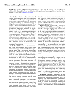
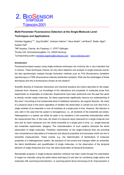
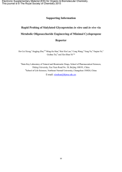
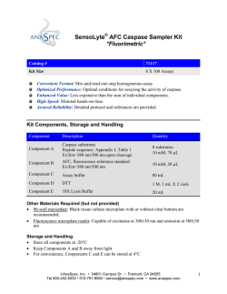
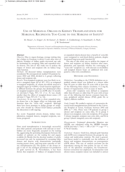
Técnicas avanzadas de
espectroscopia confocal
FRET, FLIM, FRAP, FCS, RICS, …
CIO- León Gto. Octubre 2015
Adán Guerrero
[email protected]
Av Universidad 2001
Universidad Autónoma del Estado de Morelos, 62210 Cuernavaca, Morelos
Fluorescence Resonance Energy Transfer
Motivación
El límite de difracción limita a la microscopía óptica
para resolver estructuras nanoscópicas
•
FRET permite detectar la
interacción entre
moléculas que coinciden
en el espacio.
D
D
A
A
Volumen de detección: 10-15 litros
Volumen de una proteína 81 kDa: 10-12 litros
[5]. R0 was calculated using n = 1.4 andy κ2 = 2/3.
bDansyl-labeled phosphatidylethanolamine.
ENERGY TRANSFER
cEosin-labeled phosphatidylethanolamine.
dThe factor of 1028 between J(λ) in M–1 cm3 and M–1 cm3 (nm)4 arises from 1 nm = 10–7 cm, raised to the fourth power.
aFrom
44
Fluorescence Resonance Energy Transfer
ure the distance from a tryptophan residue to a ligand bindinginsite
ligand
as the
acceptor.
fold change
the when
Förster the
distance.
Thisserves
is because
of the
13.2.1. Orientation Factor κ2
sixth-root dependence
eq. 13.5.
It should also be proteins,
noted
In the incase
of multi-domain
RET has been
A final factor in the analysis of the energy transfer
that the visual impression of overlap is somewhat misleadused to measure conformational changescies
that
move
the factor κ2 which is given by
is the
orientation
ing because the value of J(λ) depends on λ4 (eq. 13.3).
domains
closer or
further
apart. Energy
transfer can also
be en el
FRET
ocurre
una
molécula
donadora
(D)
Comparison
of the entre
spectral
overlap
for
2,5-DPE
and 1,5κ 2 ! and
( cos θ T " 3 cos θ D cos θ A ) 2
DPE suggests
Förster the
distance
for 1,5-DPE,
whereusedatolarger
measure
distance
between
a site on a protein
estado
un aceptor
(A)
en protein
el estado
estacionario
as the excitado
calculated
value y
issurface,
smaller.
The
larger Förster
disa membrane
association
between
subunits,
tance for 2,5-DPE is due to its larger quantum yield.
κ 2 ! ( sin θ D sin θ A cos φ " 2 cos θ D cos θ A ) 2
and
lateral
association
of
membrane-bound
proteins.
In the
Because of the complexity in calculating overlap integrals
case
of macromolecular
reactions
lessθ is the angle between the e
and Förster
distances
it is convenient to association
have several examIn one
these relies
equations
T
ples. Values
of the overlap integral
the
on determination
of a corresponding
precise D–Ato distance,
and more
onthe donor and the transition ab
transition
dipole of
spectra in Figure 13.3 are summarized in Table 13.1.
dipole
of the acceptor,
the simple fact that energy transfer occurs
whenever
the θD and θA are the angles
these dipoles and the vector joining the donor
donors
acceptors
in 8–9
close proximity comparable to
Briefand
History
of Theodorare
Förster
acceptor, and φ is the angle between the planes
the
Förster
distance.
The theory for resonance energy transfer was developed by Professor
Theodor
Förster (Figure
13.4). as
He a proximity indicator
The use
of energy
transfer
was born in Frankfurt, Germany in 1910. He received
illustrates an important characteristic of energy transfer.
a PhD in 1933 for studies of the polarization of reflected Energy
electrons. He
then became
Research
Assistant
in
transfer
canabe
reliably
assumed
to occur whenever
Leipzig, Germany, where he studied light absorption
the donors and acceptors are within the characteristic
of organic compounds until 1942. In this phase of his
Figure 13.1. Fluorescence resonance energy transfer (FRET) for a
Förster
distance,
and
whenever
suitable spectral overlap
work
he applied
the principles
of quantum
mechanics
protein with a single donor (D) and acceptor (A).
to chemistry.
to 1945
he held
occurs. From
The 1942
value
of R
cana Professorbe reliably predicted from the
0
ship in Poznan, Poland. In 1945 he joined the Maxspectral
of theindonors
Planck
Instituteproperties
for Physical Chemistry
Göttingen,and acceptors. Energy
. The rate of energy transfer from a donor to an acceptor where
he wroteishisaclassic
book Fluoreszenz
Organistransfer
through-space
interaction
that is mostly indecher
Verbindungen,
which
has
been
described
as
a
is given
by
T(r)La
transferencia
de energía resulta de "house
interacciones
dipolo–dipolo
pendent
ofthethe
intervening
bible" for
German
community solvent
of spectro-and/or macromolecule.
scopists.
By 1946 Professor
Förster had of
written
In principle,
the orientation
the his
donors and acceptors can
entre D y A.
first
paper
on
energy
transfer,
and
pointed
out
the
1 R0 6
prevent energy transfer between a closely spaced D–A pair,
(13.1) importance of energy transfer in photosynthesis syskT (r ) !
tems.
wasisalso
among
first scien- nonexistent in biomolbutProfessor
such aFörster
result
rare
andthepossibly
τD r
to observe excited-state proton transfer, which is
ecules.
Hence
one can assume
that RET will occur if the
NO involucra la emisión de un fotóntists
(no
radiativa),
la hedistancia
now described
by the Förster cycle. In 1954
discovproperties
are Förster
suitable
and
here τD is the decay time of the donor in the absence of eredspectral
excimer formation.
Professor
died of
a the D–A distance is
r
tiene
que
ser
inferior
a
la
longitud
de
onda
de
la
luz.
attack in his car on the way to work in 1974. For
Figure 13.4.interacProfessor Theodor Förster. 15 May 1910–20 Ma
comparable
to R . A wide variety of biochemical
cceptor, R0 is the Förster distance, and r is the donor-to- heart
additional information see0 [8] and the introduction
Reprinted with permission from [8]. Copyright © 1974, S
tions
result
in inchanges
in distance and are thus
measurable
cceptor distance. Hence, the rate of transfer is equal to the about
Theodor
Förster
[9].
Verlag.
using
RET.
ecay rate of the donor (1/τD)Förster
when theT.D-to-A
distance (r)
Zwischenmolekulare
Energiewanderung
und Fluoreszenz, Ann. Physik 1948, 437, 55
Donador
( )
Aceptor
D emite a longitudes de onda que traslapan
con el espectro de excitación de A
Revisado en: Molecules 2012, 17,4047-40132
protein
withcalculated
a single donor
(D) and acceptor (A).
fer can be
easily
using
444
photons absorbed by the donor which are t
acceptor.
This fraction
is6 given
by
Fluorescence
Resonance
Energy
Transfer
ENERGY TRANSFER
ure the distance from a tryptophan residue to a ligand binding site when the ligand serves as the acceptor.
In the case of multi-domain proteins, RET has been
used to measure conformational changes that move the
domains closer or further apart. Energy transfer can also be
used to measure the distance between a site on a protein and
a membrane surface, association between protein subunits,
and lateral association of membrane-bound proteins. In the
case of macromolecular association reactions one relies less
on determination of a precise D–A distance, and more on
the simple fact that energy transfer occurs whenever the
donors and acceptors are in close proximity comparable to
the Förster distance.
The use of energy transfer as a proximity indicator
illustrates an important characteristic of energy transfer.
Energy transfer can be reliably assumed to occur whenever
the donors and acceptors are within the characteristic
Förster distance, and whenever suitable spectral overlap
occurs. The value of R0 can be reliably predicted from the
spectral properties of the donors and acceptors. Energy
transfer is a through-space interaction that is mostly independent of the intervening solvent and/or macromolecule.
In principle, the orientation of the donors and acceptors can
prevent energy transfer between a closely spaced D–A pair,
but such a result is rare and possibly nonexistent in biomolecules. Hence one can assume that RET will occur if the
spectral properties are suitable and the D–A distance is
comparable to R0. A wide variety of biochemical interactions result in changes in distance and are thus measurable
using RET.
It is important to remember that resonance energy
transfer is a process that does not involve emission and
reabsorption of photons. The theory of energy transfer is
based on the concept of a fluorophore as an oscillating
dipole, which can exchange energy with another dipole
with a similar resonance frequency.4 Hence RET is similar
to the behavior of coupled oscillators, like two swings on a
common supporting beam. In contrast, radiative energy
transfer is due to emission and reabsorption of photons, and
( )
1 R0 from a donor to an acc
Å. The rate of energy transfer
(13.10)
kT (r ) !
kT(r) is
by de transferencia
τ D r de energía de D a A
La given
velocidad
esta dada por:
kT (r )
E
!
6
"1
If the transfer rate is much faster than
decay
rate,
then
R
1 the
0
τ
#
k
(r
)
T
D
kT (r ) If!the transfer rate is slow- (
energy transfer will be efficient.
τD
er than the decay rate, then little transfer will occur during
donde τis
el tiempo
de of
decaimiento
de D en ausencia
D esthe
which
ratio
the
transfer
rate to the
the
excited-state
lifetime,
and
RET
will
be
inefficient.
R0 = 3 nm
la distancia
wheredeτA,D risesthe
decayentre
timeD yofA.the donor in the absen
1.0
of
the
donor
in
the
presence
of
acceptor.
Re
The efficiency
of
energy
transfer
(E)
is
the
fraction
of
R0 es R
la0distancia
de
Förster (tipicamente
en nm).
acceptor,
is
the
Förster
distance,
and
r
is
the
don
D
6,donor
–1(R
photons
absorbed
by
the
which
are
transferred
to
the
0.8
=
τ
/r)
one
can
easily
rearrange
eq.
1
A
D
0
acceptor
distance.
Hence,
the
rate
of
transfer
is
equal
( )
La eficiencia
deistransferencia
de energía (E) es la fracción
acceptor.
This
fraction
given
by
0.6
decayderate
of the
donorpor
(1/τ
the D-to-A
fotones
absorbidos
D que
son transferidos
a A. distan
D) when
0.4
is equal to the Förster distance (R0), and6the transfer
R
k
(r
)
0 donor em
T
0.2
ciency is 50%.EAt
this
distance
(r
=
R
)
the
0
(13.11)
!
E
!
D
"1
6 in the
6 absen
τ
#
k
(r
)
would
be
decreased
to
half
its
intensity
0.0
R0 # r
T
D
0.0
0.5
1.0
1.5
2.0
acceptors.
The rate
of RET
dependsSpectroscopy.
strongly Joseph
on distR
Principles
of Fluorescence
A
r/R0
Lakowicz.
Thirdrate
Editio
which and
is the
of the transfer
rate 13.1).
to the total
decay
is ratio
proportional
to r–6 (eq.
Figure 13.1. Fluorescence resonance energy transfer (FRET) for a
protein with a single donor (D) and acceptor (A).
Å. The rate of energy transfer from a donor to an acceptor
kT(r) is given by
1 R0
kT (r ) !
τD r
E
(r)
6
(13.1)
where τD is the decay time of the donor in the absence of
acceptor, R0 is the Förster distance, and r is the donor-toacceptor distance. Hence, the rate of transfer is equal to the
decay rate of the donor (1/τD) when the D-to-A distance (r)
is equal to the Förster distance (R0), and the transfer efficiency is 50%. At this distance (r = R0) the donor emission
would be decreased to half its intensity in the absence of
acceptors. The rate of RET depends strongly on distance,
and is proportional to r–6 (eq. 13.1).
Förster distances ranging from 20 to 90 Å are convenient for studies of biological macromolecules. These distances are comparable to the size of biomolecules and/or
the distance between sites on multi-subunit proteins. Any
–1. The term κ2 is a factor des
orescence
quenching,
or
cm
g, or
cm–1. The term κ2 is a factor describing the relative ori
her
fluorescence
phenomtion
in
space
of
the
transition
nomtion in space
of thede
transition
dipoles of the donor
Teoría
FRET
2 is usually assumed
e
fluorophore
with
other
acceptor.
κ
2
otherR0 depende
acceptor.
κ is usually
assumedyto
be equal to 2/3, whi
de parámetros
de orientación
espectroscópicos
vent shell.
These nearby
appropriate
for dynamic
random
earby
appropriate
for dynamic
random averaging
of the
dono
Índicetransfer,
de refracción
Rendimiento
cuántico
de Dbelow
or
energy
except
acceptor
(Section
13.2.1,
xcept
acceptor (Section 13.2.1, below). In eq. 13.2 the tra
of
theisdonor
andas a function
rate is written
function
of
roperties
and
rate
written
of r, kTas
(r),a to
emphasiz
ransfer
effective over
dependence on distance.
over isdependence
on distance.
ent intervening
solvent
or integralThe
overlap
integral
or
The
overlap
(J(λ))
expresses
the (J(λ)
degre
n the efficiency
energybetween
spectral
overlap
between
nergy
spectralofoverlap
the donor
emission
andthe
thedon
ac
distance. In
tor absorption:
ce.onInthe D–A
tor absorption:
basic
adia- theory of non-radiaIntegral de traslape
Factor
de
orientación
∞
lications
of RET to∞ biobio∞
4
"0 FD (λ )εA (λ )λ4 dλ
4
cal applications
of
RET
RET
J(λ
! FD (λ
)
ε
(λ
)
λ
dλ
!
(1
J(λ ) ! FD (λ )εA (λ )λ dλ) !
A
∞
F
(λ
)dλ
"
D
0
reviews
(additional
referefer0
0
Principles of Fluorescence Spectroscopy. Joseph R. Lakowicz. Third Edition
nd
areoflisted near
the end of
!
!
D emite a longitudes de onda que traslapan
con el espectro de excitación de A
Revisado en: Molecules 2012, 17,4047-40132
Parejas FRET populares
Revisado en: Molecules 2012, 17,4047-40132
Parejas FRET populares
Tres tipos de sensores FRET
Revisado en: Molecules 2012, 17,4047-40132
Configuraciones posibles de la apolipoproteínaENERGY
A1 TRANSF
454
454
ENERGY TRANSFER
Figure 13.13. Emission spectra of labeled apoA-I in HDL. Revise
from [36].
Figure 13.13. Emission spectra of labeled apoA-I in HDL. Revised
from [36].
tra of labeled apoA-I in discoidal HDL. The spectrum of t
D–A apoA-I
pair shows
a decrease
intensity
tra of labeled
in discoidal
HDL. in
Thedonor
spectrum
of the and
increase
D–A pair
showsinaacceptor
decreaseintensity,
in donorconsistent
intensity with
and about
an 40
transfer.
The presence
of RET
apoA-I
increaseenergy
in acceptor
intensity,
consistent
withproves
aboutthat
40%
in the belt
conformation
13.12)
because
energy transfer.
The
presence of (Figure
RET proves
that
apoA-IRET
is wou
notconformation
occur for the
picket-fence
conformation
where t
in the belt
(Figure
13.12) because
RET would
Figure 13.12. Possible conformations for apolipoprotein apoA-I
donor
are 104D
apart. Otherwhere
groupsthe
agree w
not occur
forand
theacceptor
picket-fence
conformation
when bound
to lipids.
Reprintedforwith
permission from
[36]. Figure
13.12.
Possible
conformations
apolipoprotein
apoA-I
theacceptor
belt Joseph
structure,
butapart.
believe
thegroups
peptides
are with
in a hairp
donor and
are 104D
Other
Principles of Fluorescence Spectroscopy.
R.
Lakowicz.
Thirdagree
Edition
Figure
courtesy
of Dr.
Mary with
G. Sorci-Thomas
from
Wake Forest
when bound
to lipids.
Reprinted
permission from
[36].the
Figure
37
Estudio FRET sobre el plegamiento intracelular de proteínas
PRINCIPLES OF FLUORESCENCE SPECTROSCOPY
ORESCENCE SPECTROSCOPY
455
Figure 13.14.
Schematic neuronales,
of labeled Apo E3 and
Apo E4, and donor
Células
Neuro-2a
(CFP) and RET images in Neuro-2a cells. Reprinted with permission
from [38].
Principles of Fluorescence Spectroscopy. Joseph R. Lakowicz. Third Edition
Indicador FRET para estrógeno
ENERGY TRANSFE
gure 13.21. RET indicator for estrogens using the ligand-binding domain of estrogen receptor. The color scale shows the intensity at 480 nm dividby the intensity at 535 nm. Revised and reprinted with permission from [45]. Copyright © 2004, American Chemical Society.
Principles of Fluorescence Spectroscopy. Joseph R. Lakowicz. Third Edition
Visualización de
la activación de
Rac en células
vivas
Donador: GFP-Rac
Aceptor:
Alexa546-Cinasa
Principles of Fluorescence
Spectroscopy. Joseph R.
Lakowicz. Third Edition
La activación de
Rab13 ocurre en el
extremo de migración
de las células
ublished February 23, 2015
Down
J Cell Biol 2015 208:629-648
yversely,
of
non-RET
donor
quenching
can
addressed
around
the an
donor
in 1979.
RET toformultiple
acc
wavelengths.
Hence
thebe
intensity
measured
atthat
the
transfer
efficiency
quickly
thei
racceptor
will
be larger
thanwith
the the
true
value.
In
suchHence
by it
the
fact
analytical
expression
the donor
complete
labeling
acceptor.
is
essential
to
obtain
complete
labeling
wi
and if
rthe
= transfer
0.5R0 then
the efficiency
is contribuarison
of
efficiencies
observed
from
one,energy
two, and
threeindimensions
is described
in m
F
acceptor
wavelength
typically
contains
some
DA
if
r
is
greater
than
R
.
Because
E
depends
nsfer
efficiency
determined
from
enhanced
sity
for
transfer
two
dimensions
only
appear
0 acceptor,
pletely labeled
with
the
acceptorexp[-σS(t)]
or to
knowdescribes
the extent
of portion
acceptor
labeling.
In
these
equations
that
of
the
57
(13.13)
E
!
1
"
ractical
to
use
RET
to
measure
distances
nching
and
acceptor
sensitization.
See
Problem
in
Chapter
15.
Several
of
these
results
are presen
69
from
the
donor.
sion
is
thought
to
be
the
correct
value.
The
1964,
and
was
extended
to
allow
an
excluded
vo
stance,
measurements
of
the
distance
(r)
F
would
be
larger
than
the
true
value,
D
13
donor
decay
due
to
RET,
σ
is
the
surface
density
of
the
illustrate
the
general
form
of
the
expected
data.
of
r
=
0.5R
to
r
=
2R
.
59
0 acceptor
0 can be addressed
non-RET
donor
quenching
around the donor in 1979. RET to multiple accepto
The use
of
intensities
isR further
complicated
when
r
is
within
a
factor
of
2
of
.
If
r
is
nce
too large.
We are less
concerned
0
acceptor,
and
rc is the distance
of closest
approach
between
Aand
general
description
of described
energy
transfer
o
efficiency
is
typically
measured
using
the
nthe
of need
the transfer
efficiencies
observed
from
one,
two,
three
dimensions
is
in
more
to(r account
for
directly
excitedeffiacceptor emisGr
distance
= 2R0the
) can
then
the
transfer
he
donor
because
protein
moleransfer
efficiency
also
be
calculated
from
the
life2
the
donor
and
acceptors.
The
energy-transfer
efficiency
can
dimensional
surface
has
been
given
by
Fung
an
57in
κ
13.3.3.
Effect
of
on
the
Possible
Range
of
nce
intensity
of
the
donor,
the
absence
ng
and
acceptor
sensitization.
See
Problem
in
Chapter
15.
Several
of
these
results
are
present
he
ERGY
TRANSFER
IN
MEMBRANES
13
n,and
which
is
almost
always
present.
In
the
case
of
and
if these
r do
= 0.5R
then the
efficiency
is
Assuming
no
homotransfer
between
the
donors,
an
in
donors
not
to
the
be
calculated
by
an
equation
analogous
to
eqs.
13.13
and
0contribute
under
respective
conditions
(τ
and
τ
):
Distances
Advanced
T
illustrate
the
general
form
of
the
expected
data.
La
eficiencia
de
FRET
se
mide
usando
la
intensidad
relativa
del
donador
(D),
en
la
ausencia
DA
D
(FDA
) of acceptor:
eled
apoA-I
(Figure
13.13)
the
directly
excited
acceptor
of
amples
oftoresonance
energy
transfer
described
fusion
during
the
donor of
excited-state
lifetime,
the
ractical
use
RET
to
measure
distances
13.14,
except
that
the
intensities
or
lifetimes
are
calculated
ng
the
extent
of
donor
labeling
is
the
A
general
description
energy
transfer
on
a
(FD) y presencia del aceptor (FDA)
ssion
accounted
for
about
halffrom
the
totaldonor
acceptor
emisre
was
a
single
acceptor
attached
to
each
decay
of intensity
the donor
is been
givengiven
by by Fung and bra
integrals
of
the
donor
decay:
of
r
=
0.5R
to
r
=
2R
.
e and donor–acceptor
pair.
dimensional
surface
has
St
0
0
In
distance
measurements
using
RET
there
is
often
co
GY
TRANSFER
MEMBRANES
n.
acceptor
isFbecomes
almost
always
directly
to some
. The
situationIN
more τexcited
complex
forAssuming
DA
DA
for
FRET
en
membranas
no
homotransfer
between
the
donors,
and
n
efficiency
is
typically
measured
using
the
elingEwith
donor
(f
)
is
known
then
2
aE
(13.13)
!
1
"
!
1
"
(13.14)
thewaveeffects of the0 orientation factor κ . At pr
5 In this case the bulk about
donors
and
acceptors.
conent
because
the
acceptor
absorbs
at
the
excitation
Fenergy
es be
ofintensity
resonance
transfer
fusion duringIDthe
excited-state
lifetime, the
(t ) donor
!
I(tD)exp("t/τ
) # inte
ete
τdescribed
D donor,
I
D ) exp""σS(t
nce
the
in the
an
used
to of
calculate
the transfer
D absence
1
D
2
there
isEno!
way
to measuredtκ , except by
determinati
ofaused
acceptors
is important
because
thedonor
acceptor
gth
to acceptor
excite
the
donor,
resulting
in
acceptor
emis1
"
(13.28)
as
single
attached
to
each
decay
of
the
donor
is
given
by
13
no
0
q.(F13.14
becomes
etion
)
of
acceptor:
τ
I
DA
D
determines
the D–A
proximity.
Also,
onex-raywhere
the
crystal structure,
D or NMR structure, in which
nimportant
without
RET.
eency
situation
becomes
more
complex
for
can also
be
calculatedthe
from
the life- donde
and
to
remember
assumptions
involved
in
Efectos
de
marcaje
incompleto
onsider
the
presence
of
more
than
a
single
accepthe distance
would be
known and thus there would
5 Inthe
rsrespective
and acceptors.
this
case
the
bulk
conCalculation
of
transfer
efficiency
from
the
0
conditions
(τDA
and 13.13
τDUse
): RET
(1
ID (t )only
! is
ID moderately
exp("t/τ D ) complex
exp""σS(tand
)#
reg
of
eqs.
13.26–13.28
Equations
and
13.14
are
dacceptors
each
In
spite
of
the
complexity,
has
1these
# fAdonor.
)equations.
F
F
1 requires
reason
to use energy∞ transfer. However, it is possible
DADAbecause
is important
the acceptor
ancedEacceptor
emission
careful
consideration
(13.17)
!donor-acceptor
1#
(13.13)
!
1for
"
ide
requires
use
of
numerical
integration.
However,
the
ble
potential
studies
of
lateral
organization
in
2
cable
to
pairs
that
are
separated
by
a
6
determines
the
D–A
proximity.
Also,
one
limits
on donor
κ that
setexp""(t/τ
limits on
the range of po
FDFintensities.
S(t ) in
! turn
{1 "
A
D fA
all
the
interrelated
Assuming
that
the
D ) (R0 /r ) # } 2πr dr
where
es. For
example,ofτconsider
a membrane
thatisconapproach
quite general, and can be applied to a wide varibo
DA
der
the presence
more than
a single
accep-
Recapitulando y mensajes para llevar a
casa sobre la implementación de FRET
!
(
)
!
D–A
distances.
These
limits are determined from
athesituation
frequently
encountered
for
r
s distance,
not Eemit
acceptor wavelength,
the
efficiency
of
! 1at"
(13.14)
etyRET
of circumstances
by using different expressions for S(t)
h
donor.
In
spite
of
the
complexity,
has
τ
anisotropies
of the
donor and acceptor, which reflec
∞
T
donor
quenching,
(FDA
/F
<<
1),the
Efectos
deby
sangrado
espectral
iency
also
be Dcalculated
from
lifeed
proteins.
However,
a Dsingle
fixed
donor–acceptor
sfer
iscan
given
that correspond
to different geometric conditions. Figure
gra
otential
for
studies
of
lateral
organization
in
6 the dynamic
(excitación
directa
del
aceptor)
extentand
of S(t
orientational
averaging
toward
unlabeled
acceptor
can
result
in
a
respective
conditions
(τmixture
and
τ
):
(1
)
!
{
1
"
exp""(t/τ
)
(R
/r
)
# } 2πrin
dr
nce
is
not
found
for
a
of
donors
acceptors
D
0
DA
D
13.28
shows
the
calculated
transfer
efficiencies
for
a
case
FRET
en
solución….
lip
orremember
example, consider
a membraneinvolved
that con- in
the
assumptions
2 = 2/3.
age
of
κ
r
ex
em
ution,
nor
for
donors
and
acceptors
dispersed
randomwhich
the
donor
to
acceptors
are constrained to the
tra
ε
(λ
)
F
(λ
)
1
A
AD
D
A
ions.EEquations
13.13 and 13.14
are only The(13.25)
2 has been discussed in detail by
problem
of
κ
!
"
1
interface region of a bilayer. Several features of
lab
exτ DA
em lipid–water
f
ε
(λ
)
F
(λ
)
Dand
or-acceptor
by
a coworkers10–12 and summarized by Cheung.13 The
E ! 1D pairs
"D thatA areA separated
(13.14)
these predicted data are worthy of mention. The efficiency
com
τ
D
a situation frequently encountered
for
is thatwith
the Rdonor
andefficiency
acceptor of
move
freely wit
of transferidea
increases
and the
energy
aci
c
[
]( )
ex
ex
!
c
0
Fluorescence Lifetime Imaging Microscopy
NCIPLES OF FLUORESCENCE SPECTROSCOPY
e-domain and frequency-domain measurements are in
espread use.
1. Meaning of the Lifetime or Decay Time
or to further discussion of lifetime measurements, it is
ortant to have an understanding of the meaning of the
ime τ. Suppose a sample containing the fluorophore is
ted with an infinitely sharp (δ-function) pulse of light.
s results in an initial population (n0) of fluorophores in
excited state. The excited-state population decays with
te Γ + knr according to
dn(t )
! (Γ " knr ) n(t )
dt
The denominator is equal to τ
parts, one finds the numerator
single exponential decay the a
remains in the excited state is e
<t> !
It is important to note that
complex decay laws, such as
decays. Using an assumed dec
can always be calculated using
age lifetime can be a complex
describing the actual intensity
n(t)(4.1)
= n0 exp(–t/τD).
this reason, caution is necessary
lifetime.
the instrument
to a zero lifetime
sample.
This curve
typmethods.
In time-domain
or pulse
fluorometry,
the is
sample
that
sources. The TAC has to be reset and set to zero before each
collected
using of
a light
dilute(Figure
scattering
such
isically
excited
with a pulse
4.1).solution
The width
of as
the
start pulse, which takes a finite amount of time. The TAC
es be
colloidal
silica
(Ludox)
and
no
emission
filter.
This
decay
pulse is made as short as possible, and is preferably much
can be constantly in reset mode if the start signals arrive too
of th
represents
the
shortest
time
profile
that
can
be
measured
by
shorter than the decayTIME-DOMAIN
time τ of the sample.
The timerapidly. The emission signals occur about 1 per 100 excitaa mi
4
LIFETIME
MEASUREM
dependent intensity is measured following the excitation
tion pulses, and thus much less frequently than the excitathe d
tion pulses. These emission pulses are used to start the TAC,
pulse,
andthat
the decay
is calculatedwhen
from the
slopefluoropho
of
effec
form
wouldtime
beτ observed
many
and the next laser pulse is used to stop the TAC.
a plot of log I(t) versus t, or from the time at which the
late
excited
and
numerous
photons
are
observed.
Howev
There are many subtleties in TCSPC that are not obviintensity decreases to 1/e of the intensity at t = 0. The intenthe
TCSPC
the
conditions
are adjusted
that less tha
ous at first examination. Why is the photon counting rate
sity
decays are
often
measured through
a polarizersooriented
limited to 1 photon per 100 laser pulses? Present electronphoton is detected per laser pulse. In fact, the detecti
ics for TCSPC only allow detection of the first arriving phois typically 1 photon per 100 excitation pulses. The
ton. The dead times range from 10 microseconds in older
measured between the excitation pulse and the ob
systems to about 120 ns with modern TCSPC electronics.
photon and stored in a histogram. The x-axis is the tim
These times are much longer than the fluorescence
decay. The dead time in the electronics prevents
ference and the y-axis the number of photons detec
detection of another photon resulting from the same excithis time difference. When much less than 1 pho
tation pulse. Recall that emission is a random event. Foldetected per excitation pulse, the histogram represe
lowing the excitation pulse, more photons are emitted at
early times than at late times. If all these photons could be
waveform of the decay. If the count rate is higher t
measured, then the histogram of arrival times would repretogram is biased to shorter times. This is becaus
sent the intensity decay. However, if many arrive, and only
TCSPC only the first photon can be observed. At p
the first is counted, then the intensity decay is distorted
the electronics are not fast enough to measure multip
to shorter times. This effect is described in more detail in
Section 4.5.6.
tons per pulse when the lifetimes are in the nano
Another important feature of TCSPC is the use of the
Fig
range.
Multiple
photons
per
pulse
can
be
measur
rising edge of the photoelectron pulse for timing. This
me
Figure
4.1. Pulse
or time-domain
lifetime measurements.
decay
times
near
a microsecond
or longer. Specialize
sio
allows phototubes with ns pulse widths to provide subnanosecond resolution. This is possible because the rising
tronics are used for measuring the time delay betwe
edge of the
single-photon
pulses in
is the
usually
steeper
than
one
Figure 4.7. Principle
of TCSPC.
The pulses
middle
panel
repexcitation and emission (Figure 4.8). The experimen
Figure 4.9. TCSPC data for 2,5-diphenyl-1,3,4-oxadiazole (PPD) in
would
expect
from thefraction
time response
of the PMT.
Also,
the
esent the output
from
a constant
discriminator
(see
Figure
TCSPC data for 2,5-diphenyl-1,3,4-oxadiazole
(PPD)
incavity
ethanol.
The
with
the
excitation
pulse
that
excites
the
samples
and
ethanol.
The
light
source
was
an
R6G
dye
laser,
dumped
at 1
of a[11].
constant fraction discriminator provides improved
4.22). Reviseduse
from
light source was anMHz.
laser,
dumped
at 1 MHz.
The dye
detector
was ancavity
R2809 MCP
PMT (Hamamatsu).
TheThe
left
time resolution by removing the variability due to the
asideR6G
signal
to
the
electronics.
This
signal
is
passed thr
of the residuals (lower panel) show some minor systematic error.
detector
was an R2809 MCP PMT (Hamamatsu).
amplitude of each pulse.
From
[15].
constant function discriminator (CFD), which acc
The lifetime is the average amount of time a fluorophore
remains in the excited state following excitation.
Principles of Fluorescence Spectroscopy. Joseph R. Lakowicz. Third Edition
of
is called demodulation,
also beinused
to calcuChapter
5, but it is valuable to understand the basi
usualeffect
expression
for a singleand candetail
he
late the decay time. FD measurements
typicallyrelating
use both lifetimes to phase and modulation. Th
equations
nthe phase and modulation information. At present, both
modulation of the excitation is given by b/a, where a is th
ed
Phase-modulation or frequency-domain lifetime
measurements.
average intensity and b is the peak-to-peak height
(4.2)
exp (#t / τ )
time 0. The lifetime τ is the
e, τ = (Γ + knr)–1. In general, the
sum of the rates which depopfluorescence lifetime can be
a plot of log I(t) versus t (Figy by fitting the data to assumed
of th
incident light (Figure 4.2). The modulation of the emissio
The modulation of the excitation
is defined similarly, B/A, except using the intensities of th
is given by b/a, where a is the
emission (Figure 4.2). The modulation of the emission
average intensity and b is the
measured relative to the
excitation, height
m = (B/A)/(b/a).
Whil
peak-to-peak
of the
m is actually a demodulation
incidentfactor,
light. it is usually called th
modulation. The other experimental
observable
is the phas
The modulation
of the emission
delay, called the phase is
angle
(φ),similarly,
which is B/A,
usually
measure
defined
except
from the zero-crossing using
timesthe
of the
modulated
intensities
of thecomponent
modulation
of the
The phase angle (φ) emission.
and theThe
modulation
(m)
can b
emission
is measured
relative to
employed to calculate the
lifetime
using
erage amount of time a fluoted state following excitation.
the excitation, m = (B/A)/(b/a).
ating the average time in the
is obtained
t over
Figureby
4.2. averaging
Phase-modulation
or frequency-domain lifetime measure#1
(4.5
tan
φ
!
ωτ
,
τ
!
ω
tan φ
φ
φ
ments.
The ratios
B/A (φ)
and b/a
represent
the modulation of the emisThe
phase
angle
and
the
orophore:
sion and excitation, respectively.
modulation
(m) can be employed to
calculate the lifetime using
∞
!0 t exp (#t / τ ) dt
1
1 1
1/2
(4.3)
! ∞
m!
(4.6
,
τ
!
#
1
m
2
ω m
!0 exp (#t / τ )dt
√1 " ω2τ 2m
[
]
Principles of Fluorescence Spectroscopy. Joseph R. Lakowicz. Third Edition
Comparison of time-domain (left) and frequency-domain (right)
decay time measurements of N-acetyl-L-tryptophanamide
(NATA).
TIME-DOMAIN LIFETIME MEASUR
3. Comparison of time-domain
(left) andoffrequency-domain
decay time measurements
N-acetyl-L-tryptophanamide
Principles
Fluorescence(right)
Spectroscopy.
Joseph R.ofLakowicz.
Third Edition (NA
detector phase angles can be fit to determine the
gle and modulation of the emission. Since the
nsitive intensities were measured using an imaging
the data can be used to create an image when the
or color is based on phase angle, modulation or
4
lifetime.
The data in Figure 22.5 can be used to create a calibration curve for calcium (Figure 22.6). These curves can be
used to determine the concentration of calcium from the
phase or modulation of the emission. It is important to rec-
Fluorescence Lifetime Imaging Microscopy
FLUORESCENCE-LIFETIME IMAGING MICROSCOPY
FETIME IMAGING OF CALCIUM
QUIN-2
Determination of Calcium Concentration
etime
imaging depends on the use of a probe that
lifetime in response to a change in conditions.
of calcium concentrations requires a probe that
calcium-dependent lifetimes. Figure 22.5 shows
ging frequency-domain data for the calcium probe
with various concentrations of calcium.6 The freesponse shifts dramatically to lower frequencies at
Figure 22.3. Schematic of lifetime imaging using phase-sensitive
images.
2.1.1. FLIM Using Known Fluorophores
Figure 22.5. Frequency-domain intensity decays for Quin-2 with
varying concentrations of calcium. The data were fit globally with two
lifetimes τ1 = 1.38 ns and τ2 = 11.58 ns.
Figure 22.4. Phase-sensitive intensities of standard fluorophores at
various detector phase angles. The decay times from left to right
are 0.04 ("), 1.10 (∆), 3.75 (!), and 9.90 ns (!). The modulation frequency was 49.53 MHz. DMSS, 4-dimethylamino-ω-methylsulfonyltrans-styrene; 9-CA, 9-cyanoanthracene; POPOP, p-bis[2-(5-phenyloxazazolyl)]benzene. θ1 is the arbitrary phase angle of the incident
light.
Principles of Fluorescence Spectroscopy. Joseph R. Lakowicz. Third Edition
Fluorescence Lifetime Imaging Microscopy
PRINCIPLES OF FLUORESCENCE SPECTROSCOPY
e and modulation of Quinom [7].
ons can be determined
ulation frequency withnential decay. This is
ase angle and modulathe complexity of the
ration curve would be
frequencies.
Figure 22.6. Dependence of the phase angle and modulation of Quin2 on the calcium concentration. Revised from [7].
Cells
calcium concentrations can be determined
theognize
phase that
and the
modulausing measurements
calcium
concentrationsat a single modulation frequency withof the multi-exponential decay. This is
gesout
for resolution
Quin-2 in three
because there is always a single phase angle and modulaThe intensity of Quin-2
tion of the emission irrespective of the complexity of the
s of the cells (top). The
decay. Of course, a different calibration curve would be
e if the intensity differobtained using different modulation frequencies.
n-2 concentrations or to
Phase-sensitive images
22.2.2.
Lifetime
Images of Cos Cells
hown
in Figure
22.2 and
Principles of Fluorescence Spectroscopy. Joseph R. Lakowicz. Third Edition
7
Protein Kinase C Activation
Wide-field frequency-domain FLIM can be used to study
the activation of intracellular proteins. One example is the
central cell decreases because of energy tran
3.5-labeled antibody. These images are not co
difficult to know if phosphorylated PKC appe
throughout the cell or is localized near the m
Activation of lipid/calcium-dependent protein
kinase C (PKC) in Cos7 cells
GFP-tagged PKC.
GFP-lifetime images
the central cell was
injected with Cy3.5IgG specific for the
phosphorylated epitope
of PKC.
All the cells were treated with phorbol myristoyl acetate (PMA).
Figure 22.8. Activation of lipid/calcium-dependent protein kinase C (PKC) in Cos7 cells. The top panels show the intensity images
Principles
Fluorescence
Spectroscopy.
Joseph
R.show
Lakowicz.
Third
Edition
PKC. All
the cells were of
treated
with phorbol myristoyl
acetate (PMA). The
lower panels
the GFP-lifetime
images
the central c
Figure 22.17. pH-dependent phase and modulation values of BCECF
for 820 nm excitation with a Ti:sapphire laser, 80 MHz. Revised from
[57].
image shows that BCECF is present in the
interstitial spaces. The modulation is higher
is lower in the interstitial spaces. These data
be imaged within and around the keratinoc
shows the ability of FLIM to provide quan
lar imaging using minimal perturbation of
Registros de pH en células epiteliales de cornea
a una profundidad def 6.8 micras usando BCECF
PRINCIPLES OF FLUORESCENCE SPECTROSCOPY
751
except that the phase and modulation of the emission is
measured rather than using TCSPC. An example of such
measurements is lifetime imaging of the stratum corneum,
which is the outermost layer of the skin. The lifetime probe
was BCECF,57 which displays a pH-dependent change in
lifetime. This change was used to obtain a calibration curve
of phase and modulation versus pH (Figure 22.17). The
stratum corneum was imaged using two-photon excitation
of BCECF at 820 nm. It was possible to obtain images at
various depths in the stratum corneum because the long
wavelength used for two-photon excitation can penetrate
tissues and two-photon excitation is intrinsically confocal
due to localized excitation at the focal point of the laser.
The images of BCECF at a depth of 6.8 microns in the stratum corneum are shown in Figure 22.18. The intensity
image shows that BCECF is present in the cells and in the
interstitial spaces. The modulation is higher and the lifetime
is lower in the interstitial spaces. These data allow the pH to
Figure
22.18.ofpH
lifetime imaging of the skin stratum corneum at a depth of 6.8 microns using BCECF. See Figure 22.17. η is refr
Figure 22.17. pH-dependent phase and modulation
values
BCECF
environment.
withimaged
permission from
[57]. Images
courtesy of the
Dr. Kerry
M. Hanson from the
University
of
within
and around
keratinocytes.
This
result
for 820 nm excitation with a Ti:sapphire laser, 80surrounding
MHz. Revised
from Reprintedbe
Champaign.
[57].
shows the ability of FLIM to provide quantitative molecular imaging using
minimal
perturbationThird
of tissues.
Principles of Fluorescence Spectroscopy.
Joseph
R. Lakowicz.
Edition
Medidas FLIM-FRET multifotónicas en células HeLa
co-expresando EGFP y mCherry.
Revisado en: Molecules 2012, 17,4047-40132
Fenómeno de transporte que ocurre en la
naturaleza
Generalización del
concepto de difusión
Traslacional
Rotacional
Anómala
(fluorescence recovery
eaching)
Métodos que permiten cuantificar la difusión
uctuations
nd dynamic ICS
❖
Basados en una perturbación
❖
FRAP
tal difference between
Basados en fluctuaciones
although they are
FCS, ICS,RICS
sical phenomena they
❖
❖
http://www.lfd.uci.edu/workshop/2013/
Schematic representation of a FRAP and iFRAP experiment.
(A) A region of interest (ROI) is selected, bleached with an intense laser beam, and the fluorescence recovery in the ROI is measured
over time. (B) In iFRAP, the reverse is done and a ROI is selected to remain intact, while the rest of the cell is bleached. This is
particularly useful when studying dynamic movement in organelles such as the nucleus.
Revisado en: Molecules 2012, 17,4047-40132
Example of a FRAP experiment to show that
monomeric GFP can pass the nuclear membrane.
A) Myoblast cell line (myo3) homogenously expressing GFP-Myosin III before bleaching. (B) A region of interest (ROI) is bleached
with high intensity laser light. Directly after bleaching, the cell shows a dark area in which the fluorochromes were permanently
damaged and thus no longer emit light (C). The fluorescence in the photobleached region recovers via replacement with intact
fluorochrome molecules from the surrounding area (D). Note that the total amount of fluorescence has decreased during the
experiment, because a substantial amount of fluorochromes were irreversibly damage.
Revisado en: Molecules 2012, 17,4047-40132
Anatomy of a typical FRAP curve
(A) From the initial (pre-bleach) fluorescence intensity (Ii), the signal drops to a particular low value (I0) as the high intensity laser
beam bleaches fluorochromes in the ROI. Over time the signal recovers from the post-bleach intensity (I0) to a maximal plateau
value (I∞). From this plot and equations 11–12, the mobile fraction (Mf), immobile fraction (IMf), I½ and corresponding time (τ½ –
the time for the exchange of half the mobile fraction between bleached and unbleached areas) can be calculated (Light blue line:
reference photobleaching curve to correct for fluorescence loss during data acquisition). The information from the recovery curve
(from I0 to I∞) can be used to determine the diffusion
constant and the
binding
dynamics of fluorescently
labeled proteins.
Revisado
en:
Molecules
2012, 17,4047-40132
Anatomy of a typical FRAP curve
Based on different recovery profiles, the protein mobility can be classified as (B) highly mobile with virtually no immobile fraction,
(C) intermediate mobile with an immobile fraction, or (D) immobile.
Revisado en: Molecules 2012, 17,4047-40132
Simultaneous FRAP and FRET measurements to separately
determine the mobility of interacting and noninteracting
CFP- and YFP-tagged proteins in a single cell nucleus.
(A) Schematic representation of the method. A 100 ms high-intensity bleach pulse at 514 nm is applied
to irreversibly photobleach YFPs in a narrow strip spanning the nucleus. Redistribution of YFP and CFP
fluorescence is recorded at 100 ms intervals at 458 nm. Donor (CFP) emission (increased because of
unquenching as a result of acceptor [YFP] bleaching) represents the mobility of interacting molecules
only (donor-FRAP). Acceptor emission represents the total pool of YFP-tagged molecules irrespective of
interaction (acceptor-FRAP).
Revisado en: Molecules 2012, 17,4047-40132
Simultaneous FRAP and FRET measurements to separately
determine the mobility of interacting and noninteracting
CFP- and YFP-tagged proteins in a single cell nucleus.
(B) Graph showing CFP and YFP fluorescence intensities in the bleached strip plotted against time.
Experiments were performed in Hep3B cells expressing CFP-YFP fusions (red line indicates CFP
fluorescence [donor-FRAP], and blue line indicates YFP fluorescence [acceptor-FRAP]), or in Hep3B
cells expressing separate CFPs and YFPs (yellow line indicates CFP, and green line indicates YFP; n =
30). (C) Inverted donor-FRAP (red line) and acceptor-FRAP (blue line) plotted against time, showing
similar kinetics. The curves were normalized by calculating Inorm = (Iraw − I0)/(Ifinal − I0), where I0 and
Ifinal are the fluorescence intensities immediately after the bleach and after complete recovery,
Revisado en: Molecules 2012, 17,4047-40132
respectively.
(fluorescence recovery
eaching)
Métodos que permiten cuantificar la difusión
uctuations
nd dynamic ICS
❖
Basados en una perturbación
❖
FRAP
tal difference between
Basados en fluctuaciones
although they are
FCS, ICS,RICS
sical phenomena they
❖
❖
http://www.lfd.uci.edu/workshop/2013/
Fluctuaciones coaccionadas por el movimiento de las partículas
Se requiere un volumen de observación reducido
❖
Parámetros registrados:
❖
Velocidad de movimento.
❖
Concentración de partículas.
❖
Cambios en la intensidad de la
fluorescencia durante el proceso re
observación, por ejemplo cambios
de forma.
Note que el espectro de las fluctuaciones creadas por el movimiento de las partículas
es “plano”mientras que el espectro fluctuaciones en la fluorescencia no lo es.
http://www.lfd.uci.edu/workshop/2013/
Análisis espectroscópico de moléculas fluorescentes
https://www.dkfz.de/Macromol/research/fcs.html
Factores que determinan la intensidad de la señal de
fluorescencia
What determines the
intensity of the fluorescence
signal??
This is the fundamental equation in FCS
F t
kQ = quantum yield and detector
sensitivity (how bright is our
probe). This term could contain
the fluctuation of the
fluorescence intensity due to
internal processes
Q d W
C
W(r) describes the
profile of illumination
t
C(r,t) is a function of the
fluorophore concentration
over time. This is the term
that contains the “physics”
of the diffusion processes
The value of F(t) depends on the profile of illumination!
http://www.lfd.uci.edu/workshop/2013/
La definición de la función de autocorrelación
The definition of the Autocorrelation Function
F t
F t
G
Photon Counts
F t
F t F t
F t
time
Average Fluorescence
t
t+
http://www.lfd.uci.edu/workshop/2013/
La función deTheauto
correlación
Autocorrelation
Function
G(0)
1/N
As time (tau) approaches 0
Diffusion
In the simplest case, two parameters define the autocorrelation funct
http://www.lfd.uci.edu/workshop/2013/
El efectoThe
de la
concentración
de las moléculas
en la curva de
Effects
of Particle Concentration
on the
autocorrelación
Autocorrelation
Curve
Observation volume
<N> = 2
<N> = 4
http://www.lfd.uci.edu/workshop/2013/
El efecto delThe
tamaño
las partículas
en la curva de
Effectsde
of Particle
Size on the
autocorrelación
Autocorrelation
Curve
Diffusion Constants
300 um2/s
90 um2/s
71 um2/s
Slow Diffusion
Fast Diffusion
Stokes Einstein Equation:
D
k T
r
and
MW
Volume
r
Monomer > Dimer
Only a change in D by a factor of 21/3, or 1.26
http://www.lfd.uci.edu/workshop/2013/
Recapitulando
http://www.picoquant.com/applications/category/life-science/fluorescence-correlation-spectroscopy-fcs
Correlación entre
dos
canales
de
fluorescencia
Two Channel Cross correlation
lfd
The cross correlation
ONLY if particles are observed in both channels
Red filter
Each detector observes
particles with a particular color
The cross correlation signal:
Only the green red molecules are observed!!
http://www.lfd.uci.edu/workshop/2013/
Sample
Green filter
La función
de
correlación
cruzada
Calculating the Cross correlation Function
lfd
Detector 1: Fi
time
t+t
t
Gij
dFi t dF j t
Fi t
Fj t
Detector 2: Fj
time
http://www.lfd.uci.edu/workshop/2013/
Parámetros
celulares
que
se
pueden
cuantificar
con
FCS
y
FCCS
PERSPECTIVE
a
Size
Viscosity, hindered diffusion,
membrane phase
b
Directed transport
Membrane binding
Stoichiometry
G
Affinity
Oligomerization
Bacia K, Kim SA,
Schwille Pby
(2006)
cross-correlation
spectroscopy
in living cells. Nat Methods
3: 83–89
igure 1 | Parameters
assessed
FCSFluorescence
and FCCS.
(a) Applications
of fluorescence
autocorrelation
(top) and c
Espectroscopía de correlación de la fluorescencia por barrido
espacial
Fluctuation analysis: single point and scanning
Single point FCS
Time
0
Correlation
1
1.0
1.0
2
4
8
0.9
0.6
0.3
RICS
Single point FCS
Scanning FCS and RICS
Shift (pixel)
0
Correlation 1.00
1
1.00
http://www.lfd.uci.edu/workshop/2013/
2
0.66
4
8
0.14
0.00
Escaneo por entramado
(RICS: Raster
Image Correlation
Spectroscopy)
Raster
Scanning
lfd
http://www.lfd.uci.edu/workshop/2013/
En RICS lainformation
información temporal
mediante el
Temporal
hiddenesinobtenida
the raster-scan
espacial
image: escaneo
the RICS
approach
lfd
http://www.lfd.uci.edu/workshop/2013/
Relación entre el tiempo y el espacio en RICS
lfd
Prt
The RICS approach for diffusion
G RICS
S
Dt
r
Dt
http://www.lfd.uci.edu/workshop/2013/
G
http://www.lfd.uci.edu/workshop/2013/
Autocorrelation Adenylate Kinase
EGFP
Diffusion constants (um2/s) of AK
EGFP in the cell (HeLa).
At the membrane, a dual diffusion rate is calculated from FCS data. Away from the
plasma membrane, single diffusion constants are found.
http://www.lfd.uci.edu/workshop/2013/
Mapeo de las constantes de difusión de paxilina-EGFP
http://www.lfd.uci.edu/workshop/2013/
Conclusions
lfd
Techniques
FCS
Temporal-ICM
RICS
Line-RICS
RICS
Time Res.
Spatial Res.
Correlación
temporal
sec
m
(Escaneo
por <0.5
línea)
Used to Study
Protein aggregates
Transmembrane proteins
Soluble proteins
~2 m
Correlación
temporal
Binding interactions
en
imágenes
(detectores
CCD)
msec
Soluble proteins
<0.5 m
sec-msec
Binding interactions
Resolución temporal
de cada técnica
http://www.lfd.uci.edu/workshop/2013/
¡Gracias!
FRET, FLIM, FRAP, FCS, RICS, …
CIO- León Gto. Octubre 2015
Adán Guerrero
[email protected]
Biot ecnología
EN MOVIMIENT
REVISTA DE DIVULGACIÓN DEL INSTITUTO DE BIOTECNOLOGÍA DE LA UNAM
Biotecnología en Movimiento
Revista de Divulgación del
Instituto de Biotecnología
de la UNAM
Ejemplar número: 2, julioagosto-septiembre de 2015
UN MODELO EXPERIMENTAL
para estudiar la obesidad
EL ÁCIDO FÓLICO
y las plantas
EMPRENDER
con compuestos que pican
LA DESAPARICIÓN
de las abejas 2da. parte
LA ECONOMÍA en el
SIGLO XXI
LAS NUEVAS TECNOLOGÍAS
y los patógenos
DEL PULQUE Y LA SEQUÍA
en las plantas
LOS INICIOS
del IBt 2da. parte
Unidad de Secuenciación
Masiva y Bioinformática
Disponible en: www.ibt.unam.mx
NUMERO 2
JULIO-AGOSTO-SEPTIEMBRE DE 2015
www.ibt.unam.mx
Principles of
Fluorescence Spectroscopy
Joseph R. Lakowicz
Third Edition
•
Fluorescence Resonance Energy Transfer
•
•
•
•
Fluorescence Lifetime Imaging Microscopy
•
•
•
•
•
Ch. 13. EnergyTransfer
Ch. 14. Time-Resolved Energy Transfer and Conformational Distributions of
Biopolymers
Ch. 15. Energy Transfer to Multiple Acceptors in One,Two, or Three Dimensions
Ch. 4. Time-Domain Lifetime Measurements
Ch. 5. Frequency-Domain Lifetime Measurements
Ch. 22. Fluorescence-Lifetime Imaging Microscopy
Fluorescence Recovery After Photobleaching
Fluorescence Correlation Spectroscopy / Raster Image Correlation
Spectroscopy
•
Ch. 24. Fluorescence Correlation Spectroscopy
Molecules 2012, 17, 4047-4132; doi:10.3390/molecules17044047
OPEN ACCESS
molecules
ISSN 1420-3049
www.mdpi.com/journal/molecules
Review
Advanced Fluorescence Microscopy Techniques—FRAP, FLIP,
FLAP, FRET and FLIM
Hellen C. Ishikawa-Ankerhold 1,†,*, Richard Ankerhold 2 and Gregor P. C. Drummen 3,†,*
1
Ludwig Maximilian University of Munich, Institute of Anatomy and Cell Biology, Schillerstr. 42,
Abstract:
80336 München, Germany
2
Carl
Zeiss Microimaging
GmbH,
Kistlerhofstr.recovery
75, 81379after
München,
Germany (FRAP), the related
…The
techniques
described here
are fluorescence
photobleaching
3
fluorescence
loss in photobleaching
localization
photobleaching
Bionanoscience
and Bio-Imaging (FLIP),
Program,fluorescence
Cellular Stress
and Ageingafter
Program,
Bio&Nano(FLAP),
Förster
or fluorescence
resonance
energy
transfer (FRET) and the different ways how to
Solutions,
Helmutstr.
3A, 40472
Düsseldorf,
Germany
measure FRET, such as acceptor bleaching, sensitized emission, polarization anisotropy, and
†
fluorescence
lifetime
imagingequally
microscopy
These authors
contributed
to this(FLIM).
work.
First, a brief introduction into the mechanisms underlying fluorescence as a physical phenomenon and
* Authors to
whom correspondence
should
be addressed;
fluorescence,
confocal,
and multiphoton
microscopy
is given.
E-Mail: [email protected] (H.C.I.-A.);
Subsequently, these advanced microscopy techniques are introduced in more detail, with a practical
[email protected]
(G.P.C.D.);
advantages
they can bring to cell biological
research.Tel.:+49-89-218075-873 (H.C.I.-A.);
Fax: +49-89-218075-004 (H.C.I.-A.); Tel.: +49-211-2297-3648 (G.P.C.D.);
Fax: +49-3222-240-7500 (G.P.C.D.).


© Copyright 2026