
CRATERS MADE BY SEVERELY FRAGMENTED ASTEROIDS
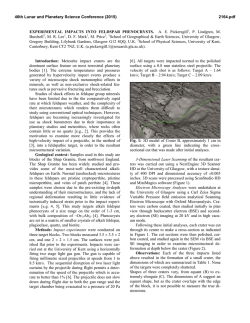
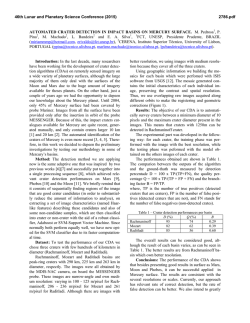
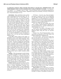
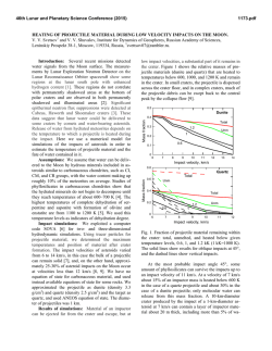
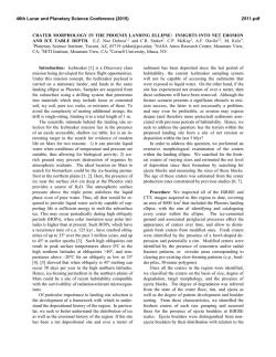
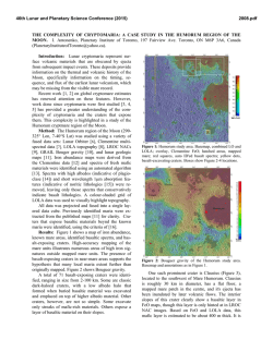
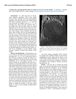
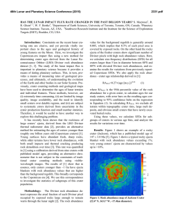
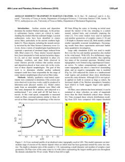
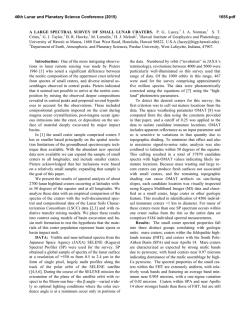
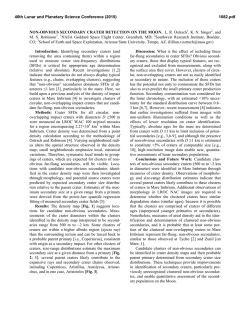
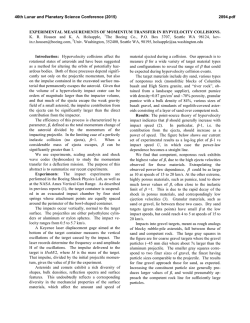
46th Lunar and Planetary Science Conference (2015)
1442.pdf
CRATERS MADE BY SEVERELY FRAGMENTED ASTEROIDS. V. V. Shuvalov1 and N. A. Artemieva1,2,
1
Institute for Dynamics of Geopsheres, Russian Academy of Science, [email protected]; 2Planetary Science
Institute, Tucson, [email protected].
Introduction: Small asteroids (10 - 300 m in diameter), although strongly fragmented in Earth’s atmosphere, are able to reach the surface with high
enough velocity to form an impact crater or a crater
strewn field. The latter scenario, typical for iron asteroids < 50 m, is well-known from observations
(Sikhote-Aline, Campo del Cielo, Henbury strewn
fields, [1-3]) and relatively well-understood [4-5].
However, many other small terrestrial craters could be
formed by severely fragmented in atmosphere stony
asteroids. In this paper we use numerical modeling to
figure out how fragmentation may influence the crater
shape, ejecta distribution, and projectile survivability.
Methods and initial conditions: We use the
2D/3D hydrocode SOVA [5] complemented by the
ANEOS equation of state for non-porous quartzite
[6,7]. The code takes into account the influence of dry
friction (K=0.65) on the motion of disrupted rocks [8].
A fragmented asteroid is represented by three simplified (to use axial symmetry as much as possible) ways:
1) as an oblate spheroid with various aspect ratios A
(from 1 to 512) to mimic the projectile lateral expansion after its fragmentation in atmosphere [10-11]; 2)
as a system of tori (a cloud of fragments); 3) by 4, 6,
and 8 fragments of the same size dispersed to various
distances. In all cases the total mass is equal to the
mass of a 100-m-diameter stony asteroid, an impact
velocity is 18 km/s, and an impact angle is 90°.
Fig.1. Craters produced
by oblate spheroids.
The darkest curve corresponds
to
A=1
(sphere), the lightest
gray to A= 512).
Results. Craters formed by oblate projectiles:
Fig.1 shows the final crater shape for various aspect
ratios A. Obviously, with increasing flattening of the
projectile, the crater becomes smaller and shallower.
Whereas the gravity-scaled size π2 is the same in all
cases, the cratering efficiency πV (the ratio of excavated volume to the projectile volume) decreases by a
factor of 2 if the aspect ratio increases from 1 (spherical projectile) to 64 (this A-value corresponds to projectile expansion after fragmentation to 4 initial radii)
and by a factor of 6 if A=1448. At the same time, the
depth/diameter ratio is equal to 0.195 for A-values up
to 64 (see the Table). Only at the largest A the
depth/diameter ratio is 0.18. Similarly, the ratio of the
breccia thickness to the crater diameter is ~0.13 for all
reasonable aspect ratios and decreases down to 0.06 if
A=512.
Aspect
ratio
1
23
64
180
512
Final diameter, D
2.58
2.3
1.95
1.75
1.58
Final
depth, H
0.5
0.45
0.38
0.33
0.28
Breccia
lens, Hb
0.35
0.30
0.25
0.18
0.10
H/D
0.20
0.20
0.20
0.19
0.18
Hb /
D
0.13
0.13
0.13
0.10
0.06
Craters formed by tori:To check a possible difference between impacts by an oblated (but homogeneous) projectile and a non-homogeneous (with gaps)
cloud of fragments, we model an impact of 5 tori
which have the same mass and the same external radius as an obltated projectile with A=64. Although during the first few seconds the cratering flow differs substantially from the standard excavation flow, the final
craters are practically identical.
Fig. 2. Impact by five concentric tori.
Impact by an extremely flattened projectile. In all
cases considered above the final crater is substantially
(at least twice) larger than the projectile major axis.
However, if A=1448 (the major axis is 1.12 km, the
minor axis is 0.78 m), the cratering process resembles
a planar impact. A transient cavity is filled by the lowdensity target material moving down after pressure
release (not up as in the standard excavation flow).
Eventually, these materials collapse to the bottom and
a shallow bowl-shaped 1.5-km crater is formed.
Craters formed by clustered fragments. Following
experiments [12], we characterize clusters by their
“tightness” τ - the ratio of the overall radius of the
cluster to the radius of a solid spherical impactor of the
same mass. If τ =2.4, the shape of a transient cavity
(TC) is similar to the shape of TC created by a single
spherical projectile. If τ =5.5, the TC is substantially
shallower and “individual” cavities are visible (Fig.3).
Projectile survivability and ejecta distribution:
Another important consequence of the projectile flat
tening is an amount of projectile materials which are
46th Lunar and Planetary Science Conference (2015)
deposited within the crater and, hence, could be identified by geochemical methods. If A=1, ~50% of the
projectile resides within the crater; if A=3, this amount
decreases to 10%, and it’s negligible for higher Avalues. Ejecta thickness within a distance of a few
crater radii does not depend on the projectile shape.
However, high-velocity (deposited at ~30 crater radii)
ejecta deficiency is observed if A>64.
Fig. 3. Transient cavities formed by clustered projectiles. A a single projectile; B - 4 projectiles, τ=2.4; C – 4 projectiles,
τ=3.6; D – 6 projectiles, τ=5.5.
Comparison with observations and experiments.
Terrestrial craters: We analyze available data on 6
terrestrial craters smaller than 2 km and younger than
300 kyr. Drilling data are available for all but one (Tenoumer). Their depth/diatemer and breccia/diameter
ratios are presented in Fig. 4. The observed values
vary from 0.14 to 0.16 and are smaller than all calculated depth-diameter ratios. Variations in breccia lens
thickness are much higher – from 0.1 to 0.22. Most
probably terrestrial craters are shallower than their
lunar counterparts [12] due to intensive erosion and/or
higher thickness of fallback ejecta.
Fig. 4. Geometry of terrestrial craters. Black dots show
depth to diameter ratios, red
squares - breccia thickness to
diameter. Dotted line is a
classic value of 0.195 [13]. K
– Kalkkop [14], Ts –
Tswaing [15], B – Barringer
[16], X – Xiuyan [17], L –
Lonar [18], Te – Tenoumer [19].
Projectiles were identified only in two of these craters: Barringer (iron, e.g. [16]) and Tswaing (chondrite, [15]). Absence of projectile materials in all other
craters could be explained by the impact of a strongly
fragmented and dispersed projectile (as well as by impact obliquity).
Secondary craters are shallower than primary ones
with a depth/diameter ratio of ~ 0.1 [20,21]. The sim-
1442.pdf
plest explanation could be that these craters are filled
by ejecta from their neighbors (as secondaries are usually clustered), Another possibility could be that these
craters are formed by spall fragments with very low
aspect ratio (plates, [22]) as in our models with A>64.
Experiments [12] showed that the cratering efficiency decreases by a factor of 5 if τ~9 (open clusters),
and by a factor of 10 if τ> 20 (dispersed clusters). Taking into account the relation τ=A1/3, we may conclude
that our results correlate well with these experiments.
Conclusions: Morphological features of small craters cannot be considered as a reliable indicator of the
projectile flattening and its degree of fragmentation.
However, a substantial decrease in cratering efficiency
has to be taken into account if terrestrial crater records
(or craters on other planetary bodies with substantial
atmosphere) are used to derive the size-frequency distribution of asteroids smaller than 200 m.
The amount of projectile materials within the crater
decreases sharply after impacts by dispersed projectiles. This value is also sensitive to impact angle and
velocity values, and requires a more detailed study.
Acknowledgements: The work was supported by
the Russian Foundation for Basic Research, grant no.
13-05-00309-a.
References: [1] Krinov E.L. (1971) Meteoritics, 6,
127–138. [2] Cassidy W.A. et al. (1965) Science, 149,
1055–1064. [3] Shoemaker E.M. et al. (1990) Meteoritics, 25, 409. [4] Passey and Melosh H.J. (1980) Icarus, 42, 211-233. [5] Artemieva N.A. and Shuvalov
V.V. (2001) JGR, 106, 3297–3310. [5] Shuvalov V.V.
(1999) Shock Waves 9, 381–390. [6] Thompson S. L.
and Lauson H .S. (1972) Report SC-RR-71 0714. 119
p. [7] Melosh H. J. (2007) Meteoritics & Plan. Sci. 42,
2079-2098. [8] Ivanov B.A. and Melosh H.J. (1999)
Annu. Rev. Earth Planet. Sci., 27, 385-415. [9] Ivanov
B.A. and Turtle E.P. (2001) LPS XXXII, Abstract
#1284. [10] Chyba C.F. et al. (1993) Nature, 361, 4044. [11] Shuvalov V.V. and Trubetskaya I.A. (2007)
Solar System Research, 41, 220-230. [12] Schultz P.H.
and Gault D.E. (1985) JGR, 90, 3701-3735. [13] Pike
R. J. (1977) LPSC VIII, 3, 3427-3436. [14] Reimold
W.U. et al. (1992) LPS XXIII, 1141-1142. [15]
Koeberl C. et al. (1994) GeCoA, 58, 2893-2910. [16]
Kring D. (2007) Guidebook to the Geology of Barringer Meteorite Crater, Arizona, 154 p. [17] Chen M. et
al. (2011) M&PS, 46, 729–736. [18] Fudali R.F. et al.
(1980) The Moon and the Planets, 23, 493-515. [19]
Pratesi G. et al. (2005) M&PS, 40, 1653–1672. [20]
Pike R.J. and Wilhelms D.E. (1978) LPSC IX, 907909. [21] McEwen A. et al. (2005) Icarus, 176, 351381. [22] Melosh H.J. (1984) Icarus, 59, 234-260.
© Copyright 2026