
EXPERIMENTAL IMPACTS INTO FELDSPAR PHENOCRYSTS
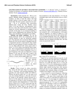
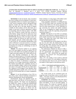
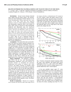
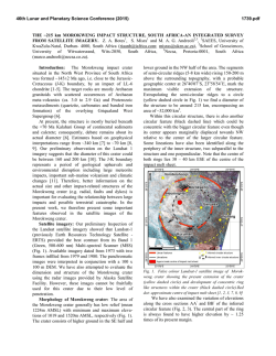
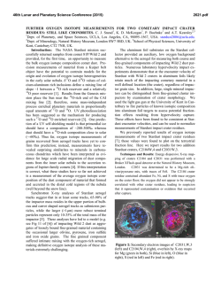
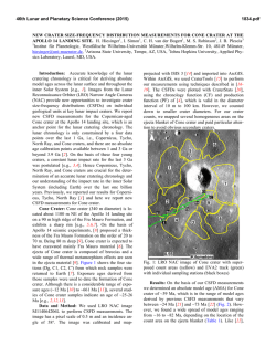
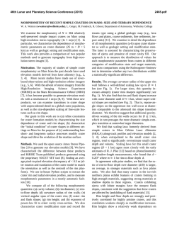
46th Lunar and Planetary Science Conference (2015) 2164.pdf EXPERIMENTAL IMPACTS INTO FELDSPAR PHENOCRYSTS. A. E. Pickersgill1, P. Lindgren, M. Burchell2, M. R. Lee1, D. F. Mark1, M. Price2, 1School of Geographical & Earth Sciences, University of Glasgow, Gregory Building, Lilybank Gardens, Glasgow G12 8QQ, U.K. 2School of Physical Sciences, University of Kent, Canterbury, Kent CT2 7NZ, U.K. ([email protected]). Introduction: Meteorite impact craters are the dominant surface feature on most terrestrial planetary bodies [1]. The extreme temperatures and pressures generated by hypervelocity impact events produce a variety of microscopic shock metamorphic effects in minerals, as well as non-exclusive shock-related features such as pervasive fracturing and brecciation. Studies of shock effects in feldspar group minerals have been limited due to the the comparatively rapid rate at which feldspars weather, and the complexity of their microtextures which renders them difficult to study using conventional optical techniques. However, feldspars are becoming increasingly investigated for use as shock barometers due to their importance in planetary studies and meteoritics, where rocks often contain little or no quartz [e.g., 2]. This provides the motivation to examine more closely the effects of high-velocity impact of a projectile, in the method of [3], into a feldspathic target, in order to the resultant microstructural variation. Geological context: Samples used in this study are blocks of the Shap Granite, from northwest England. The Shap Granite has been widely studied and provides some of the most-well characterized alkalifeldspars on Earth. Normal (unshocked) microtextures in these feldspars are pristine cryptoperthite, pristine microperthite, and veins of patch perthite [4]. These samples were chosen due to the pre-existing in-depth understanding of their microstructures, and the lack of regional deformation resulting in little evidence of tectonically induced strain prior to the impact experiments [e.g. 4, 5]. This study targets alkali feldspar phenocrysts of a size range on the order of 1-3 cm, with bulk composition of ~Or75Ab25 [4]. Phenocrysts are set in a matrix of smaller crystals of alkali feldspar, plagioclase, quartz, and biotite. Methods: Impact experiments were conducted on three target blocks. Two blocks measured 3.5 3.5 2 cm, and one 2 2 1.5 cm. The surfaces were polished flat prior to the experiments. Impacts were carried out at the University of Kent using a horizontally firing two stage light gas gun. The gun is capable of firing millimetre sized projectiles at speeds from 1 to 8.5 km/s. The sequential disruption of two laser light curtains by the projectile during flight permits a determination of the speed of the projectile which is accurate to better than 1% [6]. The projectile does not slow down during flight due to both the gun range and the target chamber being evacuated to a pressure of 20 Pa [6]. All targets were impacted normal to the polished surface using a 0.8 mm stainless steel projectile. The velocity of each shot is as follows: Target A – 1.64 km/s; Target B – 2.94 km/s; Target C – 2.09 km/s. Fig. 1: 3D model of Crater B, approximately 1 cm in diameter, with a green line indicating the crosssectional cut that was made after initial analyses. 3-Dimensional Laser Scanning of the resultant craters was carried out using a NextEngine 3D Scanner HD at the University of Glasgow, with a texture density of 400 DPI and dimensional accuracy of ±0.005 inches. 3D scans were processed using ScanStudio HD and MiniMagics software (Figure 1). Electron Microscopy Analyses were undertaken at the University of Glasgow using a Carl Zeiss Sigma Variable Pressure field emission analytical Scanning Electron Microscope with Oxford Microanalysis. Craters were carbon coated, then studied initially in plan view through backscatter electron (BSE) and secondary electron (SE) imaging at 20 kV and in high vacuum mode. Following these initial analyses, each crater was cut through its centre to make a cross-section as indicated in Figure 1. The cut sections were then polished, carbon coated, and studied again in the SEM via BSE and SE imaging in order to examine microstructural deformation at depth below the crater (Figure 2). Observations: Each of the three impacts listed above resulted in the formation of a small crater, the dimensions of which are summarized in Table 1. None of the targets were completely shattered. Shapes of three craters vary, from equant (B) to extremely elongate (C). The dimensions of A suggest an equant shape, but as the crater overlaps with the edge of the block, it is not possible to measure the true dimensions. 46th Lunar and Planetary Science Conference (2015) 2164.pdf Table 1: Crater dimensions and projectile speed Crater Speed L W D L’ W’ D’ (km/s) (mm) (mm) (mm) A* 1.64 8.5 6.5 2.8 10.6 8.1 3.5 C 2.09 19.1 9.5 2.0 23.9 11.9 2.5 B 2.94 11.4 10.3 1.7 14.3 12.9 2.1 Uncertainty in each dimension is ±0.2 mm. L –the longest dimension; W – the widest dimension orthogonal to L; D – the surface to the deepest point of the crater. L’, W’, D’ – length, width, depth normalized to projectile diameter. *This crater formed over the edge of the block, so the measurements are incomplete and not indicative of a crater formed in an infinite target. Fig. 2: Mosaic of BSE images showing the crosssectional view under the floor of Crater B, where deformation becomes less intense with increasing distance from the crater floor. Light grey is K-feldspar, medium grey is plagioclase, dark grey is quartz. Intense brecciation of the target was observed up to a depth of 760 µm (0.95 projectile diameters) underneath the floor of the crater. The brecciated zone transitions into a zone of intense fracturing which continues to 2 mm (2.5 projectile diameters) below the crater floor. The deepest radial fractures end 4 mm (5.0 projectile diameters) below the crater floor, with a total length of 4.7 mm (5.9 projectile diameters). There were no changes observed in the microstructure of the impacted feldspar crystals. Exsolution lamellae maintained the same orientation and density as in unaffected parts of the crystal (i.e. those farthest from the impact). No melt of any composition was identified, though particulate matter of a similar composition to the impactor was observed in plan view. Future work: Two to three data points are not enough to illuminate statisitically significant trends in the data, so future work will include targeting more feldspar phenocrysts at a wider range of impact speeds. This work will include orienting the crystals differently to the projectile in order to account for the anisotropic strength of the crystal, and will include a wider range of speeds of projectile in order to have greater variation in shock effects produced. References: [1] French B. M. and Koeberl C. (2010) Earth-Sci. Rev. 98:123-170. [2] Jaret S. et al. (2014) MAPS. 49:1007-1022. [3] Lindgren P. et al. (2013) EPSL. 384:71-80. [4] Lee M. R. and Parsons I. (1997) J. Geol. Soc. London. 154:183-188. [5] Waldron K. et al. (1994) Contr. Min. Petr. 116:360-364. [6] Burchell M. et al. (1999) Meas. Sci. Technol. 10:41-50. Acknowledgements: We gratefully acknowledge funding from the Natural Sciences and Engineering Research Council of Canada (NSERC), The Science and Technologies Facility Council (STFC), and the University of Glasgow College of Science and Engineering. We would like to thank P. Chung from the Imaging Spectroscopy and Analysis Centre at the University of Glasgow for assistance with the SEM.
© Copyright 2026