
AEOLIAN SEDIMENT TRANSPORT IN MARTIAN CRATERS. M. D.
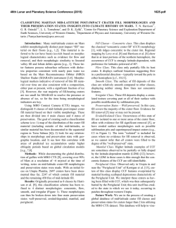
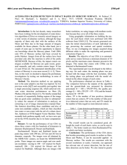
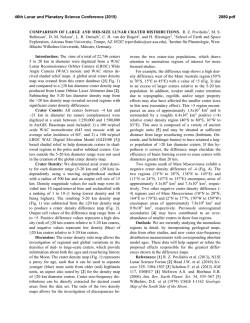
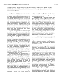
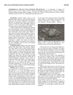
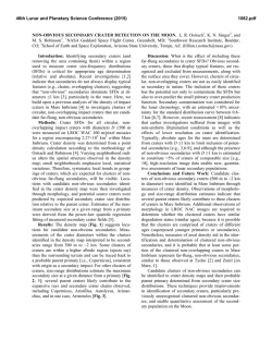
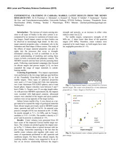
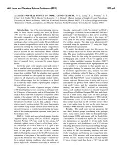
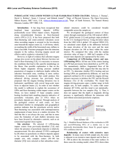
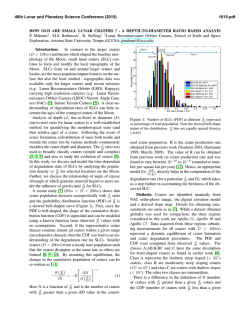
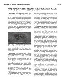
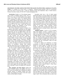
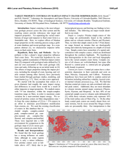
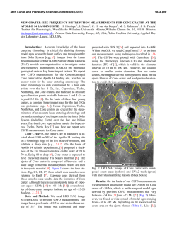
46th Lunar and Planetary Science Conference (2015)
1250.pdf
AEOLIAN SEDIMENT TRANSPORT IN MARTIAN CRATERS. M. D. Day1, W. Anderson2, and G. A. Kocurek1, 1University of Texas at Austin, Department of Geological Sciences, 1 University Station C1100, Austin, TX
78712, [email protected], 2University of Texas at Dallas, Department of Mechanical Engineering.
Introduction: Aeolian erosion and deposition
dominate the modern Martian landscape. As the primary sedimentary basins, craters are critical to understanding the modern Martian sediment budget. Layered
sedimentary rocks have been identified in craters
across Mars, particularly in the ancient southern highlands [1]. These deposits, including the mound currently traversed by the Mars Science Laboratory rover Curiosity, form a variety of morphologies hypothesized to
represent a spectrum of erosional stages reduced from
fully filled craters [1]. These interior layered deposits
have been interpreted as both ancient lacustrine deposits [2], and as dust mounds deposited in place [3].
Yardangs, ventifacts, and dune fields observed in
crater interiors provide evidence that aeolian erosion
and deposition played at least some role in the evolution of these deposit morphologies. The goal of this
work is to determine whether aeolian sediment
transport could have been responsible for the range of
crater interior morphologies observed on Mars today.
Methods: Initially, qualitative wind tunnel experiments were conducted to determine if the erosion patterns observed in previous works could be produced in
laboratory-scale physical models [1]. Model craters
made from an unerodable substrate were filled with
fine sand, dampened for cohesion, and subjected to a
unidirectional 7 m/s wind until all fill had been removed. At this wind speed, comparable to measured
winds on Mars, erosional patterns similar to those observed on Mars changed the morphology of the interior
fill from filling the crater, to forming an initial moat
around the interior of the rim, retreating to a central
mound, isolated butte, and eventually emptying the
crater [1]. Two crater models were used to represent
end member geometries of complex craters (1:10 and
1:30 depth to diameter ratios) [4]. Both models yielded
similar repeatable erosional morphologies. Encouraging results from these experiments motivated further
more quantitative investigation.
Large eddy simulation (LES) was used to model
flow over the two end member geometries also studied
in the wind tunnel. With LES, five deflationary stages
were considered for each end member, thus capturing
key states of the erosional spectrum. Modeled crater
topographies were formed using superimposed Gaussian curves. To reduce computational complexity, all
crater topography sits above a base-level surrounding
plain, and no negative topographic step is modeled
(Fig 1a). LES subjected the craters to a unidirectional
wind regime and predicted shear stress distributions
across the crater domains. Although LES is not typically applied on Earth to systems as large as craters, the
increased depth of the Martian atmospheric boundary
layer relative to Earth suggests larger scale applications [5].
On Mars, once saltation has been initiated, it can be
sustained at shear velocities an order of magnitude
lower than the fluid threshold critical shear velocity
[6]. Time averaged shear velocity distributions resulting from LES were compared with impact threshold
Figure 1: A) Cross sectional profile of an idealized crater topography used in LES. This model represents an intermediate stage of erosion of the interior deposit where an initial moat has been generated around the crater rim interior. The depth to diameter ratio of this model is 1:10, representing a small diameter end member of complex crater
geometries. B) Plan-view of the same crater in A) with colors representing the largest mobile grain size throughout
the domain calculated for 30 m/s winds. Wind is from left to right.
46th Lunar and Planetary Science Conference (2015)
critical shear velocity curves to determine the largest
mobile grain size across each of the ten modeled craters for a range of primary wind speeds (Fig 1b) [6].
Because interactions due to electrostatic forces are
beyond the scope of this analysis, dust sized particles
(d < 50 μm) are not considered.
A survey of Martian craters was conducted using
Viking color and Context Camera (CTX) imagery to
identify craters with interior morphologies undergoing
active aeolian erosion and deposition. The survey was
limited to plus and minus 60° latitude to limit the influence of ice on crater interior morphologies. Guided
by existing surveys, 36 craters with interior layered
deposits were identified with morphologies along the
hypothesized erosional spectrum [7, 8, 1]. Additionally, 76 craters with active interior dune fields were
identified. The low albedo of the dunes indicates an
absence of dust mantling and suggests that these bedforms are actively migrating. High Resolution Imaging
Science Experiment (HiRISE) imagery shows ripples
superimposed on the stoss sides of barchan and crescentic dunes, and additional ripples in regions downwind where dune fields give way to sand sheets.
Associated with many of the observed craters are
low albedo tails emanating from the craters (Fig 2).
Inferring wind direction from slip faces in intra-crater
dune fields, these tails are consistently located downwind of the crater, and elongated in the downwind direction. Previously suggested to be wind streaks, the
dark material mantling the downwind plains is likely
sourced from the similarly low albedo intra-crater dune
fields [9].
Results: Using the largest mobile grain size as a
proxy for transport potential, results from LES modeling indicate that sediment is most readily transported
into craters and around their interior rims, but that only
during high wind events can sediment leave the
downwind end of the crater. This interpretation matches the observations of both layered crater interiors and
interior dune fields. Intra-crater dune fields tend to be
observed as terminal dune fields, trapped at the downwind interior of the crater near the crater rim. Individual dunes are not preserved as sediment is transported
over the rim and out of the crater, but downwind dark
wind streaks suggest that sediment is being excavated.
It is hypothesized that sediment transported from the
sheltered crater interior is thinly dispersed over the
area of the wind streak in thicknesses too slight to form
bedforms that could be resolved by HiRISE.
Though both end member geometries indicated only limited transport out of craters, the 1:10 depth to
diameter ratio models developed a downwind zone of
increased transport relative to their 1:30 counterparts,
1250.pdf
suggesting sediment is more easily excavated from
smaller craters.
The regions of highest transport predicted by LES
correspond with the regions of highest erosion in the
hypothesized erosional spectrum. In addition to the
patterns observed in wind tunnel experiments, LES
generates zones of high shear stress around rim interiors that would cause erosion of any preexisting deposit, creating a positive feedback of erosion, and the
spectrum hypothesized. The abundant yardangs hosted
by many of the observed interior layered deposits support the interpretation of widespread aeolian erosion
inferred from these results.
Results from this study indicate that craters on
modern Mars function as temporary depo-centers,
trapping sediment that then migrates across the crater
to form dune fields and is eventually excavated during
high wind events. Preexisting layered deposits in these
craters could have been subjected to intense abrasion
from trapped sediments, and slowly eroded to produce
the range of morphologies observed today.
50 km
Figure 2: Viking color image of Coimbra crater showing its interior low albedo sandy deposit and downwind wind streak crater tail. Depth to diameter ratio is
approximately 1:30
References: [1] Malin, M. C. and Edgett K. S.
(2000) Science, 290, 1927-1937. [2] Grotzinger, J. P.
et al. (2014) Science, 343, 1242777. [3] Kite E. S. et al.
(2013) Geology, 41, 543-546. [4] Robbins, S. J. and
Hynek B. M. (2012) JRG, 117, E06001. [5] Petrosyan,
A. et al. (2011) Rev. Geophys., 49, RG3005. [6] Kok J.
F. (2010) GRL, 37, L12202. [7] DeLano K. and Hynek
B. M. (2011) LPSC XLII Abstract # 2636. [8] Bennet,
K. A. and Bell, J. F. III (2014) LPSC XLV Abstract #
1539. [9] Edgett K. S. and Malin M. C. (2000)
Geophys. R. Planets, 105, 1623-1650.
© Copyright 2026