
Additional technology objects
 Additional technology objects
___________________
Preface
1
___________________
Part I - Fixed gearing
SIMOTION
SIMOTION SCOUT
Additional technology objects
2
___________________
Part II - Addition object
3
___________________
Part III - Formula object
4
___________________
Part IV - Sensor
5
___________________
Part V - Controller object
Function Manual
Part VI - Temperature
6
___________________
controller
A
___________________
List of abbreviations
02/2012
Legal information
Legal information
Warning notice system
This manual contains notices you have to observe in order to ensure your personal safety, as well as to prevent
damage to property. The notices referring to your personal safety are highlighted in the manual by a safety alert
symbol, notices referring only to property damage have no safety alert symbol. These notices shown below are
graded according to the degree of danger.
DANGER
indicates that death or severe personal injury will result if proper precautions are not taken.
WARNING
indicates that death or severe personal injury may result if proper precautions are not taken.
CAUTION
with a safety alert symbol, indicates that minor personal injury can result if proper precautions are not taken.
CAUTION
without a safety alert symbol, indicates that property damage can result if proper precautions are not taken.
NOTICE
indicates that an unintended result or situation can occur if the relevant information is not taken into account.
If more than one degree of danger is present, the warning notice representing the highest degree of danger will
be used. A notice warning of injury to persons with a safety alert symbol may also include a warning relating to
property damage.
Qualified Personnel
The product/system described in this documentation may be operated only by personnel qualified for the specific
task in accordance with the relevant documentation, in particular its warning notices and safety instructions.
Qualified personnel are those who, based on their training and experience, are capable of identifying risks and
avoiding potential hazards when working with these products/systems.
Proper use of Siemens products
Note the following:
WARNING
Siemens products may only be used for the applications described in the catalog and in the relevant technical
documentation. If products and components from other manufacturers are used, these must be recommended
or approved by Siemens. Proper transport, storage, installation, assembly, commissioning, operation and
maintenance are required to ensure that the products operate safely and without any problems. The permissible
ambient conditions must be complied with. The information in the relevant documentation must be observed.
Trademarks
All names identified by ® are registered trademarks of Siemens AG. The remaining trademarks in this publication
may be trademarks whose use by third parties for their own purposes could violate the rights of the owner.
Disclaimer of Liability
We have reviewed the contents of this publication to ensure consistency with the hardware and software
described. Since variance cannot be precluded entirely, we cannot guarantee full consistency. However, the
information in this publication is reviewed regularly and any necessary corrections are included in subsequent
editions.
Siemens AG
Industry Sector
Postfach 48 48
90026 NÜRNBERG
GERMANY
Copyright © Siemens AG 2012.
All rights reserved
Preface
This document is part of the Description of System and Functions documentation package.
Validity range
This manual applies to SIMOTION SCOUT in association with the SIMOTION Cam or
Cam_ext technology package for product version 4.2.
Chapters in this manual
The following is a list of chapters included in this manual along with a description of the
information presented in each chapter.
● Fixed Gearing (Part I)
Function of fixed gearing technology object
● Addition Object (Part II)
Function of addition objects
● Formula Object (Part III)
Function of formula objects
● Sensor (Part IV)
Function of sensor technology object
● Controller Object (Part V)
Function of controller objects
● Temperature Controller (Part VI)
Function of temperature controllers
● Index
Keyword index for locating information
SIMOTION Documentation
An overview of the SIMOTION documentation can be found in a separate list of references.
This documentation is included as electronic documentation in the scope of delivery of
SIMOTION SCOUT. It comprises 10 documentation packages.
The following documentation packages are available for SIMOTION V4.3:
● SIMOTION Engineering System
● SIMOTION System and Function Descriptions
● SIMOTION Service and Diagnostics
Additional technology objects
Function Manual, 02/2012
3
Preface
● SIMOTION IT
● SIMOTION Programming
● SIMOTION Programming - References
● SIMOTION C
● SIMOTION P
● SIMOTION D
● SIMOTION Supplementary Documentation
Hotline and Internet addresses
Additional information
Click the following link to find information on the the following topics:
● Ordering documentation/overview of documentation
● Additional links to download documents
● Using documentation online (find and search in manuals/information)
http://www.siemens.com/motioncontrol/docu
Please send any questions about the technical documentation (e.g. suggestions for
improvement, corrections) to the following e-mail address:
[email protected]
My Documentation Manager
Click the following link for information on how to compile documentation individually on the
basis of Siemens content and how to adapt this for the purpose of your own machine
documentation:
http://www.siemens.com/mdm
Training
Click the following link for information on SITRAIN - Siemens training courses for automation
products, systems and solutions:
http://www.siemens.com/sitrain
FAQs
Frequently Asked Questions can be found in SIMOTION Utilities & Applications, which are
included in the scope of delivery of SIMOTION SCOUT, and in the Service&Support pages
in Product Support:
http://support.automation.siemens.com
Additional technology objects
4
Function Manual, 02/2012
Preface
Technical support
Country-specific telephone numbers for technical support are provided on the Internet under
Contact:
http://www.siemens.com/automation/service&support
Additional technology objects
Function Manual, 02/2012
5
Preface
Additional technology objects
6
Function Manual, 02/2012
Table of contents
Preface ...................................................................................................................................................... 3
1
2
3
Part I - Fixed gearing ............................................................................................................................... 11
1.1
1.1.1
Overview of Fixed Gearing ..........................................................................................................11
Function overview ........................................................................................................................11
1.2
1.2.1
1.2.2
1.2.3
1.2.4
Configuring the fixed gearing .......................................................................................................13
Creating fixed gearing..................................................................................................................13
Assigning parameters/defaults for fixed gearing..........................................................................15
Configuring a fixed gearing ..........................................................................................................16
Interconnecting a fixed gearing....................................................................................................19
1.3
1.3.1
1.3.1.1
1.3.1.2
1.3.2
1.3.3
1.3.4
1.3.4.1
1.3.4.2
Programming fixed gearing/references........................................................................................20
Programming................................................................................................................................20
Overview of commands ...............................................................................................................20
Commands...................................................................................................................................21
System variables..........................................................................................................................23
Local alarm response...................................................................................................................24
Menus ..........................................................................................................................................24
Fixed gearing - menu ...................................................................................................................24
Fixed gearing - context menu ......................................................................................................25
Part II - Addition object ............................................................................................................................ 27
2.1
2.1.1
Overview of Addition Object.........................................................................................................27
Function overview ........................................................................................................................27
2.2
2.2.1
2.2.2
2.2.3
2.2.4
Configuring an Addition Object ....................................................................................................29
Creating an addition object ..........................................................................................................29
Assigning parameters/defaults to an addition object ...................................................................31
Configuring an addition object .....................................................................................................32
Interconnecting an addition object ...............................................................................................35
2.3
2.3.1
2.3.1.1
2.3.1.2
2.3.2
2.3.3
2.3.4
2.3.4.1
2.3.4.2
Programming an Addition Object/References .............................................................................36
Programming................................................................................................................................36
Overview of commands ...............................................................................................................36
Commands...................................................................................................................................37
System variables..........................................................................................................................37
Local alarm response...................................................................................................................38
Menus ..........................................................................................................................................39
Addition object - menu .................................................................................................................39
Addition object - context menu.....................................................................................................40
Part III - Formula object ........................................................................................................................... 41
3.1
3.1.1
Overview of Formula Object ........................................................................................................41
Function overview ........................................................................................................................41
3.2
3.2.1
3.2.2
Configuring a Formula Object ......................................................................................................44
Creating a formula object.............................................................................................................44
Assigning parameters/defaults to a formula object......................................................................46
Additional technology objects
Function Manual, 02/2012
7
Table of contents
4
5
3.2.3
3.2.4
3.2.5
Configuring a formula object ....................................................................................................... 48
Interconnecting a formula object................................................................................................. 50
Defining a formula ....................................................................................................................... 51
3.3
3.3.1
3.3.1.1
3.3.1.2
3.3.2
3.3.3
3.3.4
3.3.5
3.3.6
3.3.6.1
3.3.6.2
Programming a Formula Object/References .............................................................................. 52
Programming............................................................................................................................... 52
Overview of commands............................................................................................................... 52
Commands .................................................................................................................................. 53
Rules for definition of formulas ................................................................................................... 55
Available functions in formulas (formula operators).................................................................... 57
System variables......................................................................................................................... 59
Local alarm response.................................................................................................................. 62
Menus.......................................................................................................................................... 63
Formula object - menu ................................................................................................................ 63
Formula object - context menu ................................................................................................... 64
3.4
Example ...................................................................................................................................... 65
Part IV - Sensor ....................................................................................................................................... 71
4.1
4.1.1
Overview of Sensor..................................................................................................................... 71
Function overview ....................................................................................................................... 71
4.2
4.2.1
4.2.2
4.2.3
Fundamentals of sensors............................................................................................................ 73
Function in principle .................................................................................................................... 73
Measured value........................................................................................................................... 74
Function in detail ......................................................................................................................... 74
4.3
4.3.1
4.3.2
Configuring sensors .................................................................................................................... 76
Creating a sensor object ............................................................................................................. 76
Configuring a sensor ................................................................................................................... 78
4.4
4.4.1
4.4.1.1
4.4.1.2
4.4.2
4.4.3
4.4.4
4.4.4.1
4.4.4.2
Programming a Sensor/References............................................................................................ 80
Programming............................................................................................................................... 80
Overview of commands............................................................................................................... 80
Commands .................................................................................................................................. 80
System variables......................................................................................................................... 81
Local alarm response.................................................................................................................. 82
Menus.......................................................................................................................................... 83
Sensor - menu............................................................................................................................. 83
Sensor - context menu ................................................................................................................ 83
Part V - Controller object.......................................................................................................................... 85
5.1
5.1.1
Overview of Controller Object ..................................................................................................... 85
Function overview ....................................................................................................................... 85
5.2
5.2.1
Fundamentals of Controller Object ............................................................................................. 87
Description of function................................................................................................................. 87
5.3
5.3.1
5.3.2
5.3.3
5.3.4
5.3.5
Configuring a Controller Object................................................................................................... 89
Creating a controller object ......................................................................................................... 89
Assigning parameters/defaults to a controller object .................................................................. 91
Configuring a controller object .................................................................................................... 92
Configuring closed-loop control .................................................................................................. 94
Interconnecting a controller object .............................................................................................. 96
5.4
Programming a Controller Object/References ............................................................................ 97
Additional technology objects
8
Function Manual, 02/2012
Table of contents
5.4.1
5.4.1.1
5.4.1.2
5.4.2
5.4.3
5.4.3.1
5.4.3.2
6
A
Programming................................................................................................................................97
Overview of commands ...............................................................................................................97
Commands...................................................................................................................................98
Local alarm response...................................................................................................................99
Menus ..........................................................................................................................................99
Controller object - menu...............................................................................................................99
Controller object - context menu ................................................................................................100
Part VI - Temperature controller ............................................................................................................ 103
6.1
6.1.1
Overview of Temperature Controller..........................................................................................103
Function overview ......................................................................................................................103
6.2
6.2.1
6.2.2
Fundamentals of Temperature Controller..................................................................................103
Principles of operation for a temperature controller (temperature channel TO) ........................103
Functional scope........................................................................................................................104
6.3
6.3.1
6.3.2
6.3.3
6.3.3.1
6.3.3.2
6.3.3.3
6.3.3.4
6.3.3.5
6.3.3.6
6.3.3.7
Configuring the Temperature Controller ....................................................................................107
Creating a temperature controller ..............................................................................................107
Configuring the temperature controller in the expert list............................................................108
Configuring a temperature controller .........................................................................................109
Operating parameters (.generalParameter)...............................................................................109
Configuration data for the analog input......................................................................................110
Configuration data for the controller ..........................................................................................115
Configuration data for identification ...........................................................................................121
Output handling of measured values .........................................................................................123
Specification of limit values........................................................................................................124
System cycle clocks and execution speed ................................................................................125
List of abbreviations............................................................................................................................... 131
A.1
List of abbreviations ...................................................................................................................131
Index...................................................................................................................................................... 133
Additional technology objects
Function Manual, 02/2012
9
Table of contents
Additional technology objects
10
Function Manual, 02/2012
Part I - Fixed gearing
1.1
Overview of Fixed Gearing
1.1.1
Function overview
1
The Fixed gear technology object enables you to implement fixed synchronous operation
(without synchronization/desynchronization) based on a specified gear ratio.
A Fixed gear converts an input variable into an output variable with a configured
transmission ratio (gear ratio).
A Fixed gear is interconnected to a motion vector on the input side and the output side.
The basic functionality is the multiplication of the input vector by the configured gear ratio.
The individual vector components are thereby multiplied by the gear factor.
Both absolute and relative synchronous operation, with or without offset are possible.
Offset changes, gear changes, and input changeovers are directly enabled.
An on-the-fly master value change is possible (direct transition).
No limiting operations, no transition phases, and no corrections (except the offset value) are
taken into account.
You can connect the output interface to a position axis and activate the acceptance of the
output values of the fixed gear on the axis with the TO functions _runpositionbasedmotionin
or _runvelovitybasedmotionin.
Application
A Fixed gear TO can, for example, be used as follows:
● To make allowance for diameters in a master variable
● To implement a fixed gear ratio without clutch
● As a parallel gear on the master,
slaves are "hung" or "unhung".
Thus, the gear is always synchronous with the master.
Example: A paper web also runs in synchronism with the master.
Additional technology objects
Function Manual, 02/2012
11
Part I - Fixed gearing
1.1 Overview of Fixed Gearing
Interconnection
*HDUUDWLR
2IIVHW
0RWLRQ,Q
2IIVHW
[
0RWLRQ2XW
)L[HGJHDU
Figure 1-1
Fixed gear object model
A Fixed gear object has one input and one output.
The input vector is type MotionIn and the output vector type MotionOut. These vectors
comprise the components distance (s), velocity (v) and acceleration (a).
Note
For additional information, please refer to the following manuals:
Function Manual Motion Control Basic Functions, "Interconnection of Technology Objects"
Function Manual Motion Control Technology Objects Axis, Electric/Hydraulic, External
Encoder, "Traversing using Motion Vectors"
Gear ratio
The gear ratio can be specified selectively as a rational value (LREAL) or as a ratio of two
32-bit numbers (DINT) in the form of a numerator/denominator.
The gear ratio can be changed using functions or commands.
Offset
An offset can be specified on both the input side and output side.
An offset only applies in position-related synchronous operation.
The offset is specified in the set user-defined unit.
It is possible to adjust the slave position by setting the master or slave offset. The difference
between the two is as follows:
● Master offset: The gear ratio is included in the offset.
● Slave offset: The gear ratio is not included in the offset.
Additional technology objects
12
Function Manual, 02/2012
Part I - Fixed gearing
1.2 Configuring the fixed gearing
Units
Units can be set on the Fixed gear TO and they apply to both the input and output side.
Example: Axis 1 - Fixed gear - Axis 2
● The units are set to [mm] for axis 1.
● The units are set to [m] for the Fixed gear.
● The units are set to [m] for axis 2.
This means, for example, that a position of three millimeters on axis 1 corresponds to three
meters on the input interface of the Fixed gear.
1.2
Configuring the fixed gearing
1.2.1
Creating fixed gearing
Fixed gearing technology objects are stored across-the-board for a device in the
TECHNOLOGY folder. They can be interconnected with suitable technology objects of the
device.
Additional technology objects
Function Manual, 02/2012
13
Part I - Fixed gearing
1.2 Configuring the fixed gearing
Proceed as follows
1. To create a new Fixed Gearing TO, double-click Insert fixed gearing under
TECHNOLOGY in the project navigator.
You can also copy an existing Fixed Gearing TO using the clipboard and insert it under
another name.
Figure 1-2
Representation of fixed gears in the project navigator
Figure 1-3
Inserting a fixed gear
2. Enter a name and, if necessary, the author, version, and comments, and click OK to
confirm.
The new fixed gear TO will be inserted under TECHNOLOGY.
Additional technology objects
14
Function Manual, 02/2012
Part I - Fixed gearing
1.2 Configuring the fixed gearing
1.2.2
Assigning parameters/defaults for fixed gearing
Proceed as follows
In the project navigator, double-click Defaults under the object.
Figure 1-4
Fixed gear TO: Defaults
Fixed gearing - defaults
Specify the parameters (defaults) for calling the fixed gear in this window
(_enableFixedGearing or _disableFixedGearing).
If you do not make any additional specifications during programming, these default values
will be used.
You can set the following parameters:
Table 1- 1
Fixed gear TO: Parameters that can be set for default purposes
Field/Button
Explanation/Instruction
Direction
Here, you specify the direction of the gearing.
Gear type
Here, you select the gear type (absolute or relative).
Gear ratio mode
Here, you specify the gear ratio mode. Depending on the selected mode,
additional parameters are displayed as a rational value (LREAL) or as a ratio
of two 32-bit numbers (DINT) in the form of a numerator/denominator.
Numerator
Here, you can enter the numerator of the gear ratio in the form of a
numerator/denominator ratio.
Denominator
Here, you can enter the denominator of the gear ratio in the form of a
numerator/denominator ratio.
Additional technology objects
Function Manual, 02/2012
15
Part I - Fixed gearing
1.2 Configuring the fixed gearing
Field/Button
Explanation/Instruction
Activation
Here, you specify the activation method for fixed synchronous operation.
Master value position
Here, you enter the position of the master value for activation.
Deactivation
Here, you specify the deactivation method for fixed synchronous operation.
Master value position
Here, you enter the position of the master value for deactivation.
For additional information on the meaning of parameters and their permissible value ranges,
please see the SIMOTION Reference Lists.
See also
Function overview (Page 11)
Overview of commands (Page 20)
1.2.3
Configuring a fixed gearing
Procedure
In the project navigator, double-click Configuration under the object.
Figure 1-5
Configuring a fixed gearing
Additional technology objects
16
Function Manual, 02/2012
Part I - Fixed gearing
1.2 Configuring the fixed gearing
Figure 1-6
Configuring modulo properties of the output of a fixed gear
Fixed gearing - configuration
In this window, specify the configuration of the input and the output.
You can set the following parameters:
Field/Button
Explanation/instructions
Name
Display: name of the fixed gearing
Ignore position
If the check box is selected, the velocity will be used as the gearing basis.
Configuration
Here, you set the units: linear or rotary
These apply to the output side. On the input side, the values are applied with
their units, or are displayed without units.
Processing cycle
clock
Here, you select the IPO cycle clock or IPO_2 cycle clock.
Input side
Here, you specify the validity of the input values or default values.
Output side
Here, you specify the modulo properties of the output. If the check box is
selected, the parameters will be displayed.
For additional information on the meaning of parameters and their permissible value ranges,
please see the SIMOTION reference lists.
See also
Function overview (Page 11)
Overview of commands (Page 20)
Gearing basis
The gearing basis (configuration data element motionBase) must be specified, i.e.,
● Position (POSITION):
Multiplication of position, velocity, acceleration (s, v, a)
● Velocity (VELOCITY):
Multiplication of velocity, acceleration (v, a)
All components are present in the output vector. When Velocity is specified as the gearing
basis, the position component in the output vector is set to zero.
Any existing offset is applied to the variable specified by the motion basis.
Additional technology objects
Function Manual, 02/2012
17
Part I - Fixed gearing
1.2 Configuring the fixed gearing
Modulo properties
The output-side modulo setting is derived from the system or can be set using configuration
data element MotionOut.modulo.
● The modulo setting is derived from the downstream TO with system default (SYSTEM) if
this TO and its modulo properties can be uniquely determined. (A formula object, for
example, does not have any modulo properties.)
● In all other cases, the modulo property set on the TO is used (DIRECT).
Additional technology objects
18
Function Manual, 02/2012
Part I - Fixed gearing
1.2 Configuring the fixed gearing
1.2.4
Interconnecting a fixed gearing
Procedure
1. In the project navigator, double-click Interconnections under the object.
Figure 1-7
Interconnecting a fixed gearing
In this window, interconnect the input of the fixed gear (with axes, for example).
2. To do so, click in the corresponding input field and then select the desired object. (The
objects must have already been created.)
Figure 1-8
Interconnecting a fixed gear with an axis
Note
The interconnection with a cam profile is intended for a later software version and has no
function in Version V3.2.
Additional technology objects
Function Manual, 02/2012
19
Part I - Fixed gearing
1.3 Programming fixed gearing/references
Note
For additional information, please refer to the following manuals:
Function Manual Motion Control Basic Functions, "Interconnection of Technology
Objects"
Function Manual Motion Control Technology Objects Axis, Electric/Hydraulic, External
Encoder, "Traversing using Motion Vectors"
1.3
Programming fixed gearing/references
1.3.1
Programming
1.3.1.1
Overview of commands
Table 1- 2
Fixed gearing TO: Overview of commands
Command
Functionality
_enableFixedGearMotionIn
Enabling/disabling of the input vector
_disableFixedGearMotionIn
_enableFixedGearing
Activation/deactivation of fixed gear
_disableFixedGearing
_setFixedGearingOffset
Set offset on the input side/output
side
_setFixedGearMaster
Switch over master value
_resetFixedGear
Reset gear
_resetFixedGearError
Reset error
_resetFixedGearConfigDataBuffer
Delete collected configuration data
_bufferFixedGearCommandId
Store CommandId and command status temporarily
_removeBufferedFixedGearCommandId
Delete CommandId
_getStateOfFixedGearCommand
Read out command status
_getFixedGearErrorNumberState
Read out error number status
Note
For a complete list of all commands and their syntax, the system variables, and error
messages, please see the SIMOTION Reference Lists.
Additional technology objects
20
Function Manual, 02/2012
Part I - Fixed gearing
1.3 Programming fixed gearing/references
1.3.1.2
Commands
Activation/deactivation of the input vector
Note
The interconnection interfaces on the input side are enabled/disabled separately from the
functionality.
If the input values are inactive, the default values are applied.
● _enableFixedGearMotionIn: Use interconnected input values
● _disableFixedGearMotionIn: Disable interconnected input values;
the default values will be used (motionInDefault and motionOutDefault system variables).
The commands are synchronous.
The input and the output are active following controller power-up, if they are interconnected.
A status check is possible via the motionIn.state and motionOut.state system variables.
If the input and the output are not interconnected, an error is output. (The alarm is not
generated until _enable...In.)
Enabling/disabling of fixed gearing
● _enableFixedGearing: Enable gearing functionality
The command is synchronous.
– The gearing is started with _enableFixedGearing without a transition function.
– The gearing ratio is specified in the function parameter.
– The startPosition... parameter acts only if Position is selected as the gearing basis.
● _disableFixedGearing: Disable gearing functionality
– The gearing is started with _disableFixedGearing without a transition function.
– The values of the interconnection values on the output side depend on the
motionOutBehaviourMode parameter of the _disableFixedGearing() command.
The following can be set for _disableFixedGearing:
● Freeze value
● Define default value
● Input a value of "0.0"
Additional technology objects
Function Manual, 02/2012
21
Part I - Fixed gearing
1.3 Programming fixed gearing/references
Absolute or relative gearing
The fixed gearing can be set to absolute or relative gearing with the gearingType parameter
of the _enableFixedGearing command.
● With absolute synchronous operation (ABSOLUTE), the input and output values are
interpreted "absolutely", i.e., directly coupled.
● With relative synchronous operation (RELATIVE), the input and output are interpreted
"relatively", i.e., coupled with an offset.
Direction
The gear ratio can be set to positive or negative (corresponding to a negative gear ratio) with
the direction parameter of the _enableFixedGearing command.
● POSITIVE means that the axes are running in the same direction.
● NEGATIVE means that the axes are running in opposite directions.
Validity of input values or default values
The interconnected values are enabled/disabled using a command
(_enableFixedGearMotionIn/_disableFixedGearMotionIn).
Configuration data element MotionIn.behaviorByInvalidInterface can be used to specify
which of the following values is used if the interconnection values are enabled but invalid:
● Most recent valid value (LAST_VALID_INTERFACE_VALUE) or
● Replacement values (DEFAULT_VALUE)
(Following system startup, the most recent valid value is 0).
When the interconnection interface on the input side is disabled, the default value is applied.
Setting offset on the input side/output side
_setFixedGearingOffset: Shifts the gearing relative to the master value or slave value.
The offset can be changed over using the activationMode parameter of the
_setFixedGearingOffset command. The changeover applies as follows:
● For the next synchronous operation and all subsequent synchronous operations if
DEFAULT_VALUE is set
● For the current synchronous operation only if ACTUAL_VALUE is set
● For the current synchronous operation and all subsequent synchronous operations if
ACTUAL_AND_DEFAULT_VALUE is set
An offset with reference to the current synchronous operation is retained only for the duration
of the _enableFixedGearing, that is, the offset is directly assigned to the active
_enableFixedGearing command.
The current offset is applied without a compensatory motion, i.e., it is applied directly.
Additional technology objects
22
Function Manual, 02/2012
Part I - Fixed gearing
1.3 Programming fixed gearing/references
Switch over master value
The active master can be switched over online by means of _setFixedGearingMaster.
1.3.2
System variables
The input and output values of a fixed gearing TO can be read out via system variables.
Table 1- 3
Fixed gearing TO: System variables
System variable
Type
Description
motionIn
StructFixedGearMotionIn
StructMotionVector
The input vector
Components of the must be
interconnected.
input vector
s
LREAL
Position
v
LREAL
Velocity
a
LREAL
Acceleration
EnumActiveInactive
Status
value
state
lastValidInterface
value
input vector
StructMotionVector
Last valid values
s
LREAL
Position
v
LREAL
Velocity
a
LREAL
Acceleration
EnumInterfaceValueDefaultValue
Validity
motionInDefault
StructMotionVector
Default values for
input vector
motionOut
StructFixedGearMotionOut
Output vector
StructMotionVector
Components of the
output vector
s
LREAL
Position
v
LREAL
Velocity
a
LREAL
Acceleration
StructMotionVector
Function result
gearing
s
LREAL
Position
v
LREAL
Velocity
a
LREAL
Acceleration
StructMotionVector
Default values for
output vector
validity
value
fixedGearValue
motionOutDefault
Remark
Can only be read
Deactivate with
function, see
_disable
FixedGearing
Additional technology objects
Function Manual, 02/2012
23
Part I - Fixed gearing
1.3 Programming fixed gearing/references
1.3.3
Local alarm response
Technological alarms
The standard technology object alarms, e.g., interconnection error, illegal parameter, are
output.
Local responses
If an error occurs, the following local responses are possible:
● No response (NONE)
● Stop TO processing (DISABLE)
● Stop command decoding (DECODE_STOP)
The local reactions can be set under TechnologicalFaultTask in the alarm configuration.
1.3.4
Menus
1.3.4.1
Fixed gearing - menu
Grayed-out functions cannot be selected.
You can select the following functions:
Function
Meaning/Note
Close
Use this function to close the active window in
the working area.
Properties
Properties displays the properties of the fixed
gearing selected in the project navigator.
You can enter the object name plus author and
version in this window.
Configuration
This function opens the configuration for the
fixed gearing selected in the project navigator.
In this window, specify the configuration of the
input and the output.
Factory setting (default)
This function opens the defaults for the fixed
gearing selected in the project navigator.
In this window, specify the parameters for the
call of the fixed gearing object
(_enableFixedGearing or
_disableFixedGearing).
Additional technology objects
24
Function Manual, 02/2012
Part I - Fixed gearing
1.3 Programming fixed gearing/references
Function
Meaning/Note
Interconnections
This function opens the interconnections for the
fixed gearing selected in the project navigator.
In this window, interconnect the input of the
fixed gearing object, e.g. to axes.
Expert
Expert list
This function opens the submenu for the expert
settings.
This function opens the expert list for the fixed
gearing selected in the project navigator.
The configuration data and system variables
can be displayed and changed in this list.
See Basic functions - expert list
Configure Units
This function opens the Configure Object Units
window in the working area.
You can configure the units used for the
selected object here.
1.3.4.2
Fixed gearing - context menu
Grayed-out functions cannot be selected.
You can select the following functions:
Function
Meaning/Note
Open configuration
This function opens the configuration for the
fixed gearing selected in the project navigator.
In this window, specify the configuration of the
input and the output.
Factory setting (default)
This function opens the defaults for the fixed
gearing selected in the project navigator.
In this window, specify the parameters for the
call of the fixed gearing object
(_enableFixedGearing or
_disableFixedGearing).
Interconnections
This function opens the interconnections for the
fixed gearing selected in the project navigator.
In this window, interconnect the input of the
fixed gearing object, e.g. to axes.
Expert
Expert list
This function opens the submenu for the expert
settings.
This function opens the expert list for the fixed
gearing selected in the project navigator.
The configuration data and system variables
can be displayed and changed in this list.
See Basic functions - expert list
Additional technology objects
Function Manual, 02/2012
25
Part I - Fixed gearing
1.3 Programming fixed gearing/references
Function
Configure Units
Meaning/Note
This function opens the Configure Object Units
window in the working area.
You can configure the units used for the
selected object here.
Import object
Use Import object to open a window for the
XML import.
You can define the parameters for the XML
import in this window.
Save project and export object
Use Save project and export object to open a
window for an XML export.
You can define the parameters for the XML
export in this window.
Additional technology objects
26
Function Manual, 02/2012
2
Part II - Addition object
2.1
Overview of Addition Object
2.1.1
Function overview
The addition object technology object enables you to add up to four input vectors for one
output vector.
The input vectors are type MotionIn and the output vector is type MotionOut.
There are no limitations on the addition object. Transitional phases are not taken into
account for non-continuous input signals.
Application
An addition object can, for example, be used as follows:
● For adding superimpositions/offsets in the main signal path,
e.g., color register, cut-off register to the paper web
Interfaces
0RWLRQ,QYHFWRU
0RWLRQ,QYHFWRU
0RWLRQ,QYHFWRU
Σ
0RWLRQ2XWYHFWRU
0RWLRQ,QYHFWRU
$GGLWLRQREMHFW
Figure 2-1
Object model for addition object
An addition object calculates the sum of the four input vectors.
The values of the respective input vectors are generated from the interconnection values, the
most recent valid interconnection values, or the replacement values.
An interconnected input vector is activated/deactivated using a command; otherwise, the
replacement value is applied.
The output vector can be activated or deactivated (frozen).
Additional technology objects
Function Manual, 02/2012
27
Part II - Addition object
2.1 Overview of Addition Object
Interconnection
The first input must be interconnected, while the other inputs and the output may be
interconnected.
The first input vector determines which technology variables are added up and are relevant
in the output vector.
Non-interconnected input vectors can be specified by means of system variables from the
user program.
The input vectors can be interconnected once only ('single point') and cannot be changed
over; the output vector can be interconnected any number of times ('multi-point').
Note
For additional information, please refer to the following manuals:
Function Manual Motion Control Basic Functions, "Interconnection of Technology Objects"
Function Manual Motion Control Technology Objects Axis, Electric/Hydraulic, External
Encoder, "Traversing using Motion Vectors"
Modulo properties
The variables to be added can be modulo variables.
The output vector can be a modulo variable.
The input modulo lengths and the output modulo length can be different.
The modulo relationships can be specified in the addition object on the output side.
The output modulo length is derived from the output-side interconnection, or it can be directly
specified (configuration setting).
Subtraction
Subtractions are possible for each input through configuration (inversion).
Units
Units can be set on the addition object, they apply to both the input and output side.
Example: Axis 1, 2 - Addition object - Axis 3
● The units are set to [mm] for axes 1 and 2.
● The units are set to [m] for the addition object.
● The units are set to [m] for axis 2.
This means, for example, that a position of three millimeters on axis 1 corresponds to three
meters on the input interface of the addition object.
Additional technology objects
28
Function Manual, 02/2012
Part II - Addition object
2.2 Configuring an Addition Object
2.2
Configuring an Addition Object
2.2.1
Creating an addition object
Addition objects are stored across-the-board for a device in the TECHNOLOGY folder. They
can be interconnected with suitable technology objects of the device.
Proceed as follows
1. To create a new addition object, double-click Insert addition object under TECHNOLOGY
in the project navigator.
You can also copy an existing addition object to the clipboard and then insert it under
another name.
Figure 2-2
Representation of addition objects in the project navigator
Additional technology objects
Function Manual, 02/2012
29
Part II - Addition object
2.2 Configuring an Addition Object
Figure 2-3
Inserting an addition object
2. Enter a name and, if necessary, the author, version, and comments, and click OK to
confirm.
The new addition object will be inserted under TECHNOLOGY.
Additional technology objects
30
Function Manual, 02/2012
Part II - Addition object
2.2 Configuring an Addition Object
2.2.2
Assigning parameters/defaults to an addition object
Procedure
In the project navigator, double-click Defaults under the object.
Figure 2-4
Addition object: Defaults
Specify the replacement values (defaults) for calling the addition object in this window
(_enableAdditionObject or _disableAdditionObject).
Addition object - defaults
Specify the input default values (defaults) for calling the addition object in this window
(_enableAdditionObject or _disableAdditionObject).
Field/Button
Explanation/instructions
Input connector
Motion inputs 1 to 4
Default value for
Input values are generated from the
interconnected values, the most recent valid
interconnected values, or the default values.
Position, velocity, and acceleration can each be
specified with default values.
Default value
Here, you enter the default values.
For additional information on the meaning of parameters and their permissible value ranges,
please see the SIMOTION reference lists.
Additional technology objects
Function Manual, 02/2012
31
Part II - Addition object
2.2 Configuring an Addition Object
See also
Function overview (Page 27)
Overview of commands (Page 36)
2.2.3
Configuring an addition object
Proceed as follows
In the project navigator, double-click Configuration under the object.
Figure 2-5
Configuring an addition object
Figure 2-6
Configuring modulo properties of the output of an addition object
Addition object - configuration
In the displayed window, specify the configuration of the inputs and the output.
Additional technology objects
32
Function Manual, 02/2012
Part II - Addition object
2.2 Configuring an Addition Object
You can set the following parameters:
Table 2- 1
Addition object TO: Parameters that can be set for configuration purposes
Field/Button
Explanation/instructions
Name
Display: name of addition object
Ignore position
If the check box is selected, the velocity will be used as the addition basis.
Configuration
Here, you set the units: linear or rotary
Processing cycle
clock
Here, you select the IPO cycle clock or IPO_2 cycle clock.
Input side
Here, you specify the input inversion and the validity of the input values/default
values.
Output side
Here, you specify the modulo property of the output. If the check box is
selected, the parameters will be displayed.
For additional information on the meaning of parameters and their permissible value ranges,
please see the SIMOTION reference lists.
See also
Function overview (Page 27)
Overview of commands (Page 36)
Addition basis
The addition basis (configuration data element motionBase) must be specified, i.e.,
● Position (POSITION):
Addition of position, velocity, acceleration (s, v, a)
● Velocity (VELOCITY):
Addition of velocity, acceleration (v, a)
All input vectors are given the same addition basis.
Only the relevant vector components are then valid in the output vector. The other
components are set to zero.
Comment:
A component can be added up selectively in the motion vector, e.g. torque, using a formula
object.
Additional technology objects
Function Manual, 02/2012
33
Part II - Addition object
2.2 Configuring an Addition Object
Units
The following basic units are available for representing lengths:
● Linear
● Rotary
● No unit
The unit settings apply on the output side. On the input side, the values are added without
consideration as to agreement of the units.
That is, all system variables acting on the output side have the configured unit, while all
system variables acting on the input side are unitless.
Modulo properties
The output-side modulo setting is derived from the system or can be set using configuration
data element MotionOut.modulo:
● The "Detect automatically" setting checks the uniqueness of the interconnection(s) on the
output side.
If a unique assignment is possible, the information is used for representing the output
vector.
If the object interconnected on the output side has a modulo representation, the output
vector is already calculated in this modulo representation.
If a unique assignment is not possible, no adaptation is performed; rather, an error/alarm
is output.
● The "Determine from configuration" setting enables a modulo representation to be
selected for the output vector itself.
Input inversion
Configuration data element MotionIn#.invert can be used to configure a signal inversion for
each input prior to addition.
The inversion applies to position, velocity, or acceleration.
The input-side system variable (motionIn#) displays the inverted value or writes the value
after inversion.
Additional technology objects
34
Function Manual, 02/2012
Part II - Addition object
2.2 Configuring an Addition Object
2.2.4
Interconnecting an addition object
Procedure
1. In the project navigator, double-click Interconnections under the object.
Figure 2-7
Interconnecting an addition object
In the displayed window, interconnect the inputs of the addition object (with axes, for
example).
2. To do so, click in the corresponding input field and then select the desired object. (The
objects must have already been created.)
Figure 2-8
Interconnecting an addition object with axes
Additional technology objects
Function Manual, 02/2012
35
Part II - Addition object
2.3 Programming an Addition Object/References
Note
For additional information, please refer to the following manuals:
Function Manual Motion Control Basic Functions, "Interconnection of Technology
Objects"
Function Manual Motion Control Technology Objects Axis, Electric/Hydraulic, External
Encoder, "Traversing using Motion Vectors"
2.3
Programming an Addition Object/References
2.3.1
Programming
2.3.1.1
Overview of commands
Table 2- 2
Addition object TO: Overview of commands
Command
Functionality
_enableAdditionObjectIn
Enabling and disabling input vectors
_disableAdditionObjectIn
_changeEnableModeOfAdditionObject
Simultaneous switchover
_resetAdditionObject
Reset addition object
_resetAdditionObjectError
Reset error
_resetAdditionObjectConfigDataBuffer
Delete collected configuration data
_bufferAdditionObjectCommandId
Store CommandId and command status temporarily
_removeBufferedAdditionObjectCommandId
Delete CommandId
_getStateOfAdditionObjectCommand
Read out command status
_getAdditionObjectErrorNumberState
Read out error number status
Note
For a complete list of all commands and their syntax, the system variables, and error
messages, please see the SIMOTION Reference Lists.
Additional technology objects
36
Function Manual, 02/2012
Part II - Addition object
2.3 Programming an Addition Object/References
2.3.1.2
Commands
Enabling and disabling input vectors
● _enableAdditionObjectIn: Enable input vectors
● _disableAdditionObjectIn: Deactivate input vectors
The commands are synchronous.
All four input vectors can be enabled/disabled simultaneously with one command.
All of the inputs are always added.
Input values are generated from the interconnected values, the most recent valid
interconnected values, or the default values.
● If interconnection values are not enabled, the default values are applied.
● If the interconnection interfaces on the input side are disabled, the most recent valid
values or the default values are also used.
The inputs and the output are active following controller power-up if they are interconnected.
(The status can be scanned using a system variable.)
If the inputs and the output are not interconnected, an error is output. (The alarm is not
generated until _enable...In.)
Validity of input values or default values
Configuration data element MotionIn#.behaviorByInvalidInterface can be used to specify
which of the following values is used if the interconnection values are enabled but invalid:
● Most recent valid value (LAST_VALID_INTERFACE_VALUE)
or
● Replacement values (DEFAULT_VALUE)
(Following system startup, the most recent valid value is 0).
2.3.2
System variables
The input and output values of an addition object can be read out via system variables.
Table 2- 3
Addition object TO: System variables
System variable
Type
Description
Remark
StructAdditionObjectMotionIn
1. input vector
StructMotionVector
Components of 1st
input vector
The first input
must be
interconnected.
s
LREAL
Position
v
LREAL
Velocity
a
LREAL
Acceleration
motionIn1
value
Additional technology objects
Function Manual, 02/2012
37
Part II - Addition object
2.3 Programming an Addition Object/References
System variable
Type
Description
state
EnumActiveInactive
Status
lastValidInterface
value
StructMotionVector
Last valid values
s
LREAL
Position
v
LREAL
Velocity
a
LREAL
Acceleration
EnumInterfaceValueDefaultValue
Validity
motionIn1Default
StructMotionVector
Default values for
1st input vector
motionIn2
StructAdditionObjectMotionIn
2nd input vector
motionIn2Default
StructMotionVector
Default values for
2nd input vector
motionIn3
StructAdditionObjectMotionIn
3. input vector
motionIn3Default
StructMotionVector
Default values for
3rd input vector
motionIn4
StructAdditionObjectMotionIn
4. input vector
motionIn4Default
StructMotionVector
Default values for
4th input vector
motionOut
StructAdditionObjectMotionOut
Output vector
StructMotionVector
Components of the
output vector
s
LREAL
Position
v
LREAL
Velocity
validity
value
a
LREAL
Acceleration
StructMotionVector
Function result
addition
s
LREAL
Position
v
LREAL
Velocity
a
LREAL
Acceleration
additionResult
2.3.3
Remark
Local alarm response
Technological alarms
The standard technology object alarms, e.g. interconnection error or illegal parameter, are
output.
Local reactions
If an error occurs, the following local responses are possible:
● No response (NONE)
● Stop TO processing (DISABLE)
The local reactions can be set under TechnologicalFaultTask in the alarm configuration.
Additional technology objects
38
Function Manual, 02/2012
Part II - Addition object
2.3 Programming an Addition Object/References
2.3.4
Menus
2.3.4.1
Addition object - menu
Grayed-out functions cannot be selected.
You can select the following functions:
Function
Meaning/Note
Close
Use this function to close the active window
in the working area.
Properties
Properties displays the properties of the
addition object selected in the project
navigator.
You can enter the object name plus author
and version in this window.
Configuration
This function opens the configuration for the
addition object selected in the project
navigator.
In the displayed window, specify the
configuration of the inputs and the output.
Factory setting (default)
This function opens the defaults for the
addition object selected in the project
navigator.
Specify the input default values for calling the
addition object in this window
(_enableAdditionObject or
_disableAdditionObject).
Interconnections
This function opens the interconnections for
the addition object selected in the project
navigator.
In the displayed window, interconnect the
inputs of the addition object, e.g. to axes.
Expert
Expert list
This function opens the submenu for the
expert settings.
This function opens the expert list for the
addition object selected in the project
navigator.
The configuration data and system variables
can be displayed and changed in this list.
See Basic functions - expert list
Configure Units
This function opens the Configure Object
Units window in the working area.
You can configure the units used for the
selected object here.
Additional technology objects
Function Manual, 02/2012
39
Part II - Addition object
2.3 Programming an Addition Object/References
2.3.4.2
Addition object - context menu
Grayed-out functions cannot be selected.
You can select the following functions:
Function
Meaning/Note
Open configuration
This function opens the configuration for the
addition object selected in the project
navigator.
In the displayed window, specify the
configuration of the inputs and the output.
Factory setting (default)
This function opens the defaults for the
addition object selected in the project
navigator.
Specify the input default values for calling the
addition object in this window
(_enableAdditionObject or
_disableAdditionObject).
Interconnections
This function opens the interconnections for
the addition object selected in the project
navigator.
In the displayed window, interconnect the
inputs of the addition object, e.g. to axes.
Expert
Expert list
This function opens the submenu for the
expert settings.
This function opens the expert list for the
addition object selected in the project
navigator.
The configuration data and system variables
can be displayed and changed in this list.
See Basic functions - expert list
Configure Units
This function opens the Configure Object
Units window in the working area.
You can configure the units used for the
selected object here.
Import object
Use Import object to open a window for the
XML import.
You can define the parameters for the XML
import in this window.
Save project and export object
Use Save project and export object to open a
window for an XML export.
You can define the parameters for the XML
export in this window.
Additional technology objects
40
Function Manual, 02/2012
Part III - Formula object
3.1
Overview of Formula Object
3.1.1
Function overview
3
The formula object technology object can be applied in the TO interconnection to LREAL and
DINT scalars and to MotionIn and MotionOut motion vectors.
The components of a "generalized motion vector" can be modified individually, but the
motion vector is interconnected as a whole.
The formula object is a stand-alone technology object, which can be interconnected with
other technology objects.
Application
A formula object can be used between interconnected objects to modify scalar variables in
the main signal path, e.g.:
● Superimposition of torque
● Superimposition of master velocity
● Modification of torque variables B+, B● Enabling of torque limitations
● Enabling of torque
Operations
The following operations can be performed (for a complete list, see "Available functions in
formulas"):
● Manipulation of scalar variables within the TO interconnection
● Adding/subtracting
● Inverting (changing sign)
● Offsets
● Multiplication
● Division
● Switching, enabling (also using multiplication)
● Limiting (minimum, maximum)
● Logical operations (switch enable)
Additional technology objects
Function Manual, 02/2012
41
Part III - Formula object
3.1 Overview of Formula Object
Interfaces and interconnection
Figure 3-1
Object model for formula object
A formula object has the following inputs/outputs with different formats/types:
● 3 motion vectors/vector components
● 4 scalars DINT
● 4 scalars LREAL
The interconnection of each input/output is optional and occurs during configuration.
However, a check is made to determine whether at least one input is connected (otherwise,
an interconnection error is output).
Additional technology objects
42
Function Manual, 02/2012
Part III - Formula object
3.1 Overview of Formula Object
The input interfaces are defined as local connectors, i.e. a device transition does not take
place at the interfaces.
Note
For additional information, please refer to the following manuals:
Function Manual Motion Control Basic Functions, "Interconnection of Technology Objects"
Function Manual Motion Control Technology Objects Axis, Electric/Hydraulic, External
Encoder, "Traversing using Motion Vectors"
Definition
The formula must be defined in plain text (string with a maximum of 80 characters) with the
_defineFormula command using (built-in) functions. (For details of possible functions, see
"Available functions in formulas (formula operators)".)
In so doing, the associated formula number must be specified.
Mapping rules
The output value at time k can be calculated in relation to the inputs at time k and the
outputs at time k-1:
Ai,k = f (E1,k ... En,k , A1,k-1 ... Am,k-1)
The following applies here:
● The order of calculation of individual formulas is not relevant.
● The assignment of a formula to an output can be changed online.
● Explicit conversions are not made.
● In the case of vectors, every component must be written to on the output side.
● The output values are retained, if the object is deactivated.
● The output values can be set (e.g. start value for integrator).
● The components of the vector are not kept consistent.
The instructions are calculated sequentially in each cycle.
Units
All scalar values are interpreted as unitless, i.e. all system variables are also unitless.
The following basic units are available for representing lengths (adjustable for vectors):
● Linear
● Rotary
The unit settings apply on the output side. On the input side, the values are used without
consideration as to agreement of the units.
Additional technology objects
Function Manual, 02/2012
43
Part III - Formula object
3.2 Configuring a Formula Object
That is, all system variables acting on the output side have the configured unit, while all
system variables acting on the input side are unitless.
Modulo properties
Modulo functionality is not taken into consideration in the formula object TO.
● Input values are used "as is".
● Output values are transmitted as calculated.
3.2
Configuring a Formula Object
3.2.1
Creating a formula object
Formula objects are stored across-the-board for a device in the TECHNOLOGY folder. They
can be interconnected with suitable technology objects of the device.
Additional technology objects
44
Function Manual, 02/2012
Part III - Formula object
3.2 Configuring a Formula Object
Proceed as follows
1. To create a new formula object, double-click Insert formula object under TECHNOLOGY
in the project navigator.
You can also copy an existing formula object to the clipboard and then insert it under
another name.
Figure 3-2
Representation of formula objects in the project navigator
Figure 3-3
Inserting a formula object
2. Enter a name and, if necessary, the author, version, and comments, and click OK to
confirm.
The new formula object will be inserted under TECHNOLOGY.
Additional technology objects
Function Manual, 02/2012
45
Part III - Formula object
3.2 Configuring a Formula Object
3.2.2
Assigning parameters/defaults to a formula object
Proceed as follows
In the project navigator, double-click Defaults under the object.
Figure 3-4
Formula object: Defaults
Formula object - defaults
Specify the input and output default values (defaults) for calling the formula object in this
window (_enableFormulaObjectIn or _disableFormulaObjectIn).
You can set the following parameters:
Additional technology objects
46
Function Manual, 02/2012
Part III - Formula object
3.2 Configuring a Formula Object
Table 3- 1
Formula object TO: Parameters that can be set for default purposes
Field/Button
Explanation/Instruction
Input
connector/Output
connector
Motion input/output 1 to 3
Replacement value
for
Input/output values are generated from the interconnected values, the most
recent valid interconnected values, or the replacement values.
Replacement values can be specified for each of the following input/output
variables:
Replacement value
•
3 motion vectors/vector components
•
4 scalars DINT
•
4 scalars LREAL
Here, you enter the replacement values.
For additional information on the meaning of parameters and their permissible value ranges,
please see the SIMOTION Reference Lists.
See also
Function overview (Page 41)
Overview of commands (Page 52)
Additional technology objects
Function Manual, 02/2012
47
Part III - Formula object
3.2 Configuring a Formula Object
3.2.3
Configuring a formula object
Proceed as follows
In the project navigator, double-click Configuration under the object.
Figure 3-5
Configuring a formula object
Formula object - configuration
In this window, specify the configuration of the inputs and outputs.
You can set the following parameters:
Table 3- 2
Formula object TO: Parameters that can be set for configuration purposes
Field/Button
Explanation/instructions
Name
Display: name of formula object
Processing cycle
clock
Here, you select the IPO cycle clock or IPO_2 cycle clock.
Input side
Here, you specify the validity of the input values or values.
The validity can be specified for each of the following input variables:
•
3 motion vectors/vector components
•
4 scalars DINT
•
4 scalars LREAL
Additional technology objects
48
Function Manual, 02/2012
Part III - Formula object
3.2 Configuring a Formula Object
For additional information on the meaning of parameters and their permissible value ranges,
please see the SIMOTION reference lists.
See also
Function overview (Page 41)
Overview of commands (Page 52)
Additional technology objects
Function Manual, 02/2012
49
Part III - Formula object
3.2 Configuring a Formula Object
3.2.4
Interconnecting a formula object
Procedure
1. In the project navigator, double-click Interconnections under the object.
Figure 3-6
Interconnecting a formula object
In this window, interconnect the inputs of the formula object (with axes, for example).
2. To do so, click in the corresponding input field and then select the desired object. (The
objects must have already been created.)
Figure 3-7
Interconnecting the motion input of a formula object
Additional technology objects
50
Function Manual, 02/2012
Part III - Formula object
3.2 Configuring a Formula Object
Figure 3-8
Interconnecting the scalar input of a formula object
Note
For additional information, please refer to the following manuals:
Function Manual Motion Control Basic Functions, "Interconnection of Technology
Objects"
Function Manual Motion Control Technology Objects Axis, Electric/Hydraulic, External
Encoder, "Traversing using Motion Vectors"
3.2.5
Defining a formula
A formula is defined by programming it in the user program.
Definition
The formula must be defined in plain text (string with a maximum of 80 characters) with the
_defineFormula command using (built-in) functions. (For details of possible functions, see
"Available functions in formulas (formula operators)".)
In so doing, the associated formula number must be specified.
The formula syntax is checked when the formula is defined (on execution of command
_defineFormula).
See also
Rules for definition of formulas (Page 55)
Additional technology objects
Function Manual, 02/2012
51
Part III - Formula object
3.3 Programming a Formula Object/References
3.3
Programming a Formula Object/References
3.3.1
Programming
3.3.1.1
Overview of commands
Table 3- 3
Formula object TO: Overview of commands
Command
Functionality
_defineFormula
Define a formula
_setFormula
Simultaneous assignment/switchover of
formulas to outputs
_enableFormulaObjectIn
Simultaneous activation of all inputs and
formula assignment
_disableFormulaObjectIn
Simultaneous deactivation of all inputs
_enableFormula
Simultaneous activation/switching of formulas
to outputs
_changeEnableModeOfFormulaObjectIn
Simultaneous activation/deactivation of
selected inputs
_changeEnableOfFormula
Simultaneous activation/deactivation of
selected formulas
_disableFormula
Simultaneous deactivation of formulas
_setFormulaObjectOutputValue
Selective setting of function values on outputs
_resetFormulaObject
Reset all output values
_resetFormulaObjectError
Reset error
_resetFormulaObjectConfigDataBuffer
Delete collected configuration data
_bufferFormulaObjectCommandId
Store CommandId and command status
temporarily
_removeBufferedFormulaObjectCommandId
Delete CommandId
_getStateOfFormulaObjectCommand
Read out command status
_getFormulaObjectErrorNumberState
Read out error number status
Note
For a complete list of all commands and their syntax, the system variables, and error
messages, please see the SIMOTION Reference Lists.
Additional technology objects
52
Function Manual, 02/2012
Part III - Formula object
3.3 Programming a Formula Object/References
3.3.1.2
Commands
General
The following commands can be executed together in one IPO cycle clock:
● Formula number assignment
● Set output value
● Activate/deactivate
Defining a formula
A formula can be defined with _defineFormula.
The command is synchronous.
With _defineFormula it is also possible to influence individual components of the motion
vector.
See "Rules for definition of formulas"
Assigning a formula
Formulas are assigned simultaneously to outputs with _setFormula (in one command
because several formulas/all formulas are possible in one cycle clock).
Enabling inputs
● All inputs are enabled simultaneously with _enableFormulaObjectIn ( ).
The inputs can be individually specified.
The inputs are active following controller power-up, if they are interconnected. (The status
can be scanned using a system variable.)
If the inputs are not interconnected, an error is output. (The alarm is not generated until
_enable...In.)
Enabling/disabling specific inputs
● Specific inputs are enabled/disabled simultaneously with
_changeEnableModeOfFormulaObjectIn ( ).
Input vectors can be enabled individually and are connected as a whole (with
components s, v, a) when enabled.
Input values are generated from the interconnected values, the most recent valid
interconnected values, or the default values.
Additional technology objects
Function Manual, 02/2012
53
Part III - Formula object
3.3 Programming a Formula Object/References
Validity of input values or default values
Configuration data element MotionIn#.behaviorInvalidInterface can be used to specify which
of the following values is used if the interconnection values are enabled but invalid:
● Most recent valid value (LAST_VALID_INTERFACE_VALUE) or
● Replacement values (DEFAULT_VALUE)
(Following system startup, the most recent valid value is 0).
If the interconnection interfaces on the input side are disabled, the default values are
applied.
Disabling inputs
● All inputs are disabled simultaneously with _disableFormulaObjectIn ( ).
The inputs can be individually specified.
Enabling all formulas
_enableFormula ( ) enables the formula object.
It is possible to enable each input separately. It is, for example, possible to enable only the
velocity component of a vector.
Enabling/disabling specific formulas
● Specific formulas are enabled/disabled simultaneously with _changeEnableOfFormula ( ).
Disabling all formulas
● Formulas are simultaneously disabled with _disableFormula ( ).
The formulas can be specified individually using output assignment.
Setting function values on outputs
● _setFormulaObjectOutputValue can be used to assign function values to each possible
output of the formula object.
Note
Only one disabled/inactive output can be set.
Example:
_setFormulaObjectOutputValue(MO1sValue=...) assigns a value to the s-component
(position) of the motion interface 1 (MO: Motion Out)
Additional technology objects
54
Function Manual, 02/2012
Part III - Formula object
3.3 Programming a Formula Object/References
Resetting outputs
● _resetFormulaObject sets all output values to zero and resets all formulas (formula
number 0).
3.3.2
Rules for definition of formulas
The following rules apply when assigning formulas:
● The individual outputs are assigned to formulas in the formula object using formula
numbers.
● The formulas can be assigned/changed over for a disabled output and an enabled output
respectively.
● Formulas can be assigned simultaneously to multiple outputs, i.e. changeover of formulas
in a command.
● It may be that new outputs will have to be enabled at the same time that formulas are
changed over to outputs that have already been enabled.
In other words, formulas can be changed over and inputs/outputs enabled on the basis of
IPO-synchronous task commands that all take effect during the same IPO cycle.
● The formula in an output can be changed over online without having to reset or restart the
entire formula object.
● Formulas that are not enabled can be written to.
● If a formula is not explicitly assigned to an output, the null formula is active (output = 0).
Formula numbers
The individual formulas in the Formula Object TO are identified using a formula number.
The formula numbers have values of 1 to n.
The formula numbers are assigned to the outputs. The formula calculation is enabled when
the output is enabled.
The formula assigned to an output can be changed over during runtime by reassigning a
formula number to an output.
The same formula number can be assigned to more than one output at a time and can thus
be active a multiple number of times.
After controller power-up, the "null formula" (function value of 0) is assigned to the individual
formula numbers.
Additional technology objects
Function Manual, 02/2012
55
Part III - Formula object
3.3 Programming a Formula Object/References
Valid formula elements
The following elements can be used to define a formula:
● Literals (numbers and letters)
● Identifiers (variables)
● Basic operators
● Provided functions
● Nesting of expressions
Character set
The following characters are permissible:
● Numbers 0-9
● Letters a-z,
A-Z
● Special characters +,
-, *, /, (, ), _, #
No distinction is made between upper and lower case letters.
Number types
Only integer and floating point number types are permitted:
● Integers (DINT) in decimal, octal, and hexadecimal notation
● Floating-point numbers (LREAL) in rational and exponential notation
Vector components are mapped onto these.
Identifier
Only defined symbols for input and output components are permitted as variables, e.g.:
● LI1 (LREALIn1)
● DI1 (DINTIn1)
Vectors are specified component by component because they refer to the components of the
motion vector (s, v, a), e.g.:
● MI1.s (MotionIn1, position)
● MI1.v (MotionIn1, velocity)
● MI1.a (MotionIn1, acceleration)
Nesting of expressions
Expressions can be nested by using parentheses ( ).
Additional technology objects
56
Function Manual, 02/2012
Part III - Formula object
3.3 Programming a Formula Object/References
Implicit type conversions
● DINT to LREAL:
In all (completed) expressions in which the highest address is a LREAL value
● DINT to LREAL:
For function parameters of type LREAL
● DINT to LREAL:
If the result of the instruction is a LREAL value
Explicit type conversions
● LREAL to DINT:
Using LD( )
Data type ANY {DINT, LREAL} is implicitly specified for functions. Within a function, ANY is
resolved into type DINT or LREAL. This conforms with the parameter assignment and/or the
possible implicit type conversions.
Basic operators
In the case of basic operators, only those operators that require integer and/or floating point
operand types are used.
Boolean operations/Boolean expressions are defined as functions in order to circumvent
explicit type conversions.
● Unary operators:
-(Negation) [DINT/LREAL]
● Binary operators:
+, -, *, /, [DINT, LREAL], MOD [DINT]
Note
In contrast to the addition object, separate inversion of an input using configuration data
is not possible in the formula object.
3.3.3
Available functions in formulas (formula operators)
Table 3- 4
Formula object TO: Formula operators
Function
Description
Logic operators
Logical _AND
Function for Boolean AND
AND(DINT, DINT):DINT
Result is 0 if either of the two parameters is 0; otherwise, it is
1
Additional technology objects
Function Manual, 02/2012
57
Part III - Formula object
3.3 Programming a Formula Object/References
Function
Description
Logical _OR
Function for Boolean OR
OR(DINT, DINT):DINT
Result is 0 if both parameters are 0; otherwise, it is 1
Logical _XOR
Function for Boolean XOR
XOR(DINT, DINT):DINT
Result is 1 if one parameter is 0 and the other parameter is
not 0; otherwise, result is 0
Logical _NOT
Function for Boolean NOT
NOT(ANY):DINT
Result is 1 if parameter is 0; otherwise, it is 0
Equal EQ
Parameters are equal
EQUAL(DINT, DINT):DINT
Result is 1 if parameters are identical; otherwise, it is 0
Not equal LE
Parameters are not equal
LESS(DINT, DINT):DINT
Result is 1 if parameter 1 is less than parameter 2; otherwise,
result is 0
Arithmetic
SIN(LREAL):LREAL
COS(LREAL):LREAL
TAN(LREAL):LREAL
ASIN(LREAL):LREAL
ACOS(LREAL):LREAL
ATAN(LREAL):LREAL
LN(LREAL):LREAL
LOG(LREAL):LREAL
TRUNC(LREAL):LREAL
EXPT(LREAL, DINT):LREAL
ABS(LREAL):LREAL
SQRT(LREAL):LREAL
Arithmetic functions
Result is the value of the mathematic operation
In the event of an error, processing of the expression is
aborted and the value is not updated.
Miscellaneous
Maximum
Maximum generation
MAX(ANY, ANY):ANY
Result is the maximum of the two parameters
Minimum
Minimum generation
MIN(ANY, ANY):ANY
Result is the minimum of the two parameters
Limiting
Limit
LIMIT(ANY, ANY, ANY):ANY
•
Parameter 1: Lower limiting value
•
Parameter 2: Value to be limited
• Parameter 3: Upper limiting value
Result is the limitation of parameter 2
Selection
SEL(DINT, ANY, ANY):ANY
Selection function
Parameter 1 <> 0 → Result = Parameter 2
Parameter 1 = 0 → Result = Parameter 3
Additional technology objects
58
Function Manual, 02/2012
Part III - Formula object
3.3 Programming a Formula Object/References
3.3.4
System variables
The input and output values of an formula object can be read out via system variables.
Table 3- 5
Formula object TO: System variables
System variable
Type
Description
Remark
motionIn1
StructFormula
ObjectMotionIn
1. input vector
StructMotionVector
Components of 1st input
vector
At least one input
must be
interconnected.
s
LREAL
Position
v
LREAL
Velocity
value
a
state
lastValidInterface
value
LREAL
Acceleration
EnumActiveInactive
Status
StructMotionVector
Last valid values
s
LREAL
Position
v
LREAL
Velocity
a
LREAL
Acceleration
EnumInterface
ValueDefaultValue
Validity
motionIn1Default
StructMotionVector
Default values for 1st
input vector
motionIn2
StructFormula
ObjectMotionIn
2. input vector
motionIn2Default
StructMotionVector
Default values for 2nd
input vector
motionIn3
StructFormula
ObjectMotionIn
3. input vector
motionIn3Default
StructMotionVector
Default values for 3rd
input vector
LREALIn1
StructFormula
ObjectLREALIn
1. input scalar LREAL
value
LREAL
Value
state
EnumActiveInactive
Status
lastValidInterface
Value
LREAL
Last valid values
validity
EnumInterface
ValueDefaultValue
Validity
LREALIn1Default
StructFormula
ObjectLREALIn
Default value for 1st input
scalar LREAL
LREALIn2
StructFormula
ObjectLREALIn
2. input scalar LREAL
LREALIn2Default
StructFormula
ObjectLREALIn
Default value for 2nd
input scalar LREAL
LREALIn3
StructFormula
ObjectLREALIn
3. input scalar LREAL
validity
Additional technology objects
Function Manual, 02/2012
59
Part III - Formula object
3.3 Programming a Formula Object/References
System variable
Type
Description
LREALIn3Default
StructFormula
ObjectLREALIn
Default value for 3rd input
scalar LREAL
LREALIn4
StructFormula
ObjectLREALIn
4. input scalar LREAL
LREALIn4Default
StructFormula
ObjectLREALIn
Default value for 4th input
scalar LREAL
DINTIn1
StructFormula
ObjectDINTIn
1. input scalar DINT
value
DINT
Value
state
EnumActiveInactive
Status
lastValidInterface
Value
DINT
Last valid values
validity
EnumInterface
ValueDefaultValue
Validity
DINTIn1Default
StructFormula
ObjectDINTIn
Default value for 1st input
scalar DINT
DINTIn2
StructFormula
ObjectDINTIn
2. input scalar DINT
DINTIn2Default
StructFormula
ObjectDINTIn
Default value for 2nd
input scalar DINT
DINTIn3
StructFormula
ObjectDINTIn
3. input scalar DINT
DINTIn3Default
StructFormula
ObjectDINTIn
Default value for 3rd input
scalar DINT
DINTIn4
StructFormula
ObjectDINTIn
4. input scalar DINT
DINTIn4Default
StructFormula
ObjectDINTIn
Default value for 4th input
scalar DINT
motionOut1
StructFormula
ObjectMotionOut
1. Output vector
StructMotionVector
Components of the output
vector
s
LREAL
Position
v
LREAL
Velocity
a
LREAL
Acceleration
value
motionOut2
error
EnumYesNo
Error status
sFormula
UINT
Formula value position
sFormulaEnableState
EnumActiveInactive
Formula status position
vFormula
UINT
Formula value velocity
vFormulaEnableState
EnumActiveInactive
Formula status velocity
aFormula
UINT
Formula value
acceleration
aFormulaEnableState
EnumActiveInactive
Formula status
acceleration
StructFormula
ObjectMotionOut
2. Output vector
Remark
Additional technology objects
60
Function Manual, 02/2012
Part III - Formula object
3.3 Programming a Formula Object/References
System variable
Type
Description
motionOut3
StructFormula
ObjectMotionOut
3. Output vector
motionOut1Default
StructMotionVector
Default values for 1st
output vector
motionOut2Default
StructMotionVector
Default values for 2nd
output vector
motionOut3Default
StructMotionVector
Default values for 3rd
output vector
LREALOut1
StructFormula
ObjectLREALOut
1. output scalar LREAL
value
LREAL
Value
error
EnumYesNo
Error status
Formula
UINT
Formula value
FormulaEnableState
UINT
Formula status
LREALOut2
StructFormula
ObjectLREALOut
2. output scalar LREAL
LREALOut3
StructFormula
ObjectLREALOut
3. output scalar LREAL
LREALOut4
StructFormula
ObjectLREALOut
4. output scalar LREAL
LREALOut1Default
LREAL
Default values for 1st
output scalar LREAL
LREALOut2Default
LREAL
Default values for 2nd
output scalar LREAL
LREALOut3Default
LREAL
Default values for 3rd
output scalar LREAL
LREALOut4Default
LREAL
Default values for 4th
output scalar LREAL
DINTOut1
StructFormula
ObjectDINTOut
1. output scalar DINT
value
DINT
Value
error
EnumYesNo
Error status
Formula
UINT
Formula value
FormulaEnableState
UINT
Formula status
DINTOut2
StructFormula
ObjectDINTOut
2. output scalar DINT
DINTOut3
StructFormula
ObjectDINTOut
3. output scalar DINT
DINTOut4
StructFormula
ObjectDINTOut
4. output scalar DINT
Remark
Deactivate with
function, see
_disableFormula
Deactivate with
function, see
_disableFormula
Additional technology objects
Function Manual, 02/2012
61
Part III - Formula object
3.3 Programming a Formula Object/References
System variable
Type
Description
Remark
DINTOut1Default
DINT
Default values for 1st
output scalar DINT
DINTOut2Default
DINT
Default values for 2nd
output scalar DINT
Deactivate with
function, see
_disableFormula
DINTOut3Default
DINT
Default values for 3rd
output scalar DINT
DINTOut4Default
DINT
Default values for 4th
output scalar DINT
3.3.5
Deactivate with
function, see
_disableFormula
Local alarm response
Responses in the event of an error
The error status is displayed in the Formula Object TO if:
● An error is present in the overall object
● An individual error exists
Individual errors are also indicated at the output.
System variable error indicates the overall status. This variable is set if:
● The overall object is faulty
● Overall processing is halted
● An individual error exists
Intermediate results are not displayed.
Local reactions
If an error occurs, the following local responses are possible:
● No response (NONE)
● Stop processing of the specific formula (STOP_SPECIFIC_FORMULA)
● Stop all processing (STOP_ALL_FORMULA)
● Stop TO processing (DISABLE)
The local reactions can be set under TechnologicalFaultTask in the alarm configuration.
Additional technology objects
62
Function Manual, 02/2012
Part III - Formula object
3.3 Programming a Formula Object/References
Response, e.g., for division by zero
The system performs a check to determine whether division by zero is present.
If yes:
● A technological alarm is triggered
● The output is disabled/frozen
● The formula must be restarted/enabled
Other technological alarms
The standard technology object alarms, e.g., interconnection error, illegal parameter, are
output.
3.3.6
Menus
3.3.6.1
Formula object - menu
Grayed-out functions cannot be selected.
You can select the following functions:
Function
Meaning/Note
Close
Use this function to close the active window in
the working area.
Properties
Properties displays the properties of the
formula object selected in the project
navigator.
You can enter the object name plus author
and version in this window.
Configuration
This function opens the configuration for the
formula object selected in the project
navigator.
In this window, specify the configuration of the
inputs and outputs.
Factory setting (default)
This function opens the defaults for the
formula object selected in the project
navigator.
Specify the input default values for calling the
formula object in this window
(_enableFormulaObjectIn or
_disableFormulaObjectIn).
Additional technology objects
Function Manual, 02/2012
63
Part III - Formula object
3.3 Programming a Formula Object/References
Function
Meaning/Note
Interconnections
This function opens the interconnections for
the formula object selected in the project
navigator.
In this window, interconnect the inputs of the
formula object, e.g. to axes.
Expert
Expert list
This function opens the submenu for the
expert settings.
This function opens the expert list for the
formula object selected in the project
navigator.
The configuration data and system variables
can be displayed and changed in this list.
See Basic functions - expert list
3.3.6.2
Formula object - context menu
Grayed-out functions cannot be selected.
You can select the following functions:
Function
Meaning/Note
Open configuration
This function opens the configuration for the
formula object selected in the project
navigator.
In this window, specify the configuration of
the inputs and outputs.
Factory setting (default)
This function opens the defaults for the
formula object selected in the project
navigator.
Specify the input default values for calling the
formula object in this window
(_enableFormulaObjectIn or
_disableFormulaObjectIn).
Interconnections
This function opens the interconnections for
the formula object selected in the project
navigator.
In this window, interconnect the inputs of the
formula object, e.g. to axes.
Expert
Expert list
This function opens the submenu for the
expert settings.
This function opens the expert list for the
formula object selected in the project
navigator.
The configuration data and system variables
can be displayed and changed in this list.
See Basic functions - expert list
Additional technology objects
64
Function Manual, 02/2012
Part III - Formula object
3.4 Example
Function
Meaning/Note
Import object
Use Import object to open a window for the
XML import.
You can define the parameters for the XML
import in this window.
Save project and export object
Use Save project and export object to open a
window for an XML export.
You can define the parameters for the XML
export in this window.
3.4
Example
A real axis 1 is to be linked to a virtual axis 2 via a formula object.
9LUWXDOD[LV
0RWLRQRXWSXW
0RWLRQLQSXW
)RUPXODREMHFW
0RWLRQRXWSXW
0RWLRQLQSXW
5HDOD[LV
Figure 3-9
Linking two axes via a formula object
Additional technology objects
Function Manual, 02/2012
65
Part III - Formula object
3.4 Example
Procedure
1. Create all objects.
2. Interconnect motion input 1 of the formula object with the motion output of virtual axis 2.
Figure 3-10
Example of interconnection: Formula_object_1 -> Axis_virt_2
Additional technology objects
66
Function Manual, 02/2012
Part III - Formula object
3.4 Example
3. Interconnect the motion input of axis 1 with the motion output of the formula object.
Figure 3-11
Example of interconnection: Axis_1 -> Formula_object_1
Additional technology objects
Function Manual, 02/2012
67
Part III - Formula object
3.4 Example
4. Use the _defineFormula command to influence the components of the motion vector.
Figure 3-12
Example of calling _defineFormula to change a component
The abbreviation "Mi1.v" stands for MotionIn1.value.v (velocity).
Additional technology objects
68
Function Manual, 02/2012
Part III - Formula object
3.4 Example
5. The _enableFormula command activates the formula object; it is also possible to activate
each input separately.
Only the velocity component of the vector is to be activated here.
Figure 3-13
Example of calling _enableFormula with a component
Additional technology objects
Function Manual, 02/2012
69
Part III - Formula object
3.4 Example
6. The formula is assigned to the outputs with the _setFormula command.
Figure 3-14
Example of calling _setFormula with a component
7. Use the _runVelocityBasedMotionIn command to activate the motion input of axis 2.
Additional technology objects
70
Function Manual, 02/2012
4
Part IV - Sensor
4.1
Overview of Sensor
4.1.1
Function overview
The sensor TO can be used to record scalar measured values.
The sensor TO reads out a value from the I/O and supplies an actual value as an output
signal in standardized formats.
Application
A sensor TO can be used to acquire and prepare scalar measured values.
Interfaces
2XWSXWYDOXH/5($/
,QSXWYDOXHIURP,2
,QSXWYDOXH
SUHSDUDWLRQ
GHULYDWLYHRIRXWSXWYDOXH
/5($/
2XWSXWYDOXHVWGHULYDWLYH
QGGHULYDWLYH 0RWLRQ2XW
6HQVRU72
Figure 4-1
Object model for sensor TO
A sensor TO has one input for reading an I/O value and three outputs.
The first output provides the output value, the second output provides its first derivative, and
the third output provides the output value as well as its first and second derivatives in the
form of a motion vector.
The acceleration component in the motion vector is always 0 (see image).
Additional technology objects
Function Manual, 02/2012
71
Part IV - Sensor
4.1 Overview of Sensor
Interconnection
The input value is obtained from the I/O.
The interfaces are optional and incorporated during configuration.
Note
For additional information, please refer to the following manuals:
Function Manual Motion Control Basic Functions, "Interconnection of Technology Objects"
Function Manual Motion Control Technology Objects Axis, Electric/Hydraulic, External
Encoder, "Traversing using Motion Vectors"
Preprocessing
The input value is preprocessed according to the configuration.
The following preprocessing steps can be performed:
● Format adaptations for a wide range of input formats
● Signal monitoring
● Linear signal normalization
● Signal filtering
● Signal differentiation
Input value
The input value and the input value preparation can be activated or deactivated
(_enableSensor or _disableSensor).
When the input value ifs deactivated, it can be specified whether the value is retained or
replaced by a zero value, default value, or direct value.
The sensor TO enables up to 32-bit values to be read in from the I/O interface (adjustable).
Functions for adaptation to different input formats are possible.
Output value
At the output, it is possible to select whether the prepared input value, the last value, or the
default value is output.
The output value can be read.
The sensor TO is active after power-up.
The output value can be interconnected to a motion vector:
● The value to the position component (s)
● The derived value to the velocity component (v)
● The value of the acceleration component (a) is zero.
The output values are zero after the TO has powered up.
Additional technology objects
72
Function Manual, 02/2012
Part IV - Sensor
4.2 Fundamentals of sensors
Units
Units are taken into account (SI units).
The following units are available as of V3.2:
● Force: [N] (newton)
● Distance: [mm] (millimeter)
● Temperature: [°C]
● Angular degrees: [°]
● Voltage: [V] (volt)
● Current: [A] (ampere)
● Unitless [---, %] (normalized variable)
Units can be set on the sensor TO, they apply at the input and output side.
4.2
Fundamentals of sensors
4.2.1
Function in principle
6HQVRU72
FRQILJXUHG
,QSXWYDOXHIURP
,2
,QSXWYDOXH
SUHSDUDWLRQ
RXWSXW9DOXH
RXWSXW'HULYDWLYH9DOXH
5HDGRXWSXWYDOXH
6HWRXWSXWYDOXHYLD
BVHW6HQVRU9DOXH
HQDEOHGGLVDEOHGZLWK
BHQDEOH6HQVRU
BGLVDEOH6HQVRU
Figure 4-2
Function of sensor TO
The input value is read in from the I/O by the TO sensor and preprocessed according to
configuration.
The output value is made available directly and as a derived value.
Additional technology objects
Function Manual, 02/2012
73
Part IV - Sensor
4.2 Fundamentals of sensors
4.2.2
Measured value
The sensor TO enables values to be read in from the I/O interface (up to 32 bits, adjustable).
The sensor.analogSensorDriverInfo configuration data element can be used to adapt the
input to different input formats.
4.2.3
logAddress
Logical address of the communication module used
resolution
Number of relevant bits (INT32, resolution ADU)
format
Format of the actual value
minValue
Minimum digitized measured value
maxValue
Maximum digitized measured value
errorToleranceTime
Tolerance time for which an error has to be present before an alarm is
triggered
Function in detail
RXWSXW
FDQDOVREHVHWWR
RXWSXW'HIDXOW
YDOXH
UDZ9DOXH
1RUPDOL]DWLRQ
6HQVRU
GULYHUV
([WUDSRODWLRQ
SODXVLELOLW\
LQWHUQDO
SURFHVVHG9DOXH
7HFKQRORJ\YDOXH
PRQLWRULQJ
)LOWHU
H[WUDSRODWLRQ9DOXH
3PHPEHU
'PHPEHU
GHULYDWLYH9DOXH
RXWSXW'HULYDWLYH
FDQDOVREHVHWWR
RXWSXW'HUYDWLYH'HIDXOW
Figure 4-3
Description of functions of sensor TO
Additional technology objects
74
Function Manual, 02/2012
Part IV - Sensor
4.2 Fundamentals of sensors
Normalization of the input variable
The signals are normalized linearly (configuration data element sensor.conversiondata._type
=LINEAR).
Configuration data elements sensor.conversiondata.factor and sensor.conversiondata.offset
can be used to specify (linear) normalization.
Raw value monitoring
A permissible raw value range is specified for monitoring of the raw value output by the
module. The raw values may fall outside the range for a defined period of time. All values
outside the range are regarded as errors, and the raw values are limited.
The permissible raw value range and the time window can be specified in configuration data
item sensor.AnalogsensorDriverInfo.minValue/maxValue.
The monitoring status is indicated in the monitorings.rawvalue system variable.
Technology value monitoring
The technology value is monitored and limited with respect to the limits specified in the
sensor.range configuration data element.
The monitoring status is indicated in the monitorings.value variable.
Filter
A PT1 function is inserted in the signal path for smoothing the output value.
The filter can be switched on and off with the sensor.filter configuration data element.
Differentiation
The derivative of the output value is generated by numerical differentiation.
The filtered value is used for this purpose.
Applying the derived value to the output value
The derived value can be applied to the output value with weighting (P element).
The weighting value is specified as a factor and not as an extrapolation time.
The weighting value setting can be made in the extrapolation.factor configuration data
element.
Additional technology objects
Function Manual, 02/2012
75
Part IV - Sensor
4.3 Configuring sensors
4.3
Configuring sensors
4.3.1
Creating a sensor object
Sensor technology objects are stored across-the-board for a device in the TECHNOLOGY
folder. They can be interconnected with suitable technology objects of the device.
Proceed as follows
1. To create a new sensor TO, double-click Insert sensor under TECHNOLOGY in the
project navigator.
You can also copy an existing sensor TO using the clipboard and insert it under another
name.
Figure 4-4
Representation of sensors in the project navigator
Additional technology objects
76
Function Manual, 02/2012
Part IV - Sensor
4.3 Configuring sensors
Figure 4-5
Inserting a sensor TO
2. Enter a name and, if necessary, the author, version, and comments, and click OK to
confirm.
The new sensor TO will be inserted under TECHNOLOGY.
Additional technology objects
Function Manual, 02/2012
77
Part IV - Sensor
4.3 Configuring sensors
4.3.2
Configuring a sensor
Procedure
In the project navigator, double-click Configuration under the object.
Figure 4-6
Configuring a sensor
Additional technology objects
78
Function Manual, 02/2012
Part IV - Sensor
4.3 Configuring sensors
Sensor - configuration
Define the properties of the sensor in this window.
You can set the following parameters:
Table 4- 1
Sensor TO: Parameters that can be set for configuration purposes
Field/Button
Meaning/instruction
Name
Display: name of sensor
Input
The input can be symbolically assigned to the analog signal via the
assignment dialog (see the Chapter entitled Symbolic Assignment (from V4.2
onward) in the Motion Control Basic Functions manual) and by using the
button in the Input field (symbolic assignment is activated by default in projects
as of V4.2).
Format
Here, you select the binary format.
Number of usable
bits
Here, you enter the number of data bits.
Processing cycle
clock
Here, you select the IPO cycle clock or IPO_2 cycle clock. For the possible
setting IPO_fast, see the chapter entitled Second position control cycle clock
(Servo_fast) in the Motion Control Basic Functions manual.
Raw value
monitoring
Here, you enter the values for raw value monitoring.
Technology value
monitoring
Here, you enter the values for Technology Value Monitoring.
A permissible raw value range is specified for monitoring of the raw value
output by the module. The raw values may fall outside the range for a defined
period of time. All values outside the range are regarded as errors, and the
raw values are limited.
The technology value is monitored and limited with respect to the limits
specified.
Error response
Here, you select the response in the event of an error.
Filter
Here, you switch the filter on or off.
A PT1 function is inserted in the signal path for smoothing the output value.
The derived value is generated from the filtered value.
For additional information on the meaning of parameters and their permissible value ranges,
please see the SIMOTION Reference Lists.
See also
Function overview (Page 71)
Overview of commands (Page 80)
Additional technology objects
Function Manual, 02/2012
79
Part IV - Sensor
4.4 Programming a Sensor/References
4.4
Programming a Sensor/References
4.4.1
Programming
4.4.1.1
Overview of commands
Table 4- 2
Sensor TO: Overview of commands
Command
Functionality
_enableSensor
Enabling/disabling input processing in a sensor TO
_disableSensor
_resetSensor
Reset sensor
_resetSensorError
Reset error
_resetSensorConfigDataBuffer
Delete collected configuration data
_bufferSensorCommandId
Store CommandId and command status temporarily
_removeBufferedSensorCommandId
CommandId and delete
_getStateOfSensorCommand
Read out command status
_getSensorErrorNumberState
Read out error number status
Note
For a complete list of all commands and their syntax, the system variables, and error
messages, please see the SIMOTION Reference Lists.
4.4.1.2
Commands
Enabling/disabling the sensor TO
The input value of the sensor TO is active after power-up, and thus does not have to be
enabled specifically.
The option exists to disconnect the I/O value and specify a default value.
Additional technology objects
80
Function Manual, 02/2012
Part IV - Sensor
4.4 Programming a Sensor/References
Activating/deactivating input processing in a sensor TO
● _enableSensor:
Enables the input processing
● _disableSensor:
Disables the input processing
A value setting is not cyclically overwritten.
The valueBehaviorMode parameter can be used to set one of the following functions:
– Retain the last value (LAST_VALUE)
– Use the default value (DEFAULT_VALUE)
– Output the zero value (ZERO_VALUE)
4.4.2
System variables
The input and output signals of the sensor TO are represented using system variables.
Table 4- 3
Sensor TO: System variables
System variable
Type
Description
Remark
rawValue
LREAL
Value before linearization
Can only be read
processedValue
LREAL
Value after linearization and
limiting
Can only be read
value
LREAL
Technological output value
(value after filtering)
Can only be read
derivedValue
LREAL
Differential technological output
value
Can only be read
extrapolationValue
LREAL
Extrapolation value
Can only be read
outputDefault
LREAL
Specification for output value
Read/write
outputDerivativeDefault
LREAL
Specification for derivative of
output value
Read/write
output
LREAL
Output value
Can only be read
outputDerivative
LREAL
Derivative of output value
Can only be read
motionOut
StructMotionVector
Motion vector
Can only be read
monitorings
StructSensorMonitorings
Monitoring states of sensor TO:
Can only be read
rawValue
EnumLimitExceededOk
Raw value monitoring
value
EnumLimitExceededOk
Technology value monitoring
control
EnumActiveInactive
Operational status
Read-only
error
EnumYesNo
Technological alarm on the
sensor TO
Read-only
errorReaction
EnumSensorErrorReaction
Active reaction to technological
alarm
Read-only
Additional technology objects
Function Manual, 02/2012
81
Part IV - Sensor
4.4 Programming a Sensor/References
System variable
Type
Description
Remark
activationModeChanged
ConfigData
EnumToActivationModeSet
ConfigData
Activation of modified
configuration data
Read/write
restartActivation
EnumToRestartActivation
Perform a TO restart
Read/write
4.4.3
Local alarm response
Technological alarms
The standard technology object alarms, e.g. interconnection error or illegal parameter, are
output.
Local reactions
If an error occurs, the following local responses are possible:
● No response (NONE)
● Stop command decoding (DECODE_STOP)
● Cancel input processing and set defined value (CONFIGURED_OUTPUT_VALUE)
You can use configuration data element ValueOut.outputValueErrorBehaviorMode to
specify whether:
– The last value is retained (LAST_VALUE)
– The zero value (ZERO_VALUE) is applied
– The default value is applied (DEFAULT_VALUE)
(default: LAST_VALUE)
Additional technology objects
82
Function Manual, 02/2012
Part IV - Sensor
4.4 Programming a Sensor/References
4.4.4
Menus
4.4.4.1
Sensor - menu
Grayed-out functions cannot be selected.
You can select the following functions:
Function
Meaning/Note
Close
Use this function to close the active window in the working
area.
Properties
Properties displays the properties of the sensor selected in
the project navigator.
You can enter the object name plus author and version in
this window.
Configuration
This function opens the configuration for the sensor
selected in the project navigator.
Define the properties of the sensor in this window.
Expert
Expert list
This function opens the submenu for the expert settings.
This function opens the expert list for the sensor selected in
the project navigator.
The configuration data and system variables can be
displayed and changed in this list.
See Basic functions - expert list
Configure Units
This function opens the Configure Object Units window in
the working area.
You can configure the units used for the selected object
here.
4.4.4.2
Sensor - context menu
Grayed-out functions cannot be selected.
You can select the following functions:
Function
Meaning/Note
Open configuration
This function opens the configuration for the sensor
selected in the project navigator.
Define the properties of the sensor in this window.
Expert
This function opens the submenu for the expert
settings.
Additional technology objects
Function Manual, 02/2012
83
Part IV - Sensor
4.4 Programming a Sensor/References
Function
Expert list
Meaning/Note
This function opens the expert list for the sensor
selected in the project navigator.
The configuration data and system variables can be
displayed and changed in this list.
See Basic functions - expert list
Configure Units
This function opens the Configure Object Units
window in the working area.
You can configure the units used for the selected
object here.
Import object
Use Import object to open a window for the XML
import.
You can define the parameters for the XML import
in this window.
Save project and export object
Use Save project and export object to open a
window for an XML export.
You can define the parameters for the XML export
in this window.
Additional technology objects
84
Function Manual, 02/2012
5
Part V - Controller object
5.1
Overview of Controller Object
5.1.1
Function overview
The Controller object technology object enables you to prepare and control scalar variables.
Application
A controller object can be used as:
● Universal PIDT1 controller for scalar controlled variables,
can also be used as a PI or P controller
Interfaces
6HWSRLQW/5($/
6HWSRLQWRIVFRPSRQHQW027,21
$FWXDOYDOXH/5($/
$FWXDOYDOXHRIVFRPSRQHQW027,21
2XWSXWYDOXH/5($/
&RQWUROOHUREMHFW
2XWSXWYDOXH
RIVFRPSRQHQW027,21
3UHFRQWUROYDOXH/5($/
3UHFRQWUROYDOXHRIYFRPSRQHQW
IURPVHWSRLQW027,21
Figure 5-1
Object model for controller object
Each controller object has a setpoint input, actual value input, and precontrol value input.
The inputs are each configurable as a scalar input or as an input for a component of a
motion vector.
The output provides the output value as a scalar or as a component of a motion vector.
Additional technology objects
Function Manual, 02/2012
85
Part V - Controller object
5.1 Overview of Controller Object
Interconnection
The interfaces are optional and incorporated during configuration.
The input vectors can be interconnected once only ('single point'); the output vector can be
interconnected any number of times ('multi-point').
Note
For additional information, please refer to the following manuals:
Function Manual Motion Control Basic Functions, "Interconnection of Technology Objects"
Function Manual Motion Control Technology Objects Axis, Electric/Hydraulic, External
Encoder, "Traversing using Motion Vectors"
Activation/Deactivation
All inputs and the controller object can be activated and deactivated independently of one
another.
Output
An activated controller object writes the controller value to the output, provided another
behavior is not specified for an error occurrence.
A valid controller output value cannot be overwritten on the output side in the case of an
active controller object.
The output value is readable and can be written via _disableControllerObject.
Units
Units are taken into account (SI units).
● The following units are available as of V3.2:
– Force: [N] (newton)
– Torque: [N] (newton meter)
– Distance: [m] (meter)
– Velocity: [m/s] (meters per second)
– Temperature: [°C]
– Angular degrees: [°]
– Unitless [---] (normalized variable)
● The following units are used for controller variables:
– KR: [manipulated variable/controlled variable]
– Tn, Tv: [s] (seconds)
Additional technology objects
86
Function Manual, 02/2012
Part V - Controller object
5.2 Fundamentals of Controller Object
5.2
Fundamentals of Controller Object
5.2.1
Description of function
Universal PIDT1 controller for scalar controlled variables
limitedControlValue
setpointIn.Value controlDeviation
5HVSRQVH
WKUHVKROG
6HWSRLQW
+
pValue
KR
nonlimitedControlValue
3URSRUWLRQDO
FRPSRQHQW
+
-
actualIn.Value
&RPS6\V'HYLDWLRQ
.5[IDFWRUDFWYDOXH
'7FRPSRQHQW
&RPSFRQWUDFWYDO
.5[IDFWRUDFWYDOXH
/LPLW
2XWSXW
/LPLW
5LVH
+
+
0DQLSX
ODWHG
YDULDEOH
dValue
$FWXDOYDOXH
output.nonlimitedValue output.value
/LPLW
DQWLZLQGXS/LPLW
$QWLZLQGXS
+
)DFWRU
,IHHGEDFN
)DFWRU
$FWXDO
YDOXH
dBaseActualValue
dBaseValue
$QWLZLQGXS
nonlimitedValue iValue
,FRPSRQHQW
,OLPLWLQJ
L/LPLW
(IIHFWRQ
$QWLZLQGXS
)HHGIRUZDUGFRQWURO
)DFWRU
precontrolValueIn.value
Figure 5-2
precontrol.value
Controller object as PIDT1 controller
The controller is designed for systems which can be controlled by the PID algorithm. The
control response can be improved by the precontrol function.
Feedforward control is based on a factor (the precontrol.factor configuration data item) which
is proportional to the actuating signal.
All controller components can be connected and disconnected individually and
independently of one another. As a result, the controller can also be employed as a P, PI,
PD, and I controller.
In each case, the D and I components are disconnected by setting the associated Tv or Tn
controller parameters to zero.
As the proportional gain is upcircuit of all components, the P component is connected via a
supplementary parameter (pmode).
Additional technology objects
Function Manual, 02/2012
87
Part V - Controller object
5.2 Fundamentals of Controller Object
The upper and lower limits of the actuating signal and the integrator are adjustable. When
the selected limits are reached, the signal and integrator are limited and displayed.
Configuration data element precontrol.addupMode can be used to indicate whether the
feedforward control occurs before or after the anti-windup limiting (default: after).
The response threshold value for control deviation can be specified.
The I component can be fed back with a weighting factor.
It is possible to select whether the D component is generated from the system deviation or
directly from the actual value, i.e. the D component from the system deviation and the actual
value can be weighted to each other.
The D component is calculated by a differentiator with smoothing.
The I value can be limited.
The I value can be preassigned.
The integrator can be stopped.
The integrator can be stopped using anti-windup, i.e. if the integrator or actuating signal
limits are active (configurable), an increment of the integrator is prevented.
P component, I component, and D component are added and limited according to the
setting.
The output signal can be limited in value and rise (configuration data elements output.Limit
and outputDerivativeLimiting).
Active limiting operations are indicated.
Limitation and increase limitation of the output value are active:
● For an active controller
● If the output value is set (e.g. with _disableControllerObject)
Additional technology objects
88
Function Manual, 02/2012
Part V - Controller object
5.3 Configuring a Controller Object
5.3
Configuring a Controller Object
5.3.1
Creating a controller object
Controller objects are stored across-the-board for a device in the TECHNOLOGY folder.
They can be interconnected with suitable technology objects of the device.
Proceed as follows
1. To create a new controller object, double-click Insert controller object under
TECHNOLOGY in the project navigator.
You can also copy an existing controller object to the clipboard and then insert it under
another name.
Figure 5-3
Representation of controller objects in the project navigator
Additional technology objects
Function Manual, 02/2012
89
Part V - Controller object
5.3 Configuring a Controller Object
Figure 5-4
Inserting a controller object
2. Enter a name and, if necessary, the author, version, and comments, and click OK to
confirm.
The new controller object will be inserted under TECHNOLOGY.
Additional technology objects
90
Function Manual, 02/2012
Part V - Controller object
5.3 Configuring a Controller Object
5.3.2
Assigning parameters/defaults to a controller object
Proceed as follows
In the project navigator, double-click Defaults under the object.
Figure 5-5
Controller object: Defaults
Controller object - defaults
Specify the parameters (defaults) for calling the controller object in this window
(_enableControllerObject or _disableControllerObject). If you do not make any additional
specifications during programming, these default values will be used.
You can set the following parameters:
Table 5- 1
Controller object TO: Parameters that can be set for default purposes
Field/Button
Explanation/instructions
Controller parameters
Here, you enter the parameters for the controller.
Default value for
Default values can be specified individually for the setpoint, actual value,
precontrol value, and manipulated variable.
Here, you enter the default values.
For additional information on the meaning of parameters and their permissible value ranges,
please see the SIMOTION reference lists.
Additional technology objects
Function Manual, 02/2012
91
Part V - Controller object
5.3 Configuring a Controller Object
See also
Overview of commands (Page 97)
Function overview (Page 85)
Description of function (Page 87)
5.3.3
Configuring a controller object
Proceed as follows
In the project navigator, double-click Configuration under the object.
Figure 5-6
Configuring a controller object
Controller object - configuration
Define the properties of the controller inputs in this window.
Additional technology objects
92
Function Manual, 02/2012
Part V - Controller object
5.3 Configuring a Controller Object
You can set the following parameters:
Table 5- 2
Controller object TO: Parameters that can be set for configuration purposes
Field/button
Meaning/instruction
Name
Display: Name of controller object
Controller type
Display: Controller type
Processing cycle
clock
Here, you select the IPO cycle clock or IPO_2 cycle clock.
Type
For setpoint, actual value and precontrol value you can specify whether the
LREAL interface or the MOTION interface is connected on the input side.
(Configuration data item setpointIn/actualValueIn/precontrolValueIn._type)
When using the LREAL interfaces, the replacement values are used as input
values. (System variables
setpointDefault/actualValueDefault/precontrolvalueDefault).
For the manipulated variable, you can specify whether the LREAL interface or
the MOTION interface is connected on the output side.
(Configuration data item outputInterface._type)
Applicable in the
case of an invalid
interconnection:
For each setpoint, actual value and precontrol value, you can specify whether
the replacement value or the most recent valid value is to be used if the
interconnection value is active, but invalid.
(Configuration data item
setpointIn/actualValueIn/precontrolValueIn.behaviorByInvalidInterface)
The following is
applied if controller
processing is
aborted:
For the manipulated variable, you can specify whether the replacement value,
the last valid value or zero must be output when controller processing is
aborted by an alarm.
(Configuration data item outputValueErrorBehaviorMode)
For additional information on the meaning of parameters and their permissible value ranges,
please see the SIMOTION reference lists.
See also
Function overview (Page 85)
Overview of commands (Page 97)
Description of function (Page 87)
Additional technology objects
Function Manual, 02/2012
93
Part V - Controller object
5.3 Configuring a Controller Object
5.3.4
Configuring closed-loop control
Proceed as follows
In the project navigator, double-click Closed-loop control under the object.
Figure 5-7
Configuring closed-loop control
Controller object - closed-loop control
In this window, specify the parameters for the closed-loop control.
You can set the following parameters:
Table 5- 3
Control: Parameters that can be set for configuration purposes
Field/Button
Explanation/instructions
Threshold on
Here, you enter the response threshold for system deviation.
Controller limitation
Here, you enter the limiting for the controller.
Increase limitation
Here, you enter the limiting for the output signal rise.
I-jerk factor
Here, you enter the weighting factor for the I-component.
Actual value
Here, you enter the factor for the actual value.
Switch
Here, you can specify whether precontrol feedforward occurs before or after
the anti-windup limiting (default: after).
Additional technology objects
94
Function Manual, 02/2012
Part V - Controller object
5.3 Configuring a Controller Object
Field/Button
Explanation/instructions
Feedforward control
factor
Here, you enter the factor for the feedforward control.
Limit
Here, you enter the limiting for the actuating signal.
Output limitation
Here, you enter the limit values for the output signal.
See also
Overview of commands (Page 97)
Function overview (Page 85)
Description of function (Page 87)
Additional technology objects
Function Manual, 02/2012
95
Part V - Controller object
5.3 Configuring a Controller Object
5.3.5
Interconnecting a controller object
Proceed as follows
1. In the project navigator, double-click Interconnections under the object.
Figure 5-8
Interconnecting a controller object
In this window, interconnect the inputs of the controller object (with axes, for example).
2. To do so, click in the corresponding input field and then select the desired object. (The
objects must have already been created.)
Figure 5-9
Interconnecting a controller object with an axis (motion vector)
Additional technology objects
96
Function Manual, 02/2012
Part V - Controller object
5.4 Programming a Controller Object/References
Figure 5-10
Interconnecting a controller object with an axis (scalar)
Note
For additional information, please refer to the following manuals:
Function Manual Motion Control Basic Functions, "Interconnection of Technology
Objects"
Function Manual Motion Control Technology Objects Axis, Electric/Hydraulic, External
Encoder, "Traversing using Motion Vectors"
5.4
Programming a Controller Object/References
5.4.1
Programming
5.4.1.1
Overview of commands
Table 5- 4
Controller object TO: Overview of commands
Command
Functionality
_enableControllerObject
Enabling/disabling a controller
_disableControllerObject
_disableControllerObjectIn
Activating/deactivating interconnection
interfaces on the input side
_setControllerObjectPIDControl
Set controller parameters
_enableControllerObjectIn
_resetControllerObject
Reset controller object
_resetControllerObjectError
Reset error
_resetControllerObjectConfigDataBuffer
Delete collected configuration data
_bufferControllerObjectCommandId
Store CommandId and command status
temporarily
_removeBufferedControllerObjectCommandId
Delete CommandId
_getStateOfControllerObjectCommand
Read out command status
_getControllerObjectErrorNumberState
Read out error number status
Additional technology objects
Function Manual, 02/2012
97
Part V - Controller object
5.4 Programming a Controller Object/References
Note
For a complete list of all commands and their syntax, the system variables, and error
messages, please see the SIMOTION Reference Lists.
5.4.1.2
Commands
Enabling/disabling interconnection interfaces on the input side
The input-side interconnection interfaces can be enabled or disabled using commands
_enableControllerObjectIn/_disableControllerObjectIn.
● If the inputs are enabled, the input values are used.
If an interconnection error occurs when interfaces are enabled, configuration data
element behaviorByInvalidInterface can be used to specify whether the most recent valid
value (LAST_VALID_INTERFACE_VALUE) or the default value (DEFAULT_VALUE) is
used.
● If the inputs are disabled, the default values are used.
(The values are applied cyclically or updated when a change occurs.)
Actual value (parameter actualValueIn), setpoint (parameter setpointIn), and manipulated
variable (parameter precontrolValueIn) can be enabled or disabled with a command.
Activating/deactivating a controller
● _enableControllerObject: Enables the controller object
The controller is inactive after TO power-up and is enabled using the command.
The controller object and interconnections are active.
The controller parameters must be set in the configuration.
The following values are active after power-up.
– When the controller is first enabled, the configuration and defaults values are used
first.
The values last set are displayed in system variable pidControllerEffective.
– When the controller is next enabled, the currently set values are active.
● _disableControllerObject: Disables the controller object
The valueBehaviorMode parameter can be used to set one of the following functions:
– Retain the last value (LAST_VALUE)
– Use the default value (DEFAULT_VALUE)
– Output the zero value (ZERO_VALUE)
Additional technology objects
98
Function Manual, 02/2012
Part V - Controller object
5.4 Programming a Controller Object/References
5.4.2
Local alarm response
Technological alarms
The standard technology object alarms, e.g. interconnection error or illegal parameter, are
output.
Local reactions
If an error occurs, the following local responses are possible:
● No response (NONE)
● Stop command decoding (DECODE_STOP)
● Abort of command processing (CONTROLLER_STOP)
The outputValueErrorBehaviorMode configuration data element can be used to set one of
the following functions:
– Retain the last value (LAST_VALUE)
– Use the zero value (ZERO_VALUE)
– Use the default value (DEFAULT_VALUE)
(default: LAST_VALUE)
● Deactivation of controller (DISABLE_CONTROLLER)
5.4.3
Menus
5.4.3.1
Controller object - menu
Grayed-out functions cannot be selected.
You can select the following functions:
Function
Meaning/Note
Close
Use this function to close the active window in the working area.
Properties
Properties displays the properties of the controller object selected in the
project navigator.
You can enter the object name plus author and version in this window.
Configuration
This function opens the configuration for the controller object selected in
the project navigator.
Define the properties of the controller inputs in this window.
Factory setting (default)
This function opens the defaults for the controller object selected in the
project navigator.
Specify the parameters for calling the controller object in this window
(_enableControllerObject or _disableControllerObject).
Additional technology objects
Function Manual, 02/2012
99
Part V - Controller object
5.4 Programming a Controller Object/References
Function
Meaning/Note
Closed-loop control
This function opens the closed-loop control for the controller object
selected in the project navigator.
Interconnections
This function opens the interconnections for the controller object
selected in the project navigator.
In this window, specify the parameters for the closed-loop control.
In this window, interconnect the inputs of the controller object, e.g. to
axes.
Expert
Expert list
This function opens the submenu for the expert settings.
This function opens the expert list for the controller object selected in the
project navigator.
The configuration data and system variables can be displayed and
changed in this list.
See Basic functions - expert list
Configure Units
This function opens the Configure Object Units window in the working
area.
You can configure the units used for the selected object here.
5.4.3.2
Controller object - context menu
Grayed-out functions cannot be selected.
You can select the following functions:
Function
Meaning/Note
Open configuration
This function opens the configuration for the controller object selected
in the project navigator.
Define the properties of the controller inputs in this window.
Factory setting (default)
This function opens the defaults for the controller object selected in
the project navigator.
Specify the parameters for calling the controller object in this window
(_enableControllerObject or _disableControllerObject).
Closed-loop control
This function opens the closed-loop control for the controller object
selected in the project navigator.
In this window, specify the parameters for the closed-loop control.
Interconnections
This function opens the interconnections for the controller object
selected in the project navigator.
In this window, interconnect the inputs of the controller object, e.g. to
axes.
Expert
Expert list
This function opens the submenu for the expert settings.
This function opens the expert list for the controller object selected in
the project navigator.
The configuration data and system variables can be displayed and
changed in this list.
See Basic functions - expert list
Additional technology objects
100
Function Manual, 02/2012
Part V - Controller object
5.4 Programming a Controller Object/References
Function
Configure Units
Meaning/Note
This function opens the Configure Object Units window in the working
area.
You can configure the units used for the selected object here.
Import object
Use Import object to open a window for the XML import.
You can define the parameters for the XML import in this window.
Save project and
export object
Use Save project and export object to open a window for an XML
export.
You can define the parameters for the XML export in this window.
Additional technology objects
Function Manual, 02/2012
101
Part V - Controller object
5.4 Programming a Controller Object/References
Additional technology objects
102
Function Manual, 02/2012
6
Part VI - Temperature controller
6.1
Overview of Temperature Controller
6.1.1
Function overview
The temperature channel technology object provided in SIMOTION allows you to configure
temperature controllers that cover all basic functions of temperature control, from actual
value measurement and closed-loop control right through to generation of the actuating
signal, including identification of temperature control systems and calculation of the resulting
channel parameters.
Application
The temperature channel technology object is specifically optimized for temperature control
tasks in machines, e.g., for plastics processing machines. It can be configured as a heating
channel, a cooling channel, or a combination heating/cooling channel.
6.2
Fundamentals of Temperature Controller
6.2.1
Principles of operation for a temperature controller (temperature channel TO)
6HTXHQFHFRQWURODQG
PRQLWRULQJIXQFWLRQV
6HWSRLQW
JHQHUDWLRQ
$QDORJLQSXW
$FWXDOYDOXH
SURFHVVLQJ
+HDWLQJ
RXWSXW
&RQWUROOHU
$FWXDWLQJ
VLJQDO
JHQHUDWLRQ
,GHQWLILFDWLRQ
Figure 6-1
&RROLQJ
RXWSXW
Signal processing of the temperature channel
Additional technology objects
Function Manual, 02/2012
103
Part VI - Temperature controller
6.2 Fundamentals of Temperature Controller
The actual value measured (and linearized according to the sensor characteristic curve) at
the analog input is filtered during actual value processing and subjected to a plausibility test
to compensate for signal disturbances or sensor errors. This smoothed and tested signal is
then processed further, either during closed-loop control or during system identification.
The current system deviation is determined in the controller using the setpoint specified
during setpoint generation. For an optimal closed-loop response, different parameter sets
are used for heating and cooling, and the system switches from one parameter set to the
other according to the sign of the actuating signal.
The analog actuating signal calculated by the controller or used for system identification is
pulse-length modulated during actuating signal generation and routed to the digital outputs
for heating and/or cooling.
Note
Temperature controllers with nonexistent physical modules cannot be loaded.
6.2.2
Functional scope
The following table provides an overview of the main functions of the Temperature Channel
technology object.
Table 6- 1
Temperature controller (temperature channel TO) Functional scope
Function
Content
Controller
Control process
The temperature channel controllers normally operate as
DPID controllers. Another type of temperature channel
controller provides additional tuning options.
Main features of the ADVANCED controller type:
•
Sampling time adaptation
•
Parameter adaptation
•
Control zone
• Stop and hold cycles
Additional features include:
Configurable channel structure
•
High level of dynamic response and control performance
•
Robustness with regard to disturbance variables
You can configure the temperature channel for closed-loop
control as a heating system, a cooling system, or a
combination heating/cooling system. Separate parameters are
used for heating and cooling.
Additional technology objects
104
Function Manual, 02/2012
Part VI - Temperature controller
6.2 Fundamentals of Temperature Controller
Function
Content
Operating modes
For each temperature channel, one of the following operating
modes can be selected:
•
Inactive
•
Rules
•
Actual value acquisition and output of the manual
manipulated variable value
•
Actual value acquisition and output of a manipulated
variable value of 0
• Identification (of system parameters for self tuning)
In Inactive mode, actual value acquisition does not take place,
and a manipulated variable value of 0 is output.
Actual value acquisition and processing
Actual value plausibility check
Each new actual value is checked for plausibility and
corrected before appropriate filtering is applied. Values
outside of the tolerance range are considered to be outliers,
which, if they occur frequently, can cause error messages to
be generated.
A plausibility check is carried out, implausible actual values
are filtered out and the expected actual value is extrapolated.
Actual value filtering
Filtering takes place separately for the actual control value
and the actual display value. A low-pass filter (PT1 function) is
used for actual value filtering. Parameters can be assigned for
the time constant, or the time constant can be calculated by
self-tuning.
This ensures that the "smoothed" actual display value is free
of the short dips that can be caused, for example by
disturbance signals.
Actuating signal preparation and output
Digital, pulse-length modulated
actuating signal
An actuating signal is calculated by the controller as a percent
value (in reference to the connected heating/cooling power,
+100% to -100%) and output to manipulated variable
processing.
From this actuating signal, the manipulated variable
processing derives a digital, pulse-length modulated signal
that is output to the power switch by means of the
corresponding output module.
Response times
Because the switching cycle of mechanical relays is supposed
to be kept to a minimum, actuating signal pulses that are too
small are suppressed by the response time (minimum switchon duration).
Operating (ON) times that are less than the response time or
components that are truncated by PWM quantization are not
output; rather, they are summed up over several manipulated
variable cycles until the specified response time is reached.
Conversely, large actuating signal pulses (close to 100 %) can
lead to very short turn-off times. If a minimum switch-off
duration (e.g., 5%) is specified, these types of pulses are
always output at 100%, and the difference relative to 100% is
subtracted again from the current manipulated variable during
the next output cycle.
Additional technology objects
Function Manual, 02/2012
105
Part VI - Temperature controller
6.2 Fundamentals of Temperature Controller
Function
Content
Output of manual manipulated
variable value
Output of manual manipulated variable value is an operating
mode in which a definable manipulated variable value
(manual manipulated variable value) is output (manual
manipulated variable mode).
Calculation of average manipulated
variable value
In closed-loop control mode, the temperature channel
calculates an average manipulated variable value, which is
read out by the operator or the application and can be used as
a substitute manipulated variable value.
Identification
System identification
In Identification mode, the temperature of the controlled
system is changed by specifying a constant manipulated
variable value. Process parameters are determined from the
time delay and the rate of temperature change.
System identification is only possible for a heating controller.
Calculation of parameters
Appropriate temperature channel parameters for the control
system can be calculated from the process parameters.
Monitoring and alarm functions
Actual value monitoring by definition
of tolerance bands
The actual values of each channel are monitored for
adherence to an inner and outer tolerance band. The inner
and outer tolerance bands can be defined independently as
absolute or relative tolerance bands:
•
In an absolute tolerance band, there is no relationship
between the limit values and the setpoint; the limit values
are fixed.
The relative tolerance band is always defined in relation to
the current setpoint, and it changes whenever the setpoint
changes.
Response when tolerance bands are violated:
•
When the inner tolerance band is violated, an alarm
(warning) is output.
When the outer tolerance band is violated, the system
reaction can be set separately for the upper and lower
tolerance thresholds in the alarm configuration.
•
Plausibility check
The control loop plausibility check can detect errors in the
control loop (sensor-controller-heating), thus preventing
hazardous situations from occurring.
The control loop plausibility check is only active in Control
mode.
In the case of a control loop plausibility error, an alarm is
generated and the output is set to zero.
Gradient monitoring
Temperature changes in the controlled system can be
monitored for adherence to maximum gradient values.
Repeated violation of the maximum gradients is signaled by
means of a system variable and an alarm.
Additional technology objects
106
Function Manual, 02/2012
Part VI - Temperature controller
6.3 Configuring the Temperature Controller
Function
Content
Gradient check for the parameters
All parameters are checked to ensure that they agree mutually
and do not exceed limit values.
Alarm functions
If errors occur or if activated monitoring functions respond,
corresponding alarms are triggered by the temperature
channel. The reaction of the operator/application to an alarm
depends on the situation.
In the case of serious errors, the temperature channel will
react automatically in advance (local response) in order to
avoid a dangerous situation (e.g., by outputting a manipulated
variable value of "0" at the heating output).
6.3
Configuring the Temperature Controller
6.3.1
Creating a temperature controller
Temperature controllers (temperature channel TOs) are stored globally for all devices in the
TECHNOLOGY folder.
Proceed as follows
1. To create a new temperature controller (temperature channel TO), double-click Insert
temperature channel under TECHNOLOGY in the project navigator.
You can also copy an existing Temperature Channel TO using the clipboard and insert it
under another name.
Figure 6-2
Representation of temperature controllers in the project navigator
Additional technology objects
Function Manual, 02/2012
107
Part VI - Temperature controller
6.3 Configuring the Temperature Controller
Figure 6-3
Inserting a temperature channel TO
2. Enter a name and, if necessary, the author, version, and comments, and click OK to
confirm.
The new temperature channel TO will be inserted under TECHNOLOGY.
6.3.2
Configuring the temperature controller in the expert list
Via the expert list, all configuration data and system variables for the temperature controller
(temperature channel TO) can be displayed and changed in a list.
The configuration data of the Temperature Channel TO is already assigned and needs only
to be adjusted for your configuration.
Note
The Temperature Channel TO can only be configured in the expert list.
For additional information, see the Function Manual Motion Control Basic Functions, "Expert
List"
Additional technology objects
108
Function Manual, 02/2012
Part VI - Temperature controller
6.3 Configuring the Temperature Controller
6.3.3
Configuring a temperature controller
Default values are already assigned to the parameters of a Temperature Channel TO
(configuration data and system variables). The Temperature Channel TO uses these
configuration data during power-up.
For each Temperature Channel TO, you can make changes to the configuration and
parameter assignment of the following elements:
● Analog Input
● Controller
● Digital outputs
6.3.3.1
Operating parameters (.generalParameter)
Setting the operating mode for a temperature channel (.generalParameter.operatingMode)
Via the expert list, you can set the operating mode that the selected temperature channel is
to assume automatically during the first power-up.
Table 6- 2
Temperature controller (temperature channel TO) Operating modes (first power-up)
Configuration parameter
Description
Inactive
The channel is not active, that is, no actual value
measurement takes place, and a manipulated
variable value of "0" is output.
No actual value acquisition, output of 0
This is the default operating mode.
Control
Control to a particular setpoint
Measuring and manual output
Actual value acquisition and output of the
manual manipulated variable value
Measuring and output zero
Actual value acquisition and output of 0
Identification
System identification
In this operating mode, the predefined setpoint
generalParameter.setpoint is used for control.
In this operating mode, the actual value is
measured, and a manual manipulated variable value
generalParameter.manualOutputValue is specified
as the manipulated variable value.
In this operating mode, the actual value is
measured, and a manipulated variable value of "0" is
output.
This operating mode starts system identification,
during which a constant manipulated variable value
is specified, and the temperature of the controlled
system is changed. Process parameters used to
calculate appropriate channel parameters are
determined from the delay and the rate of
temperature change.
Additional technology objects
Function Manual, 02/2012
109
Part VI - Temperature controller
6.3 Configuring the Temperature Controller
Setting the temperature setpoint (.generalParameter.setpoint)
The temperature setpoint for closed loop control mode is specified in this parameter.
Note
If Control mode (.generalParameter.operatingMode) is the default setting for the channel,
then the system is controlled to this setpoint immediately following initial startup.
Setting the manual manipulated variable value (.generalParameter.manualOutputValue)
In this parameter, you specify the manual manipulated variable value for the selected
channel. The manual manipulated variable value is output if you have assigned Measuring
and Manual Output mode in generalParameter.operatingmode.
The manual manipulated variable value manualOutputValue can have a value ranging from
+100% to -100%.
● Heating controller: from 0% to 100%
(0: no heating power, 100: full heating power)
● Heating/cooling controller: from -100 % to 100%
(-100: full cooling power, 100: full heating power)
If the manual manipulated variable value is to be output at the cooling output of a
heating/cooling controller, then it must have a negative value.
● Cooling controller: from 0% to 100%
(0: no cooling power, 100: full cooling power)
6.3.3.2
Configuration data for the analog input
Here, you set the address of the analog input and specify the input handling of the actual
values.
Entering the address (.input.device)
The address for this input must match the address of the analog input in the hardware
configuration data.
Additional technology objects
110
Function Manual, 02/2012
Part VI - Temperature controller
6.3 Configuring the Temperature Controller
Defining the sampling time ratio (.input.analog)
All actual values are read in during an input cycle that is dependent on the controller cycle
and are then checked.
The ratio between the sampling time of actual value handling and the sampling time of the
controller or identification is critical for optimal filtering of the actual values. For this reason,
the sampling time ratio is user-defined.
Note
To filter out disturbances during actual value acquisition, the actual value must be measured
more quickly than the controller cycle clock, so that smoothing (PT1 function) can occur. The
larger and more frequent the disturbances, the larger the sampling time ratio should be.
Setting parameters for filtering of actual values (.input.analog.filterParameter)
Here, you specify the settings for smoothing of actual values. Not every input value is
evaluated as it appears: Rather, a value that is filtered with a PT1 function is calculated.
Actual value handling.
The following functions are performed for each actual value during input handling:
1. Read in all measured actual values during a cycle that is generally dependent on the
controller cycle.
2. Use a plausibility test followed by actual value filtering to check for disturbances and
smooth the actual value
3. Tolerance tests of the current actual value are then carried out.
Defining time constants (controlTimeConstant, displayTimeConstant)
Actual value filtering takes place separately for the actual control value and the actual
display value. For this reason, you can specify the following time constants:
● Time constant for filtering of the actual control value (control input filter)
● Time constant for filtering of the actual display value (display input filter).
A PT1 function is used for actual value filtering. This ensures that the "smoothed" actual
display value is free of the short dips that can be caused, for example, by disturbance
signals.
Parameters can be assigned for the time constants, or the time constants can be calculated
by self-tuning. The time constant of the display input filter is greater than the time constant of
the control input filter. The actual display value undergoes a more intense smoothing
operation. The actual value smoothed with the display input filter is made available in system
variable TOTCx.actualInputData.displayValue.
Additional technology objects
Function Manual, 02/2012
111
Part VI - Temperature controller
6.3 Configuring the Temperature Controller
Setting the initialization value of the maximum and minimum measured actual display value
(input.analog.displayValueParameter)
The current actual display value - as well as the maximum and minimum actual display
values that are likewise calculated during the actual value processing - are always available
for display and data recording.
The maximum and minimum actual display values determined during runtime can be reset
via the system functions _setTControllerInputDisplayValueParameter and _resetTController.
Parameters for the actual value plausibility check (.input.analog.gradientCheckParameter)
Each new actual value is checked for plausibility before filtering is applied. The main purpose
of the actual value plausibility check is to filter out short-term disturbances (outliers), as such
disturbances can have a particularly negative effect on the controller performance due to the
differential components in the control algorithm.
Activating/deactivating check mode
The plausibility check can be activated (ACTIVE) or deactivated (INACTIVE) with the
checkMode parameter. The default setting for the plausibility check is INACTIVE.
Entering the number of tolerated violations
Here, you enter the number of violations of maximum gradients to be tolerated. All values
outside the range of the maximum positive and maximum negative actual value gradients
are considered to be violations.
If the number of tolerated violations is exceeded in direct succession, an alarm is generated.
Specifying the maximum positive and negative gradients
When you specify the maximum positive and maximum negative actual value gradients, you
set the range of the actual value gradients. The input signal change is checked to determine
whether it is within the specified value range.
Actual value monitoring by defining tolerance bands (.input.analog.limitCheckParameter)
The actual values of each channel are monitored for adherence to an inner and outer
tolerance band.
Defining the inner and outer tolerance bands
The actual control value is checked for tolerance violation. For this purpose, you can assign
parameters to each control channel for an inner and an outer tolerance band.
Additional technology objects
112
Function Manual, 02/2012
Part VI - Temperature controller
6.3 Configuring the Temperature Controller
XSSHUWROHUDQFHRXWHUXSSHUWROHUDQFH
XSSHUWROHUDQFHLQQHUXSSHUWROHUDQFH
$FWXDOYDOXH
6HWSRLQW
ORZHUWROHUDQFHLQQHUORZHUWROHUDQFH
ORZHUWROHUDQFHRXWHUORZHUWROHUDQFH
7LPH
Figure 6-4
Inner and outer tolerance bands
The inner tolerance band is nested inside the outer tolerance band.
If the:
● Inner limit (1st tolerance band) is crossed, a warning (TO alarm) is output.
There is no local reaction from the channel.
● Outer limit (2nd tolerance band) is also crossed, an error (TO alarm) is displayed,
triggering a local reaction from the channel (for example, a heating output is reduced to
0% when the outer upper tolerance limit is exceeded).
Absolute or relative tolerance band
It is possible to parameterize an upper (upperLimitValue) and a lower (lowerLimitValue) limit
value in each case for the inner and outer tolerance bands. Via lowerLimitMode and
upperLimitMode, the limits can be set to apply as an absolute limit value or as a relative
deviation from the current setpoint.
For an absolute tolerance band, the limit values are not dependent on the setpoint; they are
fixed. A relative tolerance band is always defined in relation to the current setpoint, and thus
it changes relative to changes in the setpoint.
In the case of relative tolerance, if a setpoint step change occurs, the tolerance limit that is
further away from the new setpoint is corrected in parallel to the actual value to prevent an
unwanted tolerance violation.
Additional technology objects
Function Manual, 02/2012
113
Part VI - Temperature controller
6.3 Configuring the Temperature Controller
6HFWLRQ
5HODWLYHXSSHUOLPLW
6HWSRLQW
5HODWLYHORZHUOLPLW
$FWXDOYDOXH
7LPH
Figure 6-5
Correction of the relative tolerance band
If a relative tolerance band is configured and a setpoint step change occurs during control
mode, the tolerance band check is corrected until the actual value has reached the new
setpoint. Once this occurs, the tolerance check is once again active.
Tolerance violations
If the actual value is outside of a tolerance band, this means that one of the tolerance limits
has been violated. The following mechanisms are used to indicate a tolerance violation:
● TO alarm sent to the application and alarm message on the HMI device
● Display in the actualInputLimitCheckData system variable
(See Reference List for temperature channel TO)
Tolerance band monitoring:
Tolerance band monitoring is reset under the following conditions:
● Modification of data for tolerance band monitoring
● Reset of the temperature controller
● Stop/Run
● Power supply off/on
Under these conditions, a relative tolerance band is corrected to the setpoint.
Additional technology objects
114
Function Manual, 02/2012
Part VI - Temperature controller
6.3 Configuring the Temperature Controller
6.3.3.3
Configuration data for the controller
You set the configuration data in the controller data element.
Controller structure
You can configure the controller structure for heating systems, cooling systems, or
combination heating/cooling systems.
Heating systems or cooling systems
For heating systems and cooling systems, there is only one controller, the primary controller.
,QSXW
Figure 6-6
3ULPDU\FRQWUROOHU
2XWSXW
Controller structure for heating or cooling controller
● For heating systems, the primary controller works in a positive effective direction.
Temperatures that are too low cause a rise in the output value.
● For cooling systems, the primary controller works in a negative effective direction.
Temperatures that are too high cause a rise in the output value.
● If a control system can only be heated or cooled, only one parameter set must be entered
for a controller.
Combination heating/cooling systems
Combination heating/cooling systems have two controllers:
● The primary controller works in a positive effective direction (heating controller).
Temperatures that are too low cause a rise in the output value.
● The secondary controller works in a negative effective direction (cooling controller).
● If a control system can be both heated and cooled, then the controller parameters must
be entered for two controllers.
During switchover phases, 0% is output at both outputs.
Additional technology objects
Function Manual, 02/2012
115
Part VI - Temperature controller
6.3 Configuring the Temperature Controller
3ULPDU\
&RQWUROOHU
+HDWLQJ
2XWSXW
7UDQVLWLRQ
&RROLQJ
,QSXW
+HDWLQJ
7UDQVLWLRQ
6HFRQGDU\
&RQWUROOHU
Figure 6-7
2XWSXW
&RROLQJ
Controller structure for combined heating/cooling controllers
Controller parameters
The controller parameters depend on the controller structure:
● A dedicated heating controller uses a parameter set for heating and a dedicated cooling
controller uses a parameter set for cooling (for example
controller.standard.DPIDParameter).
● A combined heating/cooling controller uses two separate parameter sets, one for heating
and one for cooling:
The first parameter set is for heating, and the second parameter set is for cooling (for
example, controller.standard.DPIDParameter - parameters for a heating controller and
controller.standard.DPIDParameterSecondary - parameters for a cooling controller).
Selecting the controller type
You can specify the controller type under controller.type.
You can select between two DPID controllers that are especially designed to meet the
requirements of temperature control systems:
● Standard DPID controller (STANDARD)
● Advanced DPID controller (ADVANCED)
ADVANCED controller
The ADVANCED controller provides additional tuning options while control mode is in
operation (sampling time and parameter adaptation), as well as an assignable control zone:
Additional technology objects
116
Function Manual, 02/2012
Part VI - Temperature controller
6.3 Configuring the Temperature Controller
● Sampling time adaptation
If the absolute value of the system deviation increases sharply, the sampling time is
reduced in the possible range by means of sampling time adaptation.
● Parameter adaptation
Adaptation of the controller parameters for each operating point has advantages relating
to control performance and dynamic response.
Parameter adaptation can be especially optimized for:
– Continuous processes (extruders)
– Batch processes (injection molding machines, blow molding)
● Control zone
The control zone improves the dynamic response of the control and reduces overshoots.
Maximum cooling occurs above the control zone to be defined, and maximum heating
takes place below the control zone. Within the control zone, the actuating signal
calculated by the controller is output.
The following overview figure shows how a DPID controller operates:
6WRSDQG
KROGF\FOHV
$'9$1&('RQO\
6DPSOLQJWLPHDGDSWDWLRQ
$'9$1&('RQO\
P
Kr
D1
+
+
D2
I
$QWLZLQGXS
3DUDPHWHUDGDSWDWLRQ
$'9$1&('RQO\
Figure 6-8
&RQWURO]RQH
$'9$1&('RQO\
Stop and hold cycles for both controller types, plus control zone for ADVANCED
Additional technology objects
Function Manual, 02/2012
117
Part VI - Temperature controller
6.3 Configuring the Temperature Controller
Both controller types have the following features in common:
● Separate parameter sets for heating and cooling
For optimal control performance, the DPID controller uses separate parameter sets for
heating and cooling. The controller switches from one parameter set to the other
according to the sign of the actuating signal ("+" for heating and "-" for cooling). This also
changes the controller sampling time.
● Anti windup for the I component
Anti windup prevents rise of the I component when the actuating signal reaches its limit. If
the manipulated variable output is limited, the calculation of the I component is stopped.
● Stop and hold cycles (ADVANCED controller type only)
In operation, the D component is, for example, temporarily switched off to ensure a
bumpless parameter transition during the switchover from a heating controller to a cooling
controller (for combination controllers) or in the event of a setpoint jump. This behavior is
performed by the technology object and cannot be specified.
● Average manipulated variable value
During the control process, an average manipulated variable value is calculated. In
settled state, this manipulated variable value can be used to switch temporarily from
closed-loop control mode over to output mode without causing a large change in the
current working temperature.
DPID parameters (.controller.standard.DPIDParameter[Secondary])
The following DPID parameters are available for the ADVANCED and STANDARD controller
types:
● Gain (KR)
The gain corresponds to the proportional-action coefficient of the controller and is then
calculated as P = KR * control deviation (see the figure titled "Stop and hold cycles for
both controller types, plus control zone for ADVANCED").
You can select values between the controller limit values for minimum controller gain
(.limits.controller.minGain) and maximum controller gain (.limits.controller.maxGain).
● Switch I component on/off
With this parameter, you can switch the integral component of the controller on or off.
● Reset time
With the reset time, you set the I component of the controller.
Additional technology objects
118
Function Manual, 02/2012
Part VI - Temperature controller
6.3 Configuring the Temperature Controller
● Actuation time
With the first order actuation time, you set the D component of the controller, and with the
second-order actuation time, you set the D2 component. If you enter a value of 0, the
respective D component is switched off. In this way, you can implement a P controller or
a PI controller.
● Start value of integrator following RESET
With this start value, you specify the initialization value of the I component when
(re)starting the SIMOTION device. The initialization value is also activated by the
_resetTController system function.
Controller cycle parameter (.controller.standard)
The dynamic response of the controlled system determines the length you must set for the
controller cycle time. To control rapid temperature changes, the controller cycle time must be
shorter than for control of slower temperature changes.
There are two speed classes (.execution.executionlevel) for both the heating and the cooling
controller for the controller cycle time n (with n = 1, 2, etc.). T1 and T2 depend on specific
task settings in SIMOTION SCOUT:
● High-speed controllers: n * T1
● Slow controllers: n * T2 (with T2 > T1)
Note
If you specify a controller cycle time that is not within the time base, the controller cycle
time is rounded up to the next time-base increment. For slow controllers, the cycle time
must not < T2.
Parameters and sampling time adaptation (.controller.advanced.processModeParameter)
This adaptation type can only be adjusted for the ADVANCED controller type. It is
determined by the system features.
While the controller is in operation, the controller parameters of adaptive controllers are
constantly being adapted. This adaptation has a stronger effect on the DISCONTINUOUS
process type than on the CONTINUOUS process type. This affects the following parameters:
● Gain
● Reset time
● Actuation time
● Controller cycle time
Additional technology objects
Function Manual, 02/2012
119
Part VI - Temperature controller
6.3 Configuring the Temperature Controller
Control zone parameters (.controller.advanced.controlRangeParameter)
You can only make control zone parameter settings for the ADVANCED controller type.
The control zone is a band on either side of the current setpoint that is formed by a value for
the upper limit and a value for the lower limit.
7HPSHUDWXUH
$FWXDOYDOXH
8SSHUOLPLWRIFRQWURO
]RQH
&RQWURO]RQH
6HWSRLQW
/RZHUOLPLWRIFRQWURO
]RQH
Figure 6-9
Control zone
If the actual value falls outside of the control zone, the controller responds as follows:
● If the actual value falls below the control zone, the controller outputs heat at the
maximum manipulated variable value.
● If the actual value exceeds the control zone, the controller outputs a manipulated variable
value of 0% (heating controller) or it cools on the basis of the maximum manipulated
variable value.
Controller plausibility check (.controller.standard.upper/lowerPlausibilityParameter[Secondary])
Control loop plausibility is used to detect failure of final controlling elements.
The controller plausibility is violated if in a specified temperature range (within the upper and
lower temperature limits) and starting from a particular output capacity (the lower
manipulated variable value limit) a minimum rise of the actual value is not achieved within a
specified time (delay time). A violation of the controller plausibility is displayed in the
ActualDPIDData.plausibilityState system variable. Two separate temperature ranges can be
distinguished to increase the sensitivity of this monitoring process.
For the primary controller, there are two parameter sets, which are handled separately. If a
secondary controller is present, there are two additional parameter sets for this controller.
Additional technology objects
120
Function Manual, 02/2012
Part VI - Temperature controller
6.3 Configuring the Temperature Controller
6.3.3.4
Configuration data for identification
Identification is available only for dedicated heating systems. The parameters are
determined according to the inflectional tangent method.
Identification method (.identification.actualIdentificationType)
Once the system parameters are identified, they can be used to determine appropriate
controller parameters for each controller type (ADVANCED or STANDARD). The two
methods described below can be used for identification:
● With the standard tangent method, the system is activated with a constant, definable
actuating signal until it reaches a static equalization. The system parameters determined
are time delay (TU), rise time/equalization time (TA), and system gain (KS).
● With the modified tangent method, the system is excited with the maximum actuating
signal (100 %) until the inflection point is detected. The system parameters determined
are delay (TU) and the maximum temperature rise Smax(100 %) with reference to a 100 %
actuating signal. With these parameters, only a simplified determination of the system
parameters is possible. The advantage of the modified tangent method as compared to
the standard tangent method is a considerably shorter identification time.
.66WHOO
$FWXDOYDOXH
6 PD[
,QIOHFWLRQSRLQW
$FWXDWLQJVLJQDO
7:
78
Figure 6-10
7$
7LPH
Tangent method
Note
The basic functions of the closed-loop control (such as actual value acquisition and
actuating signal output) are also used for self-tuning.
The phases of self-tuning are monitored in relation to the runtime, and self-tuning is aborted
with an alarm if the time limit is exceeded.
If self-tuning is called at a too high basic cycle clock, it might happen that the internal limit for
the temperature rise of 5°C/basic cycle clock is exceeded. In this case, self-tuning goes on
running and the determines values for the set basic cycle clock. The following alarm is
issued: 30014 "Selected controller sampling time too small for the measured temperature
rise".
Additional technology objects
Function Manual, 02/2012
121
Part VI - Temperature controller
6.3 Configuring the Temperature Controller
The sampling time of the identification corresponds to the controller sampling time which can
be set with the .controller.maxControllerCyle configuration data element.
The following times apply for both methods:
SETTING_UP
10 * max. controller sampling time
SEARCH STARTPOINT
Maximum equalization time
HEATING
5 times maximum delay time
SEARCH INFLECTIONPOINT
Maximum equalization time
Additionally for the standard tangent method:
SEARCH ENDPOINT
Table 6- 3
Maximum equalization time
Temperature controller (temperature channel TO) Operating modes (identification)
Variable type
Description
Self-tuning enable (.available)
If self-tuning is available for a heating channel, then you set the
AVAILABLE parameter value.
If you set the NON_AVAILABLE parameter value, the required
program section for self-tuning of a Temperature Channel
technology object will not be loaded.
Start mechanism
(.transitionMode)
You use the start mechanism to specify whether the temperature
controller should switch automatically to the heating phase once
the start conditions have been satisfied (AUTOMATICALLY) or
whether it should wait for an explicit start command
(BY_COMMAND) before switching.
Note:
For interaction with the TControl function object, you must set the
BY_COMMAND value (any other value will be automatically
overwritten by the TControl function object with BY_COMMAND).
Start conditions (.startCondition) Before the heating phase is entered, the actual value must have
attained a stable idle state.
You set the idle state using the waiting time (.waitingTime) and the
tolerated temperature change during the waiting time
(.permissableTemperatureChange).
Minimum step size of actual
value/setpoint
(.minimumStepSize)
Before the heating phase is entered, a check is performed to
determine whether the temperature difference between the current
actual value and the setpoint to which the system is to be heated
for parameter identification is at least as large as the configured
minimum step size (.minimumStepSize).
If it is not, then self-tuning is aborted.
Additional technology objects
122
Function Manual, 02/2012
Part VI - Temperature controller
6.3 Configuring the Temperature Controller
6.3.3.5
Output handling of measured values
General
An actuating signal is calculated by the controller as a percent value (-100% to +100%, with
reference to the connected heating/cooling capacity).
This value is then used to derive a digital, pulse-length modulated signal that is output to the
power switch by means of the corresponding output module.
Actuators of temperature controlled systems are usually digitally-controlled mechanical or
solid-state relays with no-voltage releasing magnets that are used to switch on and off
electrical strip-type heaters or heat-exchanger units (valves for liquid coolants, such as
water, or a fan for air cooling).
These actuators are activated by means of separate pulse-width modulated, digital outputs
for the heating circuit and the cooling circuit.
Output value/control signal
Generation of the actuating signal converts the analog actuating signal to a proportional
switch-on time within the controller cycle clock separately for the heating output and the
cooling output.
For pulse-length modulation, an actuating signal of 100 % corresponds to a control output
being activated all the time. Smaller actuating signals are converted to proportional switch-on
times within an manipulated variable cycle clock.
The low pass behavior of the temperature controlled systems has a smoothing effect on this
pulsated characteristic if the manipulated variable cycle clock is sufficiently small in relation
to the system time constants (manipulated variable cycle clock < 1/10 system time
constant, for example sampling time).
The accuracy of the manipulated variable resolution depends on the quantization resolution
of the on-time as compared to the manipulated variable cycle clock. Resolutions between
1% and 5% are a good compromise between the system load for identifying the manipulated
variable and a reasonable control resolution.
Clocked actuating signal output
The controller outputs the complete actuating signal in one block at the beginning of each
controller cycle clock. This might result in a saw-tooth temperature characteristic.
The "stroke of the saw-tooth" can be minimized by outputting in several blocks, e.g. 8 blocks
at intervals of 250 ms instead of 1 block at intervals of 2 s. (V4.0 and higher)
The number of blocks can be set via the numberOfOutputCycles configuration data element
(default: 1).
Additional technology objects
Function Manual, 02/2012
123
Part VI - Temperature controller
6.3 Configuring the Temperature Controller
Making settings for pulse-width modulation (.output.out[Secondary])
Specifying output parameters for pulse width modulation
You specify output parameters for pulse width modulation (upper and lower threshold values
for the manipulated variable value) to avoid insufficient switching intervals for the output of a
dedicated heating or cooling controller or for the cooling output of a combined
heating/cooling controller.
● The following applies to all manipulated variable values that exceed the upper threshold:
The controller outputs the maximum manipulated variable (100%).
● The following applies to all manipulated variable values that fall below the lower
threshold:
The controller outputs the minimum manipulated variable value (0%).
Here, the missing absolute manipulated variable values are summed up and the
corresponding switching correction is made.
Specifying the address and number of the digital output
Heating controllers and cooling controllers have a digital output for which you must enter an
address.
A combination heating/cooling controller has two digital outputs that operate between 0%
and 100%, depending on the manipulated variable value. Parameters of the first digital
output are assigned for heating and parameters of the second digital output are assigned for
cooling. You must enter addresses for both digital outputs.
Note
The address for this digital output must match the address of the corresponding digital output
in the hardware configuration data.
6.3.3.6
Specification of limit values
You can specify the following types of limit values:
● General limit values (.limits.general)
● Controller limit values (.limits.controller)
● Limit values of the system to be controlled (.limits.process)
Additional technology objects
124
Function Manual, 02/2012
Part VI - Temperature controller
6.3 Configuring the Temperature Controller
6.3.3.7
System cycle clocks and execution speed
Activation in the execution system and setting the cycle clocks
The Temperature Channel TO utilizes dedicated tasks in the execution system. These must
be enabled through selection of Use system tasks for TControl when the temperature
channels are used.
1. Call the configuration window System Cycle Clocks in SCOUT via EXECUTION
SYSTEM > Expert > Set system cycle clocks.
2. Display the settings for the TControl system tasks via key TControl.
3. Activate the Use system tasks for TControl checkbox.
Figure 6-11
System cycle clocks for temperature control
Additional technology objects
Function Manual, 02/2012
125
Part VI - Temperature controller
6.3 Configuring the Temperature Controller
Table 6- 4
Temperature controller (temperature channel TO) Meaning of temperature channel tasks
Task
Description
TCInput_Task_1
Actual-value acquisition
TCTask_1
Temperature control
TCPWM_Tasks
Pulse width modulation (PWM) cycle clock time at digital output
Speed classes
Two classes of speed are available depending on which pulse width modulation (PWM) is
selected.
The speed class specifies the time base to be used as the basis for the controller cycle time.
The speed class can be set via configuration data element
controller.execution.executionlevel.
Table 6- 5
Temperature controller (temperature channel TO) Assignment of speed classes
Speed class
classification
FAST (T1)
Input 1 = Read actual values
SLOW (T2)
Input 2 = Read actual values
Control 1 = Controller cycle
Control 2 = Controller cycle
These times define the cyclical task start times (system time base) for pulse width
modulation, controller and actual-value processing.
Controller sampling time
The following configuration data from the expert list are available for this purpose:
Table 6- 6
Temperature controller (temperature channel TO) Description of configuration data
elements
Configuration parameter
controller.standard. cycleParameter
Description
This time defines the actual call time of the controller.
The time you set must exceed the time configured under
Control1 if you have selected the FAST speed class or, if
you have selected the SLOW class speed, the time
configured under Control2. The controller will automatically
round the values to an integer multiple of Control1/Control2.
Input.analog.relation
ControllerCycletoInputCycle
Ratio between controller and actual-value processing.
The ratio set should match the ratio between Input1
and Control1/Input2 and Control2.
The actual-value processing is faster by the set factor.
Additional technology objects
126
Function Manual, 02/2012
Part VI - Temperature controller
6.3 Configuring the Temperature Controller
Distribution of actuating signal output
The actuating signal is output on the basis of a specific distribution. As a result, not all
controllers are included in the same cycle clock, thereby minimizing peaks in terms of the
system load. This is achieved by delaying the controller call within a controller sampling time.
In the case of two controllers, for example, the first controller will be called immediately, but
the second will only be called once 50% of the sampling time has elapsed. If the ratio is
smaller than the number of controller channels, then several controllers will have to be
processed at the same time. For example, in the case of 4 channels and a ratio of 3: The
first controller will be processed at the beginning, the second once 33% of the time has
elapsed, the third once 66% has elapsed and the fourth at the beginning.
Example:
In the example below, 43 channels need to be configured with a cycle time of 1.008 s.
Make the following settings in the expert list:
ContollerCycleTime
1.008 s
Make the following settings in the "System Cycle Clocks" dialog:
Servo cycle clock
PWM - Task 1):
System time base of actual-value
acquisition (Input 1):
Selection 1
3 ms
10 ms
Rounded to: 9 ms
Distribution ratio 2
9 ms (PMV) * 2 --> 18 ms
System time base of controller (Control 1): Distribution ratio 4 18 ms (Input 1) * 4 --> 72 ms
Set integer multiple of the basic cycle clock. If you specify a controller cycle time that is not
within the time base, the controller cycle time is rounded up to the next time-base increment
(in the example: 9 ms). This is valid for all controller instances.
1)
The ControllerCycleTime is always rounded up to an integer multiple of Control1.
Additional technology objects
Function Manual, 02/2012
127
Part VI - Temperature controller
6.3 Configuring the Temperature Controller
Figure 6-12
System cycle clocks for temperature control
Resulting distribution slices:
Number of distribution slices = ControllerCycleTime/Control1_Time
Number of distribution slices = 1,008 s/72 ms = 14
Thus, the 43 channels are distributed across 14 time slices (three or four channels will
always switch at the same time).
Additional technology objects
128
Function Manual, 02/2012
Part VI - Temperature controller
6.3 Configuring the Temperature Controller
Signs of life for temperature channels
Unless TControl was activated via the Use system tasks for TControl checkbox in the
execution system when creating a temperature channel, you will not be notified in automatic
mode that this temperature channel is not being processed.
Each temperature channel has a sign of life via the lifeSign system variable (V4.0 and
higher). The sign of life is counted up in each cycle and can be evaluated via the user
program.
Nevertheless, there is no checking carried out by the system.
Additional technology objects
Function Manual, 02/2012
129
Part VI - Temperature controller
6.3 Configuring the Temperature Controller
Additional technology objects
130
Function Manual, 02/2012
List of abbreviations
A.1
A
List of abbreviations
PWM
Pulse width modulation
TO
Technology object
Additional technology objects
Function Manual, 02/2012
131
List of abbreviations
A.1 List of abbreviations
Additional technology objects
132
Function Manual, 02/2012
Index
A
Absolute gearing
Fixed gear TO, 22
Activating/deactivating
Controller object TO, 86
Controller, controller object TO, 98
Input processing, TO sensor, 81
Inputs, formula object TO, 53, 54
Input-side interconnection interfaces, controller
object TO, 98
Sensor TO, 80
Specific formulas, formula object TO, 54
Specific inputs, formula object TO, 53
Actual value handling
Temperature controller, 111
Actual value monitoring
Tolerance bands, temperature controller, 112
Actual value plausibility check
Temperature controller, 112
Actuating signal output
Clocked, temperature controller, 123
Adaptation
Temperature controller, 119
Addition basis
Addition object TO, 33
Addition object TO
Addition basis, 33
Application, 27
assigning parameters/defaults, 31
Commands, 37
configuring, 32
Creating, 29
Example, 28
Function, 27
Input inversion, 34
Input vectors, enabling and disabling, 37
Interconnecting, 28, 35
Interconnections, 51
Interfaces, 27, 42
Local alarm reactions, 38
Modulo properties, 28, 34
Overview of commands, 36
Programming, 36
Subtraction, 28
System variables, 37
Units, 28, 34
Validity of input/replacement values, 37
Address
Temperature controller, 110
ADVANCED controller
Temperature controller, 116
Alarm reaction
Formula object TO, 62
Application
Addition object TO, 27
Controller object TO, 85
Fixed gear TO, 11
Formula object TO, 41
Sensor TO, 71
Temperature controller, 103
Assigning
Formulas, formula object TO, 53
Assigning parameters
Addition object TO, 31
Controller object TO, 91
Fixed gear TO, 15
Formula object TO, 46
C
Check mode
Activating/deactivating, temperature controller, 112
Clock cycles
temperature controller, 125
Closed-loop control
Configuration, 94
configuring, 94
Commands
Addition object TO, 37
Controller object TO, 98
Fixed gearing TO, 21
Formula object TO, 53
Sensor TO, 80
Configuration
Closed-loop control, 94
Configuration data
Temperature controller (analog input), 110
Temperature controller (controller), 115
Temperature controller (identification), 121
Configuring
Addition object TO, 32
Controller object TO, 92
Fixed gear TO, 16
Additional technology objects
Function Manual, 02/2012
133
Index
Formula object TO, 48
Sensor TO, 78
Temperature controller, 109
Control zone parameters
Temperature controller, 120
Controller cycle parameter
Temperature controller, 119
Controller object TO
Activating/deactivating, 86
Activating/deactivating, controller, 98
Activating/deactivating, interconnection interfaces
on the input side, 98
Application, 85
assigning parameters/defaults, 91
Commands, 98
configuring, 92
Creating, 89
Description of function, 87
Function, 85
Interconnecting, 86, 96
Interfaces, 85
Local alarm reactions, 99
Output, 86
Overview of commands, 97
Programming, 97
Units, 86
Controller parameters
Temperature controller, 116
Controller plausibility check
Temperature controller, 120
Controller structure
Temperature controller, 115
Heating controller, 115
Creating
Addition object TO, 29
Controller object TO, 89
Fixed gear TO, 13
Formula object TO, 44
Sensor TO, 76
Temperature controller, 107
Cycle time ratio
Temperature controller, 111
D
Definition
Basic operators, formula object TO, 57
Character set, formula object TO, 56
Explicit type conversions, formula object TO, 57
Formula numbers, formula object TO, 55, 56
Formula object TO, 43, 51, 53
Formulas, formula object TO, 55
Identifier, formula object TO, 56
Implicit type conversions, formula object TO, 57
Nesting of expressions, formula object TO, 56
Number types, formula object TO, 56
Derived value
Sensor TO, 75
Description of function
Controller object TO, 87
Differentiation
Sensor TO, 75
Digital output
Address and number, temperature controller, 124
Direction
Fixed Gearing TO, 22
Distribution of actuating signal output, 127
Division by zero
Formula object TO, 63
DPID Parameters
Temperature controller, 118
E
Example
Addition object TO, 28
Fixed gear TO, 13
Formula object TO, 65
temperature controller, 127
Expert list
Configuring a temperature controller, 108
F
Filter
Sensor TO, 75
Filtering actual values
Parameters, temperature controller, 111
Fixed gear TO
Absolute gearing, 22
Application, 11
Example, 13
Function, 11
Gear ratio, 12
Interconnecting, 12, 19
Local alarm reactions, 24
Offset, 12
Programming, 20
Relative gearing, 22
Units, 13
Fixed Gearing TO
assigning parameters/defaults, 15
Commands, 21
Additional technology objects
134
Function Manual, 02/2012
Index
configuring, 16
Creating, 13
Direction, 22
Gearing basis, 17
Modulo properties, 18
Overview of commands, 20
System variables, 23
Formula object TO
Activating all formulas, 54
Activating inputs, 53
Activating/deactivating specific inputs, 53
Activating/deactivating, specific formulas, 54
Application, 41
Assigning a formula, 53
assigning parameters/defaults, 46
Commands, 53
configuring, 48
Creating, 44
Deactivating inputs, 54
Deactivating, all formulas, 54
Defining basic operators, 57
Defining character set, 56
Defining explicit type conversions, 57
Defining formula elements, 56
Defining formula numbers, 55
Defining identifier, 56
Defining implicit type conversions, 57
Defining nesting of expressions, 56
Defining number types, 56
Definition, 43, 51, 53
Definition of formulas, 55
Division by zero, 63
Example, 65
Fault situation, 62
Formula operators, 57
Function, 41
Function values, 54
Functions in formulas, 57
Interconnecting, 42, 50
Local alarm reactions, 62
Mapping rules, 43
Modulo properties, 44
Operations, 41
Overview of commands, 52
Programming, 52
Resetting outputs, 55
System variables, 59
Units, 43
Validity of input/replacement values, 54
Formula operators
Formula object TO, 57
Function
Addition object TO, 27
Controller object TO, 85
Fixed gear TO, 11
Formula object TO, 41
Sensor TO, 71, 73, 75
Temperature controller, 103
Function values
Formula object TO, 54
Functional scope
Temperature controller, 104
Functions in formulas
Formula object TO, 57
G
Gear ratio
(see, 12
Fixed gear TO, 12
Gearing basis
Fixed Gearing TO, 17
Gradient
Maximum, temperature controller, 112
H
Heating/cooling systems, combined
Temperature controller, 115
How It works
Temperature controller, 104
I
Identification
Temperature controller, 121
Initialization value
Temperature controller, 112
Input inversion
Addition object TO, 34
Input value
Sensor TO, 72
Input variable (measured value)
Sensor TO, 74
Input vectors
Enabling and disabling, addition object TO, 37
Interconnecting
Addition object TO, 28, 35
Controller object TO, 86, 96
Fixed gear TO, 12, 19
Formula object TO, 42, 50
Sensor TO, 72
Interfaces
Additional technology objects
Function Manual, 02/2012
135
Index
Addition object TO, 27, 42
Controller object TO, 85
Sensor TO, 71
L
Limit values
temperature controller, 124
Local alarm reaction
Addition object TO, 38
Controller object TO, 99
Fixed gear TO, 24
Formula object TO, 62
Sensor TO, 82
M
Mapping rules
Formula object TO, 43
Measured value (input variable)
Sensor TO, 74
Measured values
Output handling, temperature controller, 123
Modulo properties
Addition object TO, 28, 34
Fixed Gearing TO, 18
Formula object TO, 44
Temperature controller, 123
Outputs
Resetting, formula object TO, 55
Overview of commands
Addition object TO, 36
Controller object TO, 97
Fixed Gearing TO, 20
Formula object TO, 52
Sensor TO, 80
P
Pre-assigning
Addition object TO, 31
Controller object TO, 91
Fixed gear TO, 15
Formula object TO, 46
Preprocessing
Sensor TO, 72
Programming
Addition object TO, 36
Controller object TO, 97
Fixed gear TO, 20
Formula object TO, 52
Sensor TO, 80
Properties
Temperature controller, 118
Pulse width modulation (PWM)
Settings, temperature controller, 124
N
Normalization
Sensor TO, 75
Number of tolerated violations
Temperature controller, 112
O
Offset
Fixed gear TO, 12
Operating Parameters
Temperature controller, 109
Operations
Formula object TO, 41
Output
Controller object TO, 86
Output handling of measured values
Temperature controller, 123
Output value
Sensor TO, 72
Output value/control signal
R
Raw value monitoring
Sensor TO, 75
References, 3
Relative gearing
Fixed gear TO, 22
S
Scaling
Sensor TO, 74
Selecting the controller type
Temperature controller, 116
Sensor TO
Activating/deactivating, 80
Activating/deactivating input processing, 81
Application, 71
Applying to the output value, 75
Commands, 80
configuring, 78
Additional technology objects
136
Function Manual, 02/2012
Index
Creating, 76
Derived value, 75
Differentiation, 75
Filter, 75
Function, 71, 73
Input value, 72
Input variable (measured value), 74
Interconnecting, 72
Interfaces, 71
Local alarm reactions, 82
Measured value (input variable), 74
Normalization, 75
Output value, 72
Overview of commands, 80
Preprocessing, 72
Programming, 80
Raw value monitoring, 75
Scaling, 74
System variables, 81
Technology value monitoring, 75
Units, 73
Setting
Temperature controller mode, 109
Setting the manual manipulated variable value
Temperature controller, 110
Setting the temperature setpoint
Temperature controller, 110
Sign-of-life
temperature controller, 129
Speed classes
temperature controller, 126
Subtraction
Addition object TO, 28
Synchronous operation
absolute, gearing, 22
Relative, gear, 22
System variables
Addition object TO, 37
Fixed Gearing TO, 23
Formula object TO, 59
Sensor TO, 81
T
Technology value monitoring
Sensor TO, 75
temperature controller
Clock cycles, 125
Example, 127
Limit values, 124
Sign-of-life, 129
Speed classes, 126
Temperature controller
Activating/deactivating check mode, 112
Actual value handling, 111
Actual value monitoring, tolerance bands, 112
Actual value plausibility check, 112
Actuating signal output, clocked, 123
Adaptation, 119
Address, 110
ADVANCED controller, 116
Application, 103
Configuration data (analog input), 110
Configuration data (controller), 115
Configuration data (identification), 121
configuring, 109
Configuring in the expert list, 109
Configuring the expert list, 108
Control zone parameters, 120
Controller cycle parameter, 119
Controller parameters, 116
Controller plausibility check, 120
Controller structure, 115
Creating, 107
Cycle time ratio, 111
Digital output, address and number, 124
DPID Parameters, 118
Filtering actual values, parameters, 111
Function, 103
Heating/cooling systems, combined, 115
How It works, 104
Identification, 121
Initialization value, 112
Maximum gradient, 112
Measured values, output handling, 123
Number of tolerated violations, 112
Operating Parameters, 109
Output handling of measured values, 123
Output value/control signal, 123
Properties, 118
Pulse width modulation (PWM), settings, 124
Selecting the controller type, 116
Setting the manual manipulated variable value, 110
Setting the operating mode, 109
Setting the temperature setpoint, 110
Time constants, 111
Tolerance band, absolute/relative, 113
Tolerance band, inner/outer, 112
Tolerance violations, 114
Temperature loop controller
Functional scope, 104
Time constants
Temperature controller, 111
Tolerance band
Additional technology objects
Function Manual, 02/2012
137
Index
Absolute/relative, temperature controller, 113
Inner/outer, temperature controller, 112
Tolerance violations
Temperature controller, 114
U
Units
Addition object TO, 28, 34
Controller object TO, 86
Fixed gear TO, 13
Formula object TO, 43
Sensor TO, 73
V
Validity
Input/replacement values, addition object TO, 37
Input/replacement values, formula object TO, 54
Additional technology objects
138
Function Manual, 02/2012

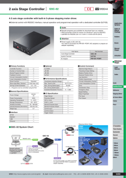


© Copyright 2026