
Milling Tools given in Annexure-I
TENDER NOTICE Advt. Ref. Number: 2014-2015/3 Date: 10-12-2014 Quotations in sealed cover are invited for the following service/items in TWO PART SYSTEM. Written request may be made for obtaining tender documents indicating tender number and item to the undersigned on or before the date specified along with required tender fee shown against the items. Tender fee will be accepted only in the form of crossed demand draft /Banker’s Cheque drawn in favour of “Accounts Officer, LABORATORY FOR ELECTRO-OPTICS SYSTEMS”, Bangalore – 560 058. SL. NO . 1 2 FILE NUMBER LEAO 2014000234 LEAO 2014000283 DESCRIPTION OF ITEM 05-AXIS CNC EQUIPMENT MILLING DESIGN & DEVELOPMENT OF WHIFFLETREE MOUNTS FOR LIGHT WEIGHT MIRROR TESTING SUPPLY & INSTALLATION OF HIGH PURITY GAS DISTRIBUTION SYSTEM DUE DATE TIM E OPENING DATE TIM E TENDE R FEE 28/01/2015 1600 HRS 29/01/2015 1100 HRS Rs.230/- 28/01/2015 1600 HRS 29/01/2015 1100 HRS Rs.230/- 28/01/2015 1600 HRS 29/01/2015 1100 HRS Rs.230/- 3 LEAO 2014000379 4 LESD 2014000380 IR INTEFERENCE FILTER 28/01/2015 1600 HRS 29/01/2015 1100 HRS Rs.230/- 5 LESD 2014000381 RATE CONTRACT FOR SPACE QUALIFIED BLACK PAINTING 28/01/2015 1600 HRS 29/01/2015 1100 HRS Rs.230/- 6 LESD 2014000382 POLARIZATION MAINTAINING SPLICER FUSION 28/01/2015 1600 HRS 29/01/2015 1100 HRS Rs.230/- 7 LEDR 2014000383 IMPLEMENTATION OF MS PROJECT SERVER 2013 28/01/2015 1600 HRS 29/01/2015 1100 HRS Rs.230/- 8 LEGN 2014000341 SUPPLY. INSTL OF TESTING OF 500 KVA DG SET 28/01/2015 1600 HRS 29/01/2015 1100 HRS Rs.230/- 9 LEAO 2014000415 FABRICATION & SUPPLY OF OPTICAL MASK BLOCKS 28/01/2015 1600 HRS 29/01/2015 1100 HRS Rs.230/- TENDER DOCUMENTS ISSUED UPTO 14:00 HRS IST ON 27/01/2015 NOTE: Tender documents are available on ISRO website www.isro.org. Interested tenderers may at their option download the tender documents from the website and submit their offers along with the prescribed tender cost in the form of Bank Draft as per details in the Tender Notification. Separate requests and Demand Draft shall be sent for each tender document. Sd/PURCHASE & STORES OFFICER for & on behalf of President of India The Purchaser 1 Request for Proposal (RFP) For Supply, Installation & Commissioning of 5 Axis CNC Milling Equipment July 2014 Laboratory for Electro-optics Systems (LEOS) Indian Space Research Organisation (ISRO) 1st Cross, 1st Stage, Peenya Industrial Area BANGALORE-560058 INDIA 2 INDEX: Sl.No 1.0 2.0 2.1 3.0 3.1 3.2 3.3 3.4 3.5 3.6 3.7 3.8 3.9 3.10 3.11 3.12 3.13 3.14 3.15 3.16 3.17 04 05 06 07 08 09 10 11 12 13 14 15 16 Description Introduction Application Application requirements in detail Detailed Specifications of Equipment Linear Axes Rotary Axes Spindle On line tool measurement system Measuring probe to take quick work offsets Mist extractor and oil mist separator Central Lubrication System Coolant Reprocessing System Coolant system for spindle motor and lead screws of axes Hand Held Unit Protection gear for operator and equipment Spindle Monitoring 3D data model of equipment configuration Automatic Tool Changer (as an option) CNC Control system Power distribution system Ultrasonic Milling Attachment (as an option) Spares & Accessories Tools, Jigs & Fixtures UPS for the equipment (as an option) Installation, Demonstration & Training Deliverables Utilities Guarantee / Warranty Quotation Format Total Quality Control & Management Delivery Period Expertise & Heritage General Terms & Conditions Format of compliance / Non compliance matrix Page No 04 04 04 06 07 08 10 11 11 12 12 12 13 13 13 14 14 14 14 16 17 18 18 19 19 20 20 21 21 22 22 22 22 23 3 Index for Figures / Drawings / Sketches: Fig.1: Pocket Milling with different type of cross sections (open back) Fig.T1: Types of Milling Tools used for pocket milling operation Fig.2: Process of Trepanning Fig.T2: Trepanning Tool Fig.3: Process of Slicing Fig.T3: Slicing Wheel Fig.4: Process of Chamber milling / making pockets with undercuts Fig.T4: Chamber milling Tool Fig.5: Process of Curve generation & Tool for curve generation (Spherical profiles) Fig.6: Process of Edging Fig.7: Process of Profiling on the bottom of pockets Fig.T7: Ball Nose Diamond Tool for profiling on bottom of pockets Fig.8: Maximum Job size and traverse requirements on Equipment Fig.9: Additional Circular Base plate on NC rotary table Fig.10: NAS Test Piece (Aluminium) Fig.11: Acceptance Trial Job (ZERODUR) Fig.12: Milling Tool Type 1 Fig.13: Milling Tool Type 2 Fig.14: Face Milling Tool Fig 15: Cup wheel for curve generation 4 1. INTRODUCTION: Laboratory for Electro-Optics Systems (LEOS) is a research and development organization working in the area of Applied Optics programmes carrying out design and development of telescope optics systems for astronomical, weather observation and forecasting applications. LEOS invites proposals for supply, installation and commissioning of 5 Axis CNC Milling Equipment together with the required accessories and spares as per the specifications, on-site demonstration of equipment performance and training on the equipment at LEOS. 2. APPLICATION: The equipment will be used for carrying out various mechanical operations such as pocket milling, trepanning, slicing, chamber milling (making undercuts), generating spherical curvatures (profiles), edging, and generating profiles on the bottom of pockets etc., on glass-ceramics such as ZERODUR & Optical glasses using diamond impregnated tools. The equipment will also be used for milling of metals such as Aluminium, Titanium, Invar etc., using carbide tools . The components produced in the equipment are used in Indian communication & weather observation satellites. 2.1. APPLICATION REQUIREMENTS IN DETAIL: For all the following given operations, range of Job sizes is: Diameter: Minimum 100mm to Maximum 1500mm Thickness: Maximum Height of Job above the machine table will be ~500mm Sl.No Process 01 Milling Application Face milling, Contour milling to generate pockets with various geometries such as circular, triangular, square, pentagonal, hexagonal and any other odd shape. Tool size / Job Size requirements For the given operations following range of milling tools are used Diameter: Minimum Maximum 100mm Length: Minimum Maximum 300mm 5mm to 20mm to Equipment should be able to produce pockets with web thickness (thickness of ribs between pockets) as small as 2mm over a depth of 200mm 02 Please refer to Fig.1 for a typical pocket milling application Trepanning Cutting of smaller size circular blanks from larger size blanks, using trepanning tools (Please refer to Fig.T1 for type of milling tools used) For the given operation following range of trepanning tools are used Diameter: Minimum 50mm to Maximum 210mm 5 Length: Minimum Maximum 300mm 03 04 05 06 Slicing Chamber milling (making pockets with undercuts) Spherical curve generation Edging 50mm to Please refer to Fig.2 for a typical trepanning application Slicing of blanks using slicing wheels (cut off wheels) (Please refer to Fig.T2 for type of trepanning tools used) For the given operation following range of slicing wheels are used Slicing wheels of size from dia 250mmX1mm thick upto dia 400mmX2mm thick Please refer to Fig.3 for a typical slicing operation Milling of pockets with under cuts. Pocket contours are as mentioned in Sl.No.1. (Please refer to Fig.T3 for type of slicing wheels used) For the given operation following range of diamond wheels along with shanks are used Equipment should be able to produce pockets with web thickness as small as 2mm over a depth of 200mm, and flange thickness as small as 2mm with an undercut as large as 15mm Diamond wheels of size from Dia25mmX5mm thick to Dia75mmX5mm thick. Size of shanks used are from Dia6mm*100mm long upto Dia20mm*300mm long Please refer to Fig.4 for a typical (Please refer to Fig.T4 for a typical chamber milling process tool with its shank for chamber machining) Generation of axi-symmetric For the given operation diamond spherical curvatures (concave / impregnated Cup-wheels (radius convex) on Jobs nose wheels) of following sizes are used: Equipment should be able to From Dia 50mm to Dia 200mm generate the profile with an (with nose radius ~2.5 to 5.0mm) accuracy of 50m with respect to nominal profile Please refer to Fig.5 for a typical curve generation operation Reducing the outer diameter of circular Jobs / increasing the inner diameter of Jobs This will be achieved either by contour milling (circular interpolation) “or” by keeping the tool stationary and rotating the Job about the axis of rotary table Equipment should be capable Please refer to Fig.T5 for a typical Cup wheel (radius nose wheel) For the given operation following range of milling tools are used Diameter: From 5mm to 100mm Length: From 20mm to 300mm 6 of producing Jobs with a roundness of <20m for a maximum diameter of 1500mm while edging 07 Please refer to Fig.6 for a typical edging process Profiling This is a process of generating on the spherical curvature (convex / bottom of concave) on the bottom of pockets pockets to achieve uniform thickness of front surface in Jobs (Please refer to Fig.T1 for type of milling tools used) Diamond Impregnated Ball nose cutters of following range of sizes are used for this application: From Dia10mmX50mm long to Dia20mmX200mm long Please refer to Fig.7 for a typical Please refer to Fig.T7 for a typical profiling process on bottom of ball nose tool for making profiles on pockets bottom of pockets 2.2 In each of the above operations, the equipment should produce components with high degree of surface finish with an average surface roughness less than or equal to 3m (300 grade emery finish) Note: For each and every process mentioned above, the vendor should clearly give the details regarding the range of diamond impregnated tools (minimum and maximum size) that is possible for usage in the offered equipment. 3.0 DETAILED SPECIFICATIONS OF THE EQUIPMENT: The Five Axis CNC Milling Equipment to be supplied should consist of: 1. 3 Linear axes (X, Y, Z) 2. 2 Rotary Axes : a) NC rotary table (C axis) rotating about vertical axis & b) Swiveling Milling head (B axis) 3. Spindle for tool rotation. All the five axes (X,Y,Z,C,B) and spindle rotation should be simultaneously programmable 4. On-line tool measurement system 5. Measuring probe for taking quick work-offsets 6. Mist extractor and Oil mist separator 7. Central lubrication system for all the axes 8. Coolant circulation and reprocessing system for Job and tool cooling 9. Coolant system for cooling of spindle motor and axis lead screws 10. Hand Held Unit 11. Protection for operator and equipment 12. Spindle Monitoring feature 13. 3D data model of equipment configuration 14. Automatic Tool Changer (to be quoted as an option) 15. CNC control system 16. Power distribution system 7 17. Ultrasonic Milling Attachment (to be quoted as an option) In addition to above, vendors can also quote for any other optional features that will improve performance of the equipment “or” improve the milling process for above materials. 3.1: Linear Axes: 3.1.1: Traverse: following are the traverse requirement for axes (Please refer to the Fig.8) In X axis (Longitudinal) ≥1550mm In Y axis (Transverse) ≥1250mm In Z axis (Vertical) ≥1000mm Minimum incremental travel required in each ≤0.001mm axis Feed drive It is desirable to have digitally controlled AC motor, directly linked with liquid cooled recirculating ball screw Feed power of axes Drives and Motors should have sufficient power to carryout the milling operations listed in section 2.1 at maximum feed rate with about 2000 kg load on table and with about 1.0mm depth of cut. Feed rate Should be variable from 0.1mm/min -30000mm/min Rapid traverse Should be ≥ 30m/min Guide ways Desirable to have Roller guide ways Position feed back Should be by direct linear path measuring systems Temperature compensation Position feed back should have temperature compensation Resolution of path measuring system Should be ≤ 0.001mm Positioning accuracy required in X axis ≤ 0.01mm for maximum traverse Positioning accuracy required in Y axis ≤ 0.01mm for maximum traverse Positioning accuracy required in Z axis ≤ 0.01mm for maximum traverse Positioning repeatability required in each axis ≤ 0.01mm Backlash error in each axis ≤ 0.005mm Perpendicularity between X & Y axes ≤ 0.02mm over 500mm traverse Perpendicularity between X & Z axes ≤ 0.02mm over 500mm traverse Perpendicularity between Y & Z axes ≤ 0.02mm over 500mm traverse *The nomenclature of axes (viz., X, Y & Z) can vary and depend upon the configuration of equipment offered. Vendor has to provide following technical details for all the linear axes, their drives and motors Type of drive Cooling mechanism for the lead screws 8 Maximum feed speed in mm/min Rapid feed speed in mm/min Maximum Feed power Type of guide ways Type of position feed back mechanism & its resolution Positioning accuracy Equipment layout diagram indicating all the axes and the clearance that is available at extreme positions of the tool with maximum size of work piece on the table. 3.2.A: NC Rotary Table (C axis) Size of the NC rotary table Rotation speed Feed rate Minimum incremental rotation Input resolution & Display resolution Positioning accuracy Backlash error Maximum load capacity Drive capacity T slots Centre bore Flatness & wobble of the clamping surface The size of NC rotary table should be such that it can hold Jobs upto Diameter 1500mm with radial clamping & with a maximum Job height of 500mm over the NC rotary table The NC rotary table should have rotational speed that can be varied from 0.1 to 10 RPM Should be variable from 36 to 3600 deg/min ≤ 0.001 deg ≤ 0.001 deg ≤ 10 arc sec ≤ 10 arc sec Should be able to carry a maximum load of 2000 kg Drive and Motor should have sufficient power to rotate the table at minimum to maximum feed rate with about 2000 kg load on it and carryout the operations listed in section 2.1 Should have sufficient number of T slots on the surface for clamping of the Jobs. The distance between T slots should be between 100 to 200mm. There should be a slot at the centre for the purpose of alignment. Should have a centre bore typically of Dia 50H7, concentric to the axis of rotary table for checking the alignment The flatness of the clamping surface should be better than 0.02mm when measured over entire area. The wobble (tilting) of clamping surface when measured on a diameter of 1000mm for one full rotation should be less than 0.02mm ** Nomenclature for NC rotary table can vary and depend upon the configuration of equipment offered. 9 Vendor has to provide following technical details for the NC rotary table quoted Diagram of the NC rotary table showing the clamping surface Number of T slots available for clamping the Job and their size Distance between the T slots Details of a centre bore for alignment Maximum torque / Holding momentum of the NC rotary table Maximum & minimum feed rate in RPM Input and display resolution Positioning accuracy in arc sec Material of construction of the NC rotary table Dimensions of the biggest work piece that can be accommodated on the rotary table in terms of Job diameter and its height from the surface of rotary table Maximum load carrying capacity of the NC rotary table 3.2.B: Swivelling of Milling Head (B Axis) Type of milling head Swivel Angle Input resolution & Display resolution Minimum incremental rotation Feed rate Positioning accuracy Drive Spindle motor The milling head should be a continuously positioning universal milling head The milling head should have a swivel range of at least 0 to 180 deg (that is, tool axis vertical position to tool axis horizontal position) with an increment of 0.001 deg. Also it should have swivel in opposite direction by at-least 10 deg. ≤ 0.001 deg ≤ 0.001 deg Minimum ≤ 0.1 RPM Maximum ≥ 20RPM ≤10 arc sec It is desirable to have a digitally controlled AC motor with appropriate cooling mechanism to drive the milling head. The spindle motor should be integrated with the milling head ** Nomenclature for swiveling milling head can vary and depend upon the configuration of equipment offered. Vendor has to provide following technical details for the B axis (swivel of milling head) quoted: Type of the drive Type of cooling mechanism for the main motor Type of mechanism for indexing Swivel momentum Holding momentum 1 Range of swivel angle Maximum Feed rate in RPM Positioning Accuracy in arc sec Repeatability at spindle nose and indexing accuracy 3.3 Spindle Type of spindle Spindle taper Speed range (RPM) Radial out of spindle Axial run out of spindle Tool clamping Tool clamping force Spindle torque Drive capacity Inner coolant system Spindle motor cooling It is preferable to have integrated spindle (with built in spindle motor) Desirable to have HSK 63A Minimum ≤ 10 RPM Maximum ≥ 8000 RPM ≤0.005mm when measured near the spindle nose using test mandrel ≤0.01mm when measured at a distance of 300mm from the spindle nose using test mandrel ≤0.005mm Should be of hydro mechanical type Tool clamping force generated should be ≥ the clamping force required to hold the tool while carrying out the operations listed out in section 2.1 while using maximum size of tools at maximum tool RPM, feed rate and depth of cut of ~ 1mm Spindle torque should be ≥ the torque exerted by the tool while carrying out the operations listed out in section 2.1 while using maximum size of tools at maximum tool RPM, feed rate and depth of cut of ~ 1mm Drive capacity should be ≥ the power required for carrying out the operations listed out in section 2.1 while using maximum size of tools at maximum tool RPM, feed rate and depth of cut of ~ 1mm Spindle should have an Internal Coolant System for passage of coolant through the tool while milling. It is desirable to have liquid cooling arrangement for spindle motor Vendor has to provide the following technical details of spindle offered Type of construction Spindle taper Diameter of spindle Make of the spindle Drive capacity 1 RPM Vs Torque chart at 40% and 100% duty cycle RPM range (Minimum to Maximum) Acceleration time & Deceleration time Tool clamping and unclamping mechanisms Spindle accuracies (radial and axial run out) Details of the spindle bearing viz., size & type of bearings and their arrangement Tool clamping force Cooling mechanism for the spindle motor Details of Internal coolant system Maximum weight of the tool and maximum size of the tool (along with tool holder) that can be held in spindle at maximum RPM Balancing quality of tools that are required for stability of spindle at maximum RPM Vendor has to provide the details of equipment configuration indicating the relative positions of linear axes with nomenclature and traverse range, relative position of rotary axes with nomenclature and range of rotation. 3.4 On-line Tool measurement system An on line tool measurement system should be provided in the equipment to measure tool length, diameter and to detect the tool breakages. Measurement cycles should be in-built in the equipment to measure the tool parameters viz., diameter and length & update them in the equipment automatically. The tool measurement system should be able to measure the sizes from dia 5mmX40mm long upto Dia 100mmX300mm long Vendor should provide all the technical details of such a measurement system offered with the equipment 3.5 Measuring probe to take quick work offsets Vendor should offer a measuring probe which can be mounted in the spindle of equipment. This probe is required to probe the Job for initial job setting and taking work offsets. Work offsets should get updated automatically in the equipment. The probe should work along with an optical machine interface (OMI) which works as a receiver. The OMI should be mounted on milling head / any other stationary part near the milling head. The probe and OMI should not have any physical connection. It is preferable to have Rensihaw make measuring probe along with OMI for this purpose. In-built measurement cycles should be provided in the control system to measure different features of Job such as Inner and outer diameters of circular Jobs Angle between different faces of Jobs Height of the Job etc., & to update them in the work offsets automatically. Vendor should provide all the technical details of such a measuring probe offered. 1 3.6 Mist Extractor and Oil Mist Separator The equipment should be provided with a mist extractor to extract the coolant mist from the working area. Provision should be there to operate this mist extractor in manual mode as well as in auto mode. The coolant mist so extracted should be passed through an oil mist separator to separate out the moisture from the mist & to let only the air out. The moisture which is separated should get collected so that it can be drained off periodically. Vendor should provide all the technical details of mist extractor and oil mist separator offered. 3.7: Central lubrication system: The equipment should have a centralized lubrication system for automatic lubrication of guide ways and lead screws of all axes at regular intervals. Provision for monitoring the lubricant level should be there. Vendor should provide the technical details of the lubrication system being offered and the details of the lubricant to be used. 3.8 Coolant circulation system for Tool & Job Cooling: - Equipment should have provision for coolant flow through the spindle center as well as a multi jet unit surrounding the milling head. It should be possible to switch from coolant to air in the multi jet unit. The flow and pressure parameters for coolant flow through the spindle and for external coolant (multi jet unit) should be displayed in equipment - Most of the time, ZERODUR and optical glass will be milled on this equipment using diamond tools. Material is removed in the form of fine powder and gets carried away with the coolant. Hence, there should be a system, to filter the coolant at different levels (coarse and fine) and to separate out the powder from coolant before it enters the coolant tank. - It is desirable to have following type of coolant circulation system in the equipment: The coolant being returned from the equipment consists of fine glass powder suspended in it. This should be collected in an intermediate settling tank from where it should be pumped to the main coolant tank as and when the level in the intermediate tank reaches a set value. This coolant should pass through a centrifuge which should have a conical shaped rotor rotating at high RPM. Coolant while passing over the rotor undergoes directional change and due to centrifugal forces, the glass powder remains in the centrifuge and coolant alone goes out. This coolant should be further filtered using a cartridge type filter to less than 20 micron level and it should be pumped back to equipment. The temperature of coolant in the main tank should always be maintained, using a chiller unit mounted on the coolant tank. 1 - Vendor should note that inspite of filtration at different levels; coolant still consists of fine glass powder which can erode the equipment parts especially near the spindle through coolant passages. Hence, the through coolant system in the spindle should be designed accordingly to avoid erosion of spindle parts. The spindle should have a very good sealing mechanism to avoid entering of coolant into the spindle bearing area. - The coolant being pumped from coolant tank to equipment should be filtered to less than 20 microns filtration level. There should be a separate pump and motor for external coolant (coolant jets around the milling head) and for coolant through the tool (through the spindle center) - The flow rate and pressure of the through coolant as well as external coolant should be monitored & displayed on operator panel. - Condition of the filters at various stages should be monitored and there should be an alarm when the soiling of filter exceeds allowable value. - The coolant tank should have a capacity of at least 500 Lts - The material of tank and its paint should be compatible for water soluble cutting fluids. Vendor should provide all the technical details of the coolant recirculation and conditioning system offered. 3.9 Cooling system for cooling spindle motor and axis lead screws: - The equipment should be equipped with a chiller unit to cool the spindle motor and axes lead screws to avoid excessive heating. -The temperature of spindle motor and axes motors should be monitored and displayed on the operator panel. Vendor should specify the technical details of cooling system offered. 3.10 Hand Held Unit: A mini hand held unit to move the linear axes and rotary axes in Jog mode should be supplied by the vendor. It should be possible to move each axis in steps of 0.001, 0.01, 0.1, 1.0mm (selectively) and also into continuous mode. There should be an emergency push button provided on the hand held unit. 3.11 Protection for operating personnel and equipment components: The working area of the equipment (NC rotary table, X,Y,Z axes, Spindle and milling head) should be fully enclosed in a cabin including the roof portion. Such a cabin should have sliding doors and large safety glass windows for observing the working area. 1 It should be possible to load the Jobs of size upto Dia 1500mm X 500mm thick using the crane directly onto the Rotary table. Safety interlocks should be provided to restrict the working of equipment in auto mode & coolant circulation while the cabin doors are open. The guide-ways of the axes should be covered suitably to avoid the coolant from entering into the guide-ways. 3.12: Spindle Monitoring: There should be a provision for monitoring the condition of the spindle by sensing the vibration at spindle and in the case of vibration exceeding the set limits, equipment should be stopped. There should be a provision to monitor the condition of spindle bearing. There should be a provision to monitor the torque on the spindle and in case of the torque exceeding the set limits, milling process should be stopped. 3.13: 3D data model of equipment configuration Vendor should supply the 3D data model of the equipment configuration. The data model should mainly include equipment bed, milling head, working table, linear and rotary axes and cabin. This data model should be supplied in a format that is compatible with CAM softwares such as DELCAM. It will be integrated with CAM software and will be used for off-line simulation of 5 axis milling programs in CAM software, before actual execution in the equipment. 3.14 Automatic Tool Changer (as an optional item) Vendor can quote for automatic tool changer as an option. There should be at-least 30 slots in the in the tool magazine. It is preferred to have a vertical chain magazine. Program controlled tool change in the spindle should be possible Vendor should provide all the details pertaining to Automatic Tool Changer offered including the maximum no of tools that can be stored, maximum size of tools that can be loaded in the magazine etc., 3.15 CNC control system: The 5 Axis CNC milling equipment should consist of a PLC based CNC system, preferably latest SIEMENS CNC control system through which all the operations of the equipment , its power management & distribution, monitoring of different process parameters & their control, monitoring of equipment safety & their control is carried out. 1 Hardware of CNC path control system Operator panel Multi programming Number of controlled axes Data Memory Programming Programming Tools Simulation Editing of programs Over rides Operating modes Should be a micro processor based CNC path control system with integrated PLC and digital drive technology Should be a flat operating panel with display size of ≥ 19”. Screen texts should be in English. Screen saver feature should be available. It should be possible to carryout programming, editing and simulation during the operation of equipment. All the 5 axes (X, Y, Z, B,& C) and spindle should be simultaneously programmable Should have a hard disk of memory at least 40GB to store the machine data Programming with DIN and ISO formats should be possible. Should be compatible for programming with mathematical operators and functions Should be compatible for programming in Cartesian and Polar coordinates Program input and optimization through keys, simultaneous with milling should be available. Clear arrangement of keys on operator panel with provision for panel lockout should be there. Basic cycles for drilling, milling, basic geometries should be built in Graphic simulation of milling process should be there with determination of program execution time. 3D representation of milling process should be there, with facility to zoom in and out and view the sections Editing of program by copying, insert, exchanging and deletion of program blocks, program jumps should be possible The following over rides should be available - Feed rate over ride 0 – 120% - Rapid traverse over ride 0 – 120% - Spindle speed override 0 – 120% The following operating modes should be available - Jog mode - MDI mode - Auto mode - Single block mode - Teach in mode (interactive program 1 Safety Interlocks Display of Error messages Program Transfer to equipment Storage of part programs and tool data Look ahead function Tool data monitoring generation together with machine) Suitable interlocks should be provided for avoiding over-travel of any axis Suitable safety interlocks should be provided to safe guard the equipment and for safety of operating personal as per international safety standards and protocols Safety alarms should be provided for emergency situations Error messages due to faults should be displayed and logged The following modes of transferring program to equipment should be available - Ethernet interface - USB interface - RS232 Should be able to store at least 500 part programs and data of 500 tools in the memory The control should check the directional changes in advance during execution of program and adjust feed speed to adapt to the dynamics of equipment Tool length, radius and wear compensation features should be available 3.16: Power distribution system: 3.16.1 The equipment must be compatible for the following power supply 400V, 3 Phase, Neutral, Earthing, 50 Hz 230V, 1 Phase, Neutral, Earthing, 50 Hz Maximum Variation in the supply voltage ~ ±10% Maximum Variation in the supply frequency ~ ± 2 Hz 3.16.2. The power distribution bus should have all the necessary hardware such as fuses, relays and circuit breakers to safeguard the various sub-systems and the equipment as a whole, against any power fluctuations, power hazards and any such situations which may arise during the use of the equipment as per the applicable standards and norms 3.16.3 Compressed Air purity should be specified by Vendor. Coarse filtration will be done by LEOS. However, the equipment should have mechanism for fine filtration of compressed air. 3.16.4. There should be a stop push button to stop CNC equipment in case of emergency 3.16.5. There should be a dedicated AC unit for electrical control cabinet 1 3.16.6. Vendor should provide technical data on the safety features available in the equipment that is offered. 3.17: ULTRASONIC Milling Attachment (as an OPTIONAL ITEM) Vendor should quote as an option, Ultrasonic milling attachment for the milling equipment being offered: The ultrasonic milling attachment offered, should conform to following specifications: 3.17.1 Principle of operation: The milling tool should be oscillated at a frequency of 16 to 30 KHz with amplitude of 20-50 microns on the cutting edge and simultaneously it should be rotated with speeds upto 8000RPM. The simultaneous rotation at high RPM and oscillation of tool at ultrasonic frequency should result in milling of hard and brittle materials. 3.17.2 Application: Using the ultrasonic milling feature the equipment should be able to carryout all the milling processes mentioned in section 2.1 on hard and brittle materials like sintered silicon carbide, Zerodur and optical glass. Also, using this feature, equipment should be able to produce thin sections (typically ribs of size 2mm thickX100mm width X 200mm deep) in Zerodur and optical glass without inducing significant stress. 3.17.3 Hardware & Software for ultrasonic milling attachment: Equipment should have necessary ultrasonic generator to generate ultrasonic signal from frequency of 16 to 30 KHz and to transmit the signal from generator to the rotating tool on milling head. Equipment should have necessary software to fine tune and optimize the ultrasonic frequency for every particular tool. Software should have necessary feature to start and stop ultrasonic milling by simple commands in the program. Software should have provision to monitor and control the actual ultrasonic power being utilized by the tool during milling process. The equipment should also be operable in conventional mode without ultrasonic milling, without calling for any changes in the milling head. The tool holders and tools that are offered for ultrasonic milling should work in conventional milling mode also. 3.17.4 Performance of Ultrasonic Milling Attachment: Vendor should clearly mention the advantages of ultrasonic milling of ZERODUR over conventional milling. Vendor should also mention the difference between milling parameters viz., infeed and feed rate while milling Zerodur with and without ultrasonic milling feature, especially when milling deep pockets, for Eg. Circular pocket of Dia80X200mm deep. Vendor should clearly mention how the ultrasonic milling feature offered with the machine helps in - improvement in material removal rates, - improvement in surface finish, - increase in tool life, - reduction in cutting forces Sufficient data should be provided in support of the above. 1 Comparison data for any typical ZERODUR job for milling with and without ultrasonic feature also should be provided. Vendor also should mention approximate reduction in milling time that can be achieved by using the ultrasonic milling feature when compared to conventional milling process especially while milling deep pockets of ~200mm depth. If ordered, the performance of the equipment with ultrasonic milling feature should be demonstrated by milling a trial Job on Sintered silicon carbide and Zerodur as per the given drawing by using ultrasonic milling feature. Vendor should provide sufficient technical data and information regarding the ultrasonic milling attachment offered. 4.0 : SPARES & ACCESSORIES: Along with the equipment, vendor should provide spares that are essential for 1000 days of trouble free operation of equipment (@ 8 hours per day). Typically these spares should include (but not limited to) Items which are required for regular preventive maintenance like pneumatic, hydraulic and coolant filters, LM guide way wipers, filter mats for the AC units etc., Consumables like central lubrication grease/oil, hydraulic oil, chiller solutions, lubricating sprays for spindles and ATC chains Electrical spares like contactors, fuses, relays, MCBs, switches etc., Spares that are specific to the equipment offered and which can cause complete break down of equipment in case of non availability In addition to the above, one standard maintenance kit for the equipment offered should be provided along with the equipment Vendor has to provide information on Spares / Service support facilities available in India for the equipment offered. Information on the strength of sales / service team and their locations in India should be provided In addition to above, vendor may also suggest spares that have to be maintained by LEOS for trouble free operating of equipment. Vendor should provide a list of all such spares along with the offer 5.0 : TOOLS, JIGS & FIXTURES: Vendor has to provide the following along with the equipment: 1. Vendor has to quote for the following tools, jigs and fixtures in the slabs of 5, 10 & 15 Nos for each item - Diamond Milling Tools, Cup wheels & Facing Tools for milling of zerodur. Size of Milling Tools ranging from Dia8mm*40mm Long upto Dia28mm*220mm Long, Facing Tools from Dia50mm upto Dia100mm, Cup wheels from Dia75mm upto Dia150mm 1 - HSK 63A tool holders with ER25 taper along with the locking nut, spanner and with a provision for inner coolant passage ER25 collets of bore diameter from 8mm upto 16mm HSK63A tool holder with 20H7 shaft with a provision for inner coolant passage HSK63A tool holder of Hydrogrip type with a provision for inner coolant passage Sleeves for the Hydrogrip tool holders for holding the tools from Dia 8mm upto 16mm A list of the diamond tools, tool holders, collets and sleeves are given in the Annexure-I. Vendor should submit quote for the diamond tools, tool holders, collets and sleeves that are given in the Annexure-I. Quantity of the items will be finalized at the time of ordering of the equipment. LEOS can either order all the items mentioned in the annexure or only part of them. Diamond Tools & Tools holders quoted should be compatible for ultrasonic milling also. 2. Slip gauges (from 25mm upto 100mm thickness) to set the tool heights 3. Fixture for fixing the tools in the tool holder, off-line 4. Vendor has to quote, as an optional item, a circular base plate of Dia 1600mm as per the Fig.9. This base plate, if ordered, should be fixed on the NC rotary table and supplied along with the equipment. The details of base plate are given in Annexure-II 5. Vendor has to explicitly specify the list of any other tools, jigs and fixtures that are required for day to day operation of the equipment 6. UPS FOR THE EQUIPMENT (as an OPTIONAL ITEM): Vendor should quote as an option, an Online Uninterruptible power supply system (UPS) which meets the power requirement of the equipment with a back up time of 30min. The UPS, if ordered should be supplied along with the equipment. Installation of UPS and its commissioning and performance demonstration is the scope of vendor. 7. INSTALLATION, DEMONSTRATION & TRAINING: 7.1. Vendor has to demonstrate the performance of equipment and its accessories at vendor’s site as per mutually agreed test / evaluation protocol 7.2. Vendor has to install and commission the equipment and its accessories at LEOS and demonstrate it’s performance as per mutually agreed test / evaluation protocol 7.3. The following protocol shall be adopted to test & evaluate the equipment, and for its acceptance at vendors site as well as at LEOS. 1. Demonstration of equipment accuracies by milling a Aluminium NAS test piece as per the Fig.10, with work piece located at center of table and at extreme position of the table 2. Demonstration of zerodur milling using diamond impregnated tools by milling a Zerodur blank as per the drawing (Fig.11) enclosed. Demonstration should be carried out by Ultrasonic Milling, if the ultrasonic milling attachment is ordered with the equipment. 2 7.4. All the tools, jigs & fixtures that are required to carry out above trials and demonstrations should be arranged by the vendor. Aluminium Raw material for making NAS test piece also should be arranged by the vendor. ZERODUR material for acceptance trials as per Fig.11 will be provided by LEOS. After the completion of trials, all the tools, jigs and fixtures used shall be handed over to LEOS. 7.5. Vendor has to offer training to LEOS personnel at both at Vendor’s site as well as at LEOS on operation and maintenance of the equipment and its accessories. 8. DELIVERABLES: Vendor should consider the following as the deliverables: 1. Five Axis CNC Milling Equipment together with all the accessories 2. Tools, Jigs and fixtures, power cables & any other items that are required for installation, commissioning and conducting acceptance trials of the equipment on NAS Test Piece as well as on ZERODUR part, as mentioned in section 7.0 3. Tools, Tool Holders, Collets, Sleeves and other accessories as mentioned in section 5.0 4. Spares and accessories for 1000 days of operation of equipment (@ 8 hours per day), as mentioned in section 4.0 5. All the technical documents (in English) for Installation, Operation, Maintenance and Servicing of equipment and a soft copy of the same in the form of DVD 6. Electrical, Pneumatic & Hydraulic circuit diagrams and mechanical drawings of critical sub assemblies (in English) and a soft copy of the same in the form of DVD 7. Manual for electrical, mechanical, hydraulic & pneumatic spare parts and a soft copy of the same in the form of DVD 8. Certificate of compliance conforming to the specifications of the equipment 9. Accuracies test chart for the delivered equipment passed by QA of the vendor 10. Reports of Factory acceptance test (FAT) and site acceptance test (SAT) 11. Manuals of the all the OEM equipment used in milling equipment (in English) 12. Soft copy of PLC program / Machine data 13. On-line UPS system (Optional), if ordered, which meets power requirements of equipment with 30min backup time & its manuals in English 14. A circular base plate of Dia1600mm (Optional), if ordered, fitted to the NC rotary table 15. Ultrasonic Milling Attachment (Optional), if ordered. 16. Automatic Tool Changer (Optional), if ordered. 9. UTILITIES: - The vendor has to provide information on on-site infrastructure viz., Electricity connection, compressed air, water supply, floor space required, special foundation required, if any, that is to be made available for installation & commissioning of equipment. 2 - Vendor should also provide information on the weight of equipment, height of the building required for installing it, clearance space required all around the equipment and any special preparation of the site required in their technical offer. 10. GUARANTEE / WARRANTY: 1. Vendor is required to provide warranty on the CNC milling equipment and all its accessories for a minimum period of one year from the date of acceptance. 2. Vendor also has to quote separately for extended warranty of 2 years from the date of expiry of normal warranty/guarantee 3. Vendor has to explicitly provide the terms and conditions of the warranty / guarantee offered. The nature of maintenance / service work that will be provided during warranty period should be clearly mentioned. 4. Vendor has to provide information on nature of preventive maintenance that has to be carried out periodically for smooth operation of equipment. 11. FORMAT OF QUOTATION: Vendor has to submit the offer in two parts, namely “TECHNICAL BID” & “COMMERCIAL BID” in two separate sealed covers. On the covers it should be mentioned as “TECHNICAL BID” or “COMMERCIAL BID”. Both the sealed covers should be enclosed in another sealed cover and should be submitted to purchase department of LEOS. 1. Technical bid should consist of the following: Detailed technical specifications of the equipment offered, including all its accessories, compliance / non-compliance matrix with respect the specifications in the tender along with the justification for compliance / non-compliance, Technical data sheets & theoretical calculations made in support of the offer made by vendor. Vendor is required to prepare & provide a technical compliance / non-compliance matrix against each specification in the tender, supported by technical data sheets and justifications with high lights ( a sample compliance/non compliance matrix is enclosed) 2. Commercial bid should consist of the following: - Prices of the 5 Axis CNC Milling Equipment and its accessories - Quotation for the Optional Items - Quotation for the tools, tool holders and their accessories - Quotation for the spares and accessories those are required for trouble free running of equipment for at least 1000 hours of operation (@ 8 hours operation per day) - Quotation for conducting factory acceptance test (FAT) & Training of LEOS personnel at vendor’s site - Quotation for Installation & Commissioning of Equipment along with its accessories and optional items at LEOS. - Quotation for extended warranty of 2 years. 2 - Quotation for Annual Maintenance Service Contract of the equipment after the expiry of warranty period. Terms of such a maintenance contract shall be provided clearly. - All the commercial terms and conditions, warranty / guarantee clauses, validity of the offer etc., 12. TOTAL QUALITY CONTROL & MANAGEMENT: 1. Vendor has to provide the management structure for execution of the present contract, identifying the focal point 2. Vendor is required to provide the Quality Policy of the organization and the plan for Total Quality Management (TQM) 13. DELIVERY PERIOD: 1. The desirable delivery period shall be 10 months from the date of release of Purchase order 14. EXPERTISE & HERITAGE: 1. Vendor has to provide information on the company’s expertise in building 5 Axis CNC Milling Equipment, particularly for the model offered. 2. Vendor has to provide information on the company’s heritage in supplying similar equipment for milling ZERODUR & Optical Glass along with user’s feedback. 3. Vendor has to provide the bench mark of performance of the equipment in relation to other suppliers with respect to the equipment offered 4. Vendor has to provide information on company’s profile covering various aspects viz., technical, commercial and the uniqueness of the organization in the specific sphere of building and supplying CNC Milling Equipment 5. Vendor has to provide information of the status of their organization in India in terms of manufacturing locations, sales, service and spares support details etc., 6. Vendor has to provide the references of earlier supplies made globally for zerodur milling and particularly for the model of equipment offered. 15. GENERAL TERMS & CONDITIONS: - It is mandatory for the vendor to provide the ‘Technical Compliance Matrix’ with proper technical justification with documentary evidences and technical data sheets. Simple duplication of the technical specifications (without support documents and technical explanation) will lead to the rejection of the offer. - All bids must be enclosed with firm commitments and approvals from regulatory authorities (respective countries) to supply the equipments if the order is placed. 2 Format of “Compliance / Non Compliance Matrix” to be submitted by the Vendors Sl.No Section in RFP LEOS Offer Complied specification given by with data sheets Vendor LEOS / Spec/ catalogues Not / complied calculations with LEOS spec 1 2.1 2.1.1 2.1.2 2.1.3……….upto 2 2.1.7 3.1.1 3.1.2 3.1.3….. and so so an forth upto section 14 Remarks Supporting LIST OF DIAMOND TOOLS TO BE QUOTED ALONG WITH THE MILLING EQUIPMENT A MILLING TOOL TYPE 1 Wall thickness Diameter Milling Grain Milling of cutting near Depth Size Sl. Tool cutting Edge No Type edge Do(mm) MD (mm) WT(mm) Type of Tool Provision for Holder with Type of Concent Applicatio internal which tool Bonding ration n coolant should be passage compatible for HSK63A with machining ER25 taper ZERODUR 1 MT1 8 40 1.5 D151 Metallic C75 Yes 2 MT1 8 80 1.5 -DO- -DO- -DO- -DO- -DO- -DO- 3 MT1 10 50 1.5 -DO- -DO- -DO- -DO- -DO- -DO- 4 MT1 10 100 1.5 -DO- -DO- -DO- -DO- -DO- -DO- 5 MT1 12 60 1.5 -DO- -DO- -DO- -DO- -DO- -DO- 6 MT1 12 110 1.5 -DO- -DO- -DO- -DO- -DO- -DO- 7 MT1 14 60 1.8 -DO- -DO- -DO- -DO- -DO- -DO- 8 MT1 14 110 1.8 -DO- -DO- -DO- -DO- -DO- -DO- 9 MT1 14 160 1.8 -DO- -DO- -DO- -DO- -DO- -DO- 10 MT1 16 60 1.8 -DO- -DO- -DO- -DO- -DO- -DO- 11 MT1 16 110 1.8 -DO- -DO- -DO- -DO- -DO- -DO- 12 MT1 16 180 1.8 -DO- -DO- -DO- -DO- -DO- -DO- 13 MT1 18 60 2.0 -DO- -DO- -DO- -DO- -DO- -DO- 14 MT1 18 110 2.0 -DO- -DO- -DO- -DO- -DO- -DO- 15 MT1 18 180 2.0 -DO- -DO- -DO- -DO- -DO- -DO- 16 MT1 20 60 2.0 -DO- -DO- -DO- -DO- -DO- -DO- 17 MT1 20 110 2.0 -DO- -DO- -DO- -DO- -DO- -DO- 18 MT1 20 180 2.0 -DO- -DO- -DO- -DO- -DO- -DO- 19 MT1 24 60 2.0 -DO- -DO- -DO- -DO- -DO- -DO- 20 MT1 24 110 2.0 -DO- -DO- -DO- -DO- -DO- -DO- 21 MT1 24 180 2.0 -DO- -DO- -DO- -DO- -DO- -DO- 22 MT1 28 60 2.0 -DO- -DO- -DO- -DO- -DO- -DO- 23 MT1 28 110 2.0 -DO- -DO- -DO- -DO- -DO- -DO- 24 MT1 28 180 2.0 -DO- -DO- -DO- -DO- -DO- -DO- B MILLING TOOL TYPE2 Wall thickness Diameter Total Grain Milling of cutting Length of near Size Sl. Tool cutting Edge Tool No Type edge WT(mm) Do(mm) L(mm) Type of Tool Provision for Holder with tolerance Type of Concent Applicatio internal which tool on dia of Bonding ration n coolant should be tool shank passage compatible for HSK63A with machining ER25 taper ZERODUR 1 MT2 8 100 1.5 D151 Metallic C75 Yes h6 2 MT2 8 125 1.5 -DO- -DO- -DO- -DO- -DO- -DO- h6 3 MT2 10 100 1.5 -DO- -DO- -DO- -DO- -DO- -DO- h6 4 MT2 10 125 1.5 -DO- -DO- -DO- -DO- -DO- -DO- h6 5 MT2 12 100 1.5 -DO- -DO- -DO- -DO- -DO- -DO- h6 6 MT2 12 140 1.5 -DO- -DO- -DO- -DO- -DO- -DO- h6 7 MT2 14 100 1.8 -DO- -DO- -DO- -DO- -DO- -DO- h6 8 MT2 14 150 1.8 -DO- -DO- -DO- -DO- -DO- -DO- h6 9 MT2 14 200 1.8 -DO- -DO- -DO- -DO- -DO- -DO- h6 10 MT2 16 100 1.8 -DO- -DO- -DO- -DO- -DO- -DO- h6 11 MT2 16 150 1.8 -DO- -DO- -DO- -DO- -DO- -DO- h6 12 MT2 16 220 1.8 -DO- -DO- -DO- -DO- -DO- -DO- h6 13 MT2 18 100 2.0 -DO- -DO- -DO- -DO- -DO- -DO- h6 14 MT2 18 150 2.0 -DO- -DO- -DO- -DO- -DO- -DO- h6 15 MT2 18 220 2.0 -DO- -DO- -DO- -DO- -DO- -DO- h6 16 MT2 20 100 2.0 -DO- -DO- -DO- -DO- -DO- -DO- h6 17 MT2 20 150 2.0 -DO- -DO- -DO- -DO- -DO- -DO- h6 18 MT2 20 220 2.0 -DO- -DO- -DO- -DO- -DO- -DO- h6 19 MT2 24 100 2.0 -DO- -DO- -DO- -DO- -DO- -DO- h6 20 MT2 24 150 2.0 -DO- -DO- -DO- -DO- -DO- -DO- h6 21 MT2 24 220 2.0 -DO- -DO- -DO- -DO- -DO- -DO- h6 22 MT2 28 100 2.0 -DO- -DO- -DO- -DO- -DO- -DO- h6 23 MT2 28 150 2.0 -DO- -DO- -DO- -DO- -DO- -DO- h6 24 MT2 28 220 2.0 -DO- -DO- -DO- -DO- -DO- -DO- h6 C Tool Sl.No type FACING TOOL Type of Tool Wall Provision for Diameter Total Holder with thickness Type of Applicatio internal of cutting Length of Concentrationwhich tool near Grain SizeBonding n coolant Edge Tool should be cutting passage compatible edge 1 2 3 FT FT FT D L(mm) WT(mm) 50 100 150 75 75 75 2 2 2 D151 -DO-DO- Metallic -DO-DO- C75 -DO-DO- HSK63A with20h7 shaft -DO-DO- for machining ZERODUR -DO-DO- Yes -DO-DO- CUP WHEEL Tool Sl.No Type 1 2 3 Do(mm) CW CW CW Type of Tool Provision for Diameter Total Holder with Type of Applicatio internal of cutting Length of Radius ofGrain Size Concentrationwhich tool Bonding n coolant Edge Tool should be cutting passage compatible edge WT(mm) Do(mm) L(mm) HSK63A for with20h7 machining shaft ZERODUR 80 75 2.5 D151 Metallic C75 Yes 130 75 2.5 -DO-DO-DO-DO-DO-DO160 75 2.5 -DO-DO-DO-DO-DO-DO- LIST OF TOOL HOLDERS TO BE QUOTED ALONG WITH THE MILLING EQUIPMENT Sl.No Tool Holder Type 1 HSK63A Tool Holder with ER25 TAPER 2 HSK63A Tool Holder with 20h7 SHAFT 3 ER25 collets - 7-8mm, 9-10mm, 11-12mm, 13-14mm, 15-16mm 4 Hydrogrip tool holder with HSK63A taper 5 Sleeves for Hydrogrip tool holder - 8mm, 10mm, 12mm, 14mm, 16mm Fig.1: Pocket Milling Diamond Wheel Tool Shank Pocket Milling Tools Face milling Tool Fig T1: Types of Milling Tools used for pocket milling and face milling application FIG 2: Trepanning Trepanning Tool FIG T2: Trepanning Tool Smaller dia blank cut from larger size Job Job Job Mounting pads Machine Table Fig T3: Slicing Wheel Fig 3:Slicing Job Machine Table Slicing wheel Fig.T4 Chamber Milling Tool Fig.4 Chamber Milling Fig 6: Edging Fig T1: Types of Milling Tools used for edging Fig 7: PROFILING ON BOTTOM OF POCKETS T7: Ball Nose Diamond Tool to generate profile on the bottom of pockets Fig.8: Maximum Job size and traverse requirements M12 *60mm Helicoils Pitch=30mm From PCD 120mm TO 1500mm Material: AL6061 Surface Treatment: To be anodized Planarity < 50 microns when measured over entire surface Fig.11: Acceptance Trial Job Milling Tools given in Annexure-I Fig.12:Milling Tool Type1 Diamond (abrasive) portion ER25Taper Milling Tools given in Annexure-I Fig.13: Milling Tool Type2 Fig.14: Face milling Tool Milling Tools given in Annexure-I Milling Tools given in Annexure-I Fig.15: Cup wheel NOTE: 1. Tender documents are available on ISRO Website www.isro.org Interested tenderers may, at their option download the tender documents from the website and submit their offers along with the prescribed tender cost in the form of Bank Draft as per details in the Tender Notification. 2. Tender documents also can be obtained against the above Tender Notice, from Purchase Officer, Laboratory for electro-optics systems, 1 st stage, 1st cross, Peenya Industrial Estate, Bangalore – 560 058, India on payment of non-refundable tender fee as indicated above, on all working days between 9.00 Hrs to 16.00Hrs. 3. Tender fee shall be payable only in the form bank draft drawn in favour of Accounts Officer, LEOS, payable at Bangalore. No other mode of payment for tender fee is acceptable. 4. DD should not be dated prior to the date of advertisement / from the date of website. Separate requests and demand drafts shall be sent for each tender document. 5. Vendors/firms name and tender No. shall be indicated on the reverse side of the Demand Draft. 6. While requesting for tender documents, please do not Superscribe tender number and due date on the envelope. 7. Detailed specifications, terms and conditions are furnished in the tender documents. 8. LEOS will not be responsible for non-receipt of tender documents/offers due to postal delay/loss in transit. 9. Quotations received without payment of tender fee will be treated as unsolicited. 10. Indian agents while quoting on behalf of their principals are requested to provide necessary authorization letter from their principals. 11. The offer should be valid for the period of ninety days from the date of opening. 12. Quotations received after the due date and time will not be considered. 13. While submitting your offer please Superscribe tender No. and due date on the envelope. 14. If tender opening date happens to be a public holiday tender will be opened on the next working day. 15. No request for the extension of the due date will be considered. 16. Purchase Officer, LEOS reserves the right to accept or reject any tenders in part or full without assigning any reasons thereof. sd/S. SUBRAMANYA PURCHASE & STORES OFFICER for & on behalf of President of India The Purchaser REQUEST FOR PROPOSAL NO. LEAO 2014 000 234 01 DUE ON 28h January ,2014 SPECIAL INSTRUCTIONS FOR TWO (2) PART TENDER We invite your offer duly signed, consisting in Two (2) Part envelopes marked as follows: a) PART – I TECHNICAL & COMMERCIAL TERMS (in duplicate) b) PART - II PRICES (in duplicate) 1.0 PART-I TECHNICAL & COMMERCIAL 1.1 1.2 1.3 1.4 Our Tender Enquiry contains technical requirements and specification of “ 5 Axis CNC Milling Machine” The detailed technical specification of offer should be covered in this part. The Part-I should not contain prices. Please enclose Compliance Statement for all the specifications (point by point) is to be prepared and duly signed. Our standard terms and conditions listed at Enclosure-I. You shall confirm compliance to all points of Enclosure-I. In addition, you shall also confirm compliance to the points listed in Annexure-I. The Terms and conditions shall form part of the contract. The compliance statement for commercial terms and conditions duly signed shall be sent with Part-I of the envelope in duplicate. Also enclose a copy of the details indicated in price quote (WITHOUT PRICE OR BY MASKING THE PRICE) mainly to know the items/description for which you have indicated prices in the price bid. THIS PART SHOULD NOT CONTAIN ANY PRICE DETAILS. THIS PART SHOULD BE KEPT IN SEPARATE COVER SUPERSCRIBED AS UNDER:- Quotation against Tender No. LEAO 2014 000 234 01 Due on 28th January ,2014at 16:00 Hours (IST) FOR THE “ 5 Axis CNC Milling Machine” PART I - TECHNICAL & COMMERCIAL 2.0 PART II – PRICE BID 2.1 The prices for the items shall be indicated item wise in this part. All the items mentioned in the Technical Part shall be mentioned here and prices indicated against each. The break-up for each item of supply or service shall be indicated. Wherever options are quoted, the same shall also be indicated with quantity and unit rate separately. The prices are to be mentioned both in figures and words. The prices shall be valid for a minimum period of 180 days. This part shall also be kept in a separate sealed cover superscribing as follows: Quotation against Tender No. LEAO 2014 000 234 01 Due on 28th January ,2014 at 16:00 Hours (IST) FOR THE 2.2 2.3 “ 5 Axis CNC Milling Machine” 3.0 PART II – PRICE BID THE TWO SEALED COVERS PROPOSED AS ABOVE SHOULD BE KEPT IN ANOTHER ENVELOPE, SEALED AND SUPERSCRIBED AS UNDER:Quotation against Tender No. LEAO 2014 000 234 01 Due on 28th January ,2014 at 16:00 Hours (IST) FOR THE “ 5 Axis CNC Milling Machine” Containing TWO SEPARATE COVERS PART I & PART II. ADDRESSED TO: PURCHASE & STORES OFFICER LABORATORY FOR ELECTRO OPTICS SYSTEMS GOVERNMENT OF INDIA DEPARTMENT OF SPACE 1ST STAGE, 1ST CROSS, PEENYA INDUSTRIAL ESTATE BANGALORE – 560 058, INDIA PHONE +91-80-2839 8836 FAX +91-80-2839 1964 Email: [email protected] 3.1 The cover should indicate “ From” address GENERAL 1. Normally we do not open PART-II, if PART-I does not meet with our technical specification / requirements. Your offer prepared as above should reach us on or before the due date and time i.e. 28th January 2014 AT 16:00 HOURS (IST). The offers received after the due date and time will be treated as invalid. 2. We would request you to send us an advance intimation on the dispatch particulars of your bid, by fax or by email as soon as possible. 3. In case you do not wish to participate in the bid, we would appreciate your returning the tender enquiry to us with a regret letter. IMPORTANT : “QUOTATIONS RECEIVED BY EMAIL / FAX WILL BE TREATED AS INVALID” - X- ANNEXURE – I Tender No: LEAO 2014 000 234 01 Due on 28th January ,2014 at 16.00 Hrs. [IST] LABORATORY FOR ELECTRO OPTICS SYSTEMS BANGALORE The following specific articles shall form part of LEOS Contract in addition to the Standard Terms and Conditions: Sl.No 1 2 3 4 5 6 7 8 9 10 11 Article Delivery Terms Prices shall be quoted on C & F Bangalore basis or Ex-works or FOB, FCA etc., Department will choose any one of them. Currency in which prices are quoted Delivery Period Firm delivery period shall be quoted Payment Terms a) Sight Draft through State Bank of India, I phase, Peenya Industrial Estate, Bangalore: 560058. INDIA for foreign vendor. b) 100% Payment within 30 days after receipt & acceptance of Stores for Indian Suppliers. Bank Charges Vendor shall bear all bank charges outside India Warranty Vendor shall give minimum Twenty Four (24) months warranty from the date of commissioning and acceptance OR as per enclosure Performance Guarantee Vendor shall provide Performance Bank Guarantee for 10% of the Contract Price for satisfactory performance of the items supplied during Warranty period. Indian Agent Name & Address of Indian Agent. LEOS will not pay any Agency Commission Liquidated Damages for late supply. Vendor is liable to pay liquidated damages at 0.5% per week for delay in supply, subject to a maximum of 10% of the Contract Price. Transit Insurance Vendor shall insure the item from Warehouse (Seller) to Warehouse (Purchaser) at his cost. Law Applicable: Indian Law Bidders Confirmation Sl.No ARTICLE 12 Bidders Confirmation INSTALLATION:a) Please specify who will undertake installation of the system at LEOS, Bangalore, India. b) The price quoted are inclusive of Installation charges. 13 14 INCOME TAX: Acceptance for recovery of Income tax, if applicable, as per Indian Income Tax rules, on services viz.: installation etc. AMC [i] Vendor shall undertake the Annual Maintenance of the system after Completion of Warranty. The AMC charges shall be as follows: (a) Comprehensive. (including spares) (b) Non-Comprehensive. (without spares) (c) Per call basis. [ii] The AMC charges shall be valid for a Period of 3 years after Warranty. 15 16 17 Place: Date: SUPPLY OF SPARES/SERVICES. Vendor shall provide uninterrupted supply of spares/services for a minimum period of 10 years after Warranty. VALIDITY The quote / prices shall be valid for a period of 180 days from the date of Tender opening. Price Bid Masking : Whether copy of Price Bid after Masking the prices has been enclosed in the Technical Bid Authorized Signatory Company Seal INSTRUCTIONS TO TENDERERS AND GENERAL TERMS AND CONDITIONS OF PURCHASE 1. Instructions to Tenderers: 1. The Tenderers should submit quotations in duplicate in a sealed envelope, superscribing the Tender No. & due date of opening and complete in all respects with technical specifications including pamphlets & catalogues. 2. A Proforma Invoice may also be given which should contain the following information (a) The FOB value, the C&F value for import by Sea-freight/Air freight upto and for air parcel post upto Bangalore-58 should be separately indicated. (b) Agency Commission: LEOS will not pay any Agency Commission. (c) The Contractor shall Invoice only for the nett amount payable to him after deducting the amount of Agency Commission included in the Invoice which would be paid to the Indian Agents directly by the Purchaser. However, the Contractor’s Invoice should separately reflect the amount of commission payable to his Indian Agent. (d) The earliest delivery period and country of origin of the Stores. (e) Banker’s name and address of the contractor. (f) The approximate nett and gross weight and dimensions of the packages/cases. (g) Recommended spares for satisfactory operation for a minimum period of one year. (h) Details of any technical service, if required for erection, assembly, commissioning and demonstration. 3. The FOB & C&F prices quoted should be inclusive of all taxes, levies, duties arising in the tenderer’s country. 4. The offer should be valid for a minimum period of 120 days from the due date of opening of the tender. 5. Samples, if called for, should be sent Free of all charges. 6. Late tenders will not be considered. Quotations by cable must be followed by detailed offers, to reach within 15 days. 7. Offers made by Indian Agents on behalf of their principals, should be supported by the Proforma Invoice of their principals. 8. The details of Import License will be furnished in the Purchase Order. 9. The authority of person signing the tender, if called for, shall be produced. 10. Instruction/Operation manual containing all assembly details including wiring diagrams should be sent wherever necessary in duplicate. All documents/correspondence should be in English language only. 11. The purchaser reserves the right to accept or reject the lowest or any other offer in whole or in part without assigning any reason. 12. It is expressly agreed that the acceptance of the stores contracted for is subject to final approval in writing by the Purchaser. 13. (a) Part shipment is not allowed unless specifically agreed to by us. (b) As far as possible stores should be dispatched by Indian Flagged vessels/Air India or through any Agency nominated by us. 14. Inspection/Test Certificate should be provided for the goods after testing it thoroughly at the Contractor’s works if any inspection by Lloyds or any other testing agency is considered necessary, it shall be arranged by contractors. 15. Where erection or assembly or commissioning is a part of the contract it should be done immediately on notification. The contractor shall be responsible for any loss/damages sustained due to delay in fulfilling this responsibility. 16. For items having shelf life, those with maximum shelf life should be supplied, if order is placed. 1. Terms & Conditions: 1. Definitions: (a) (b) (c) (d) The term ‘Purchaser’ shall mean the President of India or his successors or assigns. The term ‘Contractor’ shall mean, the person, firm or company with whom or with which the Order for the supply of stores is placed and shall be deemed to include the Contractor’s Successors, representatives, heirs, executors and administrators unless excluded by the contract. The term ‘Purchase Order’ shall mean, the communication signed on behalf of the Purchaser by an officer duly authorized intimating the acceptance on behalf of the Purchaser on the terms & conditions mentioned or referred to in the said communication accepting the Tender or offer of the Contractor for supply of Stores or plant machinery or part thereof. The term ‘Stores’ shall mean, what the Contractor agrees to supply under the contract as specified in the Purchase Order. 2. Prices: Tenders offering firm prices will be preferred. Where a price variation Clause is insisted upon by a tenderer, quotations with a reasonable ceiling should be submitted. Such offers should invariably be supported by the base price taken into account at the time of tendering & also the formula for any such variations. 3. Terms of Payment: 3.1 3.2 Being a Department of Government of India, the normal terms of payment are by Sight Draft. However, other terms of payment like establishment of Letter of Credit may be considered by the Purchaser on such terms and conditions as may be agreed upon. The Sight Draft/Letter of Credit will be operative on presentation of the under mentioned documents :(a) (b) (c) (d) (e) (f) (g) Original Bill of Lading/Airway Bill. Commercially certified Invoices describing the stores delivered, quantity, unit rate and their total value in triplicate. The Invoice should indicate the discounts, if any, and Agency Commission separately. Packing List showing individual dimensions and weight of packages. Country of Origin Certificate in duplicate. Test Certificate Declaration by the Seller that the contents in each case are not less than those entered in the Invoice & the quality of the Stores are guaranteed as per the specifications asked for by the Purchaser. Warranty & Guarantee Certificates vide Clause 20. 4. Import License: Reference to Import License No. and date and contract number and date shall be prominently indicated in all the documents vide para 3.2. 5. Demurrage: Supplier shall bear demurrage charges if any incurred by the Purchaser due to delayed presentation of shipping documents as prescribed in Para 3.2. to the Bankers within reasonable time (say within 10-12 days) from the date of bill of lading for sea consignments and within ¾ days from the date of Air Way Bill for Air consignments. 6. Address of the Indian Agents: --------------------------------------------------------------------------------------------------------------------------------------------------------7. Guaranteed Time of Delivery: The time for and the date of delivery stipulated in the Purchase Order shall be deemed to be the essence of the Contract, Delivery must be completed within the dates specified therein. 8. Inspection and Acceptance test: 8.1 The Purchaser’s representatives shall also be entitled at all reasonable times during manufacture to inspect, examine & test on the Contractor’s premises the material & workmanship of all Stores to be supplied under this Contract & if part of the said Stores is being manufactured on other premises, the Contractor shall obtain for the Purchaser’s representative permission to Inspect examine & test as if the equipment were being manufactured on the Contractor’s premises. Such Inspection, examination & testing shall not release the contractor from the obligations under this contract. 8.2 For tests on the premises of the Contractor or any of his sub contractors, the Contractor shall provide free of cost assistance labour, materials, electricity, fuel and instruments as may be required or as may be reasonably needed by the Purchaser’s representative to carry out the tests efficiently. 8.3 When the Stores have passed the specified test, the Purchaser’s representative shall furnish a certificate to this effect in writing to the Contractor. The Contractor shall provide copies of the tests Certificates to the Purchaser as may be required. 9. Mode of dispatch: Generally, Stores should be dispatched by Indian Flagged Vessel/Air India or through any other Agency nominated by the Purchaser. A copy of the Invoice and packing list should invariably be kept inside each of the package. 10. Port of Entry: Chennai/Bangalore 11. Port of Consignee: Stores Officer, LEOS/ISRO, Bangalore . 12. Ultimate Consignee: Stores Officer, LEOS/ISRO Bangalore (INDIA). 13. Shipping Marks: The marks on the shipping documents such as Invoice, bill of lading and on the packages should be as follows :- ------------------------------------------------------------------------------------------------------------------------------------------------------------------------------PURCHASE ORDER NO…………………… ………………… GOVERNMENT OF INDIA Department of Space Laboratory for Electro-Optics Systems 1st Stage, 1st Cross, Peenya Industrial Estate Bangalore-560 058 Date Destination…………………………… ……………….. Port of Entry -----------------------------------------------------------------------------------------------------------------------------------------------------------------------------14. Insurance of the Stores: The Purchaser shall be responsible for insuring the Stores wherever considered necessary. The Contractor, shall however be responsible for notifying as per proforma enclosed to the Purchaser or the insurers nominated by the Purchaser. The complete details of the proposed shipments including the value of each shipment and other relevant data, immediately after shipment to enable the Purchaser or the insurers to arrange for the insurance of the insurance policy, if required. The necessity or otherwise of insurance will be as indicated in the Purchase Order. 15. Contractor’s default liability: 15.1 The purchaser may upon written notice of default to the Contractor terminate the Contract in whole or in part in circumstances detailed hereunder. (a) If in the judgement of the Purchaser the Contractor fails to made delivery of Stores within the time specified in the Contract Agreement or within the period for which extension has been granted by the Purchaser to the Contractor. If in the judgement of the Purchaser the Contractor fails to comply with any of the other provisions of this contract (b) 15.2 15.3 15.4 In the event of Purchaser terminates the contract in whole or in part as provided in Clause 15.1 the purchaser reserves the right to Purchase upon such terms and in such a manner as he may deem appropriate Stores similar to that terminated and the Contractor shall be liable to the Purchaser for any additional cost for such similar stores and/or liquidated damages for delay as defined in Clause 19 until such reasonable times as may be required for the final supply of Stores. If this contract is terminated as provided in Clause 15.1 the Purchaser in addition to any other rights provided in this Article, may require the Contractor to transfer title & deliver to the Purchaser under any of the following cases in the manner & as directed by the Purchaser. (a) Any completed Stores (b) Such partially completed Stores, drawing, information & Contract rights (hereinafter called manufacturing material) as the Contractor has specifically produced or acquired for the performance of the contract as terminated, The Purchaser shall pay to the Contractor the Contract price for completed Stores delivered to & accepted by the Purchaser & for manufacturing materials delivered and accepted. In the event the Purchaser does not terminate the Contract as provided in Clause 15.1 the Contractor shall continue the performance of the Contract, in which case he shall be liable to the Purchaser for liquidated damages for delay as set out in Clause 19 until the Stores are accepted. 16. Replacement: If the Stores or any portion thereof is damaged or lost during transit, the Purchaser shall give notice to the Contractor setting forth particulars of such stores damaged or lost during transit. The replacement of such Stores shall be effected by the Contractor within a reasonable time to avoid unnecessary delay in the intended usage of the Stores. The price of replacement items shall be paid by the Purchaser on the basis of original price quoted in the tender or as reasonably worked out from the tender. The cost of damages will however be claimed by the Purchaser from the insurance company. The import License/Customs Clearance Permit for the replacement will be provided by the Purchaser. 17. Rejection: In the event that any of the Stores supplied by the Contractor is found defective in material or workmanship otherwise not in conformity with the requirements of the Contract specifications, the Purchaser shall either reject the Stores or request the Contractor, in writing to rectify the same. The Contractor on receipt of such notification shall either rectify or replace the defective Stores free of cost to the Purchaser. If the Contractor fails to do so, the Purchaser may at his option either :(a) replace or rectify such defective Stores & recover the extra cost so involved from the Contractor or (b) terminate the Contract for default as provided under Clause 15 above. (c) Acquire the defective Stores at a reduced price considered equitable under the circumstances. The provision of this article shall not prejudice the Purchaser’s rights under Clause 19. 18. Extension of Time: If the completion of supply of stores is delayed due to reason of Force Majeure such as acts of God, acts of public enemy, acts of Government, fires, floods, epidemics, quarantine, restrictions, strikes and freight embargoes, the Contractor shall give notice within 15 days to the Purchaser in writing of his claim for an extension of time. The Purchaser no receipt of such notice after verification, if necessary may agree to extend the Contract delivery date as may be reasonable but without prejudice to other terms and conditions of the contract. 19. Delay in Completion/ liquidated Damages: If the Contractor fails to deliver the Stores within the time specified in the Contract or any extension thereof, of Purchaser shall recover from the Contractor as liquidated damages a sum of one half of one percent (0. 5 percent) of the Contract price for each calender week of delay. The total liquidated damages shall not exceed ten percent (10 percent) of the contract price. Stores will be deemed to have been delivered only when all its component parts are also delivered if certain components are not delivered in time, the Stores will be considered as delayed until such time as the missing parts are delivered. 20. Guarantee & Replacement: (a) The Contractor shall guarantee that the stores supplied shall comply fully with the specifications laid down, for material, workmanship and performance. (b) For a period of twelve months after the acceptance of the stores, if any defects are discovered therein or any defects therein are found to have developed under proper use arising from faulty materials, design or workmanship contractor shall remedy such defects at his own cost provided he is called upon to do so within a period of 14 months from the date of acceptance thereof by the Purchaser who shall state in writing in what respect the stores or any part thereof are faulty. If in the opinion of the Purchaser, it becomes necessary to replace or renew any defective stores such replacement or renewal shall be made by the Contractor free of all costs to the Purchaser provided the notice informing the contractor of the defect is given by the purchaser in this regard within the said period of 14 months from the date of acceptance thereof. Should the Contractor fail to rectify the defects, the Purchaser shall have the right to reject or repair or replace at the cost of the Contractor the whole or any portion of the defective stores. The decision of the Purchaser, not withstanding any prior approval or acceptance or inspection thereof on behalf of the Purchaser, as to whether or not the Stores supplied by the contractor are defective or any defect have developed within the said period of 12 months or as to whether the nature of the defects requires renewal or replacement shall be final, conclusive and binding on the contractor. To fulfill guarantee conditions outlined in Clause 20 (a) above, the Contractor shall, at the option of the purchaser, furnish a Bank guarantee (as prescribed by the Purchaser-Bank Guarantee enclosed) from a Bank approved by the Purchaser for an amount equivalent to 10% of the value of contract along with first shipment documents. On the performance & completion of the Contract in all respects, the Bank Guarantee will be returned to the Contractor without any interest. All the replacement stores shall also be guaranteed for a period of 12 months from the date of arrival of Stores at Purchaser’s site. Even while the 12 month guarantee applies to all Stores in case where a greater period is called forth by our specifications then such a specification shall apply; in such cases the period of 14 months referred to in Clause 20(b) and (c) shall be the ‘asked for’ guarantee period plus two months. (c) (d) (e) (f) (g) (h) 21. Requirement of additional numbers of the Stores/Spare parts ordered: The Contractor shall also undertake the supply of additional number (Nos) of items covered by the Order as considered necessary by the Purchaser at a later date. The actual price to be paid shall be mutually agreed to after negotiations. 22. Packing: (a) The Contractor wherever applicable shall pack & crate all Stores for sea/air shipment as applicable in a manner suitable for export to a tropical humid climate in accordance with internationally accepted export practices and in such a member so as to protect it from damage & deterioration in transit by road, rail or sea for space qualified stores. The contractor shall be held responsible for all damages due to improper packing. (b) The Contractor shall ensure that each box/unit of shipment is legible and properly marked for correct identification. The failure to comply with this requirement shall make the contractor liable for additional expenses involved (c) The Contractor shall notify the Purchaser of the date of shipment from the port of embarkation as well as the expected date of arrival of such shipment at the designated port of arrival. (d) The Contractor shall give complete shipment information concerning the weight, size, content of each packages etc. (e) Transshipment of equipment shall not be permitted except with written permission of the Purchaser. (f) Apart from the dispatch documents negotiated through Bank, the following documents shall also be airmailed to the Purchaser within 7 days from the date of shipment by sea & within 3 days in case of air consignments. (a) Commercial Bill of Lading/Air Way Bill/Post Parcel Receipt (two non-negotiable copies.) (b) Invoice (3 copies) (c) Packing List (3 copies) (d) Test Certificate (3 copies) (e) Certificate of Origin. Contractor shall also ensure that one copy of the packing list is enclosed in each case. 23. Arbitration: If at any time any question, disputes or differences whatsoever shall arise between the Purchaser and the Contractor upon or in connection with this contract, either party may forthwith give to the other notices in writing of the existence of such question, dispute or difference & the same shall be referred to the adjudication of two arbitrators, one to be nominated by Purchaser, other by a Contractor and in the event of any difference of opinion, the arbitrators will refer the matter to the umpire. The arbitration shall be conducted in accordance with the rules & procedure for arbitration of the International Chamber of Commerce at Paris. The expenses of the arbitrators and umpire shall be paid as may be determined by them, However, the venue of such arbitration should be in India. 24. Language and measures: All documents pertaining to the contract including specifications schedule notices, correspondence, operating & maintenance instructions drawings or any other writings shall be written in English language. The metric system of measurement shall be used exclusively in this contract. 25. Indemnity: The Contractor shall warrant and be deemed to have warranted that all Stores supplied against this contract are free and clean of Infringement of any Patent copy right or trademark and shall at all times indemnify the Purchaser against all claims which may be made in respect of the Stores for infringement of any right protected by Patent Registration of design or Trade Mark and shall take all risk of accidents or damage which may cause a failure of the supply from whatever cause arising and the entire responsibility for the sufficiency of all the means used by him for the fulfillment of the contract. 26. Counter Terms & Conditions of Suppliers: 26.1 Where counter terms and conditions/printed or cyclostyled conditions have been offered by the supplier, the same shall no be deemed to have been accepted by the Purchaser, unless specific written acceptance thereof is obtained. 26.2 Tender documents can be obtained from ISRO website also. In case a tenderer is using the documents and forms from the website, the cost of tender documents can be sent to the addressee (in the form of Bank draft) along with quotations”. 27. Security interest: On each item to be delivered under this contract, including an item of work in progress in respect of which payment have been made in accordance with the terms of the contract. Purchaser shall have a security interest in such item which shall be deemed to be released only at the time when the applicable deliverable item is finally accepted and delivered to the Purchaser in accordance with the terms of the contract. Such security interest of the Purchaser shall constitute a prior charges as against any other charge of interest created in respect of such items by any other entity. 28. Bank Charges: While the Purchaser shall bear the bank charges payable to his Bankers (State Bank of India, Peenya Branch, Industrial Estate Peenya, Bangalore – 560 058) the Contractor shall bear the Bank charges payable to his Bankers including the charges towards advising amendment commissions. 29. Training: The Contractor shall, if required by the Purchaser, provide facilities for the practical training of Purchaser’s engineering or technical personnel from India and for their active association on the manufacturing processes throughout the manufacturing period of the contract/stores number of such personnel to be mutually agreed upon. 30. Applicable Law: The Contract shall be interpreted, construed and governed by the laws of India. LABORATORY FOR ELECTRO-OPTICS SYSTEMS PURCHASE SECTION TENDER ENQUIRY NO: LEAO 2014000234 01 DATE: IMPORTANT NOTE 1. THE LAST DATE FOR SUBMISSION OF YOUR OFFER IS WITHIN 16.00 Hrs. OF 28-01-2015. 2. TENDER OPENING DATE : 29-01-2015 AT 11.00 Hrs. 3. IN CASE YOU ARE UNABLE TO QUOTE, PLEASE SEND REGRET LETTER TO [email protected]. 4. INDIAN AGENTS SHALL NOT REPRESENT MORE THAN ONE PRINCIPAL WHILE SUBMITTING THEIR OFFER. WHEREVER WE RECEIVE OFFERS OF ONE INDIAN AGENT REPRESENTING TWO DIFFERENT PRINCIPALS, BOTH THE OFFERS ARE LIABLE TO BE REJECTED. 5. PLEASE FURNISH YOUR PAN/TIN/TAN /SERVICE TAX REGISTRATION NO. ETC WHILE QUOTING. 6. EXCISE DUTY : WE ARE EXEMPTED FROM PAYMENT OF EXCISE DUTY VIDE GOVERNMENT NOTIFICATION NO. 10/97 DT. 01.03.1997 FOR WHICH NECESSARY EXEMPTION CERTIFICATE WILL BE FURNISHED FOR THE SUCCESSFUL TENDERERS 7. WE ARE EXEMPTED FROM THE PAYMENT OF CUSTOMS DUTY VIDE CUSTOMS NOTIFICATION NO. 12/2012 CUSTOMS SL. NO. 449. 8. YOUR QUOTE SHOULD BE VALID FOR 180 DAYS. 9. PURCHASE PREFERENCE/PRICE PREFERENCE WILL BE GIVEN TO PSU/SSI UNITS AS PER THE EXISTING RULES OF THE GOVERNMENT. 10. THE EVALUATION OF THE TENDER WILL NOT BE BASED ON CONDITIONAL DISCOUNT. IF ANY CONDITIONAL DISCOUNTS ARE COATED BY THE PARTY, THE QUOTE WILL NOT BE CONSIDERED. (S.SUBRAMANYA) PURCHASE & STORES OFFICER.
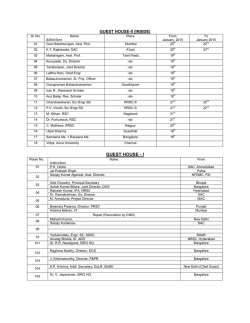
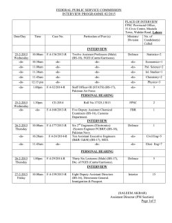
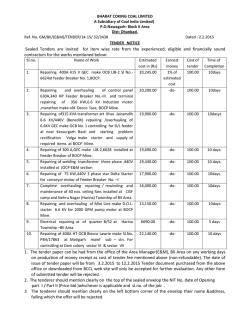
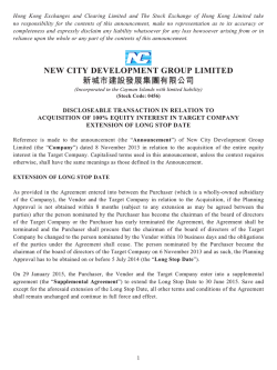
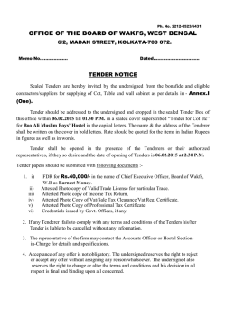
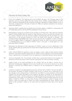

© Copyright 2026