
Adhesive Anchors - Powers Fasteners
PRODUCT INFORMATION
Adhesive Anchors
Adhesive anchoring systems offer many advantages for applications requiring high load capacities.
Capsule type systems first appeared in the market in the late 1970's followed by the early co-axial
type injection systems. Originally, these products were used in highway and bridge construction as a
substitute for grouted anchors because of speed of installation. As industry realized the benefits of
adhesive systems, their use in other building applications have gained general acceptance. Major
features applicable to adhesive systems include the ability to be used with a variety of steel element
materials, a small hole diameter compared to traditional grouting methods, no mechanical
expansion forces exerted into the base material and a sealed anchor hole for weather resistance.
SECTION CONTENTS
Typical two-part adhesive systems include an encapsulated glass design or plastic cartridge injection
systems in various configurations. Adhesive anchors typically use an ester based resin or an epoxy to
bond threaded steel rod or reinforcing bars into the anchor hole. Normally, the hole size is only
slightly greater than the rod or bar diameter. The adhesive anchor bonds threaded rods, bolts, and
reinforcing bars to the base material using cementitious materials or chemical adhesives. Loads are
transferred to the base material by the bond formed between both the anchor and the walls of the
drilled hole. Anchors of this type can have the highest load capacities because the base material
does not have to withstand the high point load stresses often associated with typical mechanical
anchors. Performance when subjected to dynamic or shock loads is typically superior.
T308+® ..................................... 275
Selection Guide.........................242
Injection Adhesives
AC100+ Gold® ...........................243
PE1000+® ................................. 258
Glass Capsules
Chem-Stud® .............................. 288
Hammer-Capsule® .................... 302
Adhesive anchors achieve their load capacities based on the ability of the adhesive used to bond to
the base material. This ability to bond, often referred to as “wetting action”, will vary depending
upon the adhesive and base material conditions. While the adhesive bonds to the base material, it
also forms a mechanical interlock around the rod or bar. I n order to form this interlock, it is
important to use clean anchor steel which have some type of deformation. Examples would be
threaded rod or deformed reinforcing bars. I n addition to the ability to bond to the base material,
the strength of the anchor steel used can be a critical factor.
Powers USA: (800) 524-3244 or (914) 235-6300
Canada: (905) 673-7295 or (514) 631-4216
www.powers.com
241
Selection Guide
Internally Threaded
Inserts
(special order)
Stainless Steel Screen
Tubes
Plastic Screen Tubes
■
□
□
■
■
■
■
■
□
■
■
■
■
■
Chisel Point Anchor
Rod
■
■
Straight Cut Anchor
Rod
■
Hammer-Capsule
■
Chem-Stud
Base Material
□
275
288
302
-
-
■
□
□
■
■
■
■
□
□
□
■
□
□
■
□
■
□
■
□
■
□
■
□
■
■
■
■
■
■
■
■
■
□
■
■
■
■
■
■
■
■
■
■
■
□
□
■
■
■
■
■
Grout-filled Concrete Masonry
Hollow Concrete Masonry
Solid Brick
Hollow Brick
Stone
Structural Clay Tile
1/4"
3/8" (#3)
Anchor Diameter ( Rebar Size )
□
258
Unreinforced Masonry (URM)
1/2" (#4)
5/8" (#5)
3/4" (#6)
7/8" (#7)
1" (#8)
(#9)
1-1/4" (#10)
1-3/8" (#11)
1-1/2" (#12)
Installation
Installed
Anchor
Chemistry
Temperature Hole Condition
Element
-
243
Lightweight Concrete
Max. Service
Temperature
-
Page
Concrete
Legend
-
Product
Hollow Core Plank
242
Anchor Hardware
T308+
■
Glass Capsule
Adhesive Anchors
PE1000+
Suitable
□
Injection Adhesive Anchors
AC100+ Gold
May be Suitable
Anchor Category
PRODUCT INFORMATION
■
■
■
■
■
■
■
■
□
□
□
□
■
■
■
■
■
■
■
■
□
□
■
■
■
□
■
□
□
□
■
■
■
■
■
□
□
□
■
■
■
■
■
■
■
■
□
□
□
□
□
■
■
■
■
■
■
Zinc Plated Carbon Steel
Stainless Steel
■
Epoxy
Vinylester
Dry
Water Saturated (Wet)
Water-filled hole (flooded)
Base Material
■
■
■
■
■
■
■
□
■
■
■
■
■
□
□
■
■
■
■
■
■
■
□
■
■
□
■
■
□
14-104°F 41-104°F 50-104°F
-10-40°C 5-40°C 10-40°C
Adhesive
32-95°F
0-35°C
41-104°F
5-40°C
65-95°F
18-35°C
Short-Term
176°F
80°C
162°F
72°C
162°F
72°C
Long-Term
122°F
50°C
110°F
43°C
110°F
43°C
www.powers.com
□
□
Canada: (905) 673-7295 or (514) 631-4216
Powers USA: (800) 524-3244 or (914) 235-6300
PRODUCT INFORMATION
AC100+ Gold
AC100+ Gold®
®
Vinylester Injection Adhesive Anchoring System
SECTION CONTENTS
PRODUCT DESCRIPTION
The AC100+ Gold is a two-component vinylester adhesive anchoring system. The system
includes injection adhesive in plastic cartridges, mixing nozzles, dispensing tools and hole
cleaning equipment. The AC100+ Gold is designed for bonding threaded rod and
reinforcing bar elements into drilled holes in concrete and masonry base materials.
GENERAL APPLICATIONS AND USES
General Information
Installation Specifications
Installation Instructions
Solid Base Materials
Hollow Base Materials
Reference Tables for Install
Bonding threaded rod and reinforcing bar into hardened concrete and masonry
Evaluated for use in dry and water-saturated concrete including water filled holes
Suitable to resist structural loads in uncracked concrete base materials for cases where anchor
design theory and criteria applies
Can be installed in a wide range of base material temperatures
SD Performance Data
SD Factored Design Strength
ASD Performance Data
Masonry Performance Data
Ordering Information
FEATURES AND BENEFITS
• Designed for use with threaded rod and reinforcing bar hardware elements
• Consistent performance in low and high strength concrete (2,500 to 8,500 psi)
• Evaluated and recognized for a range of embedments and for interior and exterior applications
• Versatile low odor formula with quick cure time
• Mixing nozzles proportion adhesive and provide simple delivery method into drilled holes
• Cartridge design allows for multiple uses using extra mixing nozzles
AC100+ Gold coaxial cartridge
with mixing nozzle
TESTING AND EVALUATION
+ Tested and evaluated by an accredited independent laboratory in accordance with ICC-ES
AC308 criteria and ASTM E 1512 for anchoring in uncracked concrete, including but not
limited to the following:
+ Reliability testing for freeze/thaw conditions
+ Reliability testing for sensitivity to hole cleaning, mixing effort and installation direction
+ Reliability testing for sustained loads, i.e. creep resistance
(see applicable long-term and short-term temperature ranges)
+ Service condition testing at decreased and elevated temperatures
+ Service condition testing in low and high strength concrete
+ Service condition testing for resistance to alkalinity and sulfur exposure
PACKAGING
APPROVALS AND LISTINGS
8 fl. oz. (235 ml or 14.3 in3)
12 fl. oz. (345 ml or 21.0 in3)
28 fl. oz. (825 ml or 50.3 in3)
International Code Council, Evaluation Service (ICC-ES) ESR-2582
Code compliant with the 2006 IBC, 2006 IRC, 2003 IBC, 2003 IRC, 2000 IBC, 2000 IRC, 1997 UBC
Tested in accordance with ICC-ES AC308 for use in structural concrete and design with ACI 318
Appendix D (Strength Design) and as amended by provisions of ICC-ES AC308 Annex A,
Section 3.3 (www.icc-es.org)
Compliant with NSF/ANSI Standard 61 for drinking water system components – health effects;
minimum requirements for materials in contact with potable water and water treatment
Conforms to requirements of ASTM C 881, Types I, II, IV and V, Grade 3, Classes A & B
(meets Type III with exception of elongation)
Department of Transportation listings – see www.powers.com or contact transportation agency
AC100+ Gold dual cartridge
with mixing nozzle and extension
Coaxial Cartridge
5 fl. oz. (150 ml or 9.2 in3)
10 fl. oz. (280 ml or 17.1 in3)
Dual (side-by-side) Cartridge
STORAGE LIFE & CONDITIONS
Fifteen months in a dry, dark environment
with temperature ranging from 32oF and
86oF (-0oC to 30oC)
ANCHOR SIZE RANGE (TYP.)
3/8" to 1-1/4" diameter threaded rod
No. 3 to No.10 reinforcing bar (rebar)
SUITABLE BASE MATERIALS
GUIDE SPECIFICATIONS
CSI Divisions: 03151-Concrete Anchoring, 04081 Masonry
Anchorage and 05090-Metal Fastenings.
Adhesive anchoring system shall be AC100+ Gold as supplied by
Powers Fasteners, Inc., Brewster, NY. Anchors shall be installed in
accordance with published instructions and requirements of the
Authority Having Jurisdiction.
Powers USA: (800) 524-3244 or (914) 235-6300
This Product Available In
Normal-weight concrete
Grouted concrete masonry (CMU)
Hollow concrete masonry (CMU)
Brick masonry
Powers Design Assist
Real Time Anchor Design Software
www.powersdesignassist.com
Canada: (905) 673-7295 or (514) 631-4216
www.powers.com
243
AC100+ Gold®
PRODUCT INFORMATION
INSTALLATION SPECIFICATIONS
Installation Specifications for Threaded Rod and Reinforcing Bar (Solid Concrete Base Materials)
Nominal Anchor Size
Notation Units
Dimension/Property
Threaded rod
-
-
3/8’’
1/2”
5/8”
3/4’’
7/8”
1”
-
1-1/4”
-
Reinforcing bar
-
-
#3
#4
#5
#6
#7
#8
#9
-
#10
Nominal anchor diameter
d
in.
(mm)
0.375
(9.5)
0.500
(12.7)
0.625
(15.9)
0.750
(19.1)
0.875
(22.2)
1.000
(25.4)
1.125
(28.6)
1.250
(31.8)
1.250
(31.8)
Nominal diameter of drilled hole
do,(dbit)
in.
7/16
ANSI
9/16
ANSI
11/16
or 3/4
ANSI
7/8
ANSI
1
ANSI
1-1/8
ANSI
1-3/8
ANSI
1-3/8
ANSI
1-1/2
ANSI
Minimum embedment1
hef,min
in.
(mm)
2-3/8
(61)
2-3/4
(70)
3-1/8
(79)
3-1/2
(89)
3-1/2
(89)
4
(102)
4-1/2
(114)
5
(127)
5
(127)
Maximum embedment1
hef,max
in.
(mm)
4-1/2
(114)
6
(153)
7-1/2
(191)
9
(229)
10-1/2
(267)
12
(305)
13-1/2
(343)
15
(381)
15
(381)
Minimum concrete member thickness1
hmin
in.
(mm)
Minimum spacing distance1,2
smin
in.
(mm)
1-7/8
(48)
2-1/2
(64)
3-1/8
(80)
3-3/4
(95)
4-3/8
(111)
5
(127)
5-5/8
(143)
6-1/4
(159)
6-1/4
(159)
Minimum edge distance1
cmin
in.
(mm)
1-3/4
(44)
1-3/4
(44)
1-3/4
(44)
1-3/4
(44)
1-3/4
(44)
1-3/4
(44)
2-3/4
(70)
2-3/4
(70)
2-3/4
(70))
A307 Grade C or F1554
Maximum torque2 carbon steel rod
(only possible
after full cure time F593 Condition CW stainless
steel rod or ASTM A193,
of adhesive)
Grade B7 carbon steel rod
Tmax
ft.-lb.
(N-m)
10
(13)
25
(34)
50
(68)
90
(122)
125
(169)
165
(224)
-
280
(379)
-
Tmax
ft.-lb.
(N-m)
16
(22)
33
(45)
60
(81)
105
(142)
125
(169)
165
(224)
-
280
(379)
-
hef + 1-1/4
(hef + 30)
hef + 2do
1. For use with the design provisions of ACI 318 Appendix D and ICC-ES AC308 Annex A, Section 3.3 and ESR-2582.
2. For installations between the minimum edge distance and 5 anchor diameters, the tabulated maximum torque must be reduced (multiplied) by a factor of 0.45.
Installation Specifications for Threaded Rod (Hollow Base Material)
Dimentions/property
Notation
Nominal Size
1/2”
3/8”
Units
Nominal threaded rod diameter
d
in
(mm)
0.375
(9.5)
0.500
(12.7)
Nominal plastic or stainless steel tube dia.
-
in.
3/8
1/2
do , (dbit )
in
1/2
ANSI
5/8
ANSI
Tmax
ft.-lb.
(N-m)
10
(8)
10
(8)
Nominal diameter of drilled hole
Maximum torque (only possible after
full cure time of adhesive)
Detail of Steel Hardware Elements
used with Injection Adhesive System
Threaded Rod
or Rebar
do,dbit
Threaded Rod and Deformed Reinforcing Bar Material Properties
Steel
Description
(General)
Steel
Specification
(ASTM)
Nominal
Anchor Size
(inch)
Minimum
Yield Strength,
fy (ksi)
Minimum
Ultimate
Strength,
fu (ksi)
Carbon rod
A 36 or F1554
Grade 36
3/8 through 1-1/4
36.0
58.0
Stainless rod
(Alloy 304 / 316)
F 593,
Condition CW
3/8 through 5/8
65.0
100.0
3/4 through 1-1/4
45.0
85.0
High strength
carbon rod
A 193,
Grade B7
A 615, A 706,
A 767, or A 996
3/8 through 1-1/4
105.0
3/8 through 1-1/4
(#3 through #10)
60.0
90.0
3/8 through 3/4
(#3 through #6)
40.0
60.0
Grade 60
reinforcing bar
Grade 40
reinforcing bar
244
www.powers.com
A 615 or A 767
Canada: (905) 673-7295 or (514) 631-4216
125.0
Powers USA: (800) 524-3244 or (914) 235-6300
PRODUCT INFORMATION
AC100+ Gold®
INSTALLATION INSTRUCTIONS (SOLID BASE MATERIAL)
DRILLING
1- Drill a hole into the base material with a rotary hammer drill tool to the size and embedment required
by the selected steel anchor element (see installation specifications for threaded rod and reinforcing bar in solid concrete base
material). The tolerances of the carbide drill bit should meet the requirements of ANSI Standard B212.15.
Precaution: Wear suitable eye and skin protection. Avoid inhalation of dusts during drilling and/or removal.
Note! After drilling and prior to hole cleaning, all standing water in the drilled bore hole must be removed if present (e.g.
vacuum, compressed air, etc.)
HOLE CLEANING
➛ BLOW 4x, BRUSH 4x, BLOW 4x
2a - Starting from the bottom or back of the anchor hole, blow the hole clean using a compressed air nozzle (min. 90 psi) or a hand
pump (supplied by Powers Fasteners) a minimum of four times (4x).
• Use a compressed air nozzle (min. 90 psi) or a hand pump (min. volume 25 fl. oz.) for anchor rod 3/8" to 3/4" diameter or
reinforcing bar (rebar) sizes #3 to #6.
• Use a compressed air nozzle (min. 90 psi) for anchor rod 7/8" to 1-1/4" diameter and rebar sizes #7 to #10. A hand pump
shall not be used with these anchor sizes.
2b - Determine wire brush diameter (see hole cleaning equipment selection table) and attach the brush with adaptor to a
rotary drill tool or battery screwgun. Brush the hole with the selected wire brush a minimum of four times (4x). A brush
extension (supplied by Powers Fasteners, Cat. #08282) should be used for holes drilled deeper than the listed brush length.
The wire brush diameter should be checked periodically during use. The brush must be replaced if it becomes worn (less than
Dmin, see hole cleaning equipment selection table) or does not come into contact with the sides of the drilled hole.
2c - Finally, blow the hole clean again a minimum of four times (4x).
• Use a compressed air nozzle (min. 90 psi) or a hand pump (min. volume 25 fl. oz.) for anchor rod 3/8" to 3/4" diameter or
reinforcing bar (rebar) sizes #3 to #6.
• Use a compressed air nozzle (min. 90 psi) for anchor rod 7/8" to 1-1/4" diameter and rebar sizes #7 to #10. A hand pump
shall not be used with these anchor sizes.
When finished the hole should be clean and free of dust, debris, ice, grease, oil or other foreign material.
PREPARING
3- Check adhesive expiration date on cartridge label. Do not use expired product. Review Material Safety Data Sheet (MSDS) before use.
Cartridge temperature must be between 32°F - 95°F (0°C - 35°C) when in use. Review gel (working) and cure time table. Consideration
should be given to the reduced gel time of the adhesive in warm temperatures.
Attach a supplied mixing nozzle to the cartridge. Do not modify the mixer in any way and make sure the mixing element is inside
the nozzle. Load the cartridge into the correct dispensing tool.
Note: Always use a new mixing nozzle with new cartridges of adhesive and also for all work interruptions exceeding the published
working time of the adhesive.
4- Prior to inserting the anchor rod or rebar into the filled bore hole, the position of the embedment depth has to be marked on the anchor.
Verify anchor element is straight and free of surface damage.
5- Adhesive must be properly mixed to achieve published properties. Prior to dispensing adhesive into the drilled hole, separately
dispense at least three full strokes of adhesive through the mixing nozzle until the adhesive is a consistent gray color. Do not attach a
used nozzle when changing to a new cartridge.
Review and note the published working and cure times (see gel time and curing time table) prior to injection of the mixed adhesive
into the cleaned anchor hole.
(Continued on next page)
Powers USA: (800) 524-3244 or (914) 235-6300
Canada: (905) 673-7295 or (514) 631-4216
www.powers.com
245
AC100+ Gold®
PRODUCT INFORMATION
INSTALLATION INSTRUCTIONS (SOLID BASE MATERIAL)
INSTALLATION
6- Fill the cleaned hole approximately two-thirds full with mixed adhesive starting from the bottom or back of the anchor
hole. Slowly withdraw the mixing nozzle as the hole fills to avoid creating air pockets or voids. For embedment depth greater
than 7-1/2” an extension nozzle (3/8” dia.) must be used with the mixing nozzle.
With Piston Plug:
Piston plugs (see adhesive piston plug table) must be used with and attached to mixing nozzle and extension tube for
horizontal and overhead installations with anchor rod from 3/4" to 1-1/4" diameter and rebar sizes #6 to #10. Insert piston
plug to the back of the drilled hole and inject as described in the method above. During installation the piston plug will be
naturally extruded from the drilled hole by the adhesive pressure.
Attention! Do not install anchors overhead without proper training and installation hardware provided by Powers Fasteners.
Contact Powers for details prior to use.
7- The anchor should be free of dirt, grease, oil or other foreign material. Push clean threaded rod or reinforcing bar into the
anchor hole while turning slightly to ensure positive distribution of the adhesive until the embedment depth is reached.
Observe the gel (working) time.
8- Be sure that the anchor is fully seated at the bottom of the hole and that some adhesive has flowed from the hole and all
around the top of the anchor. If there is not enough adhesive in the hole, the installation must be repeated. The anchor shall not
be moved after placement and during cure.
CURING AND LOADING
9- Allow the adhesive anchor to cure to the specified full curing time prior to applying any load (see gel time and curing time table).
Do not disturb, torque or load the anchor until it is fully cured.
10- After full curing of the adhesive anchor, a fixture can be installed to the anchor and tightened up to the maximum torque (see
installation specifications for threaded rod and reinforcing bar in solid concrete base material) by using a calibrated torque wrench.
Take care not to exceed the maximum torque for the selected anchor.
246
www.powers.com
Canada: (905) 673-7295 or (514) 631-4216
Powers USA: (800) 524-3244 or (914) 235-6300
AC100+ Gold®
PRODUCT INFORMATION
INSTALLATION INSTRUCTIONS (HOLLOW BASE MATERIAL)
DRILLING
1- Drill a hole into the base material with a rotary drill tool to the size and embedment for the required screen size (see installation
specifications for threaded rod in hollow concrete base material). The tolerances of the drill bit used should meet the requirements
of ANSI B212.15.
Precaution: Wear suitable eye and skin protection. Avoid inhalation of dusts during grilling and/or removal.
HOLE CLEANING
➛ BLOW 2x, BRUSH 2x, BLOW 2x
2- Starting from the bottom or back of the anchor hole, blow the hole clean with a hand pump (min. volume 25 fl.oz.
supplied by Powers Fasteners) or compressed air nozzle a minimum of two times (2x).
• Determine the wire brush diameter (see hole cleaning equipment selection table) and attach the brush with adaptor to a
rotary drill tool or battery screw gun. Brush the hole with the selected wire brush a minimum of two times (2x). A brush
extension (supplied by Powers Fasteners, Cat #08282) should be used for holes drilled deeper than the listed brush length.
The wire brush should be checked periodically during use. The brush must be replaced if it becomes worn (less than Dmin,
see hole cleaning equipment selection table) or does not come in contact with sides of the drill hole.
• Finally, blow the hole clean again a minimum of two times (2x)
When finished the hole should be clean and free of dust, debris, ice, grease, oil or other foreign material.
PREPARING
3- Check adhesive expiration date on cartridge label. Do not use expired product. Review Material Safety Data Sheet
(MSDS) before use. Cartridge temperature must be between 32°F - 95°F (0°C - 35°C) when in use. Review gel (working)
time and curing time table. Consideration should be given to the reduced gel (working) time of the adhesive in warm
temperatures.
Attach a supplied mixing nozzle to the cartridge. Do not modify the mixer in any way and make sure the mixing element is inside
the nozzle. Load the cartridge into the correct dispensing tool.
Note: Always use a new mixing nozzle with new cartridges of adhesive and also for all work interruptions exceeding the published
working time of the adhesive.
4- Prior to inserting the anchor rod into the filled screen tube, the position of the embedment depth has to be marked on
the anchor. Verify anchor element is straight and free of surface damage.
5- Adhesive must be properly mixed to achieve published properties. Prior to dispensing adhesive into the drilled hole, separately
dispense at least three full strokes of adhesive through the mixing nozzle until the adhesive is a consistent gray color. Do not attach a
used nozzle when changing to a new cartridge.
Review and note the published working and cure times (see gel time and curing time table) prior to injection of the mixed
adhesive into the screen tube.
INSTALLATION
6- Insert a screen tube of suitable length into the cleaned anchor hole.
7- Fill the screen tube full with adhesive starting from the bottom or back of the tube. Slowly withdraw the mixing nozzle as
the screen fills to avoid creating air pockets or voids. A plastic extension tube supplied by Powers Fasteners must be used with
the mixing nozzle if the back of the screen tube cannot be reached.
8- Prior to inserting the anchor rod into the screen tube inspect it to ensure that it is free of dirt, grease, oil or other foreign
material.
Push the threaded rod into the screen tube while turning slightly to ensure positive distribution of the adhesive until back of
the tube is reached.
CURING AND FIXTURE
9- Allow the adhesive anchor to cure to the specified full curing time prior to applying any load.
Do not disturb, torque or load the anchor until it is fully cured (see gel time and curing time table).
10- After full curing of the adhesive anchor, a fixture can be installed to the anchor and tightened up to the maximum torque (see
installation specifications for threaded rod and reinforcing bar in hollow base material) by using a calibrated torque wrench.
Take care not to exceed the maximum torque for the selected anchor.
Powers USA: (800) 524-3244 or (914) 235-6300
Canada: (905) 673-7295 or (514) 631-4216
www.powers.com
247
AC100+ Gold®
PRODUCT INFORMATION
REFERENCE TABLES FOR INSTALLATION
Gel (working) Time and Curing Time Table for AC100+ Gold
Temperature of base material
o
o
F
C
Gel (working) time
Full curing time
90 minutes
24 hours
14
-10
23
-5
90 minutes
14 hours
32
0
45 minutes
7 hours
41
5
25 minutes
2 hours
50
10
15 minutes
90 minutes
68
20
6 minutes
45 minutes
86
30
4 minutes
25 minutes
95
35
2 minutes
20 minutes
40
1.5 minutes
15 minutes
104
o
o
The gel (working) times listed for 32 F to 95 F are also applicable for the temperature of the adhesive and use of mixing nozzes during installation.
For installations in base material tempertures between 14oF and 23oF the cartridge temperature must be conditioned to between 68oF and 95oF (20oC - 35 oC).
Hole Cleaning Equipment Selection Table for AC100+ Gold
Threaded rod
diameter
(inch)
Rebar size
(no.)
ANSI drill bit
diameter
(inch)
Min. brush
diameter, Dmin
(inches)
6-3/4
08284
Brush length, L
(inches)
Steel wire
brush
(Cat. #)
Blowout
tool
Number of
cleaning actions
Solid Base Material
3/8
#3
7/16
0.475
1/2
#4
9/16
0.600
6-3/4
08285
5/8
#5
11/16
0.735
7-7/8
08286
5/8
#5
3/4
0.780
7-7/8
08278
4x brushing
4x blowing
3/4
#6
7/8
0.920
7-7/8
08287
7/8
#7
1
1.045
11-7/8
08288
1
#8
1-1/8
1.175
11-7/8
08289
1-1/4
#9
1-3/8
1.425
11-7/8
08290
-
#10
1-1/2
1.550
11-7/8
Hollow Base Material
08291
3/8
-
1/2
0.600
7-7/8
08285
1/2
-
5/8
0.735
7-7/8
08286
Hand-pump
(Cat# 08280)
or
compressed air
nozzle
4x blowing
Compressed air
nozzle only
Hand pump
(Cat# 08280) or
compressed air
nozzle
2x blowing
2x brushing
2x blowing
An SDS-plus adaptor (Cat. #08283) or Jacobs chuck style adaptor (Cat. #08296) is required to attach a steel wire brush to the drill tool.
A brush extension (Cat#08282) should be used for holes drilled deeper than the listed brush length.
Adhesive Piston Plugs
Threaded rod
diameter
(inch)
Rebar
size
(no.)
ANSI drill bit
diameter
(inch)
Plug
Size
(inch)
Plastic
Plug
(Cat. #)
3/4
#6
7/8
7/8
08300
7/8
#7
1
1
08301
1
#8
1-1/8
1-1/8
08303
1-1/4
#9
1-3/8
1-3/8
08305
-
#10
1-1/2
1-1/2
08309
Horizontal and
overhead installations
A plastic extension tube (3/8” dia., Cat# 08281) must be used with piston plugs.
248
www.powers.com
Canada: (905) 673-7295 or (514) 631-4216
Powers USA: (800) 524-3244 or (914) 235-6300
AC100+ Gold®
PRODUCT INFORMATION
SD PERFORMANCE DATA
Tension Design Information for Threaded Rod and Reinforcing Bar in Normal-Weight
Concrete (For use with load combinations taken from ACI 318 Section 9.2)1,2,3
Design Characteristic
Minimum embedment depth
Notation
Units
3/8”
#3
hef,min
in.
(mm)
2-3/8
(60)
1/2”
#4
5/8”
#5
2-3/4
(70)
3-1/8
(79)
Nominal Anchor Size
3/4”
1”
7/8”
#6
#8
#7
#9
1-1/4”
#10
3-1/2
(89)
3-1/2
(89)
4
(102)
4-1/2
(114)
5
(127)
STEEL STRENGTH IN TENSION
Ase
Effective cross sectional area of threaded rod
Carbon rod
(ASTM A 36 or F1554, Grade C)
Steel
strength Stainless steel rod - alloy 304/316
in tension (ASTM F 593, Condition CW)
High strength carbon rod
(ASTM A 193, Grade B7)
Nsa
Effective cross sectional area of reinforcing bar
Ase
Steel strength in tension,
Grade 60 reinforcing bars
Steel strength in tension,
Grade 40 reinforcing bars
Reduction factor for steel strength
Nsa
Effectiveness factor for uncracked concrete
Nsa
Nsa
Nsa
f
in.2
(mm2)
0.078
(50)
0.142
(92)
0.226
(146)
0.335
(216)
0.462
(298)
0.606
(391)
-
0.969
(625)
lb
(kN)
lb
(kN)
lb
(kN)
in.2
(mm2)
lb
(kN)
lb
(kN)
-
4,525
(20.1)
8,235
(36.6)
19,430
(86.4)
26,795
(119.2)
35,150
(156.3)
-
7,800
(34.7)
14,200
(63.2)
13,110
(58.3)
22,600
(100.5)
28,475
(126.7)
39,270
(174.7)
51,510
(645)
-
56,200
(250.0)
82,365
(366.4)
9,360
(41.6)
17,040
(75.8)
27,120
(120.6)
40,200
(178.8)
55,440
(246.6)
72,720
(323.5)
-
116,280
(517.2)
0.110
(71)
0.200
(129)
0.310
(200)
0.440
(284)
0.600
(387)
0.790
(510)
1,000
(645)
1.270
(819)
9,900
(44.0)
6,600
(29.4)
18,000
(80.1)
12,000
(53.4)
27,900
(124.1)
18,600
(82.7)
39,600
(176.1)
26,400
(117.4)
54,000
(240.2)
71,100
(316.3)
90,000
(400.3)
114,300
(508.4)
-
-
-
-
24
24
0.75 (0.65 for stainless steel rod)
CONCRETE BREAKOUT STRENGTH IN TENSION
kuncr
24
24
24
24
24
24
◊c,N
-
For all design cases use ◊c,N = 1.0
Critical edge distance6
cac
in.
(mm)
cac =1.5hef for h/hef ≥ 2; cac =1.5hef [3-h/hef ] for 1.3hef < h < 2hef ;
cac = 2.55hef for h/hef ≥ 1.3
Critical spacing distance
sac
in.
(mm)
2cac
Reduction factor for concrete breakout strength
f
-
0.65 (Condition B)
Modification factor for uncracked concrete
BOND STRENGTH IN TENSION FOR TEMPERATURE RANGE A4
Maximum long term temperature = 75oF (24oC), Maximum short term temperature = 104oF (40oC)
Dry hole
Characteristic bond strength,
uncracked concrete (2,500 psi)
xk,uncr
psi
(N/mm2)
fd
fws
-
Water
Saturated
Concrete
Reduction factor for bond strength
Reduction factor for bond strength
Additional factor for water
saturated concrete condition
lws
-
fwf
-
lws
-
Reduction factor for bond strength
Water-filled
Additional factor for water-filled
hole
hole condition
1,450
(10.0)
1,450
(10.0)
1,450
(10.0)
1.0
1.0
1,305
(9.0)
1,160
(9.0)
1,030
(7.1)
1.0
1.0
1.0
1.0
0.70
0.69
0.68
0.67
1,450
1,450
(10.0)
(10.0)
0.65
-
0.55
1.0
1.0
0.45
0.77
0.77
0.77
0.77
BOND STRENGTH IN TENSION FOR TEMPERATURE RANGE B4,5
Maximum long term temperature = 122oF (50oC), Maximum short term temperature = 176oF (80oC)
Dry hole
Characteristic bond strength,
uncracked concrete (2,500 psi)
xk,uncr
psi
(N/mm2)
fd
fws
-
Water
Saturated
Concrete
Reduction factor for bond strength
Reduction factor for bond strength
Additional factor for water
saturated concrete condition
lws
-
fwf
-
lws
-
Reduction factor for bond strength
Water-filled
Additional factor for water-filled
hole
hole condition
870
(6.0)
870
(6.0)
870
(6.0)
870
(6.0)
870
(6.0)
798
(5.5)
696
(4.8)
6.38
(4.4)
1.0
1.0
1.0
1.0
0.70
0.69
0.68
0.67
0.65
-
0.55
1.0
1.0
1.0
1.0
0.45
0.77
0.77
0.77
0.77
(Continued on next page)
Powers USA: (800) 524-3244 or (914) 235-6300
Canada: (905) 673-7295 or (514) 631-4216
www.powers.com
249
AC100+ Gold®
PRODUCT INFORMATION
SD PERFORMANCE DATA
(Continued)
1. The data in this table is intended to be used together with the design provisions of ACI 318 Appendix D and ICC-ES AC308 Annex A, Section 3.3 and ESR-2582.
2. Installation must comply with published instructions and details. Special inspection must be performed where required by code or the Authority Having Jurisdiction (AHJ).
See ICC-ES AC308 Annex A, Section 14.4 and ESR-2582.
3. For ductility classification of steel anchor elements see ESR-2582.
4. Long term concrete temperatures are roughly constant over significant periods of time. Short-term elevated temperatures are those that occur over brief intervals, e.g. as a result of
diurnal cycling.
5. For load combinations consisting of short term loads only such as wind, bond strength may be increased by 40% for Temperature Range B.
6. Linear interpolation is permitted to determine the ratio cac for values or h/hef between 2 and 1.3 by calculation.
Shear Design Information for Threaded Rod and Reinforcing Bar in Normal-Weight Concrete
(For use with load combinations taken from ACI 318 Section 9.2)1,2,3
Notation
Design Characteristic
hef,min
Minimum embedment depth
Standard carbon rod
(ASTM A 307, Grade C or F1554)
Steel
strength Stainless steel rod - alloy 304/316
in shear (ASTM F 593, Condition CW)
High strength carbon rod
(ASTM A 193, Grade B7)
Steel strength in shear,
Grade 60 reinforcing bar
Steel strength in shear,
Grade 40 reinforcing bar
Reduction factor for steel strength
Vsa
Vsa
Vsa
Reduction factor for concrete
breakout strength
lb
(kN)
lb
(kN)
lb
(kN)
Vsa
f
-
f
3/8”
#3
Nominal Anchor Size
5/8”
3/4”
7/8”
1”
#7
#5
#6
#8
1/2”
#4
2-3/8
2-3/4
3-1/8
in.
(mm)
(60)
(70)
(79)
STEEL STRENGTH IN SHEAR
lb
(kN)
lb
(kN)
Vsa
le
Load bearing length of anchor
Units
2,715
(12.1)
4,680
(20.8)
5,615
(25.0)
5,940
(26.4)
3,960
(17.6)
4,940
(22.0)
8,520
(37.9)
10,225
(45.5)
10,800
(48.0)
7,200
(32.0)
7,865
(35.0)
13,560
(60.3)
16,270
(72.4)
16,740
(74.5)
11,160
(49.6)
#9
1-1/4”
#10
4-1/2
(114)
5
(127)
3-1/2
(89)
3-1/2
(89)
4
(107)
11,660
(51.9)
17,085
(76.0)
24,120
(107.3)
23,760
(105.7)
15,840
(70.5)
16,075
(71.5)
23,560
(104.8)
33,265
(148.0)
32,400
(144.1)
21,090
(93.8)
30,905
(137.5)
43,630
(194.1)
42,660
(189.8)
-
33,720
(150.0)
49,420
(219.8)
69,770
(310.3)
54,000
(240.2)
68,580
(305.0)
-
-
-
-
-
0.65 (0.60 for stainless steel rod)
BREAKOUT STRENGTH IN SHEAR
in.
hef or 8d whichever is less
(mm)
-
Condition B = 0.70
CONCRETE PRYOUT STRENGTH IN SHEAR
Coefficient for pryout strength
Reduction factor for pryout strength
lcp
-
1.0 for h ef < 2.5 in., 2.0 for h ef > 2.5 in.
f
-
Condition B = 0.70
1. The data in this table is intended to be used together with the design provisions of ACI 318 Appendix D and ICC-ES AC308 Annex A, Section 3.3 and ESR-2582.
2. Installation must comply with published instructions and details. Periodic special inspection must be performed where required by code or the Authority Having Jurisdiction (AHJ).
See ICC-ES AC308 Annex A, Section 14.4 and ESR-2582.
3. For ductility classification of steel anchor elements see ESR-2582.
BOND STRENGTH DETERMINATION
Concrete State
Uncracked concrete
Hole Drilling Method
Hammer drill
Installation Condition
Dry concrete
Water-saturated concrete
Water-filled hole
Bond Strength
xk,uncr
xk,uncr lws
xk,uncr lwf
•
•
Strength Reduction Factor
fd
fws
fwf
For concrete compressive strength between 2,500 psi and 8,000 psi, the tabulated characteristic bond strength for cracked concrete xk,cr or uncracked concrete xk,uncr
may be increased by a factor of (f’c / 2,500)0.13.
250
www.powers.com
Canada: (905) 673-7295 or (514) 631-4216
Powers USA: (800) 524-3244 or (914) 235-6300
AC100+ Gold®
PRODUCT INFORMATION
Factored Design Strength (fNn and fVn) in Accordance with ACI 318 Appendix D and ICC-ES AC308 Annex A:
1. Tabular values are provided for illustration and are applicable for single anchors installed in uncracked normal-weight concrete with minimum slab thickness,
ha = hmin , and with the following conditions:
- ca1 is greater than or equal to the critical edge distance, cac where cac = 2.7 hef .
- ca2 is greater than or equal to 1.5 times ca1.
2. Calculations were performed according to ACI 318-05 Appendix D and ICC-ES AC308 Annex A, Section 3.3. The load level corresponding to the failure mode is listed
(e.g. For tension: steel, concrete breakout or bond strength; For shear: steel, concrete breakout or pryout strength). The lowest load level controls.
3. Strength reduction factors (f) for steel strength and concrete breakout strength are based on ACI 318 Section 9.2 for load combinations. Condition B was assumed.
4. Strength reduction factors (f) for bond strength are determined from reliability testing and qualification in accordance with ICC-ES AC308 and are tabulated in
this product information and in ESR-2582.
5. Tabular values are permitted for static loads only, seismic loading is not considered with these tables. Periodic special inspection must be performed where required by code
or the Authority Having Jurisdiction (AHJ). See ICC-ES AC308 Annex A, Section 14.4 and ESR-2582.
6. Tabular values are not permitted for anchors subjected to tension resulting from sustained loading. Please see ICC-ES AC308 Annex A, Section 3.3 and
ESR-2582 for the supplement design requirement for this loading condition.
7. For designs that include combined tension and shear, the interaction of tension and shear loads must be calculated in accordance with ACI 318-05 Appendix D.
8. Interpolation is not permitted to be used with the tabular values. For intermediate base material compressive strengths, please see ACI 318-05 Appendix D, ICC-ES AC308 Annex
A, Section 3.3 and information included in this product supplement. For other design conditions including seismic considerations please see ACI 318-05 Appendix D and ICC-ES
AC308 Annex A, Section 3.3 and ESR-2582.
9. Long term concrete temperatures are roughly constant over significant periods of time. Short-term elevated temperatures are those that occur over brief intervals,
e.g. as a result of diurnal cycling.
Tension and Shear Design Strength for AC100+ Gold Installed into Uncracked Concrete in Dry Hole Condition
Temperature Range A (Bond or Concrete Strength)
Maximum long term temperature = 75°F (24°C), Maximum short term temperature = 104°F (40°C)
Nominal
Rod/Rebar
Size
(in. or No.)
3/8 or #3
1/2 or #4
5/8 or #5
3/4 or #6
7/8 or #7
1 or #8
#9
1-1/4
#10
Legend
Embed.
Depth
hef
Minimum Concrete Compressive Strength, f'c (psi)
2,500
3,000
4,000
6,000
8,000
(in.)
fN cb
or fNa
Tension
(lbs.)
fV cb
or fV cp
Shear
(lbs.)
fN cb
or fNa
Tension
(lbs.)
fV cb
or fV cp
Shear
(lbs.)
fN cb
or fNa
Tension
(lbs.)
fV cb
or fV cp
Shear
(lbs.)
fN cb
or fNa
Tension
(lbs.)
fV cb
or fV cp
Shear
(lbs.)
fN cb
or fNa
Tension
(lbs.)
fV cb
or fV cp
Shear
(lbs.)
2-3/8
3
4-1/2
2-3/4
4
6
3-1/8
5
7-1/2
3-1/2
6
9
3-1/2
7
10-1/2
4
8
12
4-1/2
9
13-1/2
5
10
15
5
10
15
2,635
3,330
4,995
3,555
5,920
8,885
4,310
8,720
13,880
5,105
11,465
19,985
5,105
14,445
26,540
6,240
17,650
32,425
7,445
21,060
38,690
8,720
24,665
44,415
8,720
24,665
39,435
1,860
2,565
4,255
2,480
4,230
7,150
3,260
6,420
10,945
4,350
9,365
15,905
4,770
12,685
21,580
6,195
16,510
28,115
8,090
21,295
36,065
9,605
25,670
43,775
9,915
26,175
44,390
2,700
3,410
5,115
3,895
6,065
9,095
4,720
9,475
14,210
5,595
12,560
20,465
5,595
15,825
27,855
6,835
19,335
35,520
8,155
23,070
41,445
9,555
27,020
45,480
9,555
26,920
40,385
2,035
2,810
4,660
2,715
4,630
7,835
3,570
7,030
11,990
4,765
10,255
17,425
5,225
13,895
23,640
6,790
18,085
30,795
8,860
23,325
39,510
10,525
28,125
47,950
10,860
28,675
48,625
2,805
3,540
5,310
4,330
6,295
9,445
5,450
9,835
14,755
6,460
14,165
21,245
6,460
18,275
28,920
7,895
22,325
37,770
9,420
26,640
43,020
11,030
31,200
47,215
11,030
28,950
41,920
2,350
3,245
5,380
3,135
5,350
9,045
4,125
8,120
13,840
5,500
11,845
20,120
6,035
16,045
27,295
7,840
20,885
35,560
10,230
26,935
45,620
12,150
32,475
55,370
12,545
33,110
56,150
2,995
3,735
5,600
4,560
6,635
9,955
6,480
10,370
15,550
7,910
14,930
22,395
7,910
20,320
30,485
9,665
26,545
39,815
11,535
30,235
45,350
13,510
33,180
49,770
13,510
29,460
44,190
2,880
3,975
6,590
3,840
6,550
11,080
5,050
9,945
16,955
6,740
14,505
24,640
7,395
19,650
33,430
9,600
25,580
43,555
12,530
32,985
55,875
14,880
39,770
67,810
15,360
40,550
68,765
3,070
3,873
5,810
4,735
6,890
10,335
6,725
10,765
16,145
9,040
15,500
23,250
9,135
21,095
31,645
11,160
27,555
41,330
13,320
31,385
47,080
15,600
34,445
51,665
15,290
30,535
45,875
3,305
4,590
7,610
4,435
7,565
12,795
5,830
11,480
19,575
7,780
16,750
28,455
8,535
22,690
38,600
11,085
29,535
50,290
14,465
38,090
64,515
17,185
45,925
78,305
17,740
46,825
79,405
Concrete Breakout Strength
Powers USA: (800) 524-3244 or (914) 235-6300
Bond Strength/Pryout Strength
Canada: (905) 673-7295 or (514) 631-4216
www.powers.com
251
AC100+ Gold®
PRODUCT INFORMATION
Factored Design Strength (fNn and fVn) in Accordance with ACI 318 Appendix D and ICC-ES AC308 Annex A:
Tension and Shear Design Strength for AC100+ Gold Installed into Uncracked Concrete in Dry Hole Cond.
Temperature Range B (Bond or Concrete Strength) - see notes on previous page
Maximum long term temperature = 122°F (50°C), Maximum short term temperature = 176°F (80°C)
Embed.
Depth
hef
Nominal
Rod/Rebar
Size
(in. or No.)
(in.)
2-3/8
3
4-1/2
2-3/4
4
6
3-1/8
5
7-1/2
3-1/2
6
9
3-1/2
7
10-1/2
4
8
12
4-1/2
9
13-1/2
5
10
15
5
10
15
3/8 or #3
1/2 or #4
5/8 or #5
3/4 or #6
7/8 or #7
1 or #8
#9
1-1/4
#10
Legend
Minimum Concrete Compressive Strength, f'c (psi)
2,500
3,000
4,000
6,000
8,000
fN cb
or fNa
Tension
(lbs.)
fV cb
or fV cp
Shear
(lbs.)
fN cb
or fNa
Tension
(lbs.)
fV cb
or fV cp
Shear
(lbs.)
fN cb
or fNa
Tension
(lbs.)
fV cb
or fV cp
Shear
(lbs.)
fN cb
or fNa
Tension
(lbs.)
fV cb
or fV cp
Shear
(lbs.)
fN cb
or fNa
Tension
(lbs.)
fV cb
or fV cp
Shear
(lbs.)
1,580
2,000
3,000
2,445
3,555
5,330
3,470
5,550
8,330
4,665
7,995
11,990
5,105
10,880
16,320
6,240
14,215
21,320
7,445
16,500
24,750
8,720
17,765
26,650
8,145
16,285
24,430
1,705
2,565
4,255
2,480
4,230
7,150
3,260
6,420
10,945
4,350
9,365
15,905
4,770
12,685
21,580
6,195
16,510
28,115
8,090
21,295
36,065
9,605
25,670
43,775
9,915
26,175
44,390
1,620
2,045
3,070
2,500
3,640
5,460
3,555
5,685
8,525
4,775
8,185
12,280
5,570
11,140
16,715
6,835
14,555
21,830
8,155
16,895
25,340
9,095
18,190
27,290
8,340
16,675
25,015
1,745
2,810
4,660
2,715
4,630
7,835
3,570
7,030
11,990
4,765
10,255
17,425
5,225
13,895
23,640
6,790
18,085
30,795
8,860
23,325
39,510
10,525
28,125
47,950
10,860
28,675
48,625
1,680
2,125
3,185
2,595
3,775
5,665
3,690
5,900
8,850
4,955
8,500
12,745
5,785
11,565
17,350
7,555
15,110
22,660
8,770
17,540
26,310
9,445
18,885
28,330
8,655
17,310
25,965
1,810
3,245
5,380
3,135
5,350
9,045
4,125
8,120
13,840
5,500
11,845
20,120
6,035
16,045
27,295
7,840
20,885
35,560
10,230
26,935
45,620
12,150
32,475
55,370
12,545
33,110
56,150
1,775
2,240
3,360
2,735
3,980
5,970
3,890
6,220
9,330
5,225
8,960
13,435
6,095
12,195
18,290
7,965
15,925
23,890
9,245
18,490
27,730
9,955
19,905
29,860
9,125
18,250
27,370
1,910
3,975
6,590
3,840
6,550
11,080
5,050
9,945
16,955
6,740
14,505
24,640
7,395
19,650
33,430
9,600
25,580
43,555
12,530
32,985
51,450
14,880
39,770
59,730
15,360
40,550
64,315
1,840
2,325
3,485
2,840
4,135
6,200
4,035
6,460
9,685
5,425
9,300
13,950
6,330
12,660
18,985
8,265
16,535
24,800
9,595
19,190
28,790
10,335
20,665
31,000
9,470
18,945
28,415
1,980
4,590
7,190
4,435
7,565
12,785
5,830
11,480
19,575
7,780
16,750
28,455
8,535
22,690
38,600
11,085
29,535
53,415
14,465
41,340
62,005
17,185
44,510
66,765
17,740
44,510
66,765
Concrete Breakout Strength
Bond Strength/Pryout Strength
Factored bond or concrete strength must be checked against factored steel strength to determine the controlling ultimate load.
Factored tension design strength = min|fNcb or fNa, fNs a | and factored shear design strength = min|fVcb or fVcr, fVc p |
Tension and Shear Design Strength of Steel Elements (Steel Strength)
Nominal Rod/Rebar Size
(in. or No.)
3/8 or #3
1/2 or #4
5/8 or #5
3/4 or #6
7/8 or #7
1 or #8
#9
1-1/4
#10
Legend
252
A 307, Grade C or F1554
fNsa
fVsa
Tension
Shear
(lbs.)
(lbs.)
3,395
1,765
6,175
3,210
9,830
5,110
14,575
7,580
20,095
10,450
26,360
13,710
42,150
21,920
-
Steel Elements - Threaded Rod and Reinforcing Bar
F 593 (SS), CW
A 193, Grade B7
fNsa
fVsa
fNsa
fVsa
Tension
Shear
Tension
Shear
(lbs.)
(lbs.)
(lbs.)
(lbs.)
5,850
3,040
7,315
3,805
10,650
5,540
13,315
6,925
16,950
8,815
21,190
11,020
21,355
11,105
31,405
16,330
29,455
15,315
43,315
22,525
38,635
20,090
56,815
29,545
61,775
32,190
90,845
47,240
-
Grade 60 Rebar
fNsa
Tension
(lbs.)
7,425
13,500
20,925
29,700
40,500
53,325
67,500
85,725
Steel Strength
www.powers.com
Canada: (905) 673-7295 or (514) 631-4216
Powers USA: (800) 524-3244 or (914) 235-6300
AC100+ Gold®
PRODUCT INFORMATION
ASD PERFORMANCE DATA
Allowable Load Capacities for AC100+ Gold Installed into Normal-Weight Concrete with
Threaded Rod and Reinforcing Bar (Based on Bond Strength/Concrete Capacity)1,2,3,4,5,6
Nominal
Rod Diameter or
Rebar Size
(in. or #)
3/8 or #3
1/2 or #4
5/8 or #5
3/4 or #6
7/8 or #7
1 or #8
#9
1-1/4
#10
Minimum Concrete Compressive Strength, (f'c)
Minimum
Embedment
Depth
(in.)
3,000 psi
2-3/8
1,000
3-1/2
4,000 psi
5,000 psi
6,000 psi
1,035
1,065
1,095
1,470
1,525
1,570
1,610
4-1/2
1,890
1,960
2,015
2,065
2-3/4
1,545
1,605
1,655
1,690
4-3/8
2,445
2,540
2,615
2,675
6
3,370
3,500
3,600
3,685
3-1/8
2,200
2,285
2,355
2,410
5-1/4
3,695
3,840
3,955
4,045
7-1/2
5,275
5,480
5,640
5,770
3-1/2
2,955
3,070
3,160
3,235
6-1/4
5,280
5,485
5,650
5,525
Tension
(lbs)
9
7,600
7,890
8,125
7,800
3-1/2
3,050
3,170
3,260
3,340
7
6,685
6,940
7,145
7,320
10-1/2
10,315
10,705
11,020
11,290
4
3,725
3,870
3,980
4,075
8
7,960
8,265
8,510
8,295
12
12,190
12,655
13,030
12,505
4-1/2
4,400
4,565
4,700
4,810
9
9,035
9,380
9,660
9,890
13-1/2
13,665
14,185
14,605
14,955
5
5,000
5,190
5,345
5,475
10
10,000
10,380
10,690
10,945
15
14,995
15,565
16,025
16,405
5
5,000
5,190
5,345
5,475
10
10,000
10,380
10,690
10,945
15
14,995
15,565
16,025
16,405
1. Allowable load capacities listed are calculated using an applied safety factor of 4.0 which includes assessment of regional variations in concrete, freezing/thawing
conditions and sensitivity to sustained loads (e.g. creep resistance). Consideration of safety factors of 10 or higher may be necessary depending on the application,
such as life safety or overhead.
2. Linear interpolation may be used to determine allowable loads for intermediate embedments and compressive strengths.
3. The tabulated load values are applicable to single anchors installed at critical edge and spacing distances and where the minimum member thickess is 2.5 times the
embedment depth.
4. The tabulated load values are applicable for dry concrete. Holes must be drilled with a hammer drill and an ANSI carbide drill bit. Installations in wet concrete or in water-filled
holes may require a reduction in capacity. Contact Powers Fasteners for more information concerning these installation conditions.
5. Adhesives experience reductions in capacity at elevated temperatures. See the In-Service Temperature chart for allowable loads.
6. Allowable bond strength/concrete capacity must be checked against allowable steel strength to determine the controlling allowable load. Allowable shear capacity
is controlled by allowable steel strength for the given conditions.
Powers USA: (800) 524-3244 or (914) 235-6300
Canada: (905) 673-7295 or (514) 631-4216
www.powers.com
253
AC100+ Gold®
PRODUCT INFORMATION
ASD PERFORMANCE DATA
Allowable Load Capacities for AC100+ Gold Installed into Normal-Weight Concrete
with Threaded Rod and Reinforcing Bar (Based on Steel Strength)1,2,3
Nominal
Rod Diameter or
Rebar Size
(in. or #)
Steel Elements - Threaded Rod and Reinforcing Bar
A36/A307, Grade C or F1554
Tension
(lbs)
A 193, Grade B7
F 593, CW (SS)
Grade 60 Rebar
Shear
(lbs)
Tension
(lbs)
Shear
(lbs)
Tension
(lbs)
Shear
(lbs)
Tension
(lbs)
Shear
(lbs)
3/8 or #3
1,485
760
3,085
1,585
2,565
1,315
2,655
1,320
1/2 or #4
2,725
1,395
5,655
2,900
4,685
2,410
4,710
2,345
5/8 or #5
4,325
2,225
8,990
4,625
7,480
3,845
7,370
3,670
3/4 or #6
6,420
3,295
13,320
6,845
9,465
4,865
10,592
5,285
7/8 or #7
8,855
4,550
18,390
9,445
13,070
6,715
14,425
7,195
1 or #8
11,630
5,970
24,115
12,395
17,150
8,810
18,840
9,400
#9
-
-
-
-
-
-
23,845
11,890
1-1/4
18,595
9,555
38,585
19,830
27,430
14,095
-
-
#10
-
-
-
-
-
-
29,435
14,680
1. Allowable load capacities listed are calculated for the steel element type. Consideration of applying additional safety factors may be necessary depending on the application, such as life
safety or overhead.
2. Allowable bond strength/concrete capacity must be checked against allowable steel strength to determine the controlling allowable load.
3. Allowable shear capacity is controlled by steel strength for the given conditions described on the previous page.
In-Service Temperature Chart for Allowable Load Capacities1
BASE MATERIAL TEMPERATURE
°F
°C
32
0
41
5
50
10
68
20
86
30
104
40
122
50
140
60
158
70
176
80
REDUCTION FACTOR FOR TEMPERATURE
1.00
1.00
1.00
1.00
0.93
0.86
0.80
0.73
0.66
0.59
1. Linear interpolation may be used to derive reduction factors for base material temperatures between those listed.
254
www.powers.com
Canada: (905) 673-7295 or (514) 631-4216
Powers USA: (800) 524-3244 or (914) 235-6300
AC100+ Gold®
PRODUCT INFORMATION
MASONRY PERFORMANCE DATA
Allowable Load Capacities for Threaded Rod Installed with AC100+ Gold into Grout Filled Concrete
Masonry1,2,3,4,5,6
ANCHOR
DIAMETER
d
(inch)
MINIMUM
EMBEDMENT
hnom
(inches)
MINIMUM
EDGE
DISTANCE
(inches)
MINIMUM
END
DISTANCE
(inches)
TENSION LOAD (pounds)
Based on bond or
masonry strength
Direction
of Shear Loading
SHEAR LOAD (pounds)
Based on bond or
masonry strength
ANCHOR INSTALLED INTO GROUTED MASONRY WALL FACES8
3/8
1/2
5/8
3/4
3
4
5
6
3
4
7359
Any
4909
12
12
9609
Any
8559
3
3
740
Any
455
4
4
9859
Any
6559
12
12
960
Any
1,425
7-3/4 (Bed Joint)
3
935
Load to Edge
460
3
3
745
Any
410
12
12
1,095
Any
1,530
7-3/4 (Bed Joint)
3
1,030
Load to Edge
590
4
4
790
Any
630
12
12
1,155
Any
1,565
7-3/4 (Bed Joint)
4
945
Load to Edge
565
ANCHOR INSTALLED INTO TOPS OF GROUTED MASONRY WALLS7
2-3/4
1-3/4
4
5959
1/2
5/8
3/4
4
1-3/4
4
520
5
1-3/4
4
740
6
2-3/4
4
1,260
Any
3009
Load to Edge
190
Load to End
295
Any
235
Load to Edge
410
Load to End
490
For SI: 1 inch = 25.4 mm, 1 psi = 6.89 kPa, 1 lbf = 4.45 N.
1. Tabulated load values are for anchors installed in nominal 8-inch-wide (203 mm) Grade N, Type II, lightweight, medium-weight or normal-weight grout-filled concrete masonry units
conforming to ASTM C 90. If the specified compressive strength of the masonry, f ’m, is 2,000 psi (13.8 MPa) minimum the tabulated values may be increased by 4 percent.
2. The tabulated allowable loads are permitted to be increased for wind and seismic by 33-1/3 percent.
3. Allowable bond or masonry strength in tension and shear are calculated using a safety factor of 5.0 and must be checked against the allowable tension and shear load capacities for threaded
rod based on steel strength to determine the controlling factor.
4. The AC100+ Gold adhesive experiences a reduction in tensile and shear capacity with increased concrete temperature. Reduction factors must be applied to the allowable values based
on bond or masonry strength noted in the table when the anchors are installed in locations where the in-service concrete temperature may be greater than 75°F (24°C).
5. Anchors may be installed in the grouted cells, cell webs and bed joints not closer than 1-inch from head joints.
6. The tabulated values are applicable for anchors installed into grouted masonry wall faces and masonry wall tops at a critical spacing distance, scr, between anchors of 3 times the embedment depth.
7. Anchor installations into tops of grouted masonry walls are limited to one per masonry cell.
8. The critical spacing for use with the anchor values shown in this table is 16 anchor diameters. For 1/2 -, 5/8 - and 3/4 - inch diameter anchors ,the spacing may be reduced to a
minimum of 8 anchor diameters when using a tension reduction factor of 0.85 and a shear reduction factor of 0.45. Linear interpolation may be used for spacing distances between
the minimum and critical distances.
9. Tabultated load values also apply to anchors installed in nominal 6-inch-wide (152 mm) Grade N, Type II, lightweight, medium-weight or normal-weight grout-filled concrete masonry units
conforming to ASTM C 90. These tabulated load values may not be increased for wind and seismic.
Powers USA: (800) 524-3244 or (914) 235-6300
Canada: (905) 673-7295 or (514) 631-4216
www.powers.com
255
AC100+ Gold®
PRODUCT INFORMATION
MASONRY PERFORMANCE DATA
Ultimate Load Capacities for Threaded Rod Installed with AC100+ Gold Into Hollow Concrete
Masonry Walls with Stainless Steel and Plastic Screen Tubes1,2,3
Rod Diameter
d
in.
(mm)
Drill
Diameter
dbit
(in.)
Screen Tube
Length
in.
(mm)
3/8
(9.5)
1/2
(12.7)
1/2
3-1/2
(88.9)
3-1/2
(88.9)
5/8
Minimum
End
Distance
in.
(mm)
3-3/4
(95.2)
3-3/4
(95.2)
Ultimate Load
Minimum
Edge
Distance
in.
(mm)
3-3/4
(95.2)
3-3/4
(95.2)
Tension
lbs.
(kN)
1,600
(7.2)
2,165
(9.6)
Allowable Load
Shear
lbs.
(kN)
1,700
(7.6)
1,700
(7.6)
Tension
lbs.
(kN)
320
(1.4)
430
(1.9)
Shear
lbs.
(kN)
340
(1.5)
340
(1.5)
1. Tabulated load values are for anchors installed in minimum 8" wide, Grade N, Type II, lightweight, medium-weight or normal-weight concrete masonry units
conforming to ASTM C 90 that have reached a designated ultimate compressive strength at the time of installation (f'm ≥ 1,500 psi). Mortar must be type N, S or M.
2. Allowable loads are calculated using an applied safety factor of 5.0. Consideration of safety factors of 10 or higher may be necessary depending on the application, such as
life safety.
3. Anchor spacing is limited to one anchor per masonry cell.
Ultimate Load Capacities for Threaded Rod Installed with AC100+ Gold into the Face of Brick Masonry Walls1,2
Rod Diameter
d
in.
(mm)
3/8
(9.5)
1/2
(12.7)
Ultimate Load
Allowable Load
Drill
Diameter
dbit
(in.)
Minimum
Embedment
Depth
in.
(mm)
Minimum
End
Distance
in.
(mm)
Minimum
Edge
Distance
in.
(mm)
Minimum
Spacing
in.
(mm)
Tension
lbs.
(kN)
Shear
lbs.
(kN)
Tension
lbs.
(kN)
Shear
lbs.
(kN)
1/2
3-1/2
(88.9)
6
(152.4)
6
(152.4)
8
(203.2)
6
(152.4)
8
(203.2)
6
(152.4)
8
(203.2)
5,845
(25.9)
11,500
(51.2)
4,580
(20.4)
9,300
(41.4)
1,170
(5.2)
2,300
(10.3)
915
(4.1)
1,860
(8.3)
5/8
1. Tabulated load values are for anchors installed in minimum 2 wythe, Grade SW, solid clay brick masonry conforming to ASTM C 62. Motar must be N, S or M.
2. Allowable loads are calculated using all applied safety factor or 5.0. Consideration of safety factors of 10 or higher may be necessary depending on the application, such as life safety.
ORDERING INFORMATION
AC100+ Gold Cartridges
Cat No.
Description
8462SD
8478SD
8480SD
8486SD
8490SD
AC100+ Gold 5 fl. oz. Push-Pak (DIY series)
AC100+ Gold 10 fl. oz. Quik-Shot (DIY series)
AC100+ Gold 8 fl. oz. dual cartridge
AC100+ Gold 12 fl. oz. dual cartridge
AC100+ Gold 28 fl. oz. dual cartridge
Std. Box
Std. Carton
Pallet
12
12
12
12
8
36
36
-
972
576
864
400
One AC100+ Gold mixing nozzle is packaged with each cartridge.
AC100+ Gold mixing nozzles must be used to ensure complete and proper mixing of the adhesive.
Cartridge System Mixing Nozzles
Std. Pack/Box
Std. Carton
Extra mixing nozzle for AC100+ Gold (5 oz., 8 oz.,10 oz. & 12 oz.)
Extra mixing nozzle (with 8” extension) for AC100+ Gold 28 oz.
2
2
24
24
Mixing nozzle extension, 8” length minimum
2
24
Std. Box
Std. Carton
1
1
1
1
1
1
1
1
12
6
6
20
-
Cat No.
Description
08293
08294
08281
Dispensing Tools for Injection Adhesive
256
Cat No.
Description
08437
08479
08484
08485
08494
08495
08496
08444
Manual caulking gun for Push-Pak and Quik-Shot
High performance caulking gun for Push-Pak and Quik-Shot
AC100+ Gold 8 oz. standard all metal manual tool
AC100+ Gold 8 oz., 10 oz. & 12 oz. high performance manual tool
AC100+ Gold 28 oz. standard all metal manual tool
AC100+ Gold 28 oz. high performance manual tool
AC100+ Gold 28 oz. pneumatic tool
AC100+ Gold 28 oz. cordless power tool
www.powers.com
Canada: (905) 673-7295 or (514) 631-4216
Powers USA: (800) 524-3244 or (914) 235-6300
AC100+ Gold®
PRODUCT INFORMATION
ORDERING INFORMATION (Continued)
Hole Cleaning Tools and Accessories
Cat No.
Description
Length
Std. Pkg.
08284
08285
08286
08278
08287
08288
08289
08290
08291
08283
08296
08282
08280
08292
08465
08466
52073
Wire brush for 7/16" ANSI hole (3/8" rod or #3 rebar)
Wire brush for 9/16" ANSI hole (1/2" rod or #4 rebar)
Wire brush for 11/16" ANSI hole (5/8" rod or #5 rebar)
Wire brush for 3/4" ANSI hole (5/8" rod or #5 rebar)
Wire brush for 7/8" ANSI hole (3/4" rod or #6 rebar)
Wire brush for 1" ANSI hole (7/8" rod or #7 rebar)
Wire brush for 1-1/8" ANSI hole (1" rod or #8 rebar)
Wire brush for 1-3/8" ANSI hole (1-1/4" rod or #9 rebar)
Wire brush for 1-1/2" ANSI hole ( #10 rebar)
SDS-plus adapter for steel brushes
Standard drill adapter for steel brushes (e.g. Jacobs Chuck)
Steel brush extension
Hand pump/dust blower (25 fl. oz. cylinder volume)
Air compressor nozzle with extension
Adjustable torque wrench with 1/2" square drive (10 to 150 ft.-lbs.)
Adjustable torque wrench with 1/2" square drive (25 to 250 ft.-lbs.)
Adhesive cleaning kit, includes 4 wire brushes (08284, 08285,
08286, 08287), steel brush extension (08282),
SDS-plus adapter (08283), standard drill adapter (08296),
hand pump/dust blower (08280), gloves and safety glasses
6-3/4"
6-3/4"
7-7/8"
7-7/8"
7-7/8"
11-7/8"
11-7/8"
11-7/8"
11-7/8"
1
1
1
1
1
1
1
1
1
1
1
1
1
1
1
1
1
12"
18"
Stainless Steel Screen Tubes
Cat. No. Description
07961
07962
07963
07964
07959
07965
07966
07967
07968
3/8"
3/8"
3/8"
3/8"
3/8"
1/2"
1/2"
1/2"
1/2"
x
x
x
x
x
x
x
x
x
Drill Diameter
Standard Carton
1/2"
1/2"
1/2"
1/2"
1/2"
5/8"
5/8"
5/8"
5/8"
25
25
25
25
25
25
25
25
25
3-1/2" Screen Tube
6" Screen Tube*
8" Screen Tube*
10" Screen Tube*
12" Screen Tube*
3-1/2" Screen Tube
6" Screen Tube
8" Screen Tube*
10" Screen Tube*
Screen tubes are made from a 300 series stainless steel. The nominal diameter of the screen listed indicates the matching rod diameter.
*Includes extension tubing.
Plastic Screen Tubes
Cat. No. Description
08310
08311
08313
08315
08317
3/8” x 3-1/2” Plastic Screen
3/8” x 6” Plastic Screen
3/8” x 8” Plastic Screen
1/2” x 3-1/2” Plastic Screen
1/2” x 6” Plastic Screen
Drill Diameter
Standard Carton
1/2”
1/2”
1/2”
3/4”
25
25
25
25
3/4”
25
Adhesive Pistons
Cat. No. Description
08300
08301
08303
08305
08309
7/8" Plug
1" Plug
1-1/8" Plug
1-3/8" Plug
1-1/2" Plug
ANSI Drill Dia. Reinforcing Bar Size Threaded Rod Size Std. Bag Std. Ctd.
7/8”
1”
1-1/8"
1-3/8”
1-1/2”
#6
#7
#8
#9
#10
3/4”
7/8”
1”
1-1/4”
10
10
-
10
10
10
100
100
100
100
100
© 2011 Powers Fasteners, Inc. All Rights Reserved. AC100+ Gold® is a Registered Trademark of Powers Fasteners, Inc. For the most current product information please visit www.powers.com.
Powers USA: (800) 524-3244 or (914) 235-6300
Canada: (905) 673-7295 or (514) 631-4216
www.powers.com
257
PE1000+®
PE1000+®
PRODUCT INFORMATION
Epoxy Injection Adhesive Anchoring System
SECTION CONTENTS
PRODUCT DESCRIPTION
The PE1000+ is a two-component, high strength adhesive anchoring system. The system
includes injection adhesive in plastic cartridges, mixing nozzles, dispensing tools and hole
cleaning equipment. The PE1000+ is designed for bonding threaded rod and reinforcing bar
hardware into drilled holes in concrete base and solid masonry materials.
General Information
Installation Specifications
Installation Instructions
Performance Data
Ordering Information
GENERAL APPLICATIONS AND USES
• Bonding threaded rod and reinforcing bar into hardened concrete and grouted CMU
• Evaluated for installation and use in dry and water-saturated concrete including water-filled holes
• Suitable to resist loads in cracked or uncracked concrete base materials for cases where anchor
design theory and criteria applies
• Qualified for seismic and wind loading (see ESR-2583)
• Can be installed in a wide range of base material temperatures
PE1000+ dual cartridge
and mixing nozzle
FEATURES AND BENEFITS
+ Designed for use with threaded rod and reinforcing bar hardware elements
+ Consistent performance in low and high strength concrete (2,500 to 8,500 psi)
+ Evaluated and recognized for freeze/thaw performance
+ Evaluated and recognized for long term and short term loading
(see performance tables for applicable temperature ranges)
+ Evaluated and recognized for variable embedments (see installation specifications)
+ Cartridge design allows for multiple uses using extra mixing nozzles
+ Mixing nozzles proportion adhesive and provide simple delivery method into drilled holes
+ Easy dispensing reduces applicator fatique
APPROVALS AND LISTINGS
International Code Council, Evaluation Service (ICC-ES) ESR-2583
Code compliant with the 2006 IBC, 2006 IRC, 2003 IBC, 2003 IRC, 2000 IBC, 2000 IRC and 1997 UBC
Tested in accordance with AC308 for use in structural concrete according to ACI 318 Appendix D
(Strength Design) and as amended by provisions of ICC-ES AC308 Annex A, Section 3.3 (www.icc-es.org)
Evaluated and qualified by an accredited independent testing laboratory for recognition in cracked and
uncracked concrete including seismic and wind loading
Compliant with NSF/ANSI Standard 61 for drinking water system components – health effects;
minimum requirements for materials in contact with potable water and water treatment
Conforms to requirements of ASTM C 881, Types I, II, IV and V, Grade 3, Classes B & C
(also meets type III except for elongation)
Department of Transportation listings – see www.powers.com or contact transportation agency
PACKAGING
Dual (side-by-side) Cartridge
13 fl. oz. (385 ml)
20 fl. oz. (585ml)
STORAGE LIFE & CONDITIONS
Two years in a dry, dark environment with
temperature ranging from 41oF and 95oF
(5oC to 35oC)
ANCHOR SIZE RANGE (TYP.)
3/8" to 1-1/4" diameter threaded rod
No. 3 to No.10 reinforcing bar (rebar)
SUITABLE BASE MATERIALS
Normal-weight concrete
Grouted concrete masonry
GUIDE SPECIFICATIONS
CSI Divisions: 03151-Concrete Anchoring, 04081-Masonry Anchorage and 05090-Metal Fastenings.
Adhesive anchoring system shall be PE1000+ as supplied by Powers Fasteners, Inc., Brewster, NY.
Anchors shall be installed in accordance with published instructions and requirements of the
Authority Having Jurisdiction.
This Product Available In
Powers Design Assist
Real Time Anchor Design Software
www.powersdesignassist.com
258
www.powers.com
Canada: (905) 673-7295 or (514) 631-4216
Powers USA: (800) 524-3244 or (914) 235-6300
PE1000+®
PRODUCT INFORMATION
INSTALLATION SPECIFICATIONS
Installation Specifications for Threaded Rod and Reinforcing Bar
Notation
Units
Threaded rod
-
-
3/8’’
1/2”
5/8”
3/4’’
7/8”
1”
-
1-1/4”
-
Reinforcing bar
-
-
#3
#4
#5
#6
#7
#8
#9
-
#10
Nominal anchor diameter
d
in.
(mm)
0.375
(9.5)
0.500
(12.7)
0.625
(15.9)
0.750
(19.1)
0.875
(22.2)
1.000
(25.4)
1.125
(28.6)
1.250
(31.8)
1.250
(31.8)
Nominal diameter of drilled hole
do,(dbit)
in.
7/16
ANSI
9/16
ANSI
11/16
ANSI
7/8
ANSI
1
ANSI
1-1/8
ANSI
1-3/8
ANSI
1-3/8
ANSI
1-1/2
ANSI
Minimum embedment1
hef,min
in.
(mm)
2-3/8
(61)
2-3/4
(70)
3-1/8
(79)
3-1/2
(89)
3-1/2
(89)
4
(102)
4-1/2
(114)
5
(127)
5
(127)
Maximum embedment1
hef,max
in.
(mm)
4-1/2
(114)
6
(153)
7-1/2
(191)
9
(229)
10-1/2
(267)
12
(305)
13-1/2
(343)
15
(381)
15
(381)
Minimum concrete member thickness1
hmin
in.
(mm)
Minimum spacing distance1
smin
in.
(mm)
1-7/8
(48)
2-1/2
(62)
3-1/8
(80)
3-1/2
(95)
4-3/8
(111)
5
(127)
5-5/8
(143)
6-1/4
(159)
6-1/4
(159)
Minimum edge distance1
cmin
in.
(mm)
1-7/8
(48)
2-1/2
(64)
3-1/8
(80)
3-1/2
(95)
4-3/8
(111)
5
(127)
5-5/8
(143)
6-1/4
(159)
6-1/4
(159)
A307 Grade C or F 1554
carbon steel rod
Tmax
ft.-lb.
(N-m)
10
(13)
25
(34)
50
(68)
90
(122)
125
(169)
165
(224)
-
280
(379)
-
F593 Condition CW stainless
steel rod or ASTM A193,
Grade B7 carbon steel rod
Tmax
ft.-lb.
(N-m)
16
(22)
33
(45)
60
(81)
105
(142)
125
(169)
165
(224)
-
280
(379)
-
Effective cross sectional area of threaded rod
Ase
in.2
(mm2)
0.078
(50)
0.142
(92)
0.226
(146)
0.335
(216)
0.462
(298)
0.606
(391)
-
0.969
(625)
-
Effective cross sectional area of reinforcing bar
Ase
in.2
(mm2)
0.110
(71)
0.200
(129)
0.310
(200)
0.440
(284)
0.600
(387)
0.790
(510)
1.000
(645)
-
1.270
(819)
Dimension/Property
Maximum torque
(only possible
after full cure
time of adhesive)
Nominal Anchor Size
hef + 1-1/4
(hef + 30)
hef + 2do
1. For use with the design provisions of ACI 318 Appendix D and ICC-ES AC308 Appendix A, Section 3.3 and ESR-2583.
Detail of Steel
Hardware Elements used with
Injection Adhesive System
Threaded Rod
or Rebar
Threaded Rod and Deformed Reinforcing Bar Material Properties
Steel
Description
(General)
Steel
Specification
(ASTM)
Nomial Anchor
Size
(inch)
Minimum
Yield Strength,
fy (ksi)
Minimum
Ultimate
Strength,
fu (ksi)
Carbon rod1
A 307,
Grade C or F 1554
3/8 through 1-1/4
36.0
58.0
Stainless rod
(Alloy 304 / 316)
F 593,
Condition CW
3/8 through 5/8
65.0
100.0
3/4 through 1-1/4
45.0
85.0
High strength
carbon rod
A 193,
Grade B7
3/8 through 1-1/4
105.0
120.0
Grade 60
reinforcing bar
A 615, A 706,
A 767, or A 996
3/8 through 1-1/4
(#3 through #10)
60.0
90.0
1. ASTM A 36 carbon steel threaded rod is equivalent in listed properties.
Powers USA: (800) 524-3244 or (914) 235-6300
Canada: (905) 673-7295 or (514) 631-4216
www.powers.com
259
PE1000+®
PRODUCT INFORMATION
INSTALLATION INSTRUCTIONS (SOLID BASE MATERIALS)
DRILLING
1 - Drill a hole into the base material with a rotary hammer drill tool to the size and embedment required
by the selected anchor (reference installation specifications for threaded rod and reinforcing bar). The
tolerances of the carbide drill bit should meet the requirements of ANSI Standard B212.15.
Precaution: Wear suitable eye and skin protection. Avoid inhalation of dusts during drilling and/or removal.
Note! After drilling and prior to hole cleaning, all standing water in the drilled bore hole must be
removed if present (e.g. vacuum, compressed air, etc.)
HOLE CLEANING
➛ BLOW 4x, BRUSH 4x, BLOW 4x
2a - Starting from the bottom or back of the anchor hole, blow the hole clean using a compressed air
nozzle (min. 90 psi) or a hand pump (supplied by Powers Fasteners) a minimum of four times (4x).
• Use a compressed air nozzle (min. 90 psi) or a hand pump (min. volume 25 fl. oz.) for anchor rod
3/8" to 3/4" diameter or reinforcing bar (rebar) sizes #3 to #6.
• Use a compressed air nozzle (min. 90 psi) for anchor rod 7/8" to 1-1/4" diameter and rebar sizes
#7 to #10. A hand pump shall not be used with these anchor sizes.
2b - Determine wire brush diameter (reference hole cleaning equipment selection table) and attach
the brush with adaptor to a rotary drill tool or battery screwgun. Brush the hole with the selected
wire brush a minimum of four times (4x). A brush extension (supplied by Powers Fasteners, Cat.
#08282) should be used for holes drilled deeper than the listed brush length.
The wire brush diameter should be checked periodically during use. The brush must be replaced if it
becomes worn (less than Dmin, reference hole cleaning equipment selection table) or does not come
into contact with the sides of the drilled hole.
2c - Finally, blow the hole clean again a minimum of four times (4x).
• Use a compressed air nozzle (min. 90 psi) or a hand pump (min. volume 25 fl. oz.) for anchor rod
3/8" to 3/4" diameter or reinforcing bar (rebar) sizes #3 to #6.
• Use a compressed air nozzle (min. 90 psi) for anchor rod 7/8" to 1-1/4" diameter and rebar sizes
#7 to #10. A hand pump shall not be used with these anchor sizes.
When finished the hole should be clean and free of dust, debris, ice, grease, oil or other foreign
material.
(Continued on next page)
260
www.powers.com
Canada: (905) 673-7295 or (514) 631-4216
Powers USA: (800) 524-3244 or (914) 235-6300
PRODUCT INFORMATION
PE1000+®
INSTALLATION INSTRUCTIONS (SOLID BASE MATERIALS)
PREPARING
3- Check adhesive expiration date on cartridge label. Do not use expired product. Review Material Safety
Data Sheet (MSDS) before use. Cartridge temperature must be between 41°F - 104°F (5°C - 40°C) when
in use. Consideration should be given to the reduced gel time of the adhesive in warm temperatures.
Attach a supplied mixing nozzle to the cartridge. Do not modify the mixer in any way and make sure the
mixing element is inside the nozzle. Load the cartridge into the correct dispensing tool.
A new mixing nozzle must be used for every working interruption longer than the published working
times (reference gel time and curing time table) as well as for new cartridges.
4- Prior to inserting the anchor rod or rebar into the filled bore hole, the position of the
embedment depth has to be marked on the anchor. Verify anchor element is straight and free of
surface damage.
5- For new cartridges and nozzles: prior to dispensing into the anchor hole, squeeze out separately a
minimum three full strokes of the mixed adhesive. Discard non-uniform adhesive until the mixed adhesive
shows a consistent red color.
Review and note the published working and cure times (reference gel time and curing time table) prior
to injection of the mixed adhesive into the cleaned anchor hole.
INSTALLATION
6- Fill the cleaned hole approximately two-thirds full with mixed adhesive starting from the bottom
or back of the anchor hole. Slowly withdraw the mixing nozzle as the hole fills to avoid creating air
pockets or voids. For embedment depth greater than 7-1/2” an extension nozzle (3/8” dia.) must be
used with the mixing nozzle.
With Piston Plug
Piston plugs (see Adhesive Piston Plug Table) must be used with and attached to mixing nozzle and
extension tube for horizontal and overhead installations with anchor rod from 3/4" to 1-1/4"
diameter and rebar sizes #6 to #10. Insert piston plug to the back of the drilled hole and inject as
described in the method above. During installation the piston plug will be naturally extruded from
the drilled hole by the adhesive pressure.
Attention! Do not install anchors overhead without proper training and installation hardware
provided by Powers Fasteners. Contact Powers for details prior to use.
7- The anchor should be free of dirt, grease, oil or other foreign material. Push clean threaded rod
or reinforcing bar into the anchor hole while turning slightly to ensure positive distribution of the
adhesive until the embedment depth is reached. Air pockets are present when the threaded rod or
rebar springs or air pockets burst during installation. In case of air pockets: remove rod or rebar, let
the adhesive harden, re-drill the hole and repeat the complete installation.
8- Be sure that the anchor is fully seated at the bottom of the hole and that some adhesive has flowed
from the hole and all around the top of the anchor. If there is not enough adhesive in the hole, the
installation must be repeated. For overhead applications the anchor must be secured from moving/falling
during the cure time (e.g. wedges). Minor adjustments to the anchor may be performed during the gel
time but the anchor shall not be moved after final placement and during cure.
(Continued on next page)
Powers USA: (800) 524-3244 or (914) 235-6300
Canada: (905) 673-7295 or (514) 631-4216
www.powers.com
261
PE1000+®
PRODUCT INFORMATION
INSTALLATION INSTRUCTIONS (SOLID BASE MATERILAS)
CURING AND FIXTURE
9- Allow the adhesive anchor to cure to the specified full curing time prior to applying any load
(reference gel time and curing time table).
Do not disturb, torque or load the anchor until it is fully cured.
10- After full curing of the adhesive anchor, a fixture can be installed to the anchor and tightened up to
the maximum torque (reference gel time and curing time table) by using a calibrated torque wrench.
Take care not to exceed the maximum torque for the selected anchor.
REFERENCE TABLES FOR INSTALLATION
Gel (working) Time and Curing Table
Temperature of base material
o
Gel (working) time
Full curing time
5
180 minutes
50 hours
10
120 minutes
24 hours
F
41
o
50
C
68
20
30 minutes
10 hours
86
30
20 minutes
6 hours
104
40
20 minutes
4 hours
Hole Cleaning Equipment Selection Table for PE1000+
Threaded rod
diameter
(inch)
Rebar size
(no.)
ANSI drill bit
diameter
(inch)
Min. brush
diameter, Dmin
(inches)
Brush length, L
(inches)
Steel wire
brush
(Cat. #)
Blowout
tool
3/8
#3
7/16
0.475
6-3/4
08284
1/2
#4
9/16
0.600
6-3/4
08285
5/8
#5
11/16
0.735
7-7/8
08286
3/4
#6
7/8
0.920
7-7/8
08287
Hand-pump
cat# 08280
or
compressed air
nozzle
(min. 90 psi)
7/8
#7
1
1.045
11-7/8
08288
1
#8
1-1/8
1.175
11-7/8
08289
1-1/4
#9
1-3/8
1.425
11-7/8
08290
-
#10
1-1/2
1.550
11-7/8
08291
Compressed air
nozzle only
(min. 90 psi)
Number of
cleaning actions
4x blowing
4x brushing
4x blowing
An SDS-plus adaptor (Cat. #08283) or Jacobs chuck style adaptor (Cat. #08296) is required to attach a steel wire brush to the drill tool.
Adhesive Piston Plugs
Threaded rod
diameter
(inch)
Rebar
size
(no.)
ANSI drill bit
diameter
(inch)
Plug
Size
(inch)
Plastic
Plug
(Cat. #)
3/4
#6
7/8
7/8
08300
7/8
#7
1
1
08301
1
#8
1-1/8
1-1/8
08303
1-1/4
#9
1-3/8
1-3/8
08305
-
#10
1-1/2
1-1/2
08309
Horizontal and
overhead installations
A plastic extension tube (3/8” dia., Cat# 08281) must be used with piston plugs.
262
www.powers.com
Canada: (905) 673-7295 or (514) 631-4216
Powers USA: (800) 524-3244 or (914) 235-6300
PE1000+®
PRODUCT INFORMATION
PERFORMANCE DATA
Tension Design Information for Threaded Rod and Reinforcing Bar in Normal-Weight Concrete
(For use with load combinations taken from ACI 318 Section 9.2)1,2
Design Characteristic
Notation Units
3/8”
#3
1/2”
#4
Nominal Anchor Size
5/8”
1”
7/8”
3/4”
#6
#5
#8
#7
2-3/8
2-3/4
3-1/8
3-1/2
3-1/2
4
in.
(mm)
(70)
(70)
(79)
(89)
(89)
(102)
STEEL STRENGTH IN TENSION3
0.078
0.142
0.226
0.335
0.462
0.606
in.2
Ase
Effective cross sectional area of threaded rod
(50)
(92)
(146)
(216)
(289)
(391)
(mm2)
4,525
8,235
13,110 19,430 26,795 35,150
Carbon rod
lb
Nsa
(20.1)
(36.6)
(58.3)
(86.4)
(119.2) (156.3)
(kN)
(ASTM A 307, Grade C or F 1554)
7,800
14,200 22,600 28,475 39,270 51,510
Stainless steel rod - alloy 304/316
lb
Steel
Nsa
(34.7)
(63.2)
(100.5) (126.7) (174.7) (229.1)
(kN)
strength in (ASTM F 593, Condition CW)
9,360
17,040
27,120 40,200 55,440 72,720
High strength carbon rod
lb
tension
Nsa
(41.6)
(75.8)
(120.6) (178.8) (246.6) (323.5)
(kN)
(ASTM A 193, Grade B7)
0.110
0.200
0.310
0.440
0.600
0.790
in.2
Ase
Effective cross sectional area of reinforcing bar
(71)
(129)
(200)
(284)
(387)
(510)
(mm2)
9,900
18,000
27,900
39,600
54,000
71,100
Steel strength in tension,
lb
Nsa
(44.0)
(80.1)
(124.1) (176.1) (240.2) (316.3)
(kN)
Grade 60 reinforcing bars
f
0.75 (0.65 for ASTM F 593 Stainless)
Reduction factor for steel strength
CONCRETE BREAKOUT STRENGTH IN TENSION
Not
Not
17
17
17
17
Effectiveness factor for uncracked concrete
kc,cr
-
Minimum embedment
Effectiveness factor for uncracked concrete
hef,min
kc,uncr
-
Applicable
24
(7.1)
24
(7.1)
24
(7.1)
24
(7.1)
24
#9
1-1/4”
#10
4-1/2
(114)
5
(127)
-
0.969
(625)
56,200
(250.0)
82,365
(366.4)
116,280
(517.2)
1.270
(819)
114,300
(508.4)
1.000
(645)
90,000
(400.3)
Not
Not
Applicable Applicable Applicable
24
24
For all design cases use c,N = 1.0
in.
1.7hef when h ≥ hef + 5(ca,min ) 0.75 ; otherwise cac = 2.7hef
(mm)
in.
sac
2cac
Critical spacing distance
(mm)
f
0.65 (Condition B)
Reduction factor for concrete breakout strength
BOND STRENGTH IN TENSION FOR TEMPERATURE RANGE A4
Maximum long term temperature = 75oF (24oC), Maximum short term temperature = 104oF (40oC)
fd
0.65
Reduction factor for bond strength
671
psi
765
712
930
Characteristic bond strength,
N/A
N/A
xk,cr (N/mm2) N/A
(4.6)
(5.3)
(4.9)
(6.4)
cracked concrete (2,500 psi)
Dry hole
1,708
psi
1,836
2,049
1,659
1,618
1,765
1,925
Characteristic bond strength,
xk,uncr (N/mm2) (14.1) (13.3) (12.7) (12.2) (11.8) (11.4) (11.2)
uncracked concrete (2,500 psi)
fws
Reduction factor for bond strength
0.55
0.55
0.55
0.45
0.45
0.45
0.45
Water
saturated
Additional factor for water
0.99
1.0
1.0
1.0
1.0
1.0
1.0
lws
concrete
saturated concrete condition
fwf
Reduction factor for bond strength
0.45
0.45
0.45
0.45
0.45
0.45
0.45
Water-filled
Additional
factor
for
water-filled
0.80
0.73
hole
0.68
0.63
0.60
0.57
0.89
l
wf
hole condition
BOND STRENGTH IN TENSION FOR TEMPERATURE RANGE B4,5,6
Maximum long term temperature = 110oF (43oC), Maximum short term temperature = 140oF (60oC)
Modification factor for uncracked concrete
Critical edge distance
Dry hole
Water
saturated
concrete
Water-filled
hole
Reduction factor for bond strength
Characteristic bond strength,
cracked concrete (2,500 psi)
Characteristic bond strength,
uncracked concrete (2,500 psi)
Reduction factor for bond strength
Additional factor for water
saturated concrete condition
Reduction factor for bond strength
Additional factor for water-filled
hole condition
24
c,N
cac
fd
xk,cr
xk,uncr
fws
psi
(N/mm2) N/A
1,126
psi
(N/mm2) (7.8)
0.55
N/A
1,582
(10.9)
0.45
0.97
0.45
0.55
0.65
512
(3.5)
1,059
(7.3)
421
(2.9)
1,009
(7.0)
392
(2.7)
971
(6.7)
369
(2.5)
939
(6.5)
N/A
N/A
N/A
912
(6.3)
890
(6.1)
870
(6.0)
0.55
0.55
0.45
0.45
0.45
0.45
0.45
lws
-
1.0
1.0
1.0
1.0
1.0
1.0
0.99
0.97
fwf
-
0.45
0.45
0.45
0.45
0.45
0.45
0.45
0.45
lwf
-
0.89
0.80
0.73
0.68
0.63
0.60
0.57
0.55
1. The data in this table is intended to be used together with the design provisions of ACI 318 Appendix D and ICC-ES AC308 Annex A, Section 3.3 and ESR-2583.
2. Installation must comply with published instructions and details. Periodic special inspection must be performed where required by code or the Authority Having Jurisdiction (AHJ).
See ESR-2583.
3. For ductility classification of steel anchor elements see ESR-2583.
4. Long term concrete temperatures are roughly constant over significant periods of time. Short-term elevated temperatures are those that occur over brief intervals, e.g. as a result
of diurnal cycling.
5. For load combinations consisting of short term loads only such as wind, bond strength may be increased by 40% for Temperature Range B.
6. Maximum short term temperature for Temperature Range B may be increased to 162°F (72°C) provided the tabulated characteristic bond strengths are reduced by 10 percent.
Powers USA: (800) 524-3244 or (914) 235-6300
Canada: (905) 673-7295 or (514) 631-4216
www.powers.com
263
PE1000+®
PRODUCT INFORMATION
PERFORMANCE DATA
Shear Design Information for Threaded Rod and Reinforcing Bar in Normal-Weight Concrete
(For use with load combinations taken from ACI 318 Section 9.2)1,2,3
Nominal Anchor Size
Design Characteristic
Notation Units
3/8”
#3
1/2”
#2
5/8”
#5
3/4”
#6
7/8”
#7
1”
#8
in.
2-3/8
2-3/4
3-1/8
3-1/2
4
3-1/2
(mm)
(60)
(70)
(79)
(89)
(102)
(89)
STEEL STRENGTH IN SHEAR3
lb
Standard carbon rod
2,715
4,940
7,865 11,660 16,075 21,090
Vsa
(kN)
(ASTM A 307, Grade C or F 1554)
(12.1)
(22.0)
(35.0)
(71.5)
(93.8)
(51.9)
Steel
lb
4,680
8,520 13,560 17,085 23,560 30,905
Vsa
strength in Stainless steel rod - alloy 304/316
(kN)
(ASTM F 593, Condition CW)
(20.8)
(37.9)
(60.3)
(76.0) (104.8) (137.5)
shear
lb
High strength carbon rod
10,225 16,270 24,120 33,265 43,630
5,615
Vsa
(kN)
(ASTM A 193, Grade B7)
(45.5)
(107.3) (148.0) (194.1)
(25.0)
(72.4)
lb
Steel strength in shear,
10,800
23,760
32,400 42,660
5,940
16,710
Vsa
(kN)
Grade 60 reinforcing bar
(48.0)
(105.7) (144.1) (189.8)
(26.4)
(74.5)
in.
f
0.65 (0.60 for ASTM F 593 Stainless)
Reduction factor for steel strength
(mm)
CONCRETE BREAKOUT STRENGTH IN SHEAR
le
h ef or 8d whichever is less
Load bearing length of anchor
hef,min
Minimum embedment
f
Reduction factor for concrete breakout strength
Reduction factor for pryout strength
1-1/4”
#10
4-1/2
(114)
5
(127)
54,000
(240.2)
33,720
(150.0)
49,420
(219.8)
69,770
(310.3)
68,580
(305.0)
0.70 (Condition B)
-
CONCRETE PRYOUT STRENGTH IN SHEAR
kcp,uncr
1.0 for hef < 2.5 in., 2.0 for hef
-
Coefficient for pryout strength
#9
> 2.5
in.
0.70 (Condition B)
f
1. The data in this table is intended to be used together with the design provisions of ACI 318 Appendix D and ICC-ES AC308 Annex A, Section 3.3 and ESR-2583.
2. Installation must comply with published instructions and details. Periodic special inspection must be performed where required by code or the Authority Having Jurisdiction (AHJ).
See ICC-ES AC308 Annex A, Section 14.4 and ESR-2583.
3. For ductility classification of steel anchor elements see ESR-2583.
BOND STRENGTH DETERMINATION
Concrete State
Uncracked concrete
Cracked concrete
Hole Drilling Method
Hammer drill
Hammer drill
Installation Condition
Dry concrete
Water-saturated concrete
Water-filled hole
Dry concrete
Water-saturated concrete
Water-filled hole
Bond Strength
xk,uncr
xk,uncr lws
xk,uncr lwf
xk,cr
xk,cr lws
xk,cr lwf
Strength Reduction Factor
fd
•
fws
•
fwf
fd
•
fws
•
fwf
For concrete compressive strength between 2,500 psi and 8,000 psi, the tabulated characteristic bond strength for cracked concrete xk,cr or uncracked concrete xk,uncr
may be increased by a factor of (f’c / 2,500)0.12.
264
www.powers.com
Canada: (905) 673-7295 or (514) 631-4216
Powers USA: (800) 524-3244 or (914) 235-6300
PE1000+®
PRODUCT INFORMATION
Factored Design Strength (fNn and fVn) in Accordance with ACI 318 Appendix D and ICC-ES AC308 Annex A:
1. Tabular values are provided for illustration and are applicable for single anchors installed in uncracked normal-weight concrete with minimum slab thickness,
ha = hmin , and with the following conditions:
- ca1 is greater than or equal to the critical edge distance, cac where cac = 2.7 hef .
- ca2 is greater than or equal to 1.5 times ca1.
2. Calculations were performed according to ACI 318-05 Appendix D and ICC-ES AC308 Annex A, Section 3.3. The load level corresponding to the failure mode is listed (e.g.
For tension: steel, concrete breakout or bond strength; For shear: steel, concrete breakout or pryout strength). The lowest load level controls.
3. Strength reduction factors (f) for steel strength and concrete breakout strength were based on ACI 318 Section 9.2 for load combinations. Condition B was assumed.
4. Strength reduction factors (f) for bond strength were determined from reliability testing and qualification in accordance with ICC-ES AC308 and are tabulated
in this product supplement and ESR-2583.
(Notes continued on next page).
Tension and Shear Design Strength for PE1000+ Installed into Uncracked Concrete in Dry Hole Condition
for Temperature Range A (Bond or Concrete Strength)
Maximum long term temperature = 75°F (24°C), Maximum short term temperature = 104°F (40°C)
Embed.
Depth
hef
(in.)
fN cb
or fNa
Tension
(lbs.)
fV cb
or fV cp
Shear
(lbs.)
Minimum Concrete Compressive Strength, f'c (psi)
3,000
4,000
6,000
fN cb
fV cb
fN cb
fV cb
fN cb
fV cb
or fNa
or fV cp
or fNa
or fV cp
or fNa
or fV cp
Tension
Shear
Tension
Shear
Tension
Shear
(lbs.)
(lbs.)
(lbs.)
(lbs.)
(lbs.)
(lbs.)
2-3/8
2,855
1,860
3,125
2,035
3,610
2,350
4,140
2,880
4,285
3,325
3
4,055
2,565
4,440
2,810
4,980
3,245
5,230
3,975
5,410
4,590
4-1/2
7,060
4,255
7,215
4,660
7,470
5,380
7,845
6,590
8,120
7,610
2-3/4
3,555
2,480
3,895
2,715
4,500
3,135
5,510
3,840
6,220
4,435
4
6,240
4,230
6,835
4,630
7,895
5,350
13,015
6,550
9,045
7,565
2,500
Nominal
Rod/Rebar
Size
(in. or #)
3/8 or #3
1/2 or #4
5/8 or #5
3/4 or #6
7/8 or #7
1 or #8
#9
1-1/4
#10
Legend
8,000
fN cb
or fNa
Tension
(lbs.)
fV cb
or fV cp
Shear
(lbs.)
6
11,465
7,150
12,060
7,835
12,485
9,045
15,820
11,080
13,565
12,795
3-1/8
4,310
3,260
4,720
3,570
5,450
4,125
6,675
5,050
7,710
5,830
5
8,720
6,420
9,555
7,030
11,030
8,120
8,735
9,945
13,470
11,480
7-1/2
16,020
10,945
17,550
11,990
18,595
13,840
13,105
16,955
20,205
19,575
3-1/2
5,105
4,350
5,595
4,765
6,460
5,500
7,910
6,740
9,135
7,780
6
11,465
9,365
12,560
10,255
14,500
11,845
17,760
14,505
18,650
16,750
9
21,060
15,905
23,070
17,425
25,740
20,120
27,025
24,640
27,970
28,455
3-1/2
5,105
4,770
5,595
5,225
6,460
6,035
7,910
7,395
9,135
8,535
7
14,445
12,685
15,825
13,895
18,275
16,045
22,380
19,650
24,565
22,690
10-1/2
26,540
21,580
29,070
23,640
33,570
27,295
35,595
33,430
36,845
38,600
4
6,240
6,195
6,835
6,790
7,895
7,840
9,665
9,600
11,160
11,085
8
17,650
16,510
19,335
18,085
22,325
20,885
27,340
25,580
31,160
29,535
12
32,425
28,115
35,520
30,795
41,015
35,560
45,155
43,555
46,740
50,290
4-1/2
7,445
8,090
8,155
8,860
9,420
10,230
11,535
12,530
13,320
14,465
9
21,060
21,295
23,070
23,325
26,640
26,935
32,625
32,985
37,675
38,090
13-1/2
38,690
36,065
42,380
39,510
48,940
45,620
55,740
55,875
57,695
64,515
5
8,720
9,605
9,555
10,525
11,030
12,150
13,510
14,880
15,600
17,185
10
24,665
25,670
27,020
28,125
31,200
32,475
38,210
39,770
44,125
45,925
15
45,315
43,775
49,640
47,950
57,320
55,370
67,280
67,810
69,645
78,305
5
8,720
9,915
9,555
10,860
11,030
12,545
13,510
15,360
15,600
17,740
10
24,665
26,175
27,020
28,675
31,200
33,110
38,210
40,550
44,125
46,825
15
45,315
44,390
49,640
48,625
57,320
56,150
67,280
68,765
69,645
79,405
Concrete Breakout
Powers USA: (800) 524-3244 or (914) 235-6300
Bond Strength/ Pryout Strength
Canada: (905) 673-7295 or (514) 631-4216
www.powers.com
265
PE1000+®
PRODUCT INFORMATION
Factored Design Strength (fNn and fVn) in Accordance with ACI 318 Appendix D and ICC-ES AC308 Annex A (Continued):
(Continued)
5. Tabular values are permitted for static loads only, seismic loading is not considered with these tables. For seismic design conditions,
please see ACI 318-05 Appendix D and ICC-ES AC308 Annex A, Section 3.3 and ESR-2583.
6. Periodic special inspection must be performed where required by code or the Authority Having Jurisdiction (AHJ). See ESR-2583.
7. Tabular values are not permitted for anchors subjected to tension resulting from sustained loading. Please see ICC-ES AC308 Annex A, Section 3.3
and ESR-2583 for supplemental design requirement for this loading condition.
8. For designs that include combined tension and shear, the interaction of tension and shear loads must be calculated in accordance with ACI 318-05 Appendix D.
9. Interpolation is not permitted to be used with the tabular values. For intermediate base material compressive strengths, please see ACI 318-05 Appendix D,
ICC-ES AC308 Annex A, Section 3.3 and information included in this product supplement. For other design conditions, including seismic, please see ACI 318-05
Appendix D and ICC-ES AC308 Annex A, Section 3.3 and ESR-2583.
10. Long term concrete temperatures are roughly constant over significant periods of time. Short-term elevated temperatures are those that occur over brief intervals,
e.g. as a result of diurnal cycling.
Tension and Shear Design Strength of Steel Elements (Steel Strength)
Steel Elements - Threaded Rod and Reinforcing Bar
Nominal
Rod/Rebar
Size
(in. or #)
F 593, CW (SS)
A 193, Grade B7
Grade 60 Rebar
fNsa
Tension
(lbs.)
fNsa
Shear
(lbs.)
fNsa
Tension
(lbs.)
fNsa
Shear
(lbs.)
fNsa
Tension
(lbs.)
fNsa
Shear
(lbs.)
fNsa
Tension
(lbs.)
fNsa
Shear
(lbs.)
3/8 or #3
3,395
1,765
5,070
2,810
7,315
3,805
7,425
3,860
1/2 or #4
6,175
3,210
9,230
5,110
13,315
6,925
13,500
7,020
5/8 or #5
9,830
5,110
14,690
8,135
21,190
11,020
20,925
10,880
3/4 or #6
14,575
7,580
18,510
10,250
31,405
16,330
29,700
15,455
7/8 or #7
20,095
10,450
25,525
14,135
43,315
22,525
40,500
21,060
1 or #8
26,360
13,710
33,480
18,545
56,815
29,545
53,325
27,730
#9
-
-
-
-
-
-
67,500
35,100
1-1/4
42,150
21,920
53,535
29,650
90,845
47,240
-
-
#10
-
-
-
-
-
-
85,725
44,575
Legend
266
A 307, Grade C or F 1554
Steel Strength
www.powers.com
Canada: (905) 673-7295 or (514) 631-4216
Powers USA: (800) 524-3244 or (914) 235-6300
PE1000+®
PRODUCT INFORMATION
Factored Design Strength (fNn and fVn) in Accordance with ACI 318 Appendix D and ICC-ES AC308 Annex B:
1. Tabular values are provided for illustration and are applicable for single anchors installed in uncracked normal-weight concrete with minimum slab thickness,
ha = hmin , and with the following conditions:
- ca1 is greater than or equal to the critical edge distance, cac where cac = 2.7 hef .
- ca2 is greater than or equal to 1.5 times ca1.
2. Calculations were performed according to ACI 318-05 Appendix D and ICC-ES AC308 Annex A, Section 3.3. The load level corresponding to the failure mode is listed (e.g.
For tension: steel, concrete breakout or bond strength; For shear: steel, concrete breakout or pryout strength). The lowest load level controls.
3. Strength reduction factors (f) for steel strength and concrete breakout strength were based on ACI 318 Section 9.2 for load combinations. Condition B was assumed.
4. Strength reduction factors (f) for bond strength were determined from reliability testing and qualification in accordance with ICC-ES AC308 and are tabulated
in this product supplement and ESR-2583.
(Notes continued on next page).
Tension and Shear Design Strength for PE1000+ Installed into Uncracked Concrete in Dry Hole Condition
for Temperature Range B (Bond or Concrete Strength)
Maximum long term temperature = 110°F (43°C), Maximum short term temperature = 140°F (60°C)
Nominal
Rod/Rebar
Size
(in. or #)
3/8 or #3
1/2 or #4
5/8 or #5
3/4 or #6
7/8 or #7
1 or #8
#9
1-1/4
#10
Legend
fNcb
or fNa
fVcb
or fVcp
Shear
(lbs.)
Minimum Concrete Compressive Strength, f'c (psi)
3,000
4,000
6,000
fNcb
fVcb
fNcb
fVcb
fNcb
fVcb
or fNa
or fVcp
or fNa
or fVcp
or fNa
or fVcp
Tension
Shear
Tension
Shear
Tension
Shear
(lbs.)
(lbs.)
(lbs.)
(lbs.)
(lbs.)
(lbs.)
2-3/8
2,050
1,860
2,095
2,035
2,165
2,335
2,275
2,450
2,355
2,535
Embed.
Depth
hef
(in.)
2,500
Tension
(lbs.)
8,000
fNcb
or fNa
Tension
(lbs.)
fVcb
or fVcp
Shear
(lbs.)
3
2,585
2,565
2,645
2,810
2,735
3,245
2,875
3,975
2,975
4,590
4-1/2
3,880
4,255
3,965
4,660
4,105
5,380
4,310
6,590
4,460
7,610
2-3/4
2,975
2,480
3,040
2,715
3,145
3,135
3,305
3,840
3,420
4,435
4
4,325
4,230
4,420
4,630
4,575
5,350
4,805
6,550
4,975
7,565
6
6,490
7,150
6,630
7,835
6,865
9,045
7,205
11,080
7,460
12,795
3-1/8
4,025
3,260
4,115
3,570
4,260
4,125
4,470
5,050
4,625
5,830
5
6,440
6,420
6,580
7,030
6,810
8,120
7,150
9,945
7,405
11,480
7-1/2
9,660
10,945
9,870
11,990
10,220
13,840
10,730
16,955
11,105
19,575
3-1/2
5,105
4,350
5,320
4,765
5,505
5,500
5,780
6,740
5,985
7,780
6
8,925
9,365
9,120
10,255
9,440
11,845
9,910
14,505
10,260
16,750
9
13,385
15,905
13,680
17,425
14,160
20,120
14,865
24,640
15,390
28,455
3-1/2
5,105
4,770
5,595
5,225
6,215
6,035
6,525
7,395
6,750
8,535
7
11,745
12,685
12,005
13,895
12,425
16,045
13,045
19,650
13,505
22,690
10-1/2
17,615
21,580
18,005
23,640
18,640
27,295
19,570
33,430
20,255
38,600
4
6,240
6,195
6,835
6,790
7,880
7,840
8,275
9,600
8,565
11,085
8
14,900
16,510
15,230
18,085
15,765
20,885
16,550
25,580
17,130
29,535
12
22,350
28,115
22,840
30,795
23,645
35,560
24,825
43,555
25,695
50,290
4-1/2
7,445
8,090
8,155
8,860
9,420
10,230
10,220
12,530
10,580
14,465
9
18,400
21,295
18,810
23,325
19,470
26,935
20,440
32,985
21,160
38,090
13-1/2
27,600
36,065
28,210
39,510
29,205
45,620
30,660
55,875
31,735
64,515
5
8,720
9,605
9,555
10,525
11,030
12,150
12,335
14,880
12,765
17,185
10
22,205
25,670
22,700
28,125
23,495
32,475
24,665
39,770
25,535
45,925
15
33,310
43,775
34,050
47,950
35,245
55,370
37,000
67,810
38,300
78,305
5
8,720
9,915
9,555
10,860
11,030
12,545
12,335
15,360
12,765
17,740
10
22,205
26,175
22,700
28,675
23,495
33,110
24,665
40,550
25,535
46,825
15
33,310
44,390
34,050
48,625
35,245
56,150
37,000
68,765
38,300
79,405
Concrete Breakout
Powers USA: (800) 524-3244 or (914) 235-6300
Bond Strength/Pryout Strength
Canada: (905) 673-7295 or (514) 631-4216
www.powers.com
267
PE1000+®
PRODUCT INFORMATION
Factored Design Strength (fNn and fVn) in Accordance with ACI 318 Appendix D and ICC-ES AC308 Annex B (Continued):
(Continued)
5. Tabular values are permitted for static loads only, seismic loading is not considered with these tables. For seismic design conditions,
please see ACI 318-05 Appendix D and ICC-ES AC308 Annex A, Section 3.3 and ESR-2583.
6. Periodic special inspection must be performed where required by code or the Authority Having Jurisdiction (AHJ). See ESR-2583.
7. Tabular values are not permitted for anchors subjected to tension resulting from sustained loading. Please see ICC-ES AC308 Annex A,
Section 3.3 and ESR-2583 for supplemental design requirement for this loading condition.
8. For designs that include combined tension and shear, the interaction of tension and shear loads must be calculated in accordance with ACI 318-05 Appendix D.
9. Interpolation is not permitted to be used with the tabular values. For intermediate base material compressive strengths, please see ACI 318-05 Appendix D,
ICC-ES AC308 Annex A, Section 3.3 and information included in this product supplement. For other design conditions, including seismic, please see ACI 318-05
Appendix D and ICC-ES AC308 Annex A, Section 3.3 and ESR-2583.
10. Long term concrete temperatures are roughly constant over significant periods of time. Short-term elevated temperatures are those that occur over brief intervals,
e.g. as a result of diurnal cycling.
Tension and Shear Design Strength of Steel Elements (Steel Strength)
Steel Elements - Threaded Rod and Reinforcing Bar
Nominal
Rod/Rebar
Size
(in. or #)
F 593, CW (SS)
A 193, Grade B7
Grade 60 Rebar
fNsa
Tension
(lbs.)
fNsa
Shear
(lbs.)
fNsa
Tension
(lbs.)
fNsa
Shear
(lbs.)
fNsa
Tension
(lbs.)
fNsa
Shear
(lbs.)
fNsa
Tension
(lbs.)
fNsa
Shear
(lbs.)
3/8 or #3
3,395
1,765
5,070
2,810
7,315
3,805
7,425
3,860
1/2 or #4
6,175
3,210
9,230
5,110
13,315
6,925
13,500
7,020
5/8 or #5
9,830
5,110
14,690
8,135
21,190
11,020
20,925
10,880
3/4 or #6
14,575
7,580
18,510
10,250
31,405
16,330
29,700
15,455
7/8 or #7
20,095
10,450
25,525
14,135
43,315
22,525
40,500
21,060
1 or #8
26,360
13,710
33,480
18,545
56,815
29,545
53,325
27,730
#9
-
-
-
-
-
-
67,500
35,100
1-1/4
42,150
21,920
53,535
29,650
90,845
47,240
-
-
#10
-
-
-
-
-
-
85,725
44,575
Legend
268
A 307, Grade C or F 1554
Steel Strength
www.powers.com
Canada: (905) 673-7295 or (514) 631-4216
Powers USA: (800) 524-3244 or (914) 235-6300
PE1000+®
PRODUCT INFORMATION
Factored Design Strength (fNn and fVn) in Accordance with ACI 318 Appendix D and ICC-ES AC308 Annex A:
1. Tabular values are provided for illustration and are applicable for single anchors installed in uncracked normal-weight concrete with minimum slab thickness,
ha = hmin , and with the following conditions:
- ca1 is greater than or equal to the critical edge distance, cac where cac = 2.7 hef .
- ca2 is greater than or equal to 1.5 times ca1.
2. Calculations were performed according to ACI 318-05 Appendix D and ICC-ES AC308 Annex A, Section 3.3. The load level corresponding to the failure mode is listed
(e.g. For tension: steel, concrete breakout or bond strength; For shear: steel, concrete breakout or pryout strength). The lowest load level controls.
3. Strength reduction factors (f) for steel strength and concrete breakout strength were based on ACI 318 Section 9.2 for load combinations.
Condition B was assumed.
4. Strength reduction factors (f) for bond strength were determined from reliability testing and qualification in accordance with ICC-ES AC308 and are tabulated in
this product supplement and ESR-2583.
(Notes continued on next page).
Tension and Shear Design Strength for PE1000+ Installed into Cracked Concrete in Dry Hole Condition
for Temperature Range A (Bond or Concrete Strength)
Maximum long term temperature = 75°F (24°C), Maximum short term temperature = 104°F (40°C)
Nominal
Rod/Rebar
Size
(in. or #)
1/2 or #4
5/8 or #5
3/4 or #6
7/8 or #7
fN cb
or fNa
fV cb
or fV cp
Shear
(lbs.)
Minimum Concrete Compressive Strength, f'c (psi)
3,000
4,000
6,000
fN cb
fV cb
fN cb
fV cb
fN cb
fV cb
or fNa
or fV cp
or fNa
or fV cp
or fNa
or fV cp
Tension
Shear
Tension
Shear
Tension
Shear
(lbs.)
(lbs.)
(lbs.)
(lbs.)
(lbs.)
(lbs.)
2 3/4
2,520
1,770
2,670
1,940
2,765
2,240
2,900
2,740
3,000
3,165
4
3,800
3,020
3,880
3,310
4,020
3,820
4,220
4,680
4,365
5,405
6
5,695
5,110
5,825
5,595
6,030
6,460
6,330
7,915
6,550
9,140
3 1/8
3,050
2,330
3,120
2,550
3,230
2,945
3,390
3,610
3,510
4,165
5
4,880
4,585
4,990
5,020
5,165
5,800
5,425
7,100
5,615
8,200
7 1/2
7,325
7,815
7,485
8,565
7,745
9,885
8,135
12,110
8,420
13,985
3 1/2
3,620
3,105
3,900
3,405
4,040
3,930
4,240
4,815
4,390
5,555
6
6,545
6,690
6,685
7,325
6,920
8,460
7,265
10,360
7,525
11,965
9
9,815
11,360
10,030
12,445
10,385
14,370
10,900
17,600
11,285
20,325
3 1/2
3,620
3,410
3,965
3,735
4,440
4,310
4,660
5,280
4,825
6,095
7
8,395
9,060
8,580
9,925
8,880
11,460
9,320
14,035
9,650
16,210
10 1/2
12,590
15,415
12,865
16,885
13,320
19,495
13,985
23,880
14,475
27,570
Embed.
Depth
hef
(in.)
Legend
2,500
Tension
(lbs.)
Concrete Breakout
8,000
fN cb
or fNa
Tension
(lbs.)
fV cb
or fV cp
Shear
(lbs.)
Bond Strength/Pryout Strength
Tension and Shear Design Strength of Steel Elements (Steel Strength)
Nominal
Rod/Rebar
Size
(in. or #)
A 307, Grade C or F 1554
Steel Elements - Threaded Rod and Reinforcing Bar
F 593, CW (SS)
A 193, Grade B7
Grade 60 Rebar
fN sa
Tension
(lbs.)
fV sa
Shear
(lbs.)
fN sa
Tension
(lbs.)
fV sa
Shear
(lbs.)
fN sa
Tension
(lbs.)
fV sa
Shear
(lbs.)
fN sa
Tension
(lbs.)
fV sa
Shear
(lbs.)
1/2 or #4
6,175
3,210
9,230
5,540
13,315
6,925
13,500
7,020
5/8 or #5
9,830
5,110
14,690
8,815
21,190
11,020
20,925
10,880
3/4 or #6
14,575
7,580
18,510
11,105
31,405
16,330
29,700
15,455
7/8 or #7
20,095
10,450
25,525
15,315
43,315
22,525
40,500
21,060
Legend
Steel Strength
Powers USA: (800) 524-3244 or (914) 235-6300
Canada: (905) 673-7295 or (514) 631-4216
www.powers.com
269
PE1000+®
PRODUCT INFORMATION
Factored Design Strength (fNn and fVn) in Accordance with ACI 318 Appendix D and ICC-ES AC308 Annex B:
(Continued)
5. Tabular values are permitted for static loads only, seismic loading is not considered with these tables. For seismic design conditions,
please see ACI 318-05 Appendix D and ICC-ES AC308 Annex A, Section 3.3 and ESR-2583.
6. Periodic special inspection must be performed where required by code or the Authority Having Jurisdiction (AHJ). See ESR-2583.
7. Tabular values are not permitted for anchors subjected to tension resulting from sustained loading. Please see ICC-ES AC308 Annex A,
Section 3.3 and ESR-2583 for the supplemental design requirement for this loading condition.
8. For designs that include combined tension and shear, the interaction of tension and shear loads must be calculated in accordance with ACI 318-05 Appendix D.
9. Interpolation is not permitted to be used with the tabular values. For intermediate base material compressive strengths, please see ACI 318-05 Appendix D,
ICC-ES AC308 Annex A, Section 3.3 and information included in this product supplement. For other design conditions, including seismic, please see ACI 318-05
Appendix D and ICC-ES AC308 Annex A, Section 3.3 and ESR-2583.
10. Long term concrete temperatures are roughly constant over significant periods of time. Short-term elevated temperatures are those that occur over brief intervals,
e.g. as a result of diurnal cycling.
Tension and Shear Design Strength for PE1000+ Installed into Cracked Concrete in Dry Hole Condition
for Temperature Range B (Bond or Concrete Strength)
Maximum long term temperature = 110°F (43°C), Maximum short term temperature = 140°F (60°C)
Nominal
Rod/Rebar
Size
(in. or #)
1/2 or #4
5/8 or #5
3/4 or #6
7/8 or #7
fN cb
or fNa
fV cb
or fV cp
Shear
(lbs.)
Minimum Concrete Compressive Strength, f'c (psi)
3,000
4,000
6,000
fN cb
fV cb
fN cb
fV cb
fN cb
fV cb
or fNa
or fV cp
or fNa
or fV cp
or fNa
or fV cp
Tension
Shear
Tension
Shear
Tension
Shear
(lbs.)
(lbs.)
(lbs.)
(lbs.)
(lbs.)
(lbs.)
2-3/4
1,440
1,770
1,470
1,940
1,520
2,240
1,595
2,740
1,655
3,165
4
2,090
3,020
2,135
3,310
2,210
3,820
2,325
4,680
2,405
5,180
6
3,135
5,110
3,205
5,595
3,320
6,460
2,485
7,505
3,605
7,770
3-1/8
1,680
2,330
1,715
2,550
1,775
2,945
1,865
3,610
1,930
4,160
5
2,685
4,585
2,745
5,020
2,840
5,800
2,985
6,425
3,090
6,655
7-1/2
4,030
7,815
4,120
8,565
4,265
9,185
4,475
9,640
4,635
9,980
3-1/2
2,100
3,105
2,150
3,405
2,225
3,930
2,335
4,815
2,415
5,205
6
3,600
6,690
3,680
7,325
3,810
8,210
4,000
8,620
4,140
8,290
9
5,405
11,360
5,525
11,895
5,715
12,315
6,000
12,925
6,215
13,380
3-1/2
2,310
3,410
2,360
3,735
2,440
4,310
2,565
5,280
2,655
5,715
7
4,615
9,060
4,715
9,925
4,885
10,515
5,125
11,040
5,305
11,430
10-1/2
6,925
14,910
7,075
15,240
7,325
15,775
7,690
16,565
7,960
17,145
Embed.
Depth
hef
(in.)
Legend
2,500
Tension
(lbs.)
Concrete Breakout
8,000
fN cb
or fNa
Tension
(lbs.)
fV cb
or fV cp
Shear
(lbs.)
Bond Strength/PryoutStrength
Tension and Shear Design Strength of Steel Elements (Steel Strength)
Nominal
Rod/Rebar
Size
(in. or #)
Steel Elements - Threaded Rod and Reinforcing Bar
F 593, CW (SS)
A 193, Grade B7
Grade 60 Rebar
fN sa
Tension
(lbs.)
fVsa
Shear
(lbs.)
fN sa
Tension
(lbs.)
fVsa
Shear
(lbs.)
fN sa
Tension
(lbs.)
fVsa
Shear
(lbs.)
fN sa
Tension
(lbs.)
fVsa
Shear
(lbs.)
1/2 or #4
6,175
3,210
9,230
5,540
13,315
6,925
13,500
7,020
5/8 or #5
9,830
5,110
14,690
8,815
21,190
11,020
20,925
10,880
3/4 or #6
14,575
7,580
18,510
11,105
31,405
16,330
29,700
15,455
7/8 or #7
20,095
10,450
25,525
15,315
43,315
22,525
40,500
21,060
Legend
270
A 307, Grade C or F 1554
Steel Strength
www.powers.com
Canada: (905) 673-7295 or (514) 631-4216
Powers USA: (800) 524-3244 or (914) 235-6300
PE1000+®
PRODUCT INFORMATION
Allowable Load Capacities for PE1000+ Installed into Normal-Weight Concrete with
Threaded Rod and Reinforcing Bar (Based on Bond Strength/Concrete Capacity)1,2,3,4,5,6
Nominal
Rod/Rebar
Size
(in. or #)
3/8 or #3
1/2 or #4
5/8 or #5
3/4 or #6
7/8 or #7
1 or #8
Minimum Concrete Compressive Strength, (f'c)
Minimum
Embedment
Depth
(in.)
3,000 psi
2-3/8
1,215
3-1/2
4,000 psi
5,000 psi
6,000 psi
1,260
1,290
1,320
1,785
1,850
1,895
1,940
4-1/2
2,290
2,370
2,435
2,490
2-3/4
1,770
1,830
1,880
1,925
4-3/8
2,820
2,920
3,000
3,065
6
3,870
4,005
4,115
4,205
3-1/8
2,400
2,485
2,550
2,610
5-1/4
4,030
4,170
4,285
4,380
7-1/2
5,755
5,955
6,120
6,255
3-1/2
2,850
2,950
3,030
3,095
6-1/4
5,415
5,605
5,760
5,885
Tension
(lbs)
9
7,980
8,260
8,485
8,670
3-1/2
2,850
2,950
3,030
3,095
7
6,665
6,900
7,085
7,240
10-1/2
10,475
10,845
11,135
11,385
4
3,480
3,600
3,700
3,780
8
8,395
8,685
8,925
9,120
12
13,305
13,770
14,145
14,460
4-1/2
4,155
4,300
4,420
4,515
9
10,295
10,655
10,950
11,190
13-1/2
16,435
17,010
17,475
17,860
1-1/4
5
10
15
#10
5
10
15
4,870
12,360
19,850
4,870
12,360
19,850
5,040
12,795
20,545
5,040
12,795
20,545
5,180
13,145
21,105
5,180
13,145
21,105
5,290
13,430
21,570
5,290
13,430
21,570
#9
1. Allowable load capacities listed are calculated using an applied safety factor of 4.0. Consideration of safety factors of 10 or higher may be necessary depending on the
application, such as life safety or overhead.
2. Linear interpolation may be used to determine allowable loads for intermediate embedments and compressive strengths.
3. The tabulated load values are applicable to single anchors installed at critical edge and spacing distances and where the minimum member thickess is greater of [hef + 1-1/4”] and [hef +2 do].
4. The tabulated load values are for applicable for dry concrete. Holes must be drilled with a hammer drill and an ANSI carbide drill bit. Installations in wet concrete or in
water-filled holes may require a reduction in capacity. Contact Powers Fasteners for more information concerning these installation conditions.
5. Adhesives experience reductions in capacity at elevated temperatures. See the in-service temperature chart for allowable load capacities.
6. Allowable bond strength/concrete capacity must be checked against allowable steel strength in tension to determine the controlling allowable load.
Powers USA: (800) 524-3244 or (914) 235-6300
Canada: (905) 673-7295 or (514) 631-4216
www.powers.com
271
PE1000+®
PRODUCT INFORMATION
Allowable Load Capacities for PE1000+ Installed into Normal-Weight Concrete
with Threaded Rod and Reinforcing Bar (Based on Steel Strength)1,2,3,4,5
Nominal
Rod or
Rebar Size
(in. or #)
3/8 or #3
1/2 or #4
5/8 or #5
3/4 or #6
7/8 or #7
1 or #8
#9
1-1/4
#10
Steel Elements - Threaded Rod and Reinforcing Bar
A36/A307, Grade C or F1554
Tension
Shear
(lbs)
(lbs)
1,485
760
2,725
1,395
4,325
2,225
6,420
3,295
8,855
4,550
11,630
5,970
18,595
9,555
-
A 193, Grade B7
Tension
Shear
(lbs)
(lbs)
3,085
1,585
5,655
2,900
8,990
4,625
13,320
6,845
18,390
9,445
24,115
12,395
38,585
19,830
-
F 593, CW (SS)
Tension
Shear
(lbs)
(lbs)
2,565
1,315
4,685
2,410
7,480
3,845
9,465
4,865
13,070
6,715
17,150
8,810
27,430
14,095
-
Grade 60 Rebar
Tension
Shear
(lbs)
(lbs)
2,655
1,320
4,710
2,345
7,370
3,670
10,592
5,285
14,425
7,195
18,840
9,595
23,845
11,890
29,435
14,680
1. Allowable load capacities listed are calculated for the steel element type. Consideration of applying additional safety factors may be necessary depending on the
application, such as life safety or overhead.
2. The tabulated load values are applicable to single anchors at critical edge and spacing distances and where the minimum member thickess is 2.7 times the embedment depth.
3. The tabulated load values are for dry concrete. Holes must be drilled with a hammer drill and an ANSI carbide drill bit. Installation in wet concrete or installations in
water-filled holes may require a reduction in capacity. Contact Powers Fasteners for more information concerning these installation conditions.
4. Allowable shear capacity is controlled by steel strength for the given conditions.
5. Allowable bond strength/concrete capacity must be checked against allowable steel strength in tension to determine the controlling allowable load.
In-Service Temperature Chart for Allowable Load Capacities1
Base Material Temperature
°F
°C
41
5
50
10
68
20
75
14
104
40
110
43
122
50
140
60
Bond Strength Reduction Factor
for Temperature
1.00
1.00
1.00
0.97
0.85
0.82
0.76
0.69
1. Linear interpolation may be used to derive reduction factors between those listed.
272
www.powers.com
Canada: (905) 673-7295 or (514) 631-4216
Powers USA: (800) 524-3244 or (914) 235-6300
PE1000+®
PRODUCT INFORMATION
Ultimate Load Capacities for Threaded Rod Installed with PE1000+ into the Block Face of Grout-Filled
Concrete Masonry Walls1,2
Ultimate Load
3
Allowable Load
Minimum
Edge
Distance
in.
(mm)
Minimum
End
Distance
in.
(mm)
Tension
lbs.
(kN)
Shear
lbs.
(kN)
Tension
lbs.
(kN)
Shear
lbs.
(kN)
3
(76.2)
2-1/2
(63.5)
2-1/2
(63.5)
3,350
(14.9)
2,100
(9.3)
670
(2.9)
420
(1.9)
9/16
4
(101.6)
3
(76.2)
3
(76.2)
4,575
(20.3)
2,550
(11.3)
915
(4.1)
510
(2.3)
11/16
5
(127.0)
3-3/4
(95.3)
4
(101.6)
6,900
(30.7)
5,275
(23.5)
1,380
(6.1)
1,055
(4.7)
Rod
Diameter
d
in.
(mm)
Drill
Diameter
dbit
in.
3/8
(9.5)
7/16
1/2
(12.7)
5/8
(15.9)
Minimum
Embedment
Depth
in.
(mm)
1. Tabulated load values are for anchors installed in minimum 8" wide, minimum Grade N, Type II, lightweight, medium-weight or normal-weight concrete masonry units
conforming to ASTM C 90 that have reached a designated minimum compressive strength at the time of installation (f'm ≥ 1,500 psi). Mortar must be type N, S or M.
2. Anchor installations are limited to one per masonry cell. Shear loads may be applied in any direction.
3. The values listed are ultimate load capacities which should be reduced by a minimum safety factor of 5.0 or greater to determine the allowable working load.
Consideration of safety factors of 10 or higher may be necessary depending on the application, such as life safety.
Ultimate Load Capacities for Threaded Rod Installed with PE1000+ into the Top of Grout-Filled Concrete Masonry Walls1,2
Rod
Diameter
d
in.
(mm)
Drill
Diameter
dbit
in.
1/2
(12.7)
9/16
5/8
(15.9)
11/16
Minimum
Embedment
Depth
in.
(mm)
Ultimate Load
2
Allowable Load
Minimum
Edge
Distance
in.
(mm)
Minimum
End
Distance
in.
(mm)
Tension
lbs.
(kN)
Shear
lbs.
(kN)
Tension
lbs.
(kN)
Shear
lbs.
(kN)
6
(152.4)
1-3/4
(44.5)
3
(76.2)
5,950
(26.4)
1,450
(6.5)
1,190
(5.3)
290
(1.3)
8
(203.2)
1-3/4
(44.5)
4
(101.6)
9,450
(42.0)
1,700
(7.5)
1,890
(8.4)
340
(1.4)
1. Tabulated load values are for anchors installed in a minimum Grade N, Type II, lightweight, medium-weight or normal-weight masonry units conforming to ASTM C 90 that
have reached a designated ultimate compressive strength at the time of installation (f'm ≥ 1,500 psi). Mortar must be type N, S or M.
2. Anchor installations are limited to one per masonry cell. Shear loads may be applied in any direction.
3. The values listed are ultimate load capacities which should be reduced by a minimum safety factor of 5.0 or greater to determine the allowable working load.
Consideration of safety factors of 10 or higher may be necessary depending on the application, such as life safety.
Powers USA: (800) 524-3244 or (914) 235-6300
Canada: (905) 673-7295 or (514) 631-4216
www.powers.com
273
PE1000+®
PRODUCT INFORMATION
ORDERING INFORMATION
PE1000+ Cartridges
Cat No.
Description
0500SD
0502SD
PE1000+ 13 fl. oz. dual cartridge
PE1000+ 20 fl. oz. dual cartridge
Std. Carton
Pallet
12
12
540
540
One PE1000+ mixing nozzle is packaged with each cartridge.
PE1000+ mixing nozzles must be used to ensure complete and proper mixing of the adhesive.
Cartridge System Mixing Nozzles
Cat No.
Description
08294
08281
Extra mixing nozzle (with a 8” extension) for PE1000+
Mixing nozzle extension, 8” minimum
Std. Pack/Box
Std. Carton
2
2
24
24
Std. Box
Std. Carton
Dispensing Tools for Injection Adhesive
Cat No.
Description
08295
13 fl. oz. Manual tool
13 fl. oz. and 20 fl. oz.. Manual tool
13 fl. oz. / 20 fl. oz. High Performance manual tool
20 fl. oz. Pnuematic tool
08298
08298C
8497SD
1
12
1
1
1
6
-
PE1000+ Epoxy Adhesive Anchor System
Hole Cleaning Tools and Accessories
Cat No.
Description
Length
Std. Pkg.
08284
08285
08286
08278
08287
08288
08289
08290
08291
08283
08296
08282
08280
08292
08465
08466
52073
Wire brush for 7/16" ANSI hole (3/8" rod or #3 rebar)
Wire brush for 9/16" ANSI hole (1/2" rod or #4 rebar)
Wire brush for 11/16" ANSI hole (5/8" rod or #5 rebar)
Wire brush for 3/4" ANSI hole (5/8" rod or #5 rebar)
Wire brush for 7/8" ANSI hole (3/4" rod or #6 rebar)
Wire brush for 1" ANSI hole (7/8" rod or #7 rebar)
Wire brush for 1-1/8" ANSI hole (1" rod or #8 rebar)
Wire brush for 1-3/8" ANSI hole (1-1/4" rod or #9 rebar)
Wire brush for 1-1/2" ANSI hole ( #10 rebar)
SDS-plus adapter for steel brushes
Standard drill adapter for steel brushes (e.g. Jacobs Chuck)
Steel brush extension
Hand pump/dust blower (25 fl. oz. cylinder volume)
Air compressor nozzle with extension
Adjustable torque wrench with 1/2" square drive (10 to 150 ft.-lbs.)
Adjustable torque wrench with 1/2" square drive (25 to 250 ft.-lbs.)
Adhesive cleaning kit, includes 4 wire brushes (08284, 08285,
08286, 08287), steel brush extension (08282),
SDS-plus adapter (08283), standard drill adapter (08296),
hand pump/dust blower (08280), gloves and safety glasses
6-3/4"
6-3/4"
7-7/8"
7-7/8"
7-7/8"
11-7/8"
11-7/8"
11-7/8"
11-7/8"
1
1
1
1
1
1
1
1
1
1
1
1
1
1
1
1
1
12"
18"
© 2011 Powers Fasteners, Inc. All Rights Reserved. PE1000+ is a registered trademark of Powers Fasteners, Inc. For the most current product information please visit www.powers.com.
274
www.powers.com
Canada: (905) 673-7295 or (514) 631-4216
Powers USA: (800) 524-3244 or (914) 235-6300
T308+®
PRODUCT INFORMATION
T308+®
Adhesive Injection System
SECTION CONTENTS
PRODUCT DESCRIPTION
The T308+ is a two component epoxy adhesive anchoring system. The system includes
injection adhesive in plastic cartridges, mixing nozzles, dispensing tools and hole cleaning
equipment. The T308+ is designed for bonding steel threaded rod into drilled holes in
hardened concrete and solid and hollow masonry base materials.
GENERAL APPLICATIONS AND USES
General Information
Installation Specifications
Installation Instructions
Performance Data
Ordering Information
• Bonding steel threaded rod into hardened concrete and concrete masonry (CMU)
• Suitable to resist loads in uncracked concrete base materials for cases where anchor
design theory and criteria applies
• Evaluated for installation into dry, clean holes only
• Can be installed in a wide range of base material temperatures
FEATURES AND BENEFITS
+ Made in the USA
+ Cartridge design allows for multiple uses using extra mixing nozzles
+ Mixing nozzles proportion adhesive and provide simple delivery method into drilled holes
+ Evaluated and recognized for variable embedments (see installation specifications)
T308+ dual cartridge
and mixing nozzle
PACKAGING
APPROVALS AND LISTINGS
Coaxial Cartridge
International Code Council, Evaluation Service (ICC-ES) ESR-3066
Conforms to requirements of ASTM C 881, Types I, II, IV & V, Grade 3, Class C (with exception of gel time)
Compliant with NSF/ANSI Standard 61 for drinking water system components – health effects; minimum
requirements for materials in contact with potable water and water treatment
Department of Transportation listings (see www.powers.com or contact transportation agency)
8.5 fl. oz. (250ml)
Dual (side-by-side) Cartridge
14 fl. oz. (410 ml)
21.5 fl. oz. (630ml)
51 fl. oz. (1508 ml)
STORAGE LIFE & CONDITIONS
GUIDE SPECIFICATIONS
CSI Divisions: 03151–Concrete Anchoring, 04081-Masonry Anchorage, 05090-Metal Fastenings. Adhesive Two years in a dry, dark environment with
anchoring system shall be T308+ as supplied by Powers Fasteners, Inc. Brewster, NY
temperature ranging from 40oF and 95oF
Anchors shall be installed in accordance with published instructions and requirements of the
Authority Having Jurisdiction.
ANCHOR SIZE RANGE (TYP.)
3/8" to 7/8" diameter threaded rod
SUITABLE BASE MATERIALS
Normal-weight concrete
Grouted concrete masonry
Hollow concrete masonry
Brick masonry (URM)
This Product Available In
Powers Design Assist
Real Time Anchor Design Software
www.powersdesignassist.com
Powers USA: (800) 524-3244 or (914) 235-6300
Canada: (905) 673-7295 or (514) 631-4216
www.powers.com
275
T308+®
PRODUCT INFORMATION
INSTALLATION SPECIFICATIONS (SOLID CONCRETE BASE MATERIALS)
Installation Specifications for Steel Threaded Rod
Dimension/Property
Notation Units
3/8’’
1/2”
Nominal Anchor Size
5/8”
3/4’’
7/8”
Nominal anchor diameter
d
in.
(mm)
0.375
(9.5)
0.500
(12.7)
0.625
(15.9)
0.750
(19.1)
0.875
(31.8)
Nominal diameter of drilled hole
do
in.
7/16
ANSI
9/16
ANSI
3/4
ANSI
7/8
ANSI
1
ANSI
Minimum embedment1
hef
in.
(mm)
2
(50)
3-3/8
(86)
2-1/2
(62)
4
(102)
3-1/4
(83)
5-5/8
(143)
3-3/8
(86)
6-3/4
(171)
4
(102)
7-7/8
(200)
Minimum concrete member thickness1
hmin
in.
(mm)
4
(102)
5
(127)
5
(127)
6
(153)
6
(153)
9
(229)
7
(178)
10-1/8
(257)
8
(203)
12
(305)
Minimum spacing distance1
smin
in.
(mm)
Critical edge distance
cac
in.
(mm)
Tmax
ft.-lbs.
(N-m)
Maximum torque
(only possible after curing)
3-3/4
(95)
3
(76)
5
(127)
6-3/4
(171)
4
(102)
14
(19)
4-7/8
(124)
9-1/2
(241)
6-1/2
(165)
25
(34)
12
(305)
70
(95)
5
(127)
6-3/4
(171)
14-1/2
(368)
120
(163)
8
(203)
8
(203)
15-3/4
(400)
140
(190)
1. For use with the design provisions of ACI 318 Appendix D and ICC-ES AC308 Appendix A, Section 3.3.
Installation Specifications for Threaded Rod (Hollow Base Material)1
Notation
Units
Nominal Size
1/2”
3/8”
Nominal threaded rod diameter
d
in
(mm)
0.375
(9.5)
0.500
(12.7)
Nominal stainless steel tube size
-
in.
3/8
1/2
Nominal diameter of drilled hole
do , (dbit )
in
1/2
ANSI
5/8
ANSI
Tmax
ft.-lb.
(N-m)
10
(8)
10
(8)
Dimentions/property
Maximum torque (only possible after
full cure time of adhesive)
1. For unreinforced masonry (URM) see pages 285-286.
Detail of Steel
Hardware Elements used with
Injection Adhesive System
Threaded Rod
276
www.powers.com
Threaded Rod Material Properties
Steel
Description
(General)
Steel
Specification
(ASTM)
Nomial Anchor
Size
(inch)
Minimum
Yield Strength,
fy (ksi)
Minimum
Ultimate
Strength,
fu (ksi)
Carbon rod
F1554
Grade 36
3/8 through 7/8
36.0
58.0
High strength
carbon rod
A193,
Grade B7
3/8 through 7/8
105.0
120.0
Stainless rod
(Alloy 304/316)
F593,
(Condition CW)
3/8 through 5/8
65.0
100.0
3/4 through 7/8
45.0
85.0
Grade 60
reinforcing bar
A615, A706
A767 or A996
3/8 through 7/8
(#3 through #7)
60.0
90.0
Canada: (905) 673-7295 or (514) 631-4216
Powers USA: (800) 524-3244 or (914) 235-6300
T308+®
PRODUCT INFORMATION
INSTALLATION INSTRUCTIONS (SOLID BASE MATERIALS)
Step 1 - Drill hole in concrete using a rotary-percussion power drill (hammer drill) an ANSI standard carbide drill bit.
Drill bit size should be 1/16” larger than the anchor rod for sizes up to 1/2” diameter; and 1/8” larger for anchor rods
5/8” through 7/8” diameter.
Step 2: Blow out hole using oil-free compressed air at a minimum of 70 psi with a nozzle. While blowing air, insert the nozzle
into the hole until in contact with the bottom for not less than one second, and then withdraw. Repeat.
Step 3: Insert an appropriate size nylon cleaning brush into the hole with a thrusting, twisting motion. Once the brush is
in contact with the bottom of the hole, turn the brush three revolution, and then quickly withdraw the brush with a vigorous,
twisting pull.
Step 4: Repeat brushing of the hole.
Step 5: Repeat blow out of hole with air as per item 2 above.
Step 6: Check cartridge for expiration date to confirm the material is within the expiration date and for any physical defects.
Concrete temperature must be 50 °F minimum. Condition cartridge and contents to a temperature of 65 °F to 95 °F for easier
dispensing. Insert the cartridge into the extrusion tool, and attach the supplied mixing nozzle to the cartridge. Prior to injection,
dispense some mixed epoxy through the mixing nozzle and discard until the color of the extruded material becomes uniform.
After uniform color is achieved, insert the end of the mixing nozzle into the borehole until it contacts the bottom. Then, dispense
the adhesive while slowly withdrawing the nozzle until borehole is approximately 2/3 full, and then withdraw the mixing nozzle.
Keep the nozzle attached on the partially used cartridges. A new mixing nozzle must be used if the gel time has been exceeded
between injections.
Step 7: Insert the clean and oil-free anchor rod into the adhesive in the hole with a counter-thread, turning motion until it
contacts the bottom of the hole. Make sure the hole is completely filled with adhesive.
Step 8: Immediately adjust the alignment of the anchor in the hole. Check that the anchor remains fully in the hole. An air
bubble in the hole could cause the anchor rod to rise after insertion. If this occurs, immediately turn the anchor with downward
pressure to work the air out. Do not disturb the anchorage after the adhesive gel time. Do not torque or load the anchorage until
the adhesive is fully cured.
Powers USA: (800) 524-3244 or (914) 235-6300
Canada: (905) 673-7295 or (514) 631-4216
www.powers.com
277
T308+®
PRODUCT INFORMATION
INSTALLATION INSTRUCTIONS (HOLLOW BASE MATERIAL)
DRILLING
1 - Drill a hole into the base material with a rotary drill tool to the size and embedment for the required screen size. The tolerances of the drill bit used
should meet the requirements of ANSI B212.15.
Precaution: Wear suitable eye and skin protection. Avoid inhalation of dusts during drilling and/or removal.
HOLE CLEANING
➛ BLOW 2x, BRUSH 2x, BLOW 2x
2 - Blow out hole using oil-free compressed air at a minimum of 70 psi with a nozzle. While blowing air, insert the nozzle into the hole until in
contact with the bottom for not less than one second, and then withdraw. Repeat.
Insert an appropriate size nylon cleaning brush into the hole with a thrusting, twisting motion. Once the brush is in contact with the bottom of the
hole, turn the brush three revolution, and then quickly withdraw the brush with a vigorous, twisting pull.
• Repeat brushing of the hole
• Repeat blow out of hole with compressed air as per above.
When finished the hole should be clean and free of dust, debris, ice, grease, oil or other foreign material.
PREPARING
3 - Check adhesive expiration date on cartridge label. Do not use expired product. Review Material Safety Data Sheet (MSDS) before use.
Cartridge temperature must be between 40°F - 95°F (0°C - 35°C) when in use. Review gel (working) time and curing time table. Consideration
should be given to the reduced gel (working) time of the adhesive in warm temperatures.
Attach a supplied mixing nozzle to the cartridge and load the cartridge into the correct dispensing tool. A new mixing nozzle must be used for
every working interruption longer than the published working time (see gel time and curing time table) as well as for new cartridges.
4 - Prior to inserting the clean and oil free anchor rod. Verify anchor element is straight and free of surface damage.
5 - For new cartridges and nozzles: Prior to dispensing into the drilled hole, squeeze out separately a minimum three full strokes of the mixed
adhesive. Discard non-uniform adhesive until the mixed adhesive shows a consistent gray color.
Review and note the published working and cure times (see gel time and curing time table) prior to injection of the mixed adhesive into
the screen tube.
INSTALLATION
6 - Insert a screen tube of suitable length into the cleaned anchor hole.
7 - Fill the screen tube completely full with adhesive starting from the bottom or back of the tube. Slowly withdraw the mixing nozzle as the screen
fills to avoid creating air pockets or voids. A plastic extension tube supplied by Powers Fasteners must be used with the mixing nozzle if the back of
the screen tube cannot be reached.
8 - Prior to inserting the anchor rod into the screen tube inspect it to ensure that it is free of dirt, grease, oil or other foreign material.
Push the threaded rod into the screen tube while turning slightly to ensure positive distribution of the adhesive until back of the tube is reached.
CURING AND FIXTURE
9 - Allow the adhesive anchor to cure to the specified full curing time prior to applying any load.
Do not disturb, torque or load the anchor until it is fully cured (see gel time and curing time table).
10 - After full curing of the adhesive anchor, a fixture can be installed to the anchor and tightened up to the maximum torque (see installation specifications
for threaded rod in hollow concrete base material) by using a calibrated torque wrench.
Take care not to exceed the maximum torque for the selected anchor.
278
www.powers.com
Canada: (905) 673-7295 or (514) 631-4216
Powers USA: (800) 524-3244 or (914) 235-6300
T308+®
PRODUCT INFORMATION
REFERENCE TABLES FOR INSTALLATION
Gel (working) Time and Curing Table
Temperature of base material
o
Gel (working) time
o
Curing time
F
50
10
35 minutes
48 hours
60
15
20 minutes
36 hours
70
20
10 minutes
24 hours
C
80
25
7 minutes
24 hours
90
32
5 minutes
24 hours
100
37
3 minutes
12 hours
Hole Cleaning Equipment Selection Table for T308+
Threaded rod
diameter
(inch)
ANSI drill bit
diameter
(inch)
Nylon brush
(Cat. #)
Nylon brush length
(in.)
3/8
7/16
07931
8-1/2
1/2
9/16
07932
8-1/2
5/8
3/4
07933
12
3/4
7/8
07933
13
07934
13
08292
1
7/8
1
Compressed air nozzle (all hole sizes)
Powers USA: (800) 524-3244 or (914) 235-6300
Canada: (905) 673-7295 or (514) 631-4216
www.powers.com
279
T308+®
PRODUCT INFORMATION
PERFORMANCE DATA
Tension Design Information for Steel Threaded Rod in Normal-Weight Concrete
(For use with load combinations taken from ACI 318 Section 9.2)1,2
Dimension/Property
Notation Units
3/8”
Nominal Anchor Size
5/8”
1/2”
3/4”
7/8”
Anchor diameter
d
in.
(mm)
0.375
(9.5)
0.500
(12.7)
0.625
(15.9)
0.750
(19.1)
0.875
(22.2)
ANSI Drill bit diameter
do
in.
7/16”
9/16”
3/4”
7/8”
1”
Minimum embedment
hef
Minimum concrete member
thickness2
Minimum spacing distance2
hmin
Critical edge distance2
cac
Minimum edge distance2
cmin
Maximum torque3
Tmax
Effective tensile area
Ase
in.
(mm)
in.
(mm)
in.
(mm)
in.
(mm)
in.
(mm)
in.
(mm)
in.2
fy
lb./in.2
fut
lb./in.2
Nsa
lbf
Anchor Steel
Yield Strength
Anchor Steel
Ultimate Strength
Nominal Steel
of Single Anchor
Tension
F1554 Grade 36
A193 Grade B7
F1554 Grade 36
A193 Grade B7
F1554 Grade 36
A193 Grade B7
Reduction factor for steel
strength in tension
Nominal Steel
of Single Anchor
Shear
F1554 Grade 36
A193 Grade B7
Reduction factor for steel
strength in shear
Effectiveness factor for
uncracked concrete
Strength reduction factor for tension,
concrete failure modes, Condition B
Strength reduction factor for shear,
concrete failure modes, Condition B
smin
2
(50)
4
(102)
3-3/8
(86)
5
(127)
4
(102)
6
(153)
2-1/2
(62)
5
(127)
4,495
8,230
3-1/4
5-5/8
(83)
(143)
6
9
(153)
(229)
4-7/8
(124)
6-1/2
12
(165)
(305)
4-7/8
(124)
73
(95)
0.2260
36,000
105,000
58,000
125,000
13,110
9,685
17,735
28,250
3
(76)
4
(102)
6-3/4
(171)
3
(76)
14
(19)
0.0775
3-3/4
(95)
5
9-1/2
(127)
(241)
3-3/4
(95)
25
(34)
0.1419
-
6-3/4
(171)
10-1/8
(257)
3-3/8
(86)
7
(178)
5
(127)
6-3/4
14-1/2
(171)
(368)
5
(127)
119
(163)
0.3345
4
(102)
8
(203)
8
(203)
8
(203)
6
(153)
144
(190)
0.4617
19.400
26,780
41,810
57,710
0.75
2,695
4,940
7,860
11,640
16,070
4,845
10,640
16,950
25,085
34,625
Vsa
lbf
-
-
0.65
kc,uncr
-
24
f
-
0.65
f
-
0.70
-
2
0.55
2
0.55
2
0.55
2
0.55
3
0.45
3
0.45
3
0.45
3
0.45
1.0
1.0
1.0
1.0
1.0
1.0
1.0
1.0
1
0.65
1
0.65
1
0.65
1
0.65
2
0.55
2
0.55
2
0.55
2
0.55
1.0
1.0
1.0
1.0
1.0
1.0
1.0
1.0
3
Anchor category, continuous inspection
-
Strength reduction factor for bond
strength, dry concrete, continuous
inspection
Characteristic bond strength, uncracked
concrete, Temperature Range A
Characteristic bond strength, uncracked
concrete, Temperature Range B
fd
kd
-
xk,uncr
psi
676
681
418
523
645
xk,uncr
psi
406
409
251
314
288
Anchor category, periodic inspection
Strength reduction factor for bond
strength, dry concrete, periodic
inspection
fd
kd
0.45
0.45
0.7
3
0.45
0.7
1- The data presented is applicable to use with uncracked, normal-weight concrete having the compressive strength of between 2,500 to 8,500psi.
2- The T308+ is recognized for applications in dry concrete, non-acidic environment, minmum base material temperature of 50°F, and in holes drilled with a carbide drill bit used with a hammer drill.
3- Characteristic bond strength is dependent on temperature:
Temperature Range A: Maximum short term temperature = 110°F and maximum long term temperature = 75°F
Temperature Range A: Maximum short term temperature = 162°F and maximum long term temperature = 110°F
Short term elevated concrete temperatures are those that occur over brief intervals, such as due to diurnal cycling, and long term concrete temperatures are roughly constant over significant periods of time.
4- For short term loads such as due to wind, and for Temperature Range B only, the listed bond strength may be increased 40 percent.
5- The T308+ anchor system is suitable for installation in vertical down or horizontal installation applications.
280
www.powers.com
Canada: (905) 673-7295 or (514) 631-4216
Powers USA: (800) 524-3244 or (914) 235-6300
T308+®
PRODUCT INFORMATION
Factored Design Strength (fNn and fVn) in Accordance with ACI 318 Appendix D and ICC-ES AC308 Annex A:
1. Tabular values are provided for illustration and are applicable for single anchors installed in uncracked normal-weight concrete with minimum slab thickness,
ha = hmin , and with the following conditions:
- ca1 is greater than or equal to the critical edge distance, cac .
- ca2 is greater than or equal to 1.5 times ca1.
2. Calculations were performed according to ACI 318-05 Appendix D and ICC-ES AC308 Annex A, Section 3.3. The load level corresponding to the failure mode is listed
(e.g. For tension: steel, concrete breakout or bond strength; For shear: steel, concrete breakout or pryout strength). The lowest load level controls.
3. Strength reduction factors (f) for steel strength and concrete breakout strength were based on ACI 318 Section 9.2 for load combinations.
Condition B was assumed.
4. Strength reduction factors (f) for bond strength were determined from reliability testing and qualification in accordance with ICC-ES AC308 and are tabulated in
this product information supplement and ESR-3066 (Notes continued on next page).
Tension Design Strength for T308+ Installed into Uncracked Concrete in Dry Hole Conition for Temperature Range A
(Continuous Inspection)
Maximum long term temperature = 75°F (24°C), Maximum short term temperature = 110°F (43°C)
Nominal
Anchor
Size
(in.)
3/8
1/2
5/8
3/4
7/8
Embedment
Depth
hef
in.
Steel Threaded Rod
Min. Concrete Compressive Strength, f’c (psi)
2,500 to 8,000
F1554
Grade 36
A193
Grade B7
fNa
Tension
(lbs.)
fNsa
fNsa
3,395
7,315
6,175
13,315
9,830
21,190
14,575
31,405
20,095
43,315
2
3-3/8
2-1/2
3-1/4
4
3-1/4
4-1/2
5-5/8
3-3/8
5-1/4
6-3/4
4
6
7-7/8
1,035
1,745
1,740
2,260
2,780
1,465
2,030
2,540
2,285
3,555
4,575
2,870
4,305
5,655
Shear Design Strength for T308+ Installed into Uncracked Concrete in Dry Hole Condition for Temperature Range A
Maximum long term temperature = 75°F (24°C), Maximum short term temperature = 110°F (43°C)
Min. Concrete Compressive Strength, f’c (psi)
Nominal
Anchor
Size
(in.)
3/8
1/2
5/8
3/4
7/8
Legend
Embed.
Depth
hef
in.
2
3-3/8
2-1/2
4
3-1/4
5-5/8
3-3/8
6-3/4
4
7-7/8
2,500
3,000
4,000
6,000
8,000
fVcb or fVcp
Shear
(lbs.)
fVcb or fVcp
Shear
(lbs.)
fVcb or fVcp
Shear
(lbs.)
fVcb or fVcp
Shear
(lbs.)
fVcb or fVcp
Shear
(lbs.)
1,115
2,775
2,495
4,530
3,735
6,465
4,865
11,575
4,920
15,440
1,115
3,020
2,730
4,965
3,735
6,465
5,330
11,645
5,390
16,915
1,115
3,490
3,155
5,735
3,735
6,465
5,825
11,645
6,225
19,530
1,115
3,765
3,745
5,990
3,735
6,465
5,825
11,645
7,620
19,550
1,115
3,765
3,745
5,990
3,735
6,465
5,825
11,645
8,800
19,550
Concrete Breakout
Powers USA: (800) 524-3244 or (914) 235-6300
Bond Strength/Pryout Strength
Canada: (905) 673-7295 or (514) 631-4216
Steel Threaded Rod
A193
F1554
Grade B7
Grade 36
fVsa
fVsa
1,765
3,805
3,210
6,925
5,110
11,020
7,580
16,330
10,450
22,525
Steel Strength
www.powers.com
281
T308+®
PRODUCT INFORMATION
Factored Design Strength (fNn and fVn) in Accordance with ACI 318 Appendix D and ICC-ES AC308 Annex A:
(Continued)
5. Tabular values are permitted for static loads only, seismic loading is not considered with these tables. For seismic design requirements,
please see ACI 318-05 Appendix D and ICC-ES AC308 Annex A, Section 3.3.
6. Special inspection must be performed where required by code or the Authority Having Jurisdiction (AHJ) See ICC-ESR-3066.
7. Tabular values are not permitted for anchors subjected to tension resulting from sustained loading. Please see ICC-ES AC308 Annex A,
Section 3.3 for the supplemental design requirement for this loading condition.
8. For designs that include combined tension and shear, the interaction of tension and shear loads must be calculated in accordance with ACI 318-05 Appendix D.
9. Interpolation is not permitted to be used with the tabular values. For other design conditions, including seismic, please see ACI 318-05
Appendix D and ICC-ES AC308 Annex A, Section 3.3.
10. Long term concrete temperatures are roughly constant over significant periods of time. Short-term elevated temperatures are those that occur over brief intervals,
e.g. as a result of diurnal cycling.
Tension Design Strength for T308+ Installed into Uncracked Concrete in Dry Hole Condition for Temperature Range B
(Continuous Inspection)
Maximum long term temperature = 110°F (43°C), Maximum short term temperature = 162°F (72°C)
Nominal
Anchor
Size
(in.)
3/8
1/2
5/8
3/4
7/8
Embedment
Depth
hef
in.
Min. Concrete Compressive Strength, f’c (psi)
Steel Threaded Rod
2,500 to 8,000
F1554
Grade 36
A193
Grade B7
fNsa
fNsa
3,395
7,315
6,175
13,315
9,830
21,190
14,575
31,405
20,095
43,315
fNa
Tension
(lbs.)
2
3-3/8
2-1/2
3-1/4
4
3-1/4
4-1/2
5-5/8
3-3/8
5-1/4
6-3/4
4
6
7-7/8
620
1,050
1,045
1,360
1,670
880
1,220
1,525
1,375
2,135
2,745
1,730
2,590
3,400
Shear Design Strength for T308+ Installed into Uncracked Concrete in Dry Hole Condition for Temperature Range B
Maximum long term temperature = 75°F (24°C), Maximum short term temperature = 162°F (72°C)
Steel Threaded Rod
A193
F1554
Grade B7
Grade 36
Min. Concrete Compressive Strength, f’c (psi)
Nominal
Anchor
Size
(in.)
3/8
1/2
5/8
3/4
7/8
Legend
282
Embed.
Depth
hef
in.
2
3-3/8
2-1/2
4
3-1/4
5-5/8
3-3/8
6-3/4
4
7-7/8
2,500
3,000
4,000
6,000
8,000
fVcb or fVcp
Shear
(lbs.)
fVcb or fVcp
Shear
(lbs.)
fVcb or fVcp
Shear
(lbs.)
fVcb or fVcp
Shear
(lbs.)
fVcb or fVcp
Shear
(lbs.)
670
2,260
2,250
3,600
2,240
3,880
3,495
6,990
4,920
11,760
670
2,260
2,250
3,600
2,240
3,880
3,495
6,990
5,390
11,760
670
2,260
2,250
3,600
2,240
3,880
3,495
6,990
5,975
11,760
670
2,260
2,250
3,600
2,240
3,880
3,495
6,990
5,975
11,760
670
2,260
2,250
3,600
2,240
3,880
3,495
6,990
5,975
11,760
Concrete Breakout
www.powers.com
Bond Strength/Pryout Strength
Canada: (905) 673-7295 or (514) 631-4216
fVsa
fVsa
1,765
3,805
3,210
6,925
5,110
11,020
7,580
16,330
10,450
22,525
Steel Strength
Powers USA: (800) 524-3244 or (914) 235-6300
T308+®
PRODUCT INFORMATION
Ultimate Load Capacities for T308+ Installed with ASTM A 193 Grade B7 Steel Threaded Rod into
Normal-Weight Concrete1,2,3,4 (based on bond strength/concrete capacity)
Rod
Diameter
dbit
in.
3/8
1/2
5/8
3/4
7/8
Drill
Diameter
dbit
in.
7/16
9/16
3/4
7/8
1
Minimum
Embedment Depth
in.
Minimum Concrete Compressive Strength (f'c)
2,500 psi
4,000 psi
Tension
lbs.
2
3,830
4,060
2-1/2
5,605
6,065
3
7,380
8,075
3-3/8
8,710
9,580
2-1/2
6,470
6,890
3
9,090
9,735
3-1/2
11,710
12,575
4
14,330
15,420
3-1/4
8,190
8,810
4
13,510
14,495
4-1/2
17,060
18,285
5-5/8
25,040
26,810
3-3/8
9,480
10,160
4-1/2
16,300
17,035
6
6-3/4
25,395
26,205
29,940
30,790
4
13,560
14,600
5
17,490
18,695
6
7-7/8
21,420
22,785
28,790
30,460
1. The values listed above are ultimate load capacities which should be reduced by a minimum safety factor of 4.0 or greater to determine the allowable working load.
Consideration of safety factors of 10 or higher may be necessary depending on the application, such as life safety.
2. Allowable bond strength/concrete capacity must be checked against allowable steel strength to determine the controlling allowable load. Shear capacity is controlled by
allowable steel strengths for the given conditions.
3. The tabulated data is applicable to single anchors at critical edge distance in uncracked concrete, normal-weight concrete having a compressive strength as listed.
Values are for dry concrete in holes drilled with a hammer drill and an ANSI carbide drill bit. Application is limited to vertical down or horizontal installation direction.
Minimum base material temperature shall be 50°F and may not exceed 110°F.
4. Linear interpolation may be used to determine ultimate loads for intermediate compressive strengths.
Powers USA: (800) 524-3244 or (914) 235-6300
Canada: (905) 673-7295 or (514) 631-4216
www.powers.com
283
T308+®
PRODUCT INFORMATION
Ultimate Load Capacities for Steel Threaded Rod Installed with T308+ into the Block Face
of Grout-Filled Concrete Masonry Walls1,2
Rod
Diameter
d
in.
(mm)
Drill
Diameter
dbit
in.
1/2
(12.7)
9/16
4
(101.6)
3-3/4
(95.2)
5/8
(15.9)
3/4
5
(127)
3-3/4
(95.2)
Minimum
Embedment
Depth
in.
(mm)
Minimum
Edge
Distance
in.
(mm)
Minimum
End
Distance
in.
(mm)
Ultimate Load
3
Allowable Load
Tension
lbs.
(kN)
Shear
lbs.
(kN)
Tension
lbs.
(kN)
Shear
lbs.
(kN)
4
(101.6)
3,525
(15.6)
2,950
(13.0)
705
(3.1)
590
(2.6)
4
(101.6)
5,150
(22.8)
2,950
(13.0)
1,030
(4.5)
590
(2.6)
1. Tabulated load values are for anchors installed in minimum 8" wide, minimum Grade N, Type II, lightweight, medium-weight or normal-weight concrete masonry units
conforming to ASTM C 90 that have reached a designated minimum compressive strength at the time of installation (f'm ≥ 1,500 psi). Mortar must be type N, S or M.
2. Anchor installations are limited to one per masonry cell. Shear loads may be applied in any direction.
3. The values listed are ultimate load capacities which should be reduced by a minimum safety factor of 5.0 or greater to determine the allowable working load.
Consideration of safety factors of 10 or higher may be necessary depending on the application, such as life safety.
Ultimate Load Capacities for Steel Threaded Rod Installed with T308+ into the Top of Grout-Filled Concrete
Masonry Walls1,2
Minimum
Embedment
Depth
in.
(mm)
Minimum
Edge
Distance
in.
(mm)
Rod
Diameter
d
in.
(mm)
Drill
Diameter
dbit
in.
1/2
(12.7)
9/16
4
(101.6)
1-3/4
(44.5)
5/8
(15.9)
3/4
5
(127)
1-3/4
(44.5)
Minimum
End
Distance
in.
(mm)
Ultimate Load
3
Allowable Load
Tension
lbs.
(kN)
Shear
lbs.
(kN)
Tension
lbs.
(kN)
Shear
lbs.
(kN)
4
(101.6)
3,525
(15.6)
1,400
(6.2)
705
(3.1)
280
(1.2)
4
(101.6)
5,150
(22.8)
1,400
(6.2)
1,030
(4.5)
280
(1.2)
1. Tabulated load values are for anchors installed in minimum 8” wide, Grade N, Type II, lightweight, medium-weight or normal-weight masonry units conforming to ASTM C
90 that have reached a designated ultimate compressive strength at the time of installation (f'm ≥ 1,500 psi). Mortar must be type N, S or M.
2. Anchor installations are limited to one per masonry cell. Shear loads may be applied in any direction.
3. The values listed are ultimate load capacities which should be reduced by a minimum safety factor of 5.0 or greater to determine the allowable working load.
Consideration of safety factors of 10 or higher may be necessary depending on the application, such as life safety.
284
www.powers.com
Canada: (905) 673-7295 or (514) 631-4216
Powers USA: (800) 524-3244 or (914) 235-6300
T308+®
PRODUCT INFORMATION
Capacities for Steel Threaded Rod Installed with T308+ Into Hollow Concrete Masonry Walls with Stainless
Steel Screen Tubes1,3,4
Rod Diameter
d
in.
(mm)
Drill
Diameter
dbit
(in.)
Screen Tube
Length
in.
(mm)
Minimum
End
Distance
in.
(mm)
Minimum
Edge
Distance
in.
(mm)
Tension
lbs.
(kN)
Shear
lbs.
(kN)
Tension
lbs.
(kN)
Shear
lbs.
(kN)
3/8
(9.5)
1/2
3-1/2
(88.9)
3-3/4
(95.2)
3-3/4
(95.2)
1,400
(6.2)
1,725
(7.6)
280
(1.2)
345
(1.5)
1/2
(12.7)
5/8
3-1/2
(88.9)
3-3/4
(95.2)
3-3/4
(95.2)
1,500
(6.6)
1,725
(7.6)
300
(1.3)
345
(1.5)
Ultimate Load2
Allowable Load
1. Tabulated load values are for anchors installed in minimum Type II, Grade N, lightweight concrete masonry units conforming to
ASTM C90.
2. The values listed are ultimate load capacities which should be reduced by a minimum safety factor of 5.0 or greater to determine
the allowable working load. Consideration of safety factors of 10 or higher may be necessary depending on the application, such
as life safety.
3. Anchor installations are limited to one per masonry cell. Shear loads may be applied in any direction.
4. The consistency of hollow concrete block masonry base materials can vary greatly. Consideration of job site testing should be given
to verify conformance of base materials and anchor performance in actual conditions.
PERFORMANCE DATA
Allowable Bond Strength Capacities for Threaded Rods and Reinforcing Bars for T308+ Epoxy
Installed in Unreinforced Masonry1,2
Shear Anchor – Configuration A
Varies
8"
Shear Anchor
3/4-Inch Diameter
ASTM A 307
Threaded Rod
Shear Dowel
No. 4 or No. 5
or No. 6 Rebar
Rod Dia.
or
Rebar Size
d
in.
(mm)
3/4
(19.1)
Screen Tube in
1-Inch Diameter Hole
Figure 1
Minimum
Embed.
hv
in.
(mm)
8
(203.2)
8
(203.2)
8
(203.2)
8
(203.2)
No. 4
No. 5
No. 6
(See Figure 1)
Minimum
Wall
Thickness
Allowable
Tension
Allowable
Shear
Maximum
Torque
in.
(mm)
lbs.
(kN)
lbs.
(kN)
ft.-lbs.
(Nm)
13
(330.2)
13
(330.2)
13
(330.2)
13
(330.2)
–
1,000
(4.5)
500
(2.3)
750
(3.4)
1,000
(4.5)
60
(81.3)
40
(54.2)
50
(67.8)
60
(81.3)
–
–
–
22-1/2° Combination Anchor – Configuration B
1-Inch Maximum
Screen Tube in
1-Inch Diameter Hole
22-1/2°
3/4-Inch Diameter
ASTM A 307
Threaded Rod Bent
22-1/2°
Figure 2
Varies
Rod Dia.
or
Rebar Size
d
in.
(mm)
3/4
(19.1)
Minimum
Embed.
hv
in.
(mm)
Within 1 inch
of opposite
wall surface
Minimum
Wall
Thickness
Allowable
Tension
Allowable
Shear
Maximum
Torque
in.
(mm)
lbs.
(kN)
lbs.
(kN)
ft.-lbs.
(Nm)
13
(330.2)
1,200
(5.4)
1,000
(4.5)
60
(81.3)
Through Anchor – Configuration C
8"
5/8-Inch Diameter
ASTM A 307
Threaded Rod
7/8-Inch Diameter Steel
Sleeve with Screen Tube
in 5/8-Inch Diameter
1-Inch Diameter Hole
5/8-Inch Diameter Hole (Nominal)
3/8-Inch by 6-Inch
Square Steel Plate
Figure 3
Powers USA: (800) 524-3244 or (914) 235-6300
Rod Dia.
or
Rebar Size
d
in.
(mm)
5/8
(15.9)
Minimum
Embed.
hv
in.
(mm)
8 inches from
interior wall
surface
(See Figure 2)
(See Figure 3)
Minimum
Wall
Thickness
Allowable
Tension
Allowable
Shear
Maximum
Torque
in.
(mm)
lbs.
(kN)
lbs.
(kN)
ft.-lbs.
(Nm)
13
(330.2)
1,200
(5.4)
750
(3.4)
50
(67.8)
1. Allowable shear values are applicable only to anchors where in-place shear tests indicate minimum mortar strength of 50 psi net.
2. No increase for lateral loading is permitted, such as loading induced by wind or earthquake.
Canada: (905) 673-7295 or (514) 631-4216
www.powers.com
285
T308+®
PRODUCT INFORMATION
PERFORMANCE DATA
Spacing and Edge Distance Requirements for T308+ Epoxy Adhesive Installed in Unreinforced Masonry
Anchor
Description
Minimum Vertical Spacing
in.
Minimum Horizontal Spacing
in.
Minimum Edge Distance
in.
Shear Anchor
Configuration A – (See Figure 1)
18
18
24
22-1/2° Combination Anchor
Configuration B – (See Figure 2)
18
24
16
Through-bolt Anchor
Configuration C – (See Figure 3)
18
18
24
ORDERING INFORMATION
T308+ Cartridges
Cat No.
Description
8558SD
T308+ 8.5 fl. oz. Quik-Shot Cartridge (15.3 in3)
8503SD
8523SD
8536SD
in3)
T308+ 14 fl. oz. Side by Side Cartridge (25.0
T308+ 21.5 fl. oz. Side by Side Cartridge (38.5 in3)
T308+ 51 fl. oz. Side by Side Cartridge (92.0 in3)
Std. Carton
Pallet
12
432
12
12
8
960
432
216
One T308+ mixing nozzle is packaged with each cartridge. T308+ mixing nozzles must be used to ensure
complete and proper mixing of the adhesive.
Cartridge System Mixing Nozzles
Std. Pack/Box
Std. Carton
Extra mixing nozzle for T308+ (with a 9” extension)
Extra mixing nozzle for T308+ (bulk quantity)
2
-
24
400
Extra turbo nozzle for T308+
2
24
Std. Box
Std. Carton
1
10
1
1
1
1
1
1
1
12
10
10
10
10
-
Cat No.
Description
07908
07919
07921
Dispensing Tools for Injection Adhesive
Cat No.
Description
08409
21.5 fl. oz. Standard metal manual tool
10 fl. oz. Heavy duty metal caulking gun (Quik-Shot)
10 fl. oz. High performance caulking gun (Quik-Shot)
14 fl. oz. High performance manual tool
14 fl. oz. Standard metal manual tooll
21.5 fl. oz. High performance manual tool
21.5 fl. oz. Battery powered tool (cordless)
51 fl. oz. High performance pnuematic tool
08437
08479
08415
08416
08421
08442
08438
T308+ Epoxy Adhesive Anchor System Components
Nylon Brushes for Hole Cleaning
Cat No.
Description
07931
1/2” diameter nylon brush
3/4” diameter nylon brush
1” diameter nylon brush
1-1/4” diameter nylon brush
Air compressor nozzle with extension
07932
07933
07934
08292
286
www.powers.com
Brush
Length
8-1/2”
Std. Carton
8-1/2”
12”
13”
-
1
1
1
1
Canada: (905) 673-7295 or (514) 631-4216
1
Powers USA: (800) 524-3244 or (914) 235-6300
T308+®
PRODUCT INFORMATION
ORDERING INFORMATION
Stainless Steel Screen Tubes
Screen tubes are made from a 300 series stainless steel. The nominal diameter of the screen listed indicates the matching rod diameter.
Cat. No.
Description
Drill Dia.
Std.Ctn.
7862
1/4" x 6" Screen Tube †
3/8”
25
7864
1/4" x 8" Screen Tube †
3/8”
25
7866*
1/4" x 10" Screen Tube †
3/8”
25
7961
3/8" x 3-1/2" Screen Tube †
1/2”
25
7962
3/8" x 6" Screen Tube †
1/2”
25
7963
3/8" x 8" Screen Tube †
1/2”
25
7964
3/8" x 10" Screen Tube †
1/2”
25
7959
3/8" x 12" Screen Tube †
1/2”
25
7965
1/2" x 3-1/2" Screen Tube
5/8”
25
7966
1/2" x 6" Screen Tube
5/8”
25
7967
1/2" x 8" Screen Tube †
5/8”
25
7968
1/2" x 10" Screen Tube †
5/8”
25
7969
5/8" x 4-1/2" Screen Tube
3/4”
20
7970
5/8" x 6" Screen Tube
3/4”
20
7971
5/8" x 8" Screen Tube †
3/4”
20
7972
5/8” x 10” Screen Tube †
3/4”
20
7973
3/4” x 6” Screen Tube
7/8”
10
7977
3/4” x 8” Screen Tube
7/8”
10
7974
3/4” x 10” Screen Tube
7/8”
107
7975
3/4” x 13” Screen Tube
7/8”
10
7865
15/16” x 8” Screen Tube
1"
10
7867
15/16” x 13” Screen Tube
1”
10
7869
15/16” x 17” Screen Tube †
1”
10
7955
Adhesive Shear Tube (steel sleeve)
-
10
* Discontinued item once current stock exhausted. † Includes extension tubing
Plastic Screen Tubes
The nominal diameter of the screen listed indicate the matching rod diameter.
Note: hole size required for plastic screen tubes are different than that for the stainless steel tubes.
Cat. No.
Description
Drill Dia.
Std.Ctn.
8470
1/4" x 1-3/4" Screen Tube
1/2"
25
8473
3/8" x 2-3/4" Screen Tube
9/16"
25
8310
3/8" x 3-1/2" Screen Tube
9/16"
25
8311
3/8" x 6" Screen Tube
9/16"
25
8313
3/8" x 8" Screen Tube
9/16"
25
8315
1/2" x 3-1/2" Screen Tube
3/4"
25
8317
1/2" x 6" Screen Tube
3/4"
25
8321
5/8" x 6" Screen Tube
7/8"
25
8323
3/4" x 6" Screen Tube
1"
10
© 2011 Powers Fasteners, Inc. All Rights Reserved. T308+ is a registered trademark of Powers Fasteners, Inc. For current information please visit www.powers.com
Powers USA: (800) 524-3244 or (914) 235-6300
Canada: (905) 673-7295 or (514) 631-4216
www.powers.com
287
Chem-Stud®
PRODUCT INFORMATION
Chem-Stud®
Spin-Type Capsule Adhesive Anchor System
PRODUCT DESCRIPTION
SECTION CONTENTS
The Chem-Stud anchor systems consists of self contained two-part glass capsules and matching chisel
pointed anchor rods which are installed using a rotary hammer and rod adapters. The Chem-Stud
adhesive, is an ester based resin material packaged in single use glass capsules designed for installation
of 3/8"through 1-1/2"threaded rods in solid concrete and masonry materials. It can also be used with
reinforcing bars.
Chem-Stud Capsule – The outer capsule contains epoxy acrylate resin (vinyl ester) in which quartz
aggregate is suspended. The inner capsule contains a benzoyl peroxide hardening agent. When the
components are combined, they form an adhesive mortar which mechanically bonds the anchor rod to
solid base materials. This type of system must be used with a chisel pointed anchor rod and must be
spun into the anchor hole using a rotary hammer drill.
General Information
Material and Installation
Specifications
Steel Element Specifications
Performance Data
Design Criteria
Ordering Information
Chem-Stud Chisel Pointed Hardware – The threaded anchor rods have a 45° chisel
point cut on one end to properly mix the components contained in the capsule during installation. A
90° point is formed on the internally threaded inserts. The threaded rod or reinforcing bar used must
have a chisel point to mix the components contained in the capsule during installation.
Chem-Stud Capsule
GENERAL APPLICATIONS AND USES
• Heavy duty anchoring such as threaded anchor rods and rebars in solid concrete.
• Steel erection including anchoring of equipment and column base plates.
• Resists vibratory loads introduced from machinery, moving vehicles, etc.
• I nternally threaded inserts option for removable or adjustable anchorage.
Chisel Pointed Threaded Rod
or Reinforcing Bar
(Bar Not Pictured)
FEATURES AND BENEFITS
+ High strength adhesive anchoring system
+ Pre-measured chemical component volumes – no waste and simplified placement
+ Fast cure minimizes downtime
+ Over 30 years of product installation history
+ Glass capsule fragments scrape and roughen hole during installation
+ Components are mixed mechanically during installation of rod or rebar
+ Excellent chemical resistance
APPROVALS AND LISTINGS
I ndependently tested and qualified to ASTM E1512 and AC58 Criteria, including creep
resistance and freeze-thaw cycling
Department of Transportation Listings - see www.powers.com or contact transportation agency
GUIDE SPECIFICATIONS
CSI Divisions: 03151-Concrete Anchoring, 04081-Masonry Anchorage and
05090-Metal Fastenings.
Capsule adhesive anchoring system shall be Chem-Stud as supplied by
Powers Fasteners, I nc., Brewster, NY
288
www.powers.com
Canada: (905) 673-7295 or (514) 631-4216
Internally Threaded Insert
(Optional for Removability)
Special Order
ANCHOR SIZE RANGE (TYP.)
3/8" to 1-1/2" diameter rod
No.3 to No.11 reinforcing bar
SUITABLE BASE MATERIALS
Normal-weight Concrete
Heavy-weight Concrete
Grouted Concrete Masonry (CMU)
Powers USA: (800) 524-3244 or (914) 235-6300
Chem-Stud®
PRODUCT INFORMATION
MATERIAL AND INSTALLATION SPECIFICATIONS
Physical Properties
Shelf Life
Storage Conditions
Installation Temperature
Color
Consistency (mixed, prior to curing)
Curing Times1
2 Years
Store dry at 40° to 90°F and keep out of direct sunlight
Condition material to 60°F minimum for best results
Mixed adhesive mortar – amber
Mortar
Minimum Base
Material Temperature
Minimum
Curing Time
68°F (20°C)
20 minutes
50°F (10°C)
30 minutes
32°F (0°C)
1 hour
23°F (-5°C)
5 hours
14°F (-10°C)
10 hours
1. Cure time should be doubled for wet concrete.
Chem-Stud Capsule1,2
Dimension
Capsule Diameter (in.)
3/8"
0.43
1/2"
0.51
Chem-Stud Capsule, Nominal Size
5/8"
3/4"
7/8"
0.67
0.87
0.87
1"
0.95
1-1/4"
1.30
Capsule Length (in.)
3.15
3.75
3.75
6.63
6.89
8.25
10.50
Mortar Volume (in3)
0.35
0.55
0.95
2.55
3.25
4.65
11.70
Mortar Volume (fl. oz.)
0.19
0.30
0.52
1.40
1.79
2.56
6.44
1. The mortar volume listed is for the mixed material.
2. The diameter and length may be different than capsules offered by other suppliers because of variations in air content. When comparing capsules, use the installed mortar volume.
Chisel Pointed Threaded Rod in Normal-Weight Concrete1
Dimension
Chisel Pointed Threaded Rod Diameter, d
5/8"
3/4"
7/8"
1"
1-1/4"
0.307
0.442
0.601
0.785
1.227
Anom = Nominal area of threaded rod (in2)
3/8"
0.111
1/2"
0.196
Ase = Tensile stress area of rod (in2)
0.078
0.142
0.226
0.335
0.462
0.606
0.969
1.155
1.405
dbit = Nominal bit diameter (in.)
7/16
9/16
11/16
7/8
1
1 1/8
1 1/2
1 5/8
1 3/4
6-5/8
7
8 1/4
10 1/4
10 1/4
10 1/4
hv
= Minimum Embedment Depth (in.)
3-1/2
4-1/4
5
Tmax = Max. tightening torque range (ft.-lbs.)
15-20
30-40
68-90
Mortar per inch (in3)
0.094
0.133
0.184
1-3/8"
1.484
1-1/2"
1.766
120-160 150-200 225-300 375-500 375-500 375-500
0.326
0.390
0.478
0.917
1.042
1.133
Reinforcing Bar Size
No.6
No.7
No.8
0.440
0.600
0.790
No.9
1.000
No.10
1.270
No.11
1.560
1-3/8
1-5/8
1-3/4
1. All threaded rod must have a 45° chisel point to mix the components contained in the capsule during installation.
Reinforcing Bar in Normal-Weight Concrete1
Dimension
Anom = Nominal area of threaded rod (in2)
dbit = Nominal bit diameter (in.)
hv
= Minimum Embedment Depth (in.)
Mortar per inch (in3)
No.3
0.110
No.4
0.200
No.5
0.310
1/2
5/8
3/4
7/8
1
1-1/4
3-1/2
4-1/2
5
7
7
8-1/2
9
10
10
0.111
0.142
0.176
0.220
0.252
0.537
0.594
0.932
0.961
1. All reinforcing bar must have a 45° chisel point to mix the components contained in the capsule during installation. Adhesive mortar volume required for installation of reinforcing bar is based
on smooth bars. Actual mortar volume required will be less due to raised deformations on bars.
Nomenclature
d
dbit
dh
h
= Diameter of threaded rod or reinforcing bar (rebar)
= Diameter of drill bit
= Diameter of fixture clearance hole
= Base material thickness.
The minimum value of h should be 1.5hv
hv = Minimum embedment depth
l = Overall length of rod or rebar
t = Fixture thickness
Tmax = Maximum tightening torque
(only possible after minimum curing time)
Powers USA: (800) 524-3244 or (914) 235-6300
Canada: (905) 673-7295 or (514) 631-4216
www.powers.com
289
Chem-Stud®
PRODUCT INFORMATION
INSTALLATION GUIDELINES
290
1. Drill a hole to the size and embed-ment
required. The tolerances of the drill bit
used should meet the requirements of
ANSI B212.15.
3. Select the drive unit, insert it into a
rotary hammer drill and engage the
coupling to be used. Insert the chisel
point of the rod or rebar into the hole
to break the glass capsule. Spin it into
the capsule at a speed of 250 to 500
RPM until it is fully embedded.
2. Starting from the bottom or back of the
anchor hole, blow clean with compressed
air, brush the hole with a nylon or wire
brush, and blow it clean again.
Vacuuming only is not sufficient. Blow
out bulbs generally do not provide
enough dust removal for most drilled
anchor holes. Holes should be clean and
sound. Anchor holes may be dry or damp,
but should be free of standing water or
frost. If using reinforcing bar, be sure the
bar will fit into the drilled hole. If a larger
hole is required, the diameter should be as
close as possible to the diameter of the
reinforcing bar. Prior to installing check
the capsule to be sure it is not damaged
and invert several times at 60°F or above
to confirm all of the resin is in a liquid
state. Insert the capsule into the hole.
Either end of the capsule may be inserted
first.
4. Once the rod or bar is fully
embedded, turn the rotary hammer
drill off immediately. If installing
threaded rod, pull the driver out of the
coupling while holding the rod. Hold
the hex nut with a wrench to unthread
the coupler. I f using reinforcing bar,
release the set lever and slide the
coupler off the bar.
www.powers.com
5. Allow the adhesive to cure for the
specified time prior to applying any
load. Do not disturb, torque or load
the anchor until it is fully cured.
Note! Consideration must be given to
installation direction. Overhead
installations with glass capsules are
sensitive and extremely dependent upon
the skill and care taken by the user;
additional equipment not supplied by
Powers may be required. Consequently
Powers does not recommend the use of
the Chem-Stud for overhead
applications at this time. Use of the
product in adverse installation
conditions should not be done without
proper training and direct supervision
by the Design Professional.
Canada: (905) 673-7295 or (514) 631-4216
Powers USA: (800) 524-3244 or (914) 235-6300
Chem-Stud®
PRODUCT INFORMATION
STEEL SPECIFICATIONS
Material Properties for Threaded Rod and Reinforcing Bar
Anchor
Type
Steel Description
Standard carbon rod
Threaded Rod
Reinforcing Bar
Steel Specification
(ASTM)
A36
High strength carbon rod
Stainless Rod
(Type 304 / 316 SS)
Grade 40 Rebar
Grade 60 Rebar
A 307, Grade C or F 1554,
Grade 36
A 193, Grade B7
F 593, Condition CW
Rod Dia. or Rebar
Size (inch or No.)
All
3/8 thru 4
3/8 thru 2-1/2
3/8 thru 5/8
3/4 thru 1-1/2
A 615, A 706, A 767
or A 996
All
Minimum Yield
Strength, fy (ksi)
36.0
36.0
105.0
65.0
45.0
40.0
60.0
Minimum Ultimate
Strength, fu (ksi)
58.0
58.0
120.0
100.0
85.0
70.0
90.0
Allowable Steel Strength Capacities for Threaded Rod
Allowable Tension
Anchor
Diameter
d
in.
(mm)
3/8
(9.5)
1/2
(12.7)
5/8
(15.9)
3/4
(19.1)
7/8
(22.2)
1
(25.4)
1-1/4
(31.8)
1-3/8
(34.9)
1-1/2
(38.1)
Allowable Shear
ASTM
A193
Grade B7
lbs.
(kN)
ASTM
F593
304/316 SS
lbs.
(kN)
ASTM
A36
lbs.
(kN)
ASTM
A307
Grade C or
F 1554,
Grade 36
lbs. (kN)
2,115
(9.5)
3,755
(16.9)
5,870
(26.4)
8,455
(38.0)
11,510
(51.8)
15,035
(67.7)
23,485
(105.7)
28,400
(127.8)
33,800
(152.1)
2,115
(9.5)
3,755
(16.9)
5,870
(26.4)
8,455
(38.0)
11,510
(51.8)
15,035
(67.7)
23,485
(105.7)
28,400
(127.8)
33,800
(152.1)
4,375
(19.7)
7,775
(35.0)
12,150
(54.7)
17,495
(78.7)
23,810
(107.1)
31,100
(140.0)
48,560
(218.5)
58,760
(264.4)
69,930
(314.7)
3,630
(16.3)
6,470
(29.1)
10,130
(45.6)
12,400
(55.8)
16,860
(75.9)
22,020
(99.1)
34,420
(154.9)
41,625
(187.3)
49,535
(222.9)
ASTM
A36
lbs.
(kN)
ASTM
A307
Grade C or
F 1554,
Grade 36
lbs. (kN)
ASTM
A193
Grade B7
lbs.
(kN)
ASTM
F593
304/316 SS
lbs.
(kN)
1,090
(4.9)
1,940
(8.7)
3,025
(13.6)
4,355
(19.6)
5,930
(26.7)
7,745
(34.9)
12,100
(54.5)
14,630
(65.8)
17,410
(78.3)
1,090
(4.9)
1,940
(8.7)
3,025
(13.6)
4,355
(19.6)
5,930
(26.7)
7,745
(34.9)
12,100
(54.5)
14,630
(65.8)
17,410
(78.3)
2,255
(10.1)
4,055
(18.2)
6,260
(28.2)
9,010
(40.5)
12,265
(55.2)
16,020
(72.1)
25,035
(112.7)
30,270
(136.2)
36,025
(162.1)
1,870
(8.4)
3,330
(15.0)
5,210
(23.4)
6,390
(28.8)
8,680
(39.1)
11,340
(51.0)
17,730
(79.8)
21,440
(96.5)
25,515
(114.8)
Allowable Steel Strength Capacities for Reinforcing Bar
Bar
Size
No. 3
(3/8")
No. 4
(1/2")
No. 5
(5/8")
No. 6
(3/4")
No. 7
(7/8")
No. 8
(1")
No. 9
(1-1/8")
No. 10
(1-1/4")
No. 11
(1-3/8")
Tension
lbs.
(kN)
Grade 40
Grade 60
2,200
(9.9)
4,000
(18.0)
6,200
(27.9)
8,800
(39.6)
12,000
(54.0)
15,800
(71.1)
20,000
(90.0)
25,400
(114.3)
31,200
(140.4)
2,640
(11.9)
4,800
(21.6)
7,440
(33.5)
10,560
(47.5)
14,400
(64.8)
18,960
(85.3)
24,000
(108.0)
30,480
(137.2)
37,440
(168.5)
Shear
lbs.
(kN)
Grade 40
Grade 60
1,310
(5.9)
2,380
(10.7)
3,690
(16.6)
5,235
(23.6)
7,140
(32.1)
9,400
(42.3)
11,900
(53.6)
15,115
(68.0)
16,920
(76.1)
1,680
(7.6)
3,060
(13.8)
4,740
(21.3)
6,730
(30.3)
9,180
(41.3)
12,085
(54.4)
15,300
(68.9)
19,430
(87.4)
20,305
(91.4)
Note:
Allowable design load must be the lesser of allowable steel strength
(as shown on this page) and the allowable bond capacities.
Allowable steel strength values for threaded rod are based on the
following equations:
T = 0.33 * fu * Anom
V = 0.17 * fu * Anom
And, the allowable steel strength values for reinforcing bar are based
on the following equations:
T = fs * Abr
V = 0.17 * fu * Abr
Where:
T = Allowable tension load (pounds).
V = Allowable shear load (pounds).
fu = Minimum specified ultimate strength (psi)
fs = Tensile stress area in reinforcement (psi)
Anom = Nominal cross-sectional area of threaded rod (in2).
Abr = Nominal cross-sectional area of reinforcing bar (in2).
Allowable steel strength capacities are based on the requirements of ASTM A 615.
Powers USA: (800) 524-3244 or (914) 235-6300
Canada: (905) 673-7295 or (514) 631-4216
www.powers.com
291
Chem-Stud®
PRODUCT INFORMATION
PERFORMANCE DATA
Ultimate Load Capacities for Threaded Rod Installed with Chem-Stud Capsules in Normal-Weight
and Heavy-weight Concrete1,2
Anchor Min.
Dia. Embed.
Depth
d
hv
in.
in.
(mm)
(mm)
3-1/2
(88.9)
3/8
5-1/4
(133.4)
(9.5)
7
(177.8)
4-1/4
(108.0)
1/2
6-3/8
(161.9)
(12.7)
8-1/2
(215.9)
5
(127.0)
5/8
7-1/2
(190.5)
(15.9)
10
(254.0)
6-5/8
(168.3)
3/4
10
(254.0)
(19.1)
13-1/4
(336.6)
7
(177.8)
7/8
10-1/4
(260.4)
(22.2)
14
(355.6)
8-1/4
(209.6)
1
12-3/8
(25.4)
(314.3)
16-1/2
(419.1)
10-1/4
(260.4)
1-1/4
15
(381.0)
(31.8)
20-1/2
(520.7)
10-1/4
(260.4)
1-3/8
15
(34.9)
(381.0)
20-1/2
(520.7)
10-1/4
(260.4)
1-1/2
15
(381.0)
(38.1)
20-1/2
(520.7)
Capsules
Required
Minimum Concrete Compressive Strength (f´c )
2,000 psi
(13.8 MPa)
3,000 psi
(20.7 MPa)
4,000 psi
(27.6 MPa)
5,000 psi
(34.5 MPa)
6,000 psi
(41.4 MPa)
Tension Shear Tension Shear Tension Shear Tension Shear Tension Shear
lbs.
lbs.
lbs.
lbs.
lbs.
lbs.
lbs.
lbs.
lbs.
lbs.
(kN)
(kN)
(kN)
(kN)
(kN)
(kN)
(kN)
(kN)
(kN)
(kN)
One 3/8"
Two 3/8"
Two 3/8"
One 1/2"
One 1/2" & One 3/8"
Two 1/2"
One 5/8"
One 5/8" & One 1/2"
Two 5/8"
One 3/4"
One 3/4" & One 5/8"
Two 3/4"
One 7/8"
Two 3/4"
Two 7/8"
One 1"
One 1" & One 7/8"
Two 1"
One 1-1/4"
One 1-1/4" & One 1"
Two 1-1/4"
One 1 14"
One 1-1/4" & One 1"
Two 1-1/4"
One 1-1/4"
One 1-1/4" & One 1"
Two 1-1/4"
6,300
(28.4)
9,450
(42.5)
12,600
(56.7)
10,040
(45.2)
15,060
(67.8)
20,080
(90.4)
13,840
(62.3)
20,760
(93.4)
27,680
(124.6)
22,300
(100.4)
33,660
(151.5)
44,600
(200.7)
23,480
(105.7)
35,220
(158.5)
46,960
(211.3)
32,360
(145.6)
48,530
(218.4)
64,700
(291.2)
58,380
(262.7)
85,435
(384.5)
116,760
(525.4)
63,000
(283.5)
92,225
(415.0)
126,040
(567.2)
67,000
(301.5)
100,460
(452.1)
134,000
(603.0)
6,660
(30.0)
6,660
(30.0)
6,660
(30.0)
11,655
(52.4)
11,655
(52.4)
11,655
(52.4)
18,745
(84.4)
18,745
(84.4)
18,745
(84.4)
30,060
(135.3)
30,060
(135.3)
30,060
(135.3)
36,065
(162.3)
36,065
(162.3)
36,065
(162.3)
53,135
(239.1)
53,135
(239.1)
53,135
(239.1)
68,000
(306.0)
68,000
(306.0)
68,000
(306.0)
82,000
(369.0)
82,000
(369.0)
82,000
(369.0)
94,500
(425.3)
94,500
(425.3)
94,500
(425.3)
7,540
(33.9)
11,295
(50.8)
15,060
(67.8)
11,880
(53.5)
17,700
(79.7)
23,600
(106.2)
16,240
(73.1)
24,345
(109.6)
32,460
(146.1)
26,100
(117.5)
38,235
(172.1)
50,840
(228.8)
28,020
(126.1)
42,030
(189.1)
56,040
(252.2)
39,540
(177.9)
59,290
(266.8)
79,050
(355.7)
64,900
(292.1)
94,355
(424.6)
129,780
(584.0)
68,500
(308.3)
100,155
(450.7)
134,270
(604.2)
72,500
(326.3)
108,725
(489.3)
139,500
(627.8)
6,660
(30.0)
6,660
(30.0)
6,660
(30.0)
11,655
(52.4)
11,655
(52.4)
11,655
(52.4)
18,745
(84.4)
18,745
(84.4)
18,745
(84.4)
30,060
(135.3)
30,060
(135.3)
30,060
(135.3)
36,065
(162.3)
36,065
(162.3)
36,065
(162.3)
53,135
(239.1)
53,135
(239.1)
53,135
(239.1)
68,000
(306.0)
68,000
(306.0)
68,000
(306.0)
82,000
(369.0)
82,000
(369.0)
82,000
(369.0)
94,500
(425.3)
94,500
(425.3)
94,500
(425.3)
7,840
(3.5)
11,760
(52.5)
15,680
(70.0)
12,680
(56.6)
19,040
(85.0)
25,380
(113.3)
18,620
(83.8)
27,930
(125.7)
37,240
(167.6)
28,540
(128.4)
42,810
(192.6)
57,080
(256.9)
32,560
(146.5)
48,840
(219.8)
65,120
(293.0)
46,700
(210.2)
70,050
(315.2)
93,400
(420.3)
71,400
(321.3)
103,280
(464.8)
140,200
(630.9)
74,000
(333.0)
108,085
(486.4)
142,500
(641.3)
78,000
(351.0)
116,995
(526.5)
145,000
(652.5)
6,660
(30.0)
6,660
(30.0)
6,660
(30.0)
11,655
(52.4)
11,655
(52.4)
11,655
(52.4)
18,745
(84.4)
18,745
(84.4)
18,745
(84.4)
30,060
(135.3)
30,060
(135.3)
30,060
(135.3)
36,065
(162.3)
36,065
(162.3)
36,065
(162.3)
53,135
(239.1)
53,135
(239.1)
53,135
(239.1)
68,000
(306.0)
68,000
(306.0)
68,000
(306.0)
82,000
(369.0)
82,000
(369.0)
82,000
(369.0)
94,500
(425.3)
94,500
(425.3)
94,500
(425.3)
7,840
(35.0)
11,760
(52.5)
15,680
(70.0)
12,680
(56.6)
19,040
(85.0)
25,380
(113.3)
18,660
(83.3)
27,980
(124.9)
37,320
(166.6)
29,660
(132.4)
44,780
(199.9)
59,340
(264.9)
36,580
(163.3)
53,560
(239.1)
73,140
(326.5)
49,260
(219.9)
73,900
(329.9)
98,520
(439.8)
76,500
(341.5)
111,240
(500.6)
141,390
(636.3)
84,160
(375.7)
116,540
(524.4)
145,750
(655.9)
88,000
(396.0)
127,195
(572.4)
147,000
(661.5)
6,660
(30.0)
6,660
(30.0)
6,660
(30.0)
11,655
(52.4)
11,655
(52.4)
11,655
(52.4)
18,745
(84.4)
18,745
(84.4)
18,745
(84.4)
30,060
(135.3)
30,060
(135.3)
30,060
(135.3)
36,065
(162.3)
36,065
(162.3)
36,065
(162.3)
53,135
(239.1)
53,135
(239.1)
53,135
(239.1)
68,000
(306.0)
68,000
(306.0)
68,000
(306.0)
82,000
(369.0)
82,000
(369.0)
82,000
(369.0)
94,500
(425.3)
94,500
(425.3)
94,500
(425.3)
7,840
(35.0)
11,760
(52.5)
15,680
(70.0)
12,680
(56.6)
19,040
(85.0)
25,380
(113.3)
18,660
(83.3)
27,980
(124.9)
37,320
(166.6)
29,660
(132.4)
44,780
(199.9)
59,340
(264.9)
36,580
(163.3)
53,560
(239.1)
73,140
(326.5)
49,260
(219.9)
73,900
(329.9)
98,520
(439.8)
76,500
(341.5)
119,200
(536.4)
142,580
(641.6)
84,160
(375.7)
123,160
(549.8)
149,000
(670.5)
91,800
(409.8)
134.360
(599.8)
149,000
(670.5)
6,660
(30.0)
6,660
(30.0)
6,660
(30.0)
11,655
(52.4)
11,655
(52.4)
11,655
(52.4)
18,745
(84.4)
18,745
(84.4)
18,745
(84.4)
30,060
(135.3)
30,060
(135.3)
30,060
(135.3)
36,065
(162.3)
36,065
(162.3)
36,065
(162.3)
53,135
(239.1)
53,135
(239.1)
53,135
(239.1)
68,000
(306.0)
68,000
(306.0)
68,000
(306.0)
82,000
(369.0)
82,000
(369.0)
82,000
(369.0)
94,500
(425.3)
94,500
(425.3)
94,500
(425.3)
1. Ultimate load capacities should be reduced by a minimum safety factor of 4.0 or greater to determine the allowable working load. Consideration of safety factors of 10 or higher may be necessary
depending on the application, such as life safety or overhead.
2. Linear interpolation may be used to determine ultimate load capacities for intermediate embedments and compressive strengths.
292
www.powers.com
Canada: (905) 673-7295 or (514) 631-4216
Powers USA: (800) 524-3244 or (914) 235-6300
Chem-Stud®
PRODUCT INFORMATION
PERFORMANCE DATA
Allowable Load Capacities for Threaded Rod Installed with Chem-Stud Capsules in Normal-Weight
and Heavy-weight Concrete1,2,3
Anchor Min.
Dia. Embed.
Depth
d
hv
in.
in.
(mm)
(mm)
3-1/2
(88.9)
3/8
5-1/4
(133.4)
(9.5)
7
(177.8)
4-1/4
(108.0)
1/2
6-3/8
(161.9)
(12.7)
8-1/2
(215.9)
5
(127.0)
5/8
7-1/2
(190.5)
(15.9)
10
(254.0)
6-5/8
(168.3)
3/4
10
(254.0)
(19.1)
13-1/4
(336.6)
7
(177.8)
7/8
10-1/4
(260.4)
(22.2)
14
(355.6)
8-1/4
(209.6)
1
12-3/8
(25.4)
(314.3)
16-1/2
(419.1)
10-1/4
(260.4)
1-1/4
15
(381.0)
(31.8)
20-1/2
(520.7)
10-1/4
(260.4)
1-3/8
15
(34.9)
(381.0)
20-1/2
(520.7)
10-1/4
(260.4)
1-1/2
15
(381.0)
(38.1)
20-1/2
(520.7)
Capsules
Required
Minimum Concrete Compressive Strength (f´c )
2,000 psi
(13.8 MPa)
3,000 psi
(20.7 MPa)
4,000 psi
(27.6 MPa)
5,000 psi
(34.5 MPa)
6,000 psi
(41.4 MPa)
Tension Shear Tension Shear Tension Shear Tension Shear Tension Shear
lbs.
lbs.
lbs.
lbs.
lbs.
lbs.
lbs.
lbs.
lbs.
lbs.
(kN)
(kN)
(kN)
(kN)
(kN)
(kN)
(kN)
(kN)
(kN)
(kN)
One 3/8"
Two 3/8"
Two 3/8"
One 1/2"
One 1/2" & One 3/8"
Two 1/2"
One 5/8"
One 5/8" & One 1/2"
Two 5/8"
One 3/4"
One 3/4" & One 5/8"
Two 3/4"
One 7/8"
Two 3/4"
Two 7/8"
One 1"
One 1" & One 7/8"
Two 1"
One 1-1/4"
One 1-1/4" & One 1"
Two 1-1/4"
One 1 14"
One 1-1/4" & One 1"
Two 1-1/4"
One 1-1/4"
One 1-1/4" & One 1"
Two 1-1/4"
1,575
(7.1)
2,365
(10.6)
3,150
(14.2)
2,510
(11.3)
3,765
(16.9)
5,020
(22.6)
3,460
(15.6)
5,190
(23.4)
6,920
(31.1)
5,575
(25.1)
8,415
(37.9)
11,150
(50.2)
5,870
(26.4)
8,805
(39.6)
11,740
(52.8)
8,090
(36.4)
12,135
(54.6)
16,175
(72.8)
14,595
(65.7)
21,360
(96.1)
29,190
(131.4)
15,750
(70.9)
23,055
(103.7)
31,510
(141.8)
16,750
(75.4)
25,115
(113.0)
33,500
(150.8)
1,665
(7.5)
1,665
(7.5)
1,665
(7.5)
2,915
(13.1)
2,915
(13.1)
2,915
(13.1)
4,685
(21.1)
4,685
(21.1)
4,685
(21.1)
7,515
(33.8)
7,515
(33.8)
7,515
(33.8)
9,015
(40.6)
9,015
(40.6)
9,015
(40.6)
13,285
(59.8)
13,285
(59.8)
13,285
(59.8)
17,000
(76.5)
17,000
(76.5)
17,000
(76.5)
20,500
(92.3)
20,500
(92.3)
20,500
(92.3)
23,625
(106.3)
23,625
(106.3)
23,625
(106.3)
1,885
(8.5)
2,825
(12.7)
3,765
(16.9)
2,970
(13.4)
4,425
(19.9)
5,900
(26.6)
4,060
(18.3)
6,085
(27.4)
8,115
(36.5)
6,525
(29.4)
9,560
(43.0)
12,710
(57.2)
7,005
(31.5)
10,510
(47.3)
14,010
(63.0)
9,885
(44.5)
14,825
(66.7)
19,765
(88.9)
16,225
(73.0)
23,590
(106.2)
32,445
(146.0)
17,125
(77.1)
25,040
(112.7)
33,570
(151.1)
18,125
(81.6)
27,180
(122.3)
34,875
(156.9)
1,665
(7.5)
1,665
(7.5)
1,665
(7.5)
2,915
(13.1)
2,915
(13.1)
2,915
(13.1)
4,685
(21.1)
4,685
(21.1)
4,685
(21.1)
7,515
(33.8)
7,515
(33.8)
7,515
(33.8)
9,015
(40.6)
9,015
(40.6)
9,015
(40.6)
13,285
(59.8)
13,285
(59.8)
13,285
(59.8)
17,000
(76.5)
17,000
(76.5)
17,000
(76.5)
20,500
(92.3)
20,500
(92.3)
20,500
(92.3)
23,625
(106.3)
23,625
(106.3)
23,625
(106.3)
1,960
(8.8)
2,940
(13.1)
3,920
(17.5)
3,170
(14.2)
4,760
(21.3)
6,345
(28.3)
4,655
(20.9)
6,985
(31.4)
9,310
(41.9)
7,135
(32.1)
10,705
(48.2)
14,270
(64.2)
8,140
(36.6)
12,210
(54.9)
16,280
(73.3)
11,675
(52.5)
17,515
(78.8)
23,350
(105.1)
17,850
(80.3)
25,820
(116.2)
35,050
(157.7)
18,500
(83.3)
27,020
(121.6)
35,625
(160.3)
19,500
(87.8)
29,250
(131.6)
36,250
(163.1)
1,665
(7.5)
1,665
(7.5)
1,665
(7.5)
2,915
(13.1)
2,915
(13.1)
2,915
(13.1)
4,685
(21.1)
4,685
(21.1)
4,685
(21.1)
7,515
(33.8)
7,515
(33.8)
7,515
(33.8)
9,015
(40.6)
9,015
(40.6)
9,015
(40.6)
13,285
(59.8)
13,285
(59.8)
13,285
(59.8)
17,000
(76.5)
17,000
(76.5)
17,000
(76.5)
20,500
(92.3)
20,500
(92.3)
20,500
(92.3)
23,625
(106.3)
23,625
(106.3)
23,625
(106.3)
1,960
(8.8)
2,940
(13.1)
3,920
(17.5)
3,170
(14.2)
4,760
(21.3)
6,345
(28.3)
4,665
(20.8)
6,995
(31.2)
9,330
(41.7)
7,415
(33.1)
11,195
(50.0)
14,835
(66.2)
9,145
(40.8)
13,390
(59.8)
18,285
(81.6)
12,315
(55.0)
18,475
(82.5)
24,630
(110.0)
19,125
(85.4)
27,810
(125.1)
35,350
(159.1)
21,040
(93.9)
29,135
(131.1)
36,440
(164.0)
22,000
(99.0)
31,800
(143.1)
36,750
(165.4)
1,665
(7.5)
1,665
(7.5)
1,665
(7.5)
2,915
(13.1)
2,915
(13.1)
2,915
(13.1)
4,685
(21.1)
4,685
(21.1)
4,685
(21.1)
7,515
(33.8)
7,515
(33.8)
7,515
(33.8)
9,015
(40.6)
9,015
(40.6)
9,015
(40.6)
13,285
(59.8)
13,285
(59.8)
13,285
(59.8)
17,000
(76.5)
17,000
(76.5)
17,000
(76.5)
20,500
(92.3)
20,500
(92.3)
20,500
(92.3)
23,625
(106.3)
23,625
(106.3)
23,625
(106.3)
1,960
(8.8)
2,940
(13.1)
3,920
(17.5)
3,170
(14.2)
4,760
(21.3)
6,345
(28.3)
4,665
(20.8)
6,995
(31.2)
9,330
(41.7)
7,415
(33.1)
11,195
(50.0)
14,835
(66.2)
9,145
(40.8)
13,390
(59.8)
18,285
(81.6)
12,315
(55.0)
18,475
(82.5)
24,630
(110.0)
19,125
(85.4)
27,990
(125.0)
35,645
(160.4)
21,040
(93.9)
30,790
(137.5)
37,250
(167.6)
22,950
(102.5)
33,590
(150.0)
37,250
(167.6)
1,665
(7.5)
1,665
(7.5)
1,665
(7.5)
2,915
(13.1)
2,915
(13.1)
2,915
(13.1)
4,685
(21.1)
4,685
(21.1)
4,685
(21.1)
7,515
(33.8)
7,515
(33.8)
7,515
(33.8)
9,015
(40.6)
9,015
(40.6)
9,015
(40.6)
13,285
(59.8)
13,285
(59.8)
13,285
(59.8)
17,000
(76.5)
17,000
(76.5)
17,000
(76.5)
20,500
(92.3)
20,500
(92.3)
20,500
(92.3)
23,625
(106.3)
23,625
(106.3)
23,625
(106.3)
1. Allowable bond capacities are calculated using an applied safety factor of 4.0. Consideration of safety factors of 10 or higher may be necessary depending on the application, such as life safety
or overhead.
2. Linear interpolation may be used to determine allowable bond capacities for intermediate embedments and compressive strengths.
3. Allowable design load should be the lesser of the allowable bond or allowable steel strength.
Powers USA: (800) 524-3244 or (914) 235-6300
Canada: (905) 673-7295 or (514) 631-4216
www.powers.com
293
Chem-Stud®
PRODUCT INFORMATION
PERFORMANCE DATA
Ultimate Load Capacities for Reinforcing Bar Installed with Chem-Stud Capsules in Normal-Weight
and Heavy-weight Concrete1,2
Rebar
Size
No.
(in.)
No.3
(3/8)
No.4
(1/2)
No.5
(5/8)
No.6
(3/4)
No.7
(7/8)
No.8
(1)
No.9
(1-1/8)
No.10
(1-1/4)
No.11
(1-3/8)
Min.
Embed.
Depth
hv
in.
(mm)
3-1/2
(88.9)
5-1/4
(133.4)
7
(177.8)
4-1/2
(114.3)
6-3/4
(171.5)
9
(228.6)
5
(127.0)
7-1/2
(190.5)
10
(254.0)
7
(177.8)
10-1/2
(266.7)
14
(355.6)
7
(177.8)
10-1/2
(266.7)
14
(355.6)
8-1/2
(215.9)
12-3/4
(323.9)
17
(431.8)
9
(228.6)
13-1/2
(342.9)
18
(457.2)
10
(254.0)
15
(381.0)
20
(508.0)
10
(254.0)
15
(381.0)
20
(508.0)
Capsules
Required
Minimum Concrete Compressive Strength (f´c )
2,000 psi
(13.8 MPa)
3,000 psi
(20.7 MPa)
4,000 psi
(27.6 MPa)
5,000 psi
(34.5 MPa)
6,000 psi
(41.4 MPa)
Tension Shear Tension Shear Tension Shear Tension Shear Tension Shear
lbs.
lbs.
lbs.
lbs.
lbs.
lbs.
lbs.
lbs.
lbs.
lbs.
(kN)
(kN)
(kN)
(kN)
(kN)
(kN)
(kN)
(kN)
(kN)
(kN)
One 3/8"
Two 3/8"
Two 3/8"
One 1/2"
One 1/2" & One 3/8"
Two 1/2"
One 5/8"
One 5/8" & One 1/2"
Two 5/8"
One 3/4"
One 3/4" & One 5/8"
Two 3/4"
One 7/8"
Two 3/4"
Two 7/8"
One 1"
One 1" & One 3/4"
Two 1"
One 1"
One 1" & One 7/8"
Two 1"
One 1 14"
One 1-1/4"& One 7/8"
Two 1-1/4"
One 1-1/4"
One 1-1/4"& One 7/8"
Two 1-1/4"
7,400
(33.3)
11,100
(50.0)
14,800
(66.6)
10,450
(47.0)
15,675
(70.5)
20,900
(94.1)
15,460
(69.6)
23,190
(104.4)
30,920
(139.1)
22,760
(102.4)
34,140
(153.6)
45,520
(204.8)
26,500
(119.3)
39,750
(178.9)
53,000
(238.5)
36,650
(164.9)
54,975
(247.4)
73,300
(329.9)
49,440
(222.5)
74,160
(333.7)
98,880
(445.0)
57,000
(256.5)
85,500
(384.8)
114,000
(513.0)
65,000
(292.5)
92,000
(414.0)
126,000
(567.0)
6,480
(29.2)
6,480
(29.2)
6,480
(29.2)
11,120
(50.0)
11,120
(50.0)
11,120
(50.0)
17,660
(79.5)
17,660
(79.5)
17,660
(79.5)
21,900
(98.6)
21,900
(98.6)
21,900
(98.6)
36,060
(162.3)
36,060
(162.3)
36,060
(162.3)
53,140
(239.1)
53,140
(239.1)
53,140
(239.1)
68,300
(307.4)
68,300
(307.4)
68,300
(307.4)
83,460
(375.6)
83,460
(375.6)
83,460
(375.6)
97,460
(438.6)
97,460
(438.6)
97,460
(438.6)
7,840
(35.0)
11,760
(52.5)
15,680
(70.0)
12,680
(56.6)
17,700
(79.7)
23,600
(106.2)
18,660
(83.3)
27,980
(124.9)
37,320
(166.6)
27,890
(125.5)
41,835
(188.3)
55,780
(251.0)
31,750
(142.9)
47,625
(214.3)
63,500
(285.8)
45,075
(202.8)
67,613
(304.3)
90,150
(405.7)
56,645
(254.9)
84,968
(382.4)
113,290
(509.8)
64,735
(291.3)
97,103
(437.0)
129,470
(582.6)
70,500
(317.3)
103,000
(463.5)
137,000
(616.5)
6,480
(29.2)
6,480
(29.2)
6,480
(29.2)
11,120
(50.0)
11,120
(50.0)
11,120
(50.0)
17,660
(79.5)
17,660
(79.5)
17,660
(79.5)
21,900
(98.6)
21,900
(98.6)
21,900
(98.6)
36,060
(162.3)
36,060
(162.3)
36,060
(162.3)
53,140
(239.1)
53,140
(239.1)
53,140
(239.1)
68,300
(307.4)
68,300
(307.4)
68,300
(307.4)
83,460
(375.6)
83,460
(375.6)
83,460
(375.6)
97,460
(438.6)
97,460
(438.6)
97,460
(438.6)
7,840
(35.0)
11,760
(52.5)
15,680
(70.0)
12,680
(56.6)
19,040
(85.0)
25,380
(113.3)
18,660
(83.3)
27,980
(124.9)
37,320
(166.6)
29,660
(132.4)
44,780
(199.9)
59,340
(264.9)
36,580
(163.3)
53,560
(239.1)
73,140
(326.5)
49,260
(219.9)
73,900
(329.9)
98,520
(439.8)
63,850
(287.3)
95,775
(431.0)
127,700
(574.7)
72,470
(326.1)
108,705
(489.2)
144,940
(652.2)
76,000
(342.0)
114,000
(513.0)
148,000
(666.0)
6,480
(29.2)
6,480
(29.2)
6,480
(29.2)
11,120
(50.0)
11,120
(50.0)
11,120
(50.0)
17,660
(79.5)
17,660
(79.5)
17,660
(79.5)
21,900
(98.6)
21,900
(98.6)
21,900
(98.6)
36,060
(162.3)
36,060
(162.3)
36,060
(162.3)
53,140
(239.1)
53,140
(239.1)
53,140
(239.1)
68,300
(307.4)
68,300
(307.4)
68,300
(307.4)
83,460
(375.6)
83,460
(375.6)
83,460
(375.6)
97,460
(438.6)
97,460
(438.6)
97,460
(438.6)
7,840
(35.0)
11,760
(52.5)
15,680
(70.0)
12,680
(56.6)
19,040
(85.0)
25,380
(113.3)
18,660
(83.3)
27,980
(124.9)
37,320
(166.6)
29,660
(132.4)
44,780
(199.9)
59,340
(264.9)
36,580
(163.3)
53,560
(239.1)
73,140
(326.5)
49,260
(219.9)
73,900
(329.9)
98,520
(439.8)
69,775
(314.0)
104,663
(471.0)
139,550
(628.0)
82,435
(371.0)
117,353
(528.1)
148,470
(668.1)
85,000
(382.5)
119,000
(535.5)
151,000
(679.5)
6,480
(29.2)
6,480
(29.2)
6,480
(29.2)
11,120
(50.0)
11,120
(50.0)
11,120
(50.0)
17,660
(79.5)
17,660
(79.5)
17,660
(79.5)
21,900
(98.6)
21,900
(98.6)
21,900
(98.6)
36,060
(162.3)
36,060
(162.3)
36,060
(162.3)
53,140
(239.1)
53,140
(239.1)
53,140
(239.1)
68,300
(307.4)
68,300
(307.4)
68,300
(307.4)
83,460
(375.6)
83,460
(375.6)
83,460
(375.6)
97,460
(438.6)
97,460
(438.6)
97,460
(438.6)
7,840
(35.0)
11,760
(52.5)
15,680
(70.0)
12,680
(56.6)
19,040
(85.0)
25,380
(113.3)
18,660
(83.3)
27,980
(124.9)
37,320
(166.6)
29,660
(132.4)
44,780
(199.9)
59,340
(264.9)
36,580
(163.3)
53,560
(239.1)
73,140
(326.5)
49,260
(219.9)
73,900
(329.9)
98,520
(439.8)
75,700
(340.7)
111,960
(499.8)
151,400
(681.3)
84,160
(375.7)
123,160
(549.8)
152,000
(684.0)
91,800
(409.8)
124,000
(558.0)
154,000
(693.0)
6,480
(29.2)
6,480
(29.2)
6,480
(29.2)
11,120
(50.0)
11,120
(50.0)
11,120
(50.0)
17,660
(79.5)
17,660
(79.5)
17,660
(79.5)
21,900
(98.6)
21,900
(98.6)
21,900
(98.6)
36,060
(162.3)
36,060
(162.3)
36,060
(162.3)
53,140
(239.1)
53,140
(239.1)
53,140
(239.1)
68,300
(307.4)
68,300
(307.4)
68,300
(307.4)
83,460
(375.6)
83,460
(375.6)
83,460
(375.6)
97,460
(438.6)
97,460
(438.6)
97,460
(438.6)
1. Ultimate load capacities should be reduced by a minimum safety factor of 4.0 or greater to determine the allowable working load. Consideration of safety factors of 10 or higher may be necessary
depending on the application, such as life safety or overhead.
2. Linear interpolation may be used to determine ultimate load capacities for intermediate embedments and compressive strengths.
294
www.powers.com
Canada: (905) 673-7295 or (514) 631-4216
Powers USA: (800) 524-3244 or (914) 235-6300
Chem-Stud®
PRODUCT INFORMATION
PERFORMANCE DATA
Allowable Load Capacities for Reinforcing Bar Installed with Chem-Stud Capsules in Normal-Weight
and Heavy-weight Concrete1,2,3
Rebar
Size
No.
(in.)
No.3
(3/8)
No.4
(1/2)
No.5
(5/8)
No.6
(3/4)
No.7
(7/8)
No.8
(1)
No.9
(1-1/8)
No.10
(1-1/4)
No.11
(1-3/8)
Min.
Embed.
Depth
hv
in.
(mm)
3-1/2
(88.9)
5-1/4
(133.4)
7
(177.8)
4-1/2
(114.3)
6-3/4
(171.5)
9
(228.6)
5
(127.0)
7-1/2
(190.5)
10
(254.0)
7
(177.8)
10-1/2
(266.7)
14
(355.6)
7
(177.8)
10-1/2
(266.7)
14
(355.6)
8-1/2
(215.9)
12-3/4
(323.9)
17
(431.8)
9
(228.6)
13-1/2
(342.9)
18
(457.2)
10
(254.0)
15
(381.0)
20
(508.0)
10
(254.0)
15
(381.0)
20
(508.0)
Capsules
Required
Minimum Concrete Compressive Strength (f´c )
2,000 psi
(13.8 MPa)
3,000 psi
(20.7 MPa)
4,000 psi
(27.6 MPa)
5,000 psi
(34.5 MPa)
6,000 psi
(41.4 MPa)
Tension Shear Tension Shear Tension Shear Tension Shear Tension Shear
lbs.
lbs.
lbs.
lbs.
lbs.
lbs.
lbs.
lbs.
lbs.
lbs.
(kN)
(kN)
(kN)
(kN)
(kN)
(kN)
(kN)
(kN)
(kN)
(kN)
One 3/8"
Two 3/8"
Two 3/8"
One 1/2"
One 1/2" & One 3/8"
Two 1/2"
One 5/8"
One 5/8" & One 1/2"
Two 5/8"
One 3/4"
One 3/4" & One 5/8"
Two 3/4"
One 7/8"
Two 3/4"
Two 7/8"
One 1"
One 1" & One 3/4"
Two 1"
One 1"
One 1" & One 7/8"
Two 1"
One 1 14"
One 1-1/4"& One 7/8"
Two 1-1/4"
One 1-1/4"
One 1-1/4"& One 7/8"
Two 1-1/4"
1,850
(8.3)
2,775
(12.5)
3,700
(16.7)
2,615
(11.8)
3,920
(17.6)
5,225
(23.5)
3,865
(17.4)
5,800
(26.1)
7,730
(34.8)
5,690
(25.6)
8,535
(38.4)
11,380
(51.2)
6,625
(29.8)
9,940
(44.7)
13,250
(59.6)
9,165
(41.2)
13,745
(61.9)
18,325
(82.5)
12,360
(55.6)
18,540
(83.4)
24,720
(111.2)
14,250
(64.1)
21,375
(96.2)
28,500
(128.3)
16,250
(73.1)
23,000
(103.5)
31,500
(141.8)
1,620
(7.3)
1,620
(7.3)
1,620
(7.3)
2,780
(12.5)
2,780
(12.5)
2,780
(12.5)
4,415
(19.9)
4,415
(19.9)
4,415
(19.9)
5,475
(24.6)
5,475
(24.6)
5,475
(24.6)
9,015
(40.6)
9,015
(40.6)
9,015
(40.6)
13,285
(59.8)
13,285
(59.8)
13,285
(59.8)
17,075
(76.8)
17,075
(76.8)
17,075
(76.8)
20,865
(93.9)
20,865
(93.9)
20,865
(93.9)
24,365
(109.6)
24,365
(109.6)
24,365
(109.6)
1,960
(8.8)
2,940
(13.1)
3,920
(17.5)
3,170
(13.2)
4,425
(19.9)
5,900
(26.6)
4,665
(20.8)
6,995
(31.2)
9,330
(41.7)
6,975
(31.4)
10,460
(47.1)
13,945
(62.8)
7,940
(35.7)
11,905
(53.6)
15,875
(71.4)
11,270
(50.7)
16,905
(76.1)
22,540
(101.4)
14,160
(63.7)
21,240
(95.6)
28,325
(127.5)
16,185
(72.8)
24,275
(109.2)
32,370
(145.7)
17,625
(79.3)
25,750
(115.9)
34,250
(154.1)
1,620
(7.3)
1,620
(7.3)
1,620
(7.3)
2,780
(12.5)
2,780
(12.5)
2,780
(12.5)
4,415
(19.9)
4,415
(19.9)
4,415
(19.9)
5,475
(24.6)
5,475
(24.6)
5,475
(24.6)
9,015
(40.6)
9,015
(40.6)
9,015
(40.6)
13,285
(59.8)
13,285
(59.8)
13,285
(59.8)
17,075
(76.8)
17,075
(76.8)
17,075
(76.8)
20,865
(93.9)
20,865
(93.9)
20,865
(93.9)
24,365
(109.6)
24,365
(109.6)
24,365
(109.6)
1,960
(8.8)
2,940
(13.1)
3,920
(17.5)
3,170
(13.2)
4,760
(21.3)
6,345
(28.3)
4,665
(20.8)
6,995
(31.2)
9,330
(41.7)
7,415
(33.1)
11,195
(50.0)
14,835
(66.2)
9,145
(40.8)
13,390
(59.8)
18,285
(81.6)
12,315
(55.0)
18,475
(82.5)
24,630
(110.0)
15,965
(71.8)
23,945
(107.8)
31,925
(143.7)
18,120
(81.5)
27,175
(122.3)
36,235
(163.1)
19,000
(85.5)
28,500
(128.3)
37,000
(166.5)
1,620
(7.3)
1,620
(7.3)
1,620
(7.3)
2,780
(12.5)
2,780
(12.5)
2,780
(12.5)
4,415
(19.9)
4,415
(19.9)
4,415
(19.9)
5,475
(24.6)
5,475
(24.6)
5,475
(24.6)
9,015
(40.6)
9,015
(40.6)
9,015
(40.6)
13,285
(59.8)
13,285
(59.8)
13,285
(59.8)
17,075
(76.8)
17,075
(76.8)
17,075
(76.8)
20,865
(93.9)
20,865
(93.9)
20,865
(93.9)
24,365
(109.6)
24,365
(109.6)
24,365
(109.6)
1,960
(8.8)
2,940
(13.1)
3,920
(17.5)
3,170
(13.2)
4,760
(21.3)
6,345
(28.3)
4,665
(20.8)
6,995
(31.2)
9,330
(41.7)
7,415
(33.1)
11,195
(50.0)
14,835
(66.2)
9,145
(40.8)
13,390
(59.8)
18,285
(81.6)
12,315
(55.0)
18,475
(82.5)
24,630
(110.0)
17,445
(78.5)
26,165
(117.7)
34,890
(157.0)
20,610
(92.7)
29,340
(132.0)
37,120
(167.0)
21,250
(95.6)
29,750
(133.9)
37,750
(169.9)
1,620
(7.3)
1,620
(7.3)
1,620
(7.3)
2,780
(12.5)
2,780
(12.5)
2,780
(12.5)
4,415
(19.9)
4,415
(19.9)
4,415
(19.9)
5,475
(24.6)
5,475
(24.6)
5,475
(24.6)
9,015
(40.6)
9,015
(40.6)
9,015
(40.6)
13,285
(59.8)
13,285
(59.8)
13,285
(59.8)
17,075
(76.8)
17,075
(76.8)
17,075
(76.8)
20,865
(93.9)
20,865
(93.9)
20,865
(93.9)
24,365
(109.6)
24,365
(109.6)
24,365
(109.6)
1,960
(8.8)
2,940
(13.1)
3,920
(17.5)
3,170
(13.2)
4,760
(21.3)
6,345
(28.3)
4,665
(20.8)
6,995
(31.2)
9,330
(41.7)
7,415
(33.1)
11,195
(50.0)
14,835
(66.2)
9,145
(40.8)
13,390
(59.8)
18,285
(81.6)
12,315
(55.0)
18,475
(82.5)
24,630
(110.0)
18,925
(85.2)
27,990
(125)
37,850
(170.3)
21,040
(93.9)
30,790
(137.5)
38,000
(171.0)
22,950
(102.5)
31,000
(139.5)
38,500
(173.3)
1,620
(7.3)
1,620
(7.3)
1,620
(7.3)
2,780
(12.5)
2,780
(12.5)
2,780
(12.5)
4,415
(19.9)
4,415
(19.9)
4,415
(19.9)
5,475
(24.6)
5,475
(24.6)
5,475
(24.6)
9,015
(40.6)
9,015
(40.6)
9,015
(40.6)
13,285
(59.8)
13,285
(59.8)
13,285
(59.8)
17,075
(76.8)
17,075
(76.8)
17,075
(76.8)
20,865
(93.9)
20,865
(93.9)
20,865
(93.9)
24,365
(109.6)
24,365
(109.6)
24,365
(109.6)
1. Allowable bond capacities are calculated using an applied safety factor of 4.0. Consideration of safety factors of 10 or higher may be necessary depending on the application, such as life safety
or overhead.
2. Linear interpolation may be used to determine allowable bond capacities for intermediate embedments and compressive strengths.
3. Allowable design load should be the lesser of the allowable bond or allowable steel strength.
Powers USA: (800) 524-3244 or (914) 235-6300
Canada: (905) 673-7295 or (514) 631-4216
www.powers.com
295
Chem-Stud®
PRODUCT INFORMATION
PERFORMANCE DATA
Ultimate Load Capacities for Internally Threaded Inserts Installed with Chem-Stud Capsules in
Normal-Weight and Heavy-weight Concrete1,2
Anchor
Dia.
d
in.
(mm)
3/8
(9.5)
1/2
(12.7)
5/8
(15.9)
3/4
(19.1)
Drill
Bit
Dia.
dbit
in.
5/8
11/16
1
1-1/8
Minimum Concrete Compressive Strength (f´c )
Min. Capsules
2,000 psi
3,000 psi
4,000 psi
5,000 psi
6,000 psi
Embed. Required
(13.8 MPa)
(20.7 MPa)
(27.6 MPa)
(34.5 MPa)
(41.4 MPa)
Depth
Tension Shear Tension Shear Tension Shear Tension Shear Tension Shear
hv
lbs.
lbs.
lbs.
lbs.
lbs.
lbs.
lbs.
lbs.
lbs.
lbs.
in.
(kN)
(kN)
(kN)
(kN)
(kN)
(kN)
(kN)
(kN)
(kN)
(kN)
(mm)
3-1/2
(88.9)
4-1/4
(108.0)
5
(127.0)
6-5/8
(168.3)
One 3/8"
One 1/2"
One 5/8"
One 3/4"
7,630
(34.3)
9,670
(43.5)
15,230
(68.5)
23,420
(105.4)
6,480
(29.2)
11,120
(50.0)
17,650
(79.4)
27,385
(123.2)
7,935
(35.7)
10,985
(49.4)
18,340
(82.5)
25,920
(116.6)
6,480
(29.2)
11,120
(50.0)
17,650
(79.4)
27,385
(123.2)
8,240
(37.1)
12,300
(55.4)
21,450
(96.5)
28,420
(127.9)
6,480
(29.2)
11,120
(50.0)
17,650
(79.4)
27,385
(123.2)
9,050
(40.7)
13,585
(61.1)
22,445
(101.0)
32,130
(144.6)
6,480
(29.2)
11,120
(50.0)
17,650
(79.4)
27,385
(123.2)
9,860
(44.4)
14,870
(66.9)
23,440
(105.5)
35,840
(161.3)
6,480
(29.2)
11,120
(50.0)
17,650
(79.4)
27,385
(123.2)
1. Ultimate load capacities should be reduced by a minimum safety factor of 4.0 or greater to determine the allowable working load. Consideration of safety factors of 10 or higher may be necessary
depending on the application, such as life safety.
2. Linear interpolation may be used to determine ultimate load capacities for intermediate compressive strengths.
Allowable Load Capacities for Internally Threaded Inserts Installed with Chem-Stud Capsules in
Normal-Weight and Heavy-weight Concrete1,2,3
Anchor
Dia.
d
in.
(mm)
3/8
(9.5)
1/2
(12.7)
5/8
(15.9)
3/4
(19.1)
Drill
Bit
Dia.
dbit
in.
5/8
11/16
1
1-1/8
Minimum Concrete Compressive Strength (f´c )
Min. Capsules
2,000
psi
3,000 psi
4,000 psi
5,000 psi
6,000 psi
Embed. Required
(13.8
MPa)
(20.7
MPa)
(27.6
MPa)
(34.5
MPa)
(41.4
MPa)
Depth
Tension Shear Tension Shear Tension Shear Tension Shear Tension Shear
hv
lbs.
lbs.
lbs.
lbs.
lbs.
lbs.
lbs.
lbs.
lbs.
lbs.
in.
(kN)
(kN)
(kN)
(kN)
(kN)
(kN)
(kN)
(kN)
(kN)
(kN)
(mm)
3-1/2
(88.9)
4-1/4
(108.0)
5
(127.0)
6-5/8
(168.3)
One 3/8"
One 1/2"
One 5/8"
One 3/4"
1,910
(8.6)
2,420
(10.9)
3,810
(17.1)
5,855
(26.3)
1,620
(7.3)
2,780
(12.5)
4,415
(19.9)
6,845
(30.8)
1,985
(8.9)
2,745
(12.4)
4,585
(20.6)
6,480
(29.2)
1,620
(7.3)
2,780
(12.5)
4,415
(19.9)
6,845
(30.8)
2,060
(9.3)
3,075
(13.8)
5,365
(24.1)
7,105
(32.0)
1,620
(7.3)
2,780
(12.5)
4,415
(19.9)
6,845
(30.8)
2,265
(10.2)
3,395
(15.3)
5,610
(25.2)
8,035
(36.2)
1,620
(7.3)
2,780
(12.5)
4,415
(19.9)
6,845
(30.8)
2,465
(11.1)
3,720
(16.7)
5,860
(26.4)
8,960
(40.3)
1,620
(7.3)
2,780
(12.5)
4,415
(19.9)
6,845
(30.8)
1. Allowable bond capacities are calculated using an applied safety factor of 4.0.Consideration of safety factors of 10 or higher may be necessary depending on the application, such as life safety.
2. Linear interpolation may be used to determine allowable bond capacities for intermediate compressive strengths.
3. Allowable design load should be the lesser of the allowable bond or allowable steel strength.
296
www.powers.com
Canada: (905) 673-7295 or (514) 631-4216
Powers USA: (800) 524-3244 or (914) 235-6300
Chem-Stud®
PRODUCT INFORMATION
DESIGN CRITERIA
Ultimate and Allowable Load Capacities for Chem-Stud in Grout-filled Concrete Masonry1,2
ANCHORS INSTALLED INTO TOPS OF GROUTED MASONRY WALLS3
Anchor
Diameter
d
in.
(mm)
Minimum
Embedment
Depth, hv
in.
(mm)
3/8
(9.5)
1/2
(12.7)
3-1/2
(88.9)
4-1/4
(108.0)
5
(127.0)
Capsules
Required
One 3/8"
One 1/2"
One 5/8"
5/8
(15.9)
Minimum
End
Distance
inches
(mm)
Ultimate Load
lbs.
(kN)
Allowable Load
lbs.
(kN)
Ultimate Load
lbs.
(kN)
Allowable Load
lbs.
(kN)
1-3/4
(44)
1-3/4
(44)
4
(101)
4
(101)
2,830
(12.6)
3,515
(15.6)
565
(2.5)
700
(3.1)
1,155
(5.1)
1,155
(5.1)
1,155
(5.1)
2,015
(9.0)
2,070
(9.0)
1,155
(5.1)
2,015
(9.0)
2,070
(9.0)
1,155
(5.1)
4,950
(22.0)
1,155
(5.1)
2,015
(9.0)
2,450
(10.9)
1,155
(5.1)
4,950
(22.0)
2,135
(9.5)
2,450
(10.9)
230
(1.0)
230
(1.0)
230
(1.0)
400
(1.8)
415
(1.9)
230
(1.0)
400
(1.8)
415
(1.9)
230
(1.0)
990
(4.4)
230
(1.0)
400
(1.8)
490
(2.2)
230
(1.0)
990
(4.4)
425
(1.9)
490
(2.2)
2,955
(13.1)
590
(2.6)
1-3/4
(44)
1-3/4
(44)
10
(254.0)
4
(101)
Tension
5,165
(23.0)
11-1/4
(286)
10,035
(44.4)
Shear
1,035
(4.6)
2,005
(8.9)
Two 5/8"
2-3/4
(70)
6-5/8
(168.3)
Minimum Masonry Compressive Strength, f'm = 1,500 psi (10.4 MPa)
Minimum
Edge
Distance
inches
(mm)
One 3/4"
1-3/4
(44)
11-1/4
(286)
4
(101)
10,035
(44.4)
6,160
(27.4)
2,005
(8.9)
1,230
(5.5)
3/4
(19.1)
13-1/4
(336.6)
Two 3/4"
7/8
(22.2)
1
(25.4)
7
(177.8)
8-1/4
(209.6)
One 7/8"
1-1/4
(31.2)
10-1/4
(260.4)
One 1-1/4"
One 1"
2-3/4
(70)
11-1/4
(286)
10,240
(45.6)
2,045
(9.1)
2-3/4
(70)
2-3/4
(70)
2-3/4
(70)
3-1/4
(83)
11-1/4
(286)
11-1/4
(286)
11-1/4
(286)
11-1/4
(286)
8,715
(38.8)
8,840
(39.3)
6,625
(29.5)
9,895
(44.0)
1,740
(7.7)
1,765
(7.9)
1,325
(5.9)
1,980
(8.8)
Direction of Loading
Any
Any
Any
II to Wall Edge
^ to Wall Edge, To
Opposite Edge
Any
II to Wall Edge
^ to Wall Edge, To
Opposite Edge
Any
II to Wall Edge
Any
II to Wall Edge
^ to Wall Edge, To
Opposite Edge
Any
II to Wall Edge
Any
Any
Any
1. Tabulated load capacities are for anchors installed in minimum Grade N, Type II, lightweight, medium-weight or normal-weight concrete masonry units conforming to ASTM C 90 that are fully
grouted and have reached a designated minimum compressive strength at the time of installation. Mortar must be Types N, S or M.
2. The allowable loads are calculated using a safety factor of 5.0. Consideration of safety factors of 10 or higher may be necessary depending on the application, such as life safety.
3. Masonry members must have a minimum nominal width of 8 inches with the exception of 3/8" and 1/2" diameter anchors which may be installed in minimum nominal 6-inch width masonry members.
NOTE:
II Denotes Parallel
^ Denotes Perpendicular
Powers USA: (800) 524-3244 or (914) 235-6300
Canada: (905) 673-7295 or (514) 631-4216
www.powers.com
297
Chem-Stud®
PRODUCT INFORMATION
DESIGN CRITERIA (ALLOWABLE STRESS DESIGN)
Combined Loading
For anchors loaded in both shear and tension, the combination of loads should be proportioned as follows:
5
3
( ) ( )
Nu
Nn
Vu
+
Vn
5
3
≤
1
OR
( ) ( )
Nu
V
+ u
Nn
Vn
Where:
≤
Nu = Applied Service Tension Load
Nn = Allowable Tension Load
Vu = Applied Service Shear Load
Vn = Allowable Shear Load
1
In-Service Temperature
Allowable tension and shear load bond strength reduction based on in-service temperature for the Chem-Stud capsule adhesive.
120
110
100
90
80
70
60
50
40
30
20
10
0
Degree
Fahrenheit
(°F)
Temperature Conversion
Degree
Percent Allowable
Celsius
Load
(°C)
(%)
40
70
90
120
150
180
0
30
60
90
120
150
5
21
32
49
65
82
100
100
87
72
66
62
180
Load Adjustment Factors for Spacing and Edge Distances
Anchor Installed in Normal-Weight Concrete1
Anchor
Dimension
Load Type
Spacing (s)
Edge Distance (c)
Critical Distance
(Full Anchor Capacity)
Critical
Load Factor
Minimum Distance
(Reduced Capacity)
Minimum
Load Factor
Tension and Shear
scr = 16d
Tension
ccr = 10d
FNs = FVs = 1.0
smin = 8d
FNs = FVs = 0.65
FNc = 1.0
cmin = 4d
Shear2
ccr = 12d
FNc = 0.65
FVc = 1.0
cmin = 4d
FVc = 0.20
1. Minimum anchor spacing distance (smin) for tension in normal-weight concrete may be further reduced from 8 diameters (8d) to 4 diameters (4d) provided that the allowable load values in the
table are reduced by an additional 15 percent. Linear interpolation is allowed for spacing distances between 8 diameters and 4 diameters.
2. Minimum edge distance (cmin) for anchors loaded in shear parallel to the edge is equal to 4 anchor diameters (4d) at which the anchor achieves 60% of load.
298
www.powers.com
Canada: (905) 673-7295 or (514) 631-4216
Powers USA: (800) 524-3244 or (914) 235-6300
Chem-Stud®
PRODUCT INFORMATION
DESIGN CRITERIA (ALLOWABLE STRESS DESIGN)
Load Adjustment Factors for Threaded Rod in Normal-Weight Concrete
Spacing, s (inches)
Dia. (in.)
scr (in.)
smin (in.)
2
3
4
5
6
7
8
10
11
12
14
16
20
22
24
Edge Distance, c (inches)
Dia. (in.)
ccr (in.)
cmin (in.)
1
1-1/2
2
2-1/2
3
3-1/2
3-3/4
4
5
5-1/2
6
6-1/4
7-1/2
8-3/4
10
12-1/2
13-3/4
15
Edge Distance, c (inches)
Dia. (in.)
ccr (in.)
cmin (in.)
1
1-1/2
2
2-1/2
3
3-1/2
4
4-1/2
5
5-1/2
6
7-1/2
9
10-1/2
12
15
16-1/2
18
1/4
4
2
0.65
0.83
1.00
Spacing, Tension (FNs ) & Shear (FVs )
3/8
1/2
5/8
3/4
7/8
1
6
3
0.65
0.77
0.88
1.00
1/4
3/8
2-1/2
1
0.65
0.77
0.88
1.00
3-3/4
1-1/2
0.65
0.73
0.81
0.88
0.96
1.00
1/4
3/8
3
1
0.20
0.40
0.60
0.80
1.00
4-1/2
1-1/2
0.20
0.33
0.47
0.60
0.73
0.87
1.00
8
4
0.65
0.74
0.83
0.91
1.00
10
5
0.65
0.72
0.79
0.86
1.00
12
6
0.65
0.71
0.77
0.88
0.94
1.00
14
7
0.65
0.70
0.80
0.85
0.90
1.00
16
8
0.65
0.74
0.78
0.83
0.91
1.00
Edge Distance, (FNc ) Tension
1/2
5/8
3/4
7/8
1
5
2
0.65
0.71
0.77
0.83
0.85
0.88
1.00
6-1/4
2-1/2
0.65
0.70
0.74
0.77
0.79
0.88
0.93
0.98
1.00
7-1/2
3
0.65
0.69
0.71
0.73
0.81
0.84
0.88
0.90
1.00
8-3/4
3-1/2
0.65
0.67
0.68
0.75
0.78
0.82
0.83
0.92
1.00
10
4
0.65
0.71
0.74
0.77
0.78
0.85
0.93
1.00
Edge Distance, Shear (FVc )
1/2
5/8
3/4
7/8
1
6
2
0.20
0.30
0.40
0.50
0.60
0.70
0.80
0.90
1.00
7-1/2
2-1/2
0.20
0.28
0.36
0.44
0.52
0.60
0.68
0.76
1.00
Powers USA: (800) 524-3244 or (914) 235-6300
9
3
0.20
0.27
0.33
0.40
0.47
0.53
0.60
0.80
1.00
10-1/2
3-1/2
0.20
0.26
0.31
0.37
0.43
0.49
0.66
0.83
1.00
12
4
0.20
0.25
0.30
0.35
0.40
0.55
0.70
0.85
1.00
1-1/4
1-3/8
1-1/2
20
10
22
11
24
12
0.65
0.69
0.72
0.79
0.86
1.00
0.65
0.68
0.75
0.81
0.94
1.00
0.65
0.71
0.77
0.88
0.94
1.00
1-1/4
1-3/8
1-1/2
12-1/2
5
13-3/4
5-1/2
15
6
0.65
0.67
0.70
0.71
0.77
0.83
0.88
1.00
0.65
0.67
0.68
0.73
0.79
0.84
0.95
1.00
1-3/8
1-1/2
15
5
16-1/2
5-1/2
18
6
0.20
0.24
0.35
0.45
0.56
0.67
0.89
1.00
Notes: For anchors loaded in tension, the critical
edge distance (ccr ) is equal to 10 anchor diameters
(10d) at which the anchor achieves 100% of load.
Minimum edge distance (cmin ) is equal to 4 anchor
diameters (4d) at which the anchor achieves 65%
of load.
0.65
0.66
0.71
0.76
0.81
0.90
0.95
1.00
1-1/4
0.20
0.24
0.28
0.40
0.52
0.64
0.76
1.00
Notes: For anchors loaded in tension and shear, the
critical spacing (scr ) is equal to 16 anchor diameters
(16d) at which the anchor achieves 100% of load.
Minimum spacing (smin ) is equal to 8 anchor
diameters (8d) at which the anchor achieves 65%
of load.
Notes: For anchors loaded in shear, the critical edge
distance (ccr ) is equal to 12 anchor diameters (12d)
at which the anchor achieves 100% of load.
Minimum edge distance (cmin ) is equal to 4 anchor
diameters (4d) at which the anchor achieves 20%
of load.
Minimum edge distance (cmin ) for anchors loaded
in shear parallel to the edge is equal to 4 anchor
diameters (4d) at which the anchor achieves 60%
of load.
0.20
0.30
0.40
0.50
0.60
0.80
0.90
1.00
Canada: (905) 673-7295 or (514) 631-4216
www.powers.com
299
Chem-Stud®
PRODUCT INFORMATION
ORDERING INFORMATION
Chem-Stud Capsules
Cat. No.
06502
06503
06504
06505
06506
06507
06508
Description
3/8" Chem-Stud Capsule
1/2" Chem-Stud Capsule
5/8" Chem-Stud Capsule
3/4" Chem-Stud Capsule
7/8" Chem-Stud Capsule
1" Chem-Stud Capsule
1-1/4" Chem-Stud Capsule
Standard Box
10
10
10
5
5
5
5
Standard Carton
500
200
200
50
50
50
25
Wt./100
4
5
9
19
20
32
84
ASTM A307 Standard Carbon Steel, Chisel Pointed Threaded Rod
Zinc Plated (ASTM B633)
Cat. No.
06512
06513
06514
06515
06516
06517
06518
Description
3/8" x 5-1/8"
1/2" x 6-1/2"
5/8" x 7-1/2"
3/4" x 9-5/8"
7/8" x 10-1/4"
1" x 12"
1-1/4" x 15"
Standard Box
10
10
10
10
–
–
Standard Carton
50
50
40
40
10
10
5
Wt./100
12
28
51
96
140
213
433
Hex nut and washer included.
ASTM A193 Grade B7 High Strength Carbon Steel, Chisel Pointed Threaded Rod
Zinc Plated (ASTM B633)
Cat. No.
06523
06524
Description
1/2" x 6-1/2"
5/8" x 7-1/2"
Standard Box
10
10
Standard Carton
50
40
Wt./100
28
51
Hex nut and washer included.
Internally Threaded Inserts, Zinc Plated, Carbon Steel (Special Order)
Cat. No.
06592
06593
06594
06595
300
Description
3/8" x 3-1/2"
1/2" x 4-1/4"
5/8" x 5"
3/4" x 6-5/8"
O.D.
0.55"
0.65"
0.90"
1.00"
www.powers.com
Min. Depth Thread Depth
3-1/2"
1-1/2"
4-1/4"
1-5/8"
5"
2-3/8"
6-5/8"
2-3/4"
Std. Box Std. Carton
10
40
10
40
10
40
10
40
Canada: (905) 673-7295 or (514) 631-4216
Wt./100
20
44
68
125
Powers USA: (800) 524-3244 or (914) 235-6300
Chem-Stud®
PRODUCT INFORMATION
ORDERING INFORMATION
Chisel Pointed Anchor Rod Installation Tools
Rod Couplers
Cat. No. Description
06562
06563
06564
06565
06566
06567
06568
Standard Box
Standard Carton
1
1
1
1
1
1
1
10
10
10
5
5
5
5
Fits Coupler Size
Standard Box
Standard Carton
3/8" to 5/8"
3/4" to 1-1/4"
1
1
10
10
Fits Coupler Size
Standard Box
Standard Carton
3/8" to 5/8"
3/4" to 1-1/4"
1
1
10
10
Fits Coupler Size
Standard Box
Standard Carton
3/8" to 5/8"
3/4" to 1-1/4"
1
1
10
10
Fits Coupler Size
Standard Box
Standard Carton
3/8" to 5/8"
3/4" to 1-1/4"
1
1
10
10
Standard Box
Standard Carton
1
1
1
1
1
1
1
1
1
1
10
10
10
10
10
10
10
10
1
1
Standard Box
Standard Carton
1
1
1
1
1
1
1
1
3/8" Coupler
1/2" Coupler
5/8" Coupler
3/4" Coupler
7/8" Coupler
1" Coupler
1-1/4" Coupler
Drivers for Threaded Rod Couplers – Hex
Cat. No. Hex Size
06570
06572
1/4"
3/8"
Drivers for Threaded Rod Couplers – SDS Plus
Cat. No. Hex Size
06574
06576
1/4"
3/8"
Drivers for Threaded Rod Couplers – Spline
Cat. No. Hex Size
06580
06582
1/4"
3/8"
Drivers for Threaded Rod Couplers – SDS Max
Cat. No. Hex Size
06559
06561
1/4"
3/8"
Reinforcing Bar Installation Tools
Cat. No. Description
06533
06534
06535
06536
06537
06538
06539
06540
06590
06596
#3 Coupler
#4 Coupler
#5 Coupler
#6 Coupler
#7 Coupler
#8 Coupler
#9 Coupler
#10 Coupler
Spline Driver Extension
SDS-Max Driver Extension
Internally Threaded Insert Tools*
Cat. No. Description
06862
06863
06864
06865
3/8"
1/2"
5/8"
3/4"
© 2011 Powers Fasteners, Inc. All Rights Reserved. Chem-Stud is a registered trademark of Powers Fasteners, Inc. For current information please visit www.powers.com
Powers USA: (800) 524-3244 or (914) 235-6300
Canada: (905) 673-7295 or (514) 631-4216
www.powers.com
301
Hammer-Capsule®
Hammer-Capsule®
PRODUCT INFORMATION
Drive-In Capsule Adhesive
PRODUCT DESCRIPTION
SECTION CONTENTS
The Hammer-Capsule system consists of a self contained, single use, two-part glass capsule into which
threaded anchor rod or reinforcing bars can be directly driven without the need for a chisel point or
spinning action. It is designed for use in the installation of 3/8"through 1"diameter threaded rod in
solid concrete and masonry materials. It can also be used to install reinforcing bars.
A mixture of hardener and quartz aggregate is contained in the upper portion of the capsule while the
lower portion contains an epoxy acrylate resin. Unlike traditional capsule anchors which required the
use of chisel-pointed anchor rod and special installation tools, the Hammer-Capsule is designed for use
with straight cut anchor rod.
General Information
Material Specifications
Installation Specifications
Steel Element Specifications
Performance Data
Design Criteria
Ordering Information
GENERAL APPLICATIONS AND USES
• Anchoring rebar (doweling), and threaded anchor rods in solid concrete and grouted concrete
masonry
• Steel erection including anchoring of equipment and column base plates
• Resistant to vibratory loads introduced from machinery, moving vehicles, etc
• Barriers, fencing and railing attachments
Hammer-Capsule
FEATURES AND BENEFITS
Straight Cut Threaded Rod
+ Fast, easy installation - no special adaptors required for setting
+ Excellent chemical resistance
+ Components are mixed during installation of rod or rebar
+ Pre-measured chemical component volumes – no waste and simplified placement
+ Ideal for small projects
ANCHOR SIZE RANGE (TYP.)
APPROVALS AND LISTINGS
SUITABLE BASE MATERIALS
3/8" to 1" diameter rod
No.3 to No.8 reinforcing bar
Various North American Departments of Transportation (DOT) – See www.powers.com
I ndependently tested to ASTM E1512 and AC58 Criteria including creep resistance
Normal-Weight Concrete
Grouted Concrete Masonry
GUIDE SPECIFICATIONS
CSI Divisions: 03151-Concrete Anchoring, 04081-Masonry Anchorage and 05090-Metal
Fastenings. Capsule adhesive anchoring system shall be Hammer-Capsule as supplied by
Powers Fasteners, Inc., Brewster, NY.
MATERIAL SPECIFICATIONS
Physical Properties
Shelf Life
Storage Conditions
Installation Temperature
Color
Consistency (mixed, prior to curing)
Curing Times1
2 Years
Store dry at 40° to 90°F and out of direct sunlight
Condition capsules to 60°F minimum for best results
Mixed adhesive mortar – amber
Paste mortar
Minimum Base
Material Temperature
Curing Time
68°F (20°C)
1 hour
50°F (10°C)
2 hours
32°F (0°C)
5 hours
1. Cure time should be doubled for wet concrete.
302
www.powers.com
Canada: (905) 673-7295 or (514) 631-4216
Powers USA: (800) 524-3244 or (914) 235-6300
Hammer-Capsule®
PRODUCT INFORMATION
INSTALLATION SPECIFICATIONS
Hammer-Capsule1,2
Installation Guidelines
Hammer-Capsule, Nominal Size
Dimension
3/8"
1/2"
5/8"
3/4"
7/8"
1"
Capsule Diameter (in.)
0.43
0.51
0.67
0.78
0.87
0.95
Capsule Length (in.)
3.50
4.30
5.00
5.50
6.89
8.25
Mortar Volume (in3)
0.40
0.70
1.40
2.05
3.25
4.50
Mortar Volume (fl. oz.)
0.22
0.39
0.77
1.13
1.79
2.48
1. Drill a hole using a
carbide tipped bit
meeting the diameter
requirements of ANSI
B212.15 to the
minimum depth
required as shown in
the chart.
1. The mortar volume listed is for the mixed material.
2. The diameter and length may be different than capsules offered by other suppliers because of variations in air content. When
comparing capsules, use the installed mortar volume.
2. Starting from the
bottom or back of
the anchor hole,
blow clean with
compressed air, brush
the hole with a nylon
brush, and blow it
clean again. Anchor
holes may be dry or
damp, but should be
free of standing water or frost. Vacuuming
only is not sufficient. Blow out bulbs
generally do not provide enough dust
removal for most drilled anchor holes. Holes
should be clean
and sound.
Threaded Rod in Normal-Weight Concrete
Hammer-Capsule, Nominal Size
Dimension
Anom = Nominal area of threaded rod (in2)
Ase = Tensile stress area of rod (in2)
dbit = Nominal bit diameter (in.)
hv
= Minimum Embedment Depth (in.)
Tmax = Max. tightening torque range (ft.-lbs.)
3/8"
1/2"
5/8"
3/4"
7/8"
1"
0.111
0.196
0.307
0.442
0.601
0.785
0.078
0.142
0.226
0.335
0.462
0.606
7/16
9/16
11/16
7/8
1
1 1/8
3-1/2
4-1/4
5
6-5/8
7
8 1/4
7.5-10
11-15
26-35
56-75
75-100
112-150
Mortar per inch (in3)
0.094
0.133
0.184
0.326
0.390
0.478
3. Prior to installation
check the capsule to be
sure it is not damaged
and invert several times
at 60°F or above to
confirm all of the resin
is in
a liquid state. Insert the
capsule into the hole.
Note! Be careful to observe the direction of
insertion. The arrow on the capsule should
point toward the bottom of the hole.
Reinforcing Bar in Normal-Weight Concrete1
Reinforcing Bar Size
Dimension
Anom = Nominal area of threaded rod (in2)
dbit = Nominal bit diameter (in.)
hv
= Minimum Embedment Depth (in.)
Mortar per inch (in3)
No.3
No.4
No.5
No.6
No.7
No.8
0.110
0.200
0.310
0.440
0.600
0.790
1-1/8
1/2
5/8
3/4
7/8
1
3-1/2
4-1/4
5
6
7
8 1/4
0.111
0.142
0.176
0.220
0.252
0.537
1. Adhesive mortar volumes for reinforcing bar are based on smooth bars. Actual mortar volume required will be less due to raised deformations on bars.
Nomenclature
l
l
Powers USA: (800) 524-3244 or (914) 235-6300
d
dbit
dh
h
= Diameter of anchor
= Diameter of drill bit
= Diameter of fixture clearance hole
= Base material thickness.
The minimum value
of h should be 1.5hv
hv = Minimum embedment depth
l = Overall length of anchor
t = Fixture thickness
Tmax = Maximum tightening torque
(only possible after curing time)
Canada: (905) 673-7295 or (514) 631-4216
4. Drive the threaded
rod or reinforcing bar
into the anchor hole
through the capsule
until it is fully
embedded. A 2-pound
hammer and eye
protection are
recommended.
A rotary hammer set in
the hammering only
mode and Chem-Stud drive
adapters can also be used. Stop driving
immediately upon reaching the bottom
of the anchor hole.
5. Allow the HammerCapsule to cure for
specified time before
loading anchor. Do
not disturb, torque or
load the anchor once
the material has begun
to set.
Note! Consideration must be given to
installation direction. Overhead installations
with glass capsules are sensitive and extremely
dependent upon the skill and care taken by the
user; additional equipment not supplied by
Powers may be required. Consequently Powers
does not recommend the use of the Hammer
Capsule for overhead applications at this time.
Use of the product in adverse installation
conditions should not be done without proper
training and direct supervision by the Design
Professional.
www.powers.com
303
Hammer-Capsule®
PRODUCT INFORMATION
STEEL SPECIFICATIONS
Material Properties for Threaded Rod and Reinforcing Bar
Rod Dia. or Rebar Size Minimum Yield Strength,
fy (ksi)
(inch or No.)
36.0
All
Standard carbon rod
A307 Grade C or F1554,
36.0
3/8
thru
4
Grade 36
105.0
3/8 thru 2-1/2
Threaded Rod High strength carbon rod
A 193, Grade B7
65.0
3/8 thru 5/8
Stainless Rod
F 593, Condition CW
(Type 304 / 316 SS)
45.0
3/4 thru 1-1/2
40.0
Grade 40 Rebar
A 615, A 706, A 767 or A996
Reinforcing Bar
All
60.0
Grade 60 Rebar
Anchor
Type
Steel Specification
(ASTM)
A36
Steel Description
Minimum Ultimate
Strength, fu (ksi)
58.0
58.0
120.0
100.0
85.0
70.0
90.0
Allowable Steel Strength Capacities for Threaded Rod
Allowable Tension
Anchor
Diameter
d
in.
(mm)
3/8
(9.5)
1/2
(12.7)
5/8
(15.9)
3/4
(19.1)
7/8
(22.2)
1
(25.4)
Allowable Shear
ASTM
A36
lbs.
(kN)
ASTM
F1554, Grade 36
lbs.
(kN)
ASTM
A193
Grade B7
lbs.
(kN)
ASTM
F593
304/316 SS
lbs.
(kN)
ASTM
A36
lbs.
(kN)
ASTM
F1554, Grade 36
lbs.
(kN)
ASTM
A193
Grade B7
lbs.
(kN)
ASTM
F593
304/316 SS
lbs.
(kN)
2,115
(9.5)
3,755
(16.9)
5,870
(26.4)
8,455
(38.0)
11,510
(51.8)
15,035
(67.7)
2,115
(9.5)
3,755
(16.9)
5,870
(26.4)
8,455
(38.0)
11,510
(51.8)
15,035
(67.7)
4,375
(19.7)
7,775
(35.0)
12,150
(54.7)
17,495
(78.7)
23,810
(107.1)
31,100
(140.0)
3,630
(16.3)
6,470
(29.1)
10,130
(45.6)
12,400
(55.8)
16,860
(75.9)
22,020
(99.1)
1,090
(4.9)
1,940
(8.7)
3,025
(13.6)
4,355
(19.6)
5,930
(26.7)
7,745
(34.9)
1,090
(4.9)
1,940
(8.7)
3,025
(13.6)
4,355
(19.6)
5,930
(26.7)
7,745
(34.9)
2,255
(10.1)
4,055
(18.2)
6,260
(28.2)
9,010
(40.5)
12,265
(55.2)
16,020
(72.1)
1,870
(8.4)
3,330
(15.0)
5,210
(23.4)
6,390
(28.8)
8,680
(39.1)
11,340
(51.0)
1. Allowable steel strength capacities are based on the stresses listed in the Table J3.2 of AISC 335.
Allowable Steel Strength Capacities for Reinforcing Bar
Tension
lbs.
(kN)
Bar
Size
No. 3
(3/8")
No. 4
(1/2")
No. 5
(5/8")
No. 6
(3/4")
No. 7
(7/8")
No. 8
(1")
Shear
lbs.
(kN)
Grade 40
Grade 60
Grade 40
Grade 60
2,200
(9.9)
4,000
(18.0)
6,200
(27.9)
8,800
(39.6)
12,000
(54.0)
15,800
(71.1)
2,640
(11.9)
4,800
(21.6)
7,440
(33.5)
10,560
(47.5)
14,400
(64.8)
18,960
(85.3)
1,310
(5.9)
2,380
(10.7)
3,690
(16.6)
5,235
(23.6)
7,140
(32.1)
9,400
(42.3)
1,680
(7.6)
3,060
(13.8)
4,740
(21.3)
6,730
(30.3)
9,180
(41.3)
12,085
(54.4)
1. Allowable steel strength capacities are based on the requirements of ASTM A 615.
304
www.powers.com
Note:
Allowable design load must be the lesser of allowable steel strength
(as shown on this page) and the allowable bond capacities.
Allowable steel strength values for threaded rod are based on the
following equations:
T = 0.33 * fu * Anom
V = 0.17 * fu * Anom
And, the allowable steel strength values for reinforcing bar are based
on the following equations:
T = fs * Abr
V = 0.17 * fu * Abr
Where:
T = Allowable tension load (pounds).
V = Allowable shear load (pounds).
fu = Minimum specified ultimate strength (psi).
fs = Tensile stress area in reinforcement (psi).
Anom = Nominal cross-sectional area of threaded rod (in2).
Abr = Nominal cross-sectional area of reinforcing bar (in2).
Canada: (905) 673-7295 or (514) 631-4216
Powers USA: (800) 524-3244 or (914) 235-6300
Hammer-Capsule®
PRODUCT INFORMATION
PERFORMANCE DATA
Ultimate Load Capacities for Threaded Rod Installed with Hammer-Capsule in Normal-Weight Concrete1,2
Anchor
Dia.
d
in.
(mm)
3/8
(9.5)
1/2
(12.7)
5/8
(15.9)
3/4
(19.1)
7/8
(22.2)
1
(25.4)
Min.
Embed.
Depth
hv
in.
(mm)
3-1/2
(88.9)
7
(177.8)
4-1/4
(108.0)
8-1/2
(215.9)
5
(127.0)
10
(254.0)
6
(152.4)
12
(304.8)
7
(177.8)
14
(355.6)
8-1/4
(209.6)
16-1/2
(419.1)
Minimum Concrete Compressive Strength (f´c )
Capsules
Required
One 3/8"
Two 3/8"
One 1/2"
Two 1/2"
One 5/8"
Two 5/8"
One 3/4"
Two 3/4"
One 7/8"
Two 7/8"
One 1"
Two 1"
2,000 psi
(13.8 MPa)
Tension
Shear
lbs.
lbs.
(kN)
(kN)
3,000 psi
(20.7 MPa)
Tension
Shear
lbs.
lbs.
(kN)
(kN)
4,000 psi
(27.6 MPa)
Tension
Shear
lbs.
lbs.
(kN)
(kN)
5,000 psi
(34.5 MPa)
Tension
Shear
lbs.
lbs.
(kN)
(kN)
6,000 psi
(41.4 MPa)
Tension
Shear
lbs.
lbs.
(kN)
(kN)
4,920
(22.1)
9,840
(44.3)
8,235
(37.1)
16,470
(74.1)
10,160
(45.7)
20,320
(91.4)
13,080
(58.9)
26,160
(117.7)
16,265
(73.2)
32,530
(146.4)
28,720
(129.2)
57,440
(258.5)
5,880
(26.5)
11,760
(52.9)
10,240
(45.7)
20,460
(91.3)
13,080
(58.9)
26,160
(117.7)
17,125
(77.1)
34,250
(154.1)
21,065
(94.8)
42,130
(189.6)
32,265
(145.2)
64,530
(290.4)
6,120
(27.5)
12,240
(55.1)
10,240
(45.7)
20,460
(91.3)
15,060
(67.2)
30,100
(134.4)
17,990
(81.0)
35,980
(161.9)
24,640
(110.9)
49,280
(221.8)
32,495
(146.2)
64,990
(292.5)
6,320
(28.2)
12,640
(56.4)
10,240
(45.7)
20,460
(91.3)
15,060
(67.2)
30,100
(134.4)
19,190
(86.4)
38,380
(172.7)
28,425
(127.9)
56,850
(255.8)
35,205
(158.4)
70,410
(316.8)
6,320
(28.2)
12,640
(56.4)
10,240
(45.7)
20,460
(91.3)
15,060
(67.2)
30,100
(134.4)
20,390
(91.8)
40,780
(183.5)
29,500
(32.9)
59,000
(263.4)
37,920
(170.6)
75,840
(341.3)
4,440
(20.0)
4,440
(20.0)
10,720
(48.2)
10,720
(48.2)
17,160
(77.2)
17,160
(77.2)
24,990
(112.5)
24,990
(112.5)
35,600
(160.2)
35,600
(160.2)
46,840
(210.8)
46,840
(210.8)
4,440
(20.0)
4,440
(20.0)
10,720
(48.2)
10,720
(48.2)
17,160
(77.2)
17,160
(77.2)
24,990
(112.5)
24,990
(112.5)
35,600
(160.2)
35,600
(160.2)
46,840
(210.8)
46,840
(210.8)
4,440
(20.0)
4,440
(20.0)
10,720
(48.2)
10,720
(48.2)
17,160
(77.2)
17,160
(77.2)
24,990
(112.5)
24,990
(112.5)
35,600
(160.2)
35,600
(160.2)
46,840
(210.8)
46,840
(210.8)
4,440
(20.0)
4,440
(20.0)
10,720
(48.2)
10,720
(48.2)
17,160
(77.2)
17,160
(77.2)
24,990
(112.5)
24,990
(112.5)
35,600
(160.2)
35,600
(160.2)
46,840
(210.8)
46,840
(210.8)
4,440
(20.0)
4,440
(20.0)
10,720
(48.2)
10,720
(48.2)
17,160
(77.2)
17,160
(77.2)
24,990
(112.5)
24,990
(112.5)
35,600
(160.2)
35,600
(160.2)
46,840
(210.8)
46,840
(210.8)
1. Ultimate load capacities should be reduced by a minimum safety factor of 4.0 or greater to determine the allowable working load. Consideration of safety factors of 10.0 or higher may be
necessary depending on the application, such as life safety.
2. Linear interpolation may be used to determine ultimate load capacities for intermediate embedments and compressive strengths.
Allowable Load Capacities for Threaded Rod Installed with Hammer-Capsule in Normal-Weight Concrete1,2,3
Anchor
Dia.
d
in.
(mm)
3/8
(9.5)
1/2
(12.7)
5/8
(15.9)
3/4
(19.1)
7/8
(22.2)
1
(25.4)
Min.
Embed.
Depth
hv
in.
(mm)
3-1/2
(88.9)
7
(177.8)
4-1/4
(108.0)
8-1/2
(215.9)
5
(127.0)
10
(254.0)
6
(152.4)
12
(304.8)
7
(177.8)
14
(355.6)
8-1/4
(209.6)
16-1/2
(419.1)
Minimum Concrete Compressive Strength (f´c )
Capsules
Required
One 3/8"
Two 3/8"
One 1/2"
Two 1/2"
One 5/8"
Two 5/8"
One 3/4"
Two 3/4"
One 7/8"
Two 7/8"
One 1"
Two 1"
2,000 psi
(13.8 MPa)
Tension
Shear
lbs.
lbs.
(kN)
(kN)
3,000 psi
(20.7 MPa)
Tension
Shear
lbs.
lbs.
(kN)
(kN)
4,000 psi
(27.6 MPa)
Tension
Shear
lbs.
lbs.
(kN)
(kN)
1,230
(5.5)
2,460
(11.1)
2,060
(9.3)
4,120
(18.5)
2,540
(11.4)
5,080
(22.9)
3,270
(14.7)
6,540
(29.4)
4,065
(18.3)
8,135
(36.6)
7,180
(32.3)
14,360
(64.6)
1,470
(6.6)
2,940
(13.2)
2,560
(11.4)
5,115
(22.8)
3,270
(14.7)
6,540
(29.4)
4,280
(19.3)
8,565
(38.5)
5,265
(23.7)
10,535
(47.4)
8,065
(36.3)
16,135
(72.6)
1,530
(6.9)
3,060
(13.8)
2,560
(11.4)
5,115
(22.8)
3,765
(16.8)
7,525
(33.6)
4,500
(20.3)
8,995
(40.5)
6,160
(27.7)
12,320
(55.4)
8,125
(36.6)
16,250
(73.1)
1,110
(5.0)
1,110
(5.0)
2,680
(12.1)
2,680
(12.1)
4,290
(19.3)
4,290
(19.3)
6,250
(28.1)
6,250
(28.1)
8,900
(40.1)
8,900
(40.1)
11,710
(52.7)
11,710
(52.7)
1,110
(5.0)
1,110
(5.0)
2,680
(12.1)
2,680
(12.1)
4,290
(19.3)
4,290
(19.3)
6,250
(28.1)
6,250
(28.1)
8,900
(40.1)
8,900
(40.1)
11,710
(52.7)
11,710
(52.7)
1,110
(5.0)
1,110
(5.0)
2,680
(12.1)
2,680
(12.1)
4,290
(19.3)
4,290
(19.3)
6,250
(28.1)
6,250
(28.1)
8,900
(40.1)
8,900
(40.1)
11,710
(52.7)
11,710
(52.7)
5,000 psi
(34.5 MPa)
Tension
Shear
lbs.
lbs.
(kN)
(kN)
1,580
(7.1)
3,160
(14.1)
2,560
(11.4)
5,115
(22.8)
3,765
(16.8)
7,525
(33.6)
4,800
(21.6)
9,595
(43.2)
7,105
(32.0)
14,215
(64.0)
8,800
(39.6)
17,605
(79.2)
1,110
(5.0)
1,110
(5.0)
2,680
(12.1)
2,680
(12.1)
4,290
(19.3)
4,290
(19.3)
6,250
(28.1)
6,250
(28.1)
8,900
(40.1)
8,900
(40.1)
11,710
(52.7)
11,710
(52.7)
6,000 psi
(41.4 MPa)
Tension
Shear
lbs.
lbs.
(kN)
(kN)
1,580
(7.1)
3,160
(14.1)
2,560
(11.4)
5,115
(22.8)
3,765
(16.8)
7,525
(33.6)
5,100
(23.0)
10,195
(45.9)
7,375
(32.9)
14,750
(65.0)
9,480
(42.7)
18,960
(85.3)
1,110
(5.0)
1,110
(5.0)
2,680
(12.1)
2,680
(12.1)
4,290
(19.3)
4,290
(19.3)
6,250
(28.1)
6,250
(28.1)
8,900
(40.1)
8,900
(40.1)
11,710
(52.7)
11,710
(52.7)
1. Allowable bond capacities are calculated using an applied safety factor of 4.0. Consideration of safety factors of 10.0 or higher may be necessary depending on the application, such as life safety.
2. Linear interpolation may be used to determine allowable bond capacities for intermediate embedments and compressive strengths.
3. Allowable design load should be the lesser of the bond or allowable steel strength.
Powers USA: (800) 524-3244 or (914) 235-6300
Canada: (905) 673-7295 or (514) 631-4216
www.powers.com
305
Hammer-Capsule®
PRODUCT INFORMATION
PERFORMANCE DATA
Ultimate Load Capacities for Reinforcing Bar Installed with Hammer-Capsule in Normal-Weight Concrete1,2
Rebar
Size
No.
(in)
No.3
(3/8)
No.4
(1/2)
No.5
(5/8)
No.6
(3/4)
No.7
(7/8)
No.8
(1)
Min.
Embed.
Depth
hv
in.
(mm)
3-1/2
(88.9)
7
(177.8)
4-1/2
(114.3)
9
(228.6)
5
(127.0)
10
(254.0)
7
(177.8)
14
(355.6)
7
(177.8)
14
(355.6)
8-1/2
(215.9)
17
(431.8)
Minimum Concrete Compressive Strength (f´c )
Capsules
Required
One 3/8"
Two 3/8"
One 1/2"
Two 1/2"
One 5/8"
Two 5/8"
One 3/4"
Two 3/4"
One 7/8"
Two 7/8"
One 1"
Two 1"
2,000 psi
(13.8 MPa)
Tension
Shear
lbs.
lbs.
(kN)
(kN)
3,000 psi
(20.7 MPa)
Tension
Shear
lbs.
lbs.
(kN)
(kN)
4,000 psi
(27.6 MPa)
Tension
Shear
lbs.
lbs.
(kN)
(kN)
5,000 psi
(34.5 MPa)
Tension
Shear
lbs.
lbs.
(kN)
(kN)
6,000 psi
(41.4 MPa)
Tension
Shear
lbs.
lbs.
(kN)
(kN)
7,840
(35.3)
15,680
(70.6)
12,720
(57.2)
25,440
(114.5)
16,160
(72.7)
32,320
(145.4)
18,840
(84.8)
37,680
(169.6)
21,200
(95.4)
42,400
(190.8)
22,520
(101.3)
45,040
(202.7)
10,520
(47.3)
21,040
(94.7)
10,240
(45.7)
20,460
(91.3)
18,280
(82.3)
36,560
(164.5)
20,480
(92.2)
40,960
(184.3)
22,660
(102.0)
45,320
(203.9)
26,290
(118.3)
52,580
(236.6)
13,200
(59.4)
26,400
(118.8)
10,240
(45.7)
20,460
(91.3)
15,060
(67.2)
30,100
(134.4)
21,220
(95.5)
42,440
(191.0)
25,730
(115.8)
51,460
(231.6)
35,070
(157.8)
70,140
(315.6)
6,320
(28.2)
12,640
(56.4)
10,240
(45.7)
20,460
(91.3)
15,060
(67.2)
30,100
(134.4)
28,600
(128.7)
57,200
(257.4)
34,920
(157.1)
69,840
(314.3)
38,905
(175.1)
77,810
(350.1)
6,320
(29.7)
12,640
(56.4)
10,240
(45.7)
20,460
(91.3)
15,060
(67.2)
30,100
(134.4)
34,330
(154.5)
68,660
(309.0)
38,400
(172.8)
76,800
(345.6)
47,600
(214.2)
95,200
(428.4)
6,600
(29.7)
6,600
(29.7)
12,000
(54.0)
12,000
(54.0)
18,600
(83.7)
18,600
(83.7)
26,400
(118.8)
26,400
(118.8)
36,000
(162.0)
36,000
(162.0)
47,400
(213.3)
47,400
(213.3)
6,600
(29.7)
6,600
(29.7)
12,000
(54.0)
12,000
(54.0)
18,600
(83.7)
18,600
(83.7)
26,400
(118.8)
26,400
(118.8)
36,000
(162.0)
36,000
(162.0)
47,400
(213.3)
47,400
(213.3)
6,600
(29.7)
6,600
(29.7)
12,000
(54.0)
12,000
(54.0)
18,600
(83.7)
18,600
(83.7)
26,400
(118.8)
26,400
(118.8)
36,000
(162.0)
36,000
(162.0)
47,400
(213.3)
47,400
(213.3)
6,600
(29.7)
6,600
(29.7)
12,000
(54.0)
12,000
(54.0)
18,600
(83.7)
18,600
(83.7)
26,400
(118.8)
26,400
(118.8)
36,000
(162.0)
36,000
(162.0)
47,400
(213.3)
47,400
(213.3)
6,600
(29.7)
6,600
(29.7)
12,000
(54.0)
12,000
(54.0)
18,600
(83.7)
18,600
(83.7)
26,400
(118.8)
26,400
(118.8)
29,500
(131.7)
59,000
(263.4)
47,400
(213.3)
47,400
(213.3)
1. Ultimate load capacities should be reduced by a minimum safety factor of 4.0 or greater to determine the allowable working load. Consideration of safety factors of 10.0 or higher may be
necessary depending on the application, such as life safety.
2. Linear interpolation may be used to determine ultimate load capacities for intermediate embedments and compressive strengths.
Allowable Load Capacities for Reinforcing Bar Installed with Hammer-Capsule in Normal-Weight Concrete1,2,3
Rebar
Size
No.
(in)
No.3
(3/8)
No.4
(1/2)
No.5
(5/8)
No.6
(3/4)
No.7
(7/8)
No.8
(1)
Min.
Embed.
Depth
hv
in.
(mm)
3-1/2
(88.9)
7
(177.8)
4-1/2
(114.3)
9
(228.6)
5
(127.0)
10
(254.0)
7
(177.8)
14
(355.6)
7
(177.8)
14
(355.6)
8-1/2
(215.9)
17
(431.8)
Capsules
Required
One 3/8"
Two 3/8"
One 1/2"
Two 1/2"
One 5/8"
Two 5/8"
One 3/4"
Two 3/4"
One 7/8"
Two 7/8"
One 1"
Two 1"
Minimum Concrete Compressive Strength (f´c )
2,000 psi
3,000 psi
4,000 psi
5,000 psi
6,000 psi
(13.8 MPa)
(20.7 MPa)
(27.6 MPa)
(34.5 MPa)
(41.4 MPa)
Tension Shear Tension Shear Tension Shear Tension Shear Tension Shear
lbs.
lbs.
lbs.
lbs.
lbs.
lbs.
lbs.
lbs.
lbs.
lbs.
(kN)
(kN)
(kN)
(kN)
(kN)
(kN)
(kN)
(kN)
(kN)
(kN)
1,960
(8.8)
3,920
(17.6)
3,180
(14.3)
6,360
(28.6)
4,040
(18.2)
8,080
(36.4)
4,710
(21.2)
9,420
(42.4)
5,300
(23.9)
10,600
(47.7)
5,630
(25.3)
11,260
(50.7)
1,650
(7.4)
1,650
(7.4)
3,000
(13.5)
3,000
(13.5)
4,650
(20.9)
4,650
(20.9)
6,600
(29.7)
6,600
(29.7)
9,000
(40.5)
9,000
(40.5)
11,850
(53.3)
11,850
(53.3)
2,630
(11.8)
5,260
(23.7)
2,560
(11.4)
5,115
(22.8)
4,570
(20.6)
9,140
(41.1)
5,120
(23.0)
10,240
(46.1)
5,665
(25.5)
11,330
(51.0)
6,575
(29.6)
13,145
(59.2)
1,650
(7.4)
1,650
(7.4)
3,000
(13.5)
3,000
(13.5)
4,650
(20.9)
4,650
(20.9)
6,600
(29.7)
6,600
(29.7)
9,000
(40.5)
9,000
(40.5)
11,850
(53.3)
11,850
(53.3)
3,300
(14.9)
6,600
(29.7)
2,560
(11.4)
5,115
(22.8)
3,765
(16.8)
7,525
(33.6)
5,305
(23.9)
10,610
(47.7)
6,435
(29.0)
12,865
(57.9)
8,770
(39.5)
17,535
(78.9)
1,650
(7.4)
1,650
(7.4)
3,000
(13.5)
3,000
(13.5)
4,650
(20.9)
4,650
(20.9)
6,600
(29.7)
6,600
(29.7)
9,000
(40.5)
9,000
(40.5)
11,850
(53.3)
11,850
(53.3)
1,580
(17.1)
3,160
(14.1)
2,560
(11.4)
5,115
(22.8)
3,765
(16.8)
7,525
(33.6)
7,150
(32.2)
14,300
(64.4)
8,730
(39.3)
17,460
(78.6)
9,725
(43.8)
19,455
(87.5)
1,650
(7.4)
1,650
(7.4)
3,000
(13.5)
3,000
(13.5)
4,650
(20.9)
4,650
(20.9)
6,600
(29.7)
6,600
(29.7)
9,000
(40.5)
9,000
(40.5)
11,850
(53.3)
11,850
(53.3)
1,580
(17.1)
3,160
(14.1)
2,560
(11.4)
5,115
(22.8)
3,765
(16.8)
7,525
(33.6)
8,585
(38.6)
17,165
(77.2)
7,375
(32.9)
14,750
(65.8)
11,900
(53.6)
23,800
(107.1)
1,650
(7.4)
1,650
(7.4)
3,000
(13.5)
3,000
(13.5)
4,650
(20.9)
4,650
(20.9)
6,600
(29.7)
6,600
(29.7)
9,000
(40.5)
9,000
(40.5)
11,850
(53.3)
11,850
(53.3)
1. Allowable bond capacities are calculated using an applied safety factor of 4.0. Consideration of safety factors of 10.0 or higher may be necessary depending on the application, such as life safety.
2. Linear interpolation may be used to determine allowable bond capacities for intermediate embedments and compressive strengths.
3. Allowable design load should be the lesser of the bond or allowable steel strength.
306
www.powers.com
Canada: (905) 673-7295 or (514) 631-4216
Powers USA: (800) 524-3244 or (914) 235-6300
Hammer-Capsule®
PRODUCT INFORMATION
PERFORMANCE DATA
Ultimate Load Capacities for Threaded Rod Installed with
Hammer-Capsule in Grout-Filled Concrete Masonry1,2,3
Anchor installed in Cell Opening (Top of Wall) For Sill Plates and Other Attachments
Minimum Minimum Minimum
Anchor
Drill Bit Minimum
Diameter Diameter
Block Embedment Edge
End
Depth
d
Width
Distance
Distance
hv
dbit
in.
in.
in.
in.
in.
in.
(mm)
(mm)
(mm)
(mm)
(mm)
3/8
(9.5)
1/2
(12.7)
5/8
(15.9)
3/4
(19.1)
7/8
(22.2)
1
(25.4)
1. Tabulated load capacities are for anchors installed in
minimum Grade N, Type II, lightweight, medium-weight or
normal-weight concrete masonry units conforming to ASTM C
90 that are fully grouted and have reached a designated
minimum compressive strength at the time of installation.
Mortar must be Types N, S or M.
2. The allowable loads are calculated using a safety factor of
5.0. Consideration of safety factors of 10 or higher may be
necessary depending on the application, such as life safety.
3. Masonry members must have a minimum nominal width of
8 inches with the exception of 3/8" and 1/2" diameter
anchors which may be installed in minimum nominal 6-inch
width masonry members.
7/16
9/16
11/16
7/8
1
1-1/8
6
(152.4)
6
(152.4)
8
(203.2)
8
(203.2)
8
(203.2)
8
(203.2)
3-1/2
(88.9)
4-1/4
(108.0)
5
(127.0)
6-5/8
(168.3)
7
(177.8)
8 1/4
(209.6)
2-1/4
(57.2)
2-3/4
(69.9)
2-3/4
(69.9)
2-3/4
(69.9)
3-3/4
(95.3)
3-3/4
(95.3)
4
(101.6)
4
(101.6)
11-1/4
(285.8)
11-1/4
(285.8)
11-1/4
(285.8)
11-1/4
(285.8)
Tension
lbs.
(kN)
Shear
Towards
the Edge
lbs.
(kN)
2,756
(12.4)
4,902
(22.0)
6,189
(27.7)
7,887
(35.3)
8,648
(38.8)
10,679
(47.9)
1,622
(7.3)
2,086
(9.3)
1,877
(8.4)
2,005
(9.0)
3,379
(15.1)
3,139
(14.1)
DESIGN CRITERIA (ALLOWABLE STRESS DESIGN)
Combined Loading
For anchors loaded in both shear and tension, the combination of loads should be proportioned as follows:
( ) ( )
Nu
V
+ u
Nn
Vn
Where:
≤
Nu = Applied Service Tension Load
Nn = Allowable Tension Load
Vu = Applied Service Shear Load
Vn = Allowable Shear Load
1
In-Service Temperature
Allowable tension and shear load bond strength reduction based on in-service temperature for the Hammer-Capsule adhesive.
Degree
Fahrenheit
(°F)
Temperature Conversion
Degree
Percent Allowable
Celsius
Load
(°C)
(%)
32
70
120
150
180
240
300
0
21
49
65
82
115
149
63
100
86
71
59
54
17
Load Adjustment Factors for Spacing and Edge Distances
Anchor Installed in Normal-Weight Concrete
Anchor
Dimension
Load Type
Spacing (s)
Tension and Shear
Edge Distance (c)
Critical Distance
(Full Anchor Capacity)
Critical
Load Factor
Minimum Distance
(Reduced Capacity)
Minimum
Load Factor
FNs = FVs = 1.0
FNc = 1.0
smin = 4d
cmin = 4d
FNs = FVs = 0.70
Tension
scr = 8d
ccr = 8d
Shear
ccr = 12d
FVc = 1.0
cmin = 4d
FVc = 0.50
Powers USA: (800) 524-3244 or (914) 235-6300
Canada: (905) 673-7295 or (514) 631-4216
FNc = 0.60
www.powers.com
307
Hammer-Capsule®
PRODUCT INFORMATION
DESIGN CRITERIA (ALLOWABLE STRESS DESIGN)
Load Adjustment Factors for Threaded Rod in Normal-Weight Concrete
Spacing, s (inches)
Dia. (in.)
scr (in.)
smin (in.)
1/4
2
1
0.70
0.85
1.00
1
1-1/2
2
2-1/2
3
3-1/2
4
5
5-1/2
6
7
8
Edge Distance, c (inches)
Dia. (in.)
ccr (in.)
cmin (in.)
1/4
2
1
0.60
0.80
1.00
1
1-1/2
2
2-1/2
3
3-1/2
4
5
6
7
8
Edge Distance, c (inches)
Dia. (in.)
ccr (in.)
cmin (in.)
1/4
1-1/2
2
2-1/2
3
3-1/2
4
4-1/2
5
5-1/2
6
7-1/2
9
10-1/2
12
3
1
0.63
0.75
0.88
1.00
Spacing, Tension (FNs) & Shear (FVs)
3/8
1/2
5/8
3/4
3
1-1/2
0.70
0.80
0.90
1.00
4
2
0.70
0.78
0.85
0.93
1.00
5
2-1/2
0.70
0.76
0.82
0.88
1.00
6
3
0.70
0.75
0.80
0.90
0.95
1.00
Edge Distance, Tension (FNc)
3/8
1/2
5/8
3/4
3
1-1/2
0.60
0.73
0.87
1.00
4
2
0.60
0.70
0.80
0.90
1.00
5
2-1/2
0.60
0.68
0.76
0.84
1.00
6
3
0.60
0.67
0.73
0.87
1.00
Edge Distance, Shear (FVc)
3/8
1/2
5/8
3/4
4-1/2
1-1/2
0.50
0.58
0.67
0.75
0.83
0.92
1.00
6
2
0.50
0.56
0.63
0.69
0.75
0.81
0.88
0.94
1.00
7-1/2
2-1/2
0.50
0.55
0.60
0.65
0.70
0.75
0.80
0.85
1.00
9
3
0.50
0.54
0.58
0.63
0.67
0.71
0.75
0.88
1.00
7/8
1
7
3-1/2
8
4
0.70
0.74
0.83
0.87
0.91
1.00
0.70
0.78
0.81
0.85
0.93
1.00
7/8
1
7
3-1/2
8
4
0.60
0.66
0.77
0.89
1.00
Notes: For anchors loaded in tension, the critical
edge distance (ccr ) is equal to 8 anchor diameters
(8d) at which the anchor achieves 100% of load.
Minimum edge distance (cmin ) is equal to 4 anchor
diameters (4d) at which the anchor achieves 60%
of load.
0.60
0.70
0.80
0.90
1.00
7/8
1
10-1/2
3-1/2
12
4
0.50
0.54
0.57
0.61
0.64
0.68
0.79
0.89
1.00
Notes: For anchors loaded in tension and shear, the
critical spacing (scr ) is equal to 8 anchor diameters
(8d) at which the anchor achieves 100% of load.
Minimum spacing (smin ) is equal to 4 anchor
diameters (4d) at which the anchor achieves 70%
of load.
Notes: For anchors loaded in shear, the critical edge
distance (ccr ) is equal to 12 anchor diameters (12d)
at which the anchor achieves 100% of load.
Minimum edge distance (cmin ) is equal to 4 anchor
diameters (4d) at which the anchor achieves 50%
of load.
0.50
0.53
0.56
0.59
0.63
0.72
0.81
0.91
1.00
ORDERING INFORMATION
Hammer-Capsule
Cat. No.
6702
6703
6704
6705
6706
6707
Description
3/8" Hammer-Capsule
1/2" Hammer-Capsule
5/8" Hammer-Capsule
3/4" Hammer-Capsule
7/8" Hammer-Capsule
1" Hammer-Capsule
Standard Box
10
10
10
5
5
5
Std. Carton
500
200
100
50
50
50
For availability of threaded rod please contact Powers Fasteners
© 2011 Powers Fasteners, Inc. All Rights Reserved. Hammer-Capsule is a registered trademark of Powers Fasteners, Inc. For current information please visit www.powers.com
308
www.powers.com
Canada: (905) 673-7295 or (514) 631-4216
Powers USA: (800) 524-3244 or (914) 235-6300
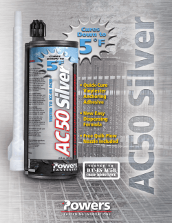

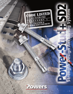
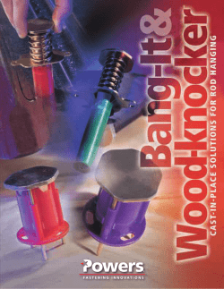
© Copyright 2026