
Hi-Res - Powers Fasteners
PRODUCT INFORMATION Mechanical anchors are available in many variations and choices and can usually be loaded immediately after installation which may be an advantage in many applications. Steel mechanical anchors also generally have a greater resistance to the effects of elevated temperature when compared with adhesives such as ester based resins or epoxies. Mechanical anchors can also be described by their style (e.g. undercut, expansion, screw, etc.). Mechanical Anchors SECTION CONTENTS Selection Guide............................ 32 Undercut Anchors Atomic+ UndercutTM ................... 34 Expansion Anchors Undercut anchors Undercut anchors expand at the bottom of the drilled hole similar to a compression type anchor except that the actual diameter of the expanded area is wider than the drilled hole, undercutting the base material similar to a dove tail slot. Anchors of this type can be self undercutting or may require a secondary drilling operation to form the undercut at the bottom of the drilled hole. During installation, as the expansion mechanism undercuts the base material, it forms a large bearing area which can transfer greater load to the base material. Power-Bolt™ ............................... 43 Power-Stud+® SD1...................... 54 Power-Stud+® SD2...................... 66 Power-Stud+® (MG, SS)............... 74 Lok-Bolt AS® ............................... 89 Screw Anchors Expansion anchors Wedge-Bolt+.............................. 96 Expansion anchors can be used to describe the majority of concrete and masonry anchors. Anchors of this type are designed with an expansion mechanism that compresses against the base material. Wedge-Bolt® (OT & 410 SS)...... 113 Tapper+® .................................. 130 The expansion mechanism may be a sleeve, slotted shell, slotted stud, or wedge assembly which is actuated by a tapered cone, tapered plug, nail, bolt, or screw depending upon the anchor style. The compression of the expansion mechanism against the wall of the drilled hole allows the anchor to transfer the load to the base material. Anchors which are expanded by tightening a bolt or nut are considered to be torque controlled while those that are actuated by driving a nail or plug are considered to be deformation controlled. A deformation controlled anchor can develop a higher initial compression force when compared to a torque controlled anchor. Compression anchors may also be pre-expanded and/or used in conjuction with a drive nail. The expansion mechanism on an anchor of this style is actuated as it is compressed during the driving operation into the anchor hole. Tapper® (SS) ............................. 139 Snake+® ................................... 146 Dropin Anchors Steel DropinTM .......................... 155 Mini DropinTM ........................... 162 Hollow-Set DropinTM ................. 166 Double ..................................... 173 ADHESIVES Screw anchors develop their load capacity by tapping into and creating an interlock between the anchor and the base material. I n the most common systems, an undersized hole is drilled into the base material. As the anchor is driven in, a keying/friction force is developed between the shank of the anchor and the base material. This type of anchor can be suitable for sustaining light to heavy duty loads depending on the anchor design. Single ....................................... 177 Calk-In...................................... 179 Lag Shield ................................ 182 Rod Hanger Anchors/Inserts Vertigo+................................... 185 MECHANICAL ANCHORS Bolt/Shield Anchors Screw anchors Vertigo®.................................... 194 Bang-ItTM / Wood-KnockerTM ....... 200 Pin/Nail Anchors Spike® ...................................... 207 Drive® ....................................... 221 Heli-Pin .................................... 225 Safe-T+ Pin .............................. 228 Zamac Hammer-Screw® ............ 232 Zamac Nailin® .......................... 236 Powers USA: (800) 524-3244 or (914) 235-6300 Canada: (905) 673-7295 or (514) 631-4216 www.powers.com 31 Selection Guide PRODUCT INFORMATION Anchor Category Undercut Anchors Product Atomic+ Undercut Power-Bolt Power-Stud+ SD1 Power-Stud+ SD2 Power-Stud (MG, SS) Lok-Bolt AS Wedge-Bolt+ Wedge-Bolt (OT,SS) Tapper+ Tapper (SS) Snake+ Steel Dropin Mini Dropin Hollow-Set Dropin May be Suitable MECHANICAL ANCHOR SELECTION GUIDE Page 34 43 54 66 74 89 96 113 130 139 146 155 162 166 ■ ■ ■ ■ ■ ■ ■ ■ ■ ■ □ ■ ■ □ □ ■ ■ ■ ■ ■ ■ ■ ■ ■ □ □ □ ■ ■ ■ ■ ■ ■ □ ■ ■ ■ □ □ □ ■ ■ □ ■ □ ■ ■ ■ ■ □ □ ■ ■ □ ■ □ ■ □ □ □ □ ■ ■ ■ ■ ■ ■ □ □ ■ ■ ■ ■ ■ ■ ■ ■ ■ ■ ■ ■ ■ ■ ■ ■ ■ ■ ■ ■ ■ ■ ■ ■ ■ ■ ■ ■ ■ ■ ■ ■ ■ ■ ■ ■ ■ ■ ■ ■ ■ ■ ■ ■ ■ ■ ■ ■ ■ ■ ■ ■ ■ ■ ■ ■ ■ ■ ■ ■ ■ Suitable □ Concrete Lightweight Concrete ■ Base Material Legend Hollow Core Plank Grout-filled Concrete Masonry Hollow Concrete Masonry Solid Brick Hollow Brick Stone Expansion Anchors □ □ □ Structural Clay Tile Screw Anchors ■ ■ Wood ■ Dropin Anchors ■ Steel #8-32 #10-24 3/16" Anchor Diameter 1/4" 5/16" 3/8" 1/2" 5/8" 3/4" 7/8" 1" 1-1/4" Stud ■ ■ ■ ■ ■ ■ ■ ■ ■ ■ ■ ■ ■ ■ ■ ■ ■ Finished Hex Head ■ ■ ■ ■ ■ ■ Head Style ■ Flat Head (Countersunk) ■ ■ ■ Round / Acorn Nut ■ ■ ■ ■ Mushroom Head ■ Tie-Wire Head ■ Tamperproof ■ Female / Rod Coupler Flush Mount Working Load (Concrete) Removable Under 500 lbs. 500 lbs. to 5,000 lbs. Over 5,000 lbs. Zinc Plated Carbon Steel ■ ■ ■ ■ ■ ■ ■ ■ ■ Galvanized Steel Coating / Material ■ ■ ■ ■ ■ ■ Type 303/304 Stainless Steel Type 316 Stainless Steel ■ ■ ■ ■ ■ ■ ■ ■ ■ ■ ■ ■ ■ ■ ■ ■ ■ ■ ■ ■ ■ ■ ■ ■ ■ ■ ■ ■ ■ ■ ■ ■ ■ ■ ■ Type 410 Stainless Steel ■ ■ ■ ■ ■ ■ ■ Zamac Alloy ■ Perma-Seal Coated Nylon / Plastic Lead 32 www.powers.com Canada: (905) 673-7295 or (514) 631-4216 Powers USA: (800) 524-3244 or (914) 235-6300 Selection Guide PRODUCT INFORMATION MECHANICAL ANCHOR SELECTION GUIDE Vertigo+ Vertigo Bang-It / Woodknocker Spike Drive Heli-Pin Safe-T+ Pin Zamac HammerScrew Zamac Nailin 225 228 232 236 ■ ■ ■ ■ ■ □ ■ ■ ■ ■ ■ □ □ □ □ □ □ □ ■ ■ ■ ■ ■ □ ■ □ ■ □ ■ □ ■ ■ □ □ ■ ■ ■ □ □ ■ □ □ ■ ■ ■ □ □ ■ ■ ■ ■ 8mm 8mm ■ ■ ■ ■ ■ ■ ■ ■ ■ ■ ■ ■ ■ ■ ■ ■ ■ ■ ■ ■ □ ■ □ ■ ■ ■ □ □ Suitable 179 Hollow Core Plank Grout-filled Concrete Masonry Hollow Concrete Masonry Solid Brick Hollow Brick Stone Structural Clay Tile Steel #8-32 #10-24 Anchor Diameter 3/16" 1/4" 5/16" 3/8" 1/2" 5/8" 3/4" ■ ■ ■ ■ ■ ■ ■ ■ ■ ■ ■ ■ ■ ■ ■ ■ ■ ■ ■ ■ ■ ■ ■ ■ ■ ■ ■ ■ ■ ■ ■ 7/8" □ ADHESIVES ■ ■ Wood ■ 1" 1-1/4" Stud Finished Hex Head ■ ■ Head Style Round / Acorn Nut ■ ■ ■ ■ Flat Head (Countersunk) Mushroom Head Tie-Wire Head Tamperproof Female / Rod Coupler Flush Mount ■ ■ Working Load (Concrete) Removable Under 500 lbs. 500 lbs. to 5,000 lbs. ■ ■ ■ ■ ■ ■ ■ ■ ■ ■ ■ ■ ■ ■ ■ ■ ■ ■ ■ ■ ■ ■ ■ ■ ■ ■ MECHANICAL ANCHORS Lag Shield 221 ■ ■ ■ Calk-In 207 ■ ■ Single 200 177 ■ Base Material 194 173 Lightweight Concrete Pin / Nail Anchors 185 Page Concrete Rod Hanger Anchors 182 Product Legend □ Bolt/Shield Anchors Double May be Suitable Anchor Category ■ ■ ■ Over 5,000 lbs. Zinc Plated Carbon Steel Coating / Material Galvanized Steel ■ Type 303/304 Stainless Steel ■ Type 316 Stainless Steel Type 410 Stainless Steel Zamac Alloy ■ ■ Perma-Seal Coated ■ Nylon / Plastic Lead Powers USA: (800) 524-3244 or (914) 235-6300 ■ Canada: (905) 673-7295 or (514) 631-4216 www.powers.com 33 Atomic+ Undercut™ PRODUCT INFORMATION Atomic+ Undercut™ Anchor PRODUCT DESCRIPTION SECTION CONTENTS The Atomic+ Undercut anchor is designed for applications in cracked and uncracked concrete. The anchors are available in standard ASTM A 36 steel, high strength ASTM A 193 Grade B7 high strength steel and Type 316 stainless steel designations. General Information The Type 316 stainless steel version can be considered for exterior use and industrial applications where a high level of corrosion resistance is required. Anchor Specifications The Atomic+ Undercut anchor is installed into a pre-drilled hole which has been enlarged at the bottom in the shape of a reversed cone using the Powers Undercut drill bit. The result is an anchor which transfers load mainly through bearing, and unlike a typical expansion anchor is not dependent upon friction between the expansion sleeve and the concrete. Due to the use of a thick walled expansion sleeve, the load is distributed to a large area which can provide ductile behavior of the anchor even at relatively shallow embedments. Installation Instructions Material Specifications Installation Specifications Performance Data Factored Design Strength Ordering Information GENERAL APPLICATIONS AND USES • Structural connections, i.e. beam and column anchorage • Safety related attachments • Tension zone applications, i.e. cable trays and strut, pipe supports, fire sprinkler • Seismic and wind loading • Heavy duty loading Atomic+ Undercut Assembly FEATURES AND BENEFITS THREAD VERSION + Consistent performance in high and low strength concrete + Anchors available for standard installations and for through bolt applications where the fixture is already in place + Length ID code and identifying marking stamped on head of each anchor + Load transfers to concrete through bearing, not friction + Bearing load transfer allows for closer spacing and edge distances. + Can be designed for predictable ductile steel performance behaves like a cast in place bolt. + Undercut created in seconds with durable tool UNC threaded stud ANCHOR MATERIALS Carbon Steel High Strength Carbon Steel Type 316 Stainless Steel APPROVALS AND LISTINGS ANCHOR SIZE RANGE (TYP.) International Code Council, Evaluation Service (ICC-ES), ESR-3067 Code compliant with the 2009 IBC, 2009 IRC, 2006 IBC, 2006 IRC, 2003 IBC, and 2003 IRC Tested in accordance with ACI 355.2 and ICC-ES AC193 for use in structural concrete under the design provisions of ACI 318 (Strength Design method using Appendix D) Evaluated and qualified by an accredited independent testing laboratory for recognition in cracked and uncracked concrete including seismic and wind loading (Category 1 anchors) 3/8” diameter through 3/4” diameter SUITABLE BASE MATERIALS Normal-weight concrete Structural sand-lightweight concrete GUIDE SPECIFICATIONS CSI Divisions: 03151-Concrete Anchoring and 05090 - Metal Fastening. Undercut anchors shall be Atomic+ Undercut anchors as supplied by Powers Fasteners, Inc., Brewster, NY. Anchors shall be installed in accordance with published instructions and the Authority Having Jurisdiction. MATERIAL SPECIFICATIONS This Product Available In Anchor Designation AnchorComponent Threaded Rod High Strength ASTM A 193 Grade B7 Type 316 Stainless Steel ASTM A 36 ASTM A 193 Grade B7 Type 316 Stainless Steel Powers Design Assist Expansion Coupling ASTM A 108 12L14 ASTM A 108 12L14 Type 316 Stainless Steel Expansion/Spacer Sleeve ASTM A 513 Type 5 ASTM A 513 Type 5 Type 316 Stainless Steel Type 316 Stainless Steel, ASTM A 563, Grade A Type 316 Stainless Steel, ASTM F 844, meets dimensional requirements of ANSI B18,22.2, Type A Real Time Anchor Design Software www.powersdesignassist.com Hex Nuts 34 Standard ASTM A 36 Carbon Steel, ASTM A 563, Grade A Washer Carbon Steel, ASTM A 844; Meets dimensional requirments of ANSI B18. 2.22.2, Type A Plain Plating Zinc Plating according to ASTM B 633, SC1, Type III (Fe/Zn 5) Minimum plating requirement for Mild Service Condition www.powers.com N/A Canada: (905) 673-7295 or (514) 631-4216 Powers USA: (800) 524-3244 or (914) 235-6300 Atomic+ Undercut™ PRODUCT INFORMATION ANCHOR SPECIFICATIONS Dimensional Characteristics Table for Atomic+ Undercut Anchor Type Anchor Rod ASTM Designation Rod Diameter, db (inch) Anchor Length, lb (inches) Sleeve Length, ls (inches) Sleeve Diameter, ds (inch) Expansion Coupling Diameter dc (inch) Max. Fixture Thickness, t (inches) 03100SD Standard A 36 3/8 5-1/2 2-3/4 5/8 5/8 1-3/4 03102SD Through bolt (TB) A 36 3/8 5-1/2 4-1/2 5/8 5/8 1-3/4 03600SD Standard Type 316 SS 3/8 5-1/2 2-3/4 5/8 5/8 1-3/4 03602SD Through bolt (TB) Type 316 SS 3/8 5-1/2 4-1/2 5/8 5/8 1-3/4 Standard A 193, Grade B7 3/8 6-3/4 4 5/8 5/8 1-3/4 Through bolt (TB) A 193, Grade B7 3/8 6-3/4 5-3/4 5/8 5/8 1-3/4 Anchor Designation 03104SD 03106SD 03108SD Standard A 36 1/2 7 4 3/4 3/4 1-3/4 03110SD Through bolt (TB) A 36 1/2 7 5-3/4 3/4 3/4 1-3/4 03608SD Standard Type 316 SS 1/2 7 4 3/4 3/4 1-3/4 03610SD Through bolt (TB) Type 316 SS 1/2 7 5-3/4 3/4 3/4 1-3/4 03112SD Standard A 193, Grade B7 1/2 8 5 3/4 3/4 1-3/4 Through bolt (TB) A 193, Grade B7 03114SD 03116SD 03118SD 1/2 8 6-3/4 3/4 3/4 1-3/4 A 193, Grade B7 1/2 9-3/4 6-3/4 3/4 3/4 1-3/4 Through bolt (TB) A 193, Grade B7 Standard 1/2 9-3/4 8-1/2 3/4 3/4 1-3/4 A 36 5/8 7-3/4 4-1/2 1 1 1-3/4 Through bolt (TB) A 36 5/8 7-3/4 6-1/4 1 1 1-3/4 Standard Type 316 SS 5/8 7-3/4 4-1/2 1 1 1-3/4 Through bolt (TB) Type 316 SS 5/8 7-3/4 6-1/4 1 1 1-3/4 Standard A 193, Grade B7 5/8 10-3/4 7-1/2 1 1 1-3/4 Through bolt (TB) A 193, Grade B7 03120SD Standard 03122SD 03620SD 03622SD 03124SD 03126SD 03128SD 03130SD 5/8 10-3/4 9-1/4 1 1 1-3/4 A 193, Grade B7 5/8 12-1/4 9 1 1 1-3/4 Through bolt (TB) A 193, Grade B7 5/8 12-1/4 10-3/4 1 1 1-3/4 Standard 03132SD Standard A 36 3/4 8-5/8 5 1-1/8 1-1/8 1-3/4 03134SD Through bolt (TB) A 36 3/4 8-5/8 6-3/4 1-1/8 1-1/8 1-3/4 03632SD Standard Type 316 SS 3/4 8-5/8 5 1-1/8 1-1/8 1-3/4 03634SD Through bolt (TB) Type 316 SS 3/4 8-5/8 6-3/4 1-1/8 1-1/8 1-3/4 Standard A 193, Grade B7 3/4 13-5/8 10 1-1/8 1-1/8 1-3/4 Through bolt (TB) A 193, Grade B7 3/4 13-5/8 11-3/4 1-1/8 1-1/8 1-3/4 03136SD 03138SD Atomic+ Undercut Anchor Detail Head Marking C+ Legend Letter Code = Length Identification Mark ‘+’ Symbol = Strength Design Compliant Anchor (see ordering information) Length Identification Mark A B C D E F From 1-1/2" 2" 2-1/2" 3" 3-1/2" 4" Up to but not including 2" 2-1/2" 3" 3-1/2" 4" 4-1/2" Mark G H I J K L From 4-1/2" 5" 5-1/2" 6" 6-1/2" 7" Up to but not including 5" 5-1/2" 6" 6-1/2" 7" 7-1/2" Mark M N O P Q R W T From 7-1/2" 8" 8-1/2" 9" 9-1/2" 10" 11" 12" 8" 8-1/2" 9" 9-1/2" 10" 11" 12" 13" Up to but not including Length identification mark indicates overall length of anchor. Powers USA: (800) 524-3244 or (914) 235-6300 Canada: (905) 673-7295 or (514) 631-4216 www.powers.com 35 Atomic+ Undercut™ PRODUCT INFORMATION INSTALLATION SPECIFICATIONS Installation Specifications for Atomic+ Undercut Anchors Anchor Property/Setting Information Nominal Anchor Diameter Notation Units 3/8 inch 1/2 inch 5/8 inch 3/4 inch da [do ]3 in. (mm) 0.625 (15.9) 0.750 (19.1) 1.000 (25.4) 1.125 (28.6) dh in. (mm) 7/16 (11.1) 9/16 (14.3) 11/16 (17.5) 13/16 (20.6 hnom in. (mm) 3-1/8 (79) 4-3/8 (111) 4-1/4 (108) 5-1/4 (133) 7 (178) 5 (127) 8 (203) 9-1/2 (241) 5-7/8 (149) 10-7/8 (276) Effective embedment hef in. (mm) 2-3/4 (68) 4 (102) 4 (102) 5 (127) 6-3/4 (171) 4-1/2 (114) 7-1/2 (190) 9 (229) 5 (127) 10 (254) Minimum hole depth1 ho in. (mm) 3-1/8 (79) 4-3/8 (111) 4-1/4 (108) 5-1/4 (133) 7 (178) 5 (127) 8 (204) 9-1/2 (241) 5-7/8 (149) 10-7/8 (276) hmin in. (mm) 5-1/2 (140) 8 (204) 8 (204) 10 (254) 13-1/2 (343) 9 (229) 15 (381) 18 (457) 10 (254) 20 (508) for cac ≥ in. (mm) 4-1/8 (105) 6 (152) 6 (152) 7-1/2 (190) 10-1/8 (257) 6-3/4 (171) 11-1/4 (256) 13-1/2 (343) 7-1/2 (190) 15 (381) hmin in. (mm) 4-3/8 (111) 6 (152) 6 (152) 7-1/2 (190) 10-1/8 (257) 6-3/4 (171) 11-1/4 (256) 13-1/2 (343) 7-1/2 (190) 15 (381) for cac ≥ in. (mm) 5-1/2 (140) 10-1/4 (260) 9-1/4 (235) 13 (330) 20-1/4 (514) 9-1/2 (241) 21 (533) 27 (686) 10-1/2 (267) 30 (762) Minimum edge distance cmin in. (mm) 2-1/4 (57) 3-1/4 (82) 3-1/4 (82) 4 (102) 5-3/8 (86) 3-5/8 (92) 6 (152) 7-1/4 (184) 4 (102) 8 (204) Minimum spacing distance smin in. (mm) 2-3/4 (70) 4 (102) 4 (102) 5 (127) 6-3/4 (171) 4-1/2 (114) 7-1/2 (190) 9 (229) 5 (127) 10 (254) t in. (mm) 1-3/4 (44) 1-3/4 (44) 1-3/4 (44) 1-3/4 (44) Tinst ft.-lbf. 26 44 60 133 Torque wrench / socket size - in. 9/16 3/4 15/16 1-1/8 Nut Height - in. 21/64 7/16 35/64 41/64 dbit in. 5/8 ANSI 3/4 ANSI 1 ANSI 1-1/8 ANSI Stop drill bit for anchor installation - - 3220SD 3221SD 3222SD 3223SD 3224SD 3225SD 3226SD 3227SD 3228SD 3229SD Drilled hole depth of stop bit1 - - 3-1/8 4-3/8 4-1/4 5-1/4 7 5 8 9-1/2 5-7/8 10-7/8 Stop drill bit shank type - - Outside anchor diameter Minimum diameter of hole clearance in fixture2 Minimum nominal embedment depth Minimum concrete member thickness Maximum thickness of fixture Maximum torque Stop Drill Bit Nominal stop drill bit diameter SDS SDS SDS-Max SDS-Max Undercut Drill Bit Nominal undercut drill bit diameter duc in. 5/8 3/4 1 1-1/8 Undercut drill bit designation - - 3200SD 3201SD 3202SD 3203SD Maximum depth of hole for undercut drill bit - in. (mm) 9 (229) 10-1/4 (260) 12-1/4 (311) 13-1/2 (343) Undercut drill bit shank type - - SDS SDS SDS-Max SDS-Max Required impact drill energy - ft.-lbf. 1.6 2.5 3.2 4.0 3211SD 3212SD 3213SD Setting Sleeve Recommended setting sleeve - - 3210SD For SI: 1 inch = 25.4 mm, 1 ft-lbf = 1.356 N-m. 1. For through bolt applications the actual hole depth is given by the minimum hole depth plus the maximum thickness of fixture less the thickness of the actual part(s) being fastened to the base material (ho,act = ho + t – tpl ) . 2. For through bolt applications the minimum diameter of hole clearance in fixture is 1/16-inch larger than the nominal outside anchor diameter. 3. The notation in brackets is for the 2006 IBC. 36 www.powers.com Canada: (905) 673-7295 or (514) 631-4216 Powers USA: (800) 524-3244 or (914) 235-6300 Atomic+ Undercut™ PRODUCT INFORMATION INSTALLATION INSTRUCTIONS Installation Instructions for Atomic+ Undercut Anchors 1.) Drill the hole to proper depth and diameter per specifications using rotohammer and stop drill. 2.) Clean the hole using a blow-out bulb or compressed air. 3.) Insert the undercut bit and start the rotohammer. Undercutting is complete when the stopper sleeve is fully compressed (gap closed) 4.) Clean the hole using a blow-out bulb or compressed air. 5.) Insert anchor into hole. Place setting sleeve over anchor and drive the expansion sleeve over the expansion coupling. 6.) Verify that the setting mark is visible on the theaded rod above the sleeve. 7.) Apply proper torque. Atomic+ Undercut Anchor Detail (before and after application of setting sleeve and attachment) Powers USA: (800) 524-3244 or (914) 235-6300 Canada: (905) 673-7295 or (514) 631-4216 www.powers.com 37 Atomic+ Undercut™ PRODUCT INFORMATION PERFORMANCE DATA Tension and Shear Design Information For Atomic+ Undercut Anchor in Concrete (For use with load combinations taken from ACI 318 Section 9.2)1,2,3 Anchor Property / Setting Information Nominal Anchor Diameter Notation Units Anchor category 1,2 or 3 - Outside anchor diameter da [do ]9 hef in. (mm) in. (mm) Ase in.2 (mm2) Effective embedment 3/8 inch 1/2 inch 5/8 inch 3/4 inch 1.000 (25.4) 7-1/2 (190) 1.125 (28.6) 1 0.625 (15.9) 4 (102) 2-3/4 (68) 4 (102) 0.750 (19.1) 5 (127) 4-1/2 (114) 6-3/4 (171) STEEL STRENGTH IN TENSION AND SHEAR3 0.0775 0.1419 (50) (91) 9 (229) 10 (254) 5 (127) Tensile stress area of anchor rod steel Minimum specified yield strength of anchor rod10 Minimum specified ultimate tensile strength of anchor rod10 fy ksi (N/mm2) 36 (248) 105 (723) 36 (248) 105 (723) 105 (723) 36 (248) 105 (723) 105 (723) 36 (248) 105 (723) futa8 ksi (N/mm2) 58 (400) 125 (860) 58 (400) 125 (860) 125 (860) 58 (400) 125 (860) 125 (860) 58 (400) 125 (860) Steel strength in tension, static10 Nsa8 Steel strength in shear, static10 Vsa8 Steel strength in shear, seismic10 Veq8 lb (kN) lb (kN) lb (kN) 4,495 (20.1) 2,245 (10.0) 2,245 (10.0) 9,685 (43.2) 4,885 (21.7) 4,885 (21.7) 8,230 (36.7) 4,110 (18.4) 4,110 (18.4) 17,735 (79.1) 8,855 (39.5) 8,855 (39.5) 17,735 (79.1) 8,855 (39.5) 8,855 (39.5) 13,100 (58.5) 6,560 (29.3) 6,560 (29.3) 28,250 (126.1) 14,110 (63.0) 14,110 (63.0) 28,250 (126.1) 14,110 (63.0) 14,110 (63.0) 19,400 (86.3) 9,685 (43.2) 9,685 (43.2) 41,810 (186.0) 20,875 (93.2) 20,875 (93.2) Minimum specified yield strength of anchor rod (Type 316 stainless steel anchor) fy,ss ksi (N/mm2) 30 (205) - 30 (205) - - 30 (205) - - 30 (205) - Minimum specified ultimate tensile strength of anchor rod (Type 316 stainless steel anchor) futa,ss8 - - - Nsa,ss8 - - - - Steel strength in shear, static (Type 316 stainless steel anchor) 11 Reduction factor for steel strength in tension2 Reduction factor for steel strength in shear2 Vsa,ss8 75 (515) 4,415 (19.6) 2,650 (11.8) - Steel strength in tension, static (Type 316 stainless steel anchor)11 ksi (N/mm2) lb (kN) lb (kN) - - - - f - 0.75 - 0.65 f - 75 (515) 8,085 (36.0) 4,850 (21.6) 0.2260 (146) 75 (515) 12,880 (57.3) 7,725 (34.4) 0.3345 (216) 75 (515) 19,065 (84.8) 11,440 (50.9) - CONCRETE BREAKOUT STRENGTH IN TENSION AND SHEAR7 Effectiveness factor for uncracked concrete Effectiveness factor for cracked concrete Modification factor for cracked and uncracked concrete4 Reduction factor for concrete breakout strength in tension2 Reduction factor for concrete breakout strength in shear2 kuncr kcr - 30 30 30 30 - 24 24 24 24 Ψc,N 8 - 1 (See note 4) 1 (See note 4) 1 (See note 4) 1 (See note 4) f - f - See note 6 See note 6 0.65 (Condition B) 0.70 (Condition B) PULLOUT STRENGTH IN TENSION7 Characteristic pullout strength, uncracked concrete (2,500 psi)5 Characteristic pullout strength, cracked concrete (2,500 psi)5 Characteristic pullout strength, seismic (2,500 psi)5,10 Reduction factor for pullout strength2 Np,cr lb (kN) lb (kN) See note 6 Neq 8 lb (kN) See note 6 f - kcp f - Np,uncr See note 6 9,000 (40.2) 9,000 (40.2) See note 6 11,500 (51.3) 11,500 (51.3) See note 6 See note 6 15,000 (67.0) 15,000 (67.0) See note 6 See note 6 22,000 (98.2) 22,000 (98.2) See note 6 See note 6 0.65 (Condition B) PRYOUT STRENGTH IN SHEAR7 Coefficient for pryout strength Reduction factor for pryout strength2 2.0 2.0 - 2.0 2.0 0.70 (Condition B) For SI: 1 inch = 25.4 mm, 1 ksi = 6.895 MPa (N/mm2), 1 lbf = 0.0044 kN, 1 in2 = 645 mm2. 1. The data in this table is intended to be used with the design provisions of ACI 318 Appendix D; for anchors resisting seismic load combinations the additional requirements of ACI 318 D.3.3 shall apply. 2. All values of f were determined from the load combinations of IBC Section 1605.2, ACI 318 Section 9.2 or UBC Section 1612.2. If the load combinations of ACI 318 Appendix C or IBC Section 1909.2 are used, the appropriate value of f must be determined in accordance with ACI 318 D.4.5. For reinforcement that meets ACI 318 Appendix D requirements for Condition A, see ACI 318 D.4.4 for the appropriate Ø factor. 3. Anchors are considered a ductile steel element as defined by ACI 318 D.1. 4. For all design cases Ψc,N =1.0. The appropriate effectiveness factor for cracked concrete (kcr) or uncracked concrete (kuncr) must be used. 5. For all design cases Ψc,P =1.0. For concrete compressive strength greater than 2,500 psi, Npn = (pullout strength value from table)*(specified concrete compressive strength/2500)0.5. 6. Pullout strength does not control design of indicated anchors. Do not calculate pullout strength for indicated anchor size and embedment. 7. Anchors are permitted to be used in structural sand-lightweight concrete provided that Nb, Neq and Npn mulitplied by a factor of 0.60. 8. For 2003 IBC code basis, futa replaces fut ; Nsa replaces Ns ; Ψc,N replaces Ψ3; and Neq replaces Np,seis ; and Veq replaces Vsa,seis. 9. The notation in brackets is for the 2006 IBC. 10. Only Applicapable for carbon steel anchors. 11. Calculated using futa,ss = 57 ksi (1.9 fy) in accordance with ACI 318 Appendix D. 38 www.powers.com Canada: (905) 673-7295 or (514) 631-4216 Powers USA: (800) 524-3244 or (914) 235-6300 Atomic+ Undercut™ PRODUCT INFORMATION Factored Design Strength (fNn and fVn) Calculated in Accordance with ACI 318 Appendix D: 1. Tabular values are provided for illustration and are applicable for single anchors installed in normal-weight-concrete with minimum slab thickness, ha = hmin , and with the following conditions: - ca1 is greater than or equal to the critical edge distance, cac (table values based on ca1 = cac ). Ca1 - ca2 is greater than or equal to 1.5 ca1. ha Ca2 2. Calculations were performed according to ACI 318-05 Appendix D. The load level corresponding to the controlling failure mode is listed. (e.g. For tension: steel, concrete breakout and pullout; For shear: steel, concrete breakout and pryout). Furthermore, the capacities for concrete breakout strength in tension and pryout strength in shear are calculated using the effective embedment values, hef, for the selected anchors as noted in the design information tables. Please also reference the installation specifications for more information. 3. Strength reduction factors (f) Were based on ACI 318 Section 9.2 for load combinations. Condition B is assumed. 4. Tabular values are permitted for static loads only, seismic loading is not considered with these tables. 5. For designs that include combined tension and shear, the interaction of tension and shear loads must be calculated in accordance with ACI 318 Appendix D. 6. Interpolation is not permitted to be used with the tabular values. For intermediate base material compressive strengths please see ACI 318 Appendix D. For other design conditions including seismic considerations please see ACI 318 Appendix D. Tension and Shear Design Strength for Carbon Steel Atomic+ Undercut in Cracked Concrete Minimum Concrete Compressive Strength, f'c (psi) Nominal Anchor Size (in.) Nominal Embed. hnom (in.) fNn Tension (lbs.) fVn Shear (lbs.) fNn Tension (lbs.) fVn Shear (lbs.) fNn Tension (lbs.) fVn Shear (lbs.) fNn Tension (lbs.) fVn Shear (lbs.) fNn Tension (lbs.) fVn Shear (lbs.) 3/8 3-1/8 3,370 1,460 3,370 1,460 3,370 1,460 3,370 1,460 3,370 1,460 3/8 4-3/8 5,850 3,155 6,410 3,155 7,265 3,155 7,265 3,155 7,265 3,155 1/2 4-1/4 6,175 2,670 6,175 2,670 6,175 2,670 6,175 2,670 6,175 2,670 1/2 5-1/4 7,475 5,755 8,190 5,755 9,455 5,755 11,580 5,755 13,300 5,755 1/2 7 7,475 5,755 8,190 5,755 9,455 5,755 11,580 5,755 13,300 5,755 5/8 5 7,445 4,265 8,155 4,265 9,420 4,265 9,825 4,265 9,825 4,265 5/8 8 9,750 9,170 10,680 9,170 12,335 9,170 15,105 9,170 17,440 9,170 5/8 9-1/2 9,750 9,170 10,680 9,170 12,335 9,170 15,105 9,170 17,440 9,170 3/4 5-7/8 8,720 6,295 9,555 6,295 11,030 6,295 13,510 6,295 14,550 3/4 10-7/8 14,300 13,570 15,665 13,570 18,090 13,570 22,155 13,570 25,580 6,295 13,570 2,500 3,000 4,000 6,000 8,000 Tension and Shear Design Strength for Carbon Steel Atomic+ Undercut in Uncracked Concrete Nominal Anchor Size (in.) Nominal Embed. hnom Minimum Concrete Compressive Strength, f'c (psi) 2,500 3,000 4,000 6,000 8,000 (in.) fNn Tension (lbs.) fVn Shear (lbs.) fNn Tension (lbs.) fVn Shear (lbs.) fNn Tension (lbs.) fVn Shear (lbs.) fNn Tension (lbs.) fVn Shear (lbs.) fNn Tension (lbs.) fVn Shear (lbs.) 3/8 3-1/8 3,370 1,460 3,370 1,460 3,370 1,460 3,370 1,460 3,370 1,460 3/8 4-3/8 7,265 3,155 7,265 3,155 7,265 3,155 7,265 3,155 7,265 3,155 1/2 4-1/4 6,175 2,670 6,175 2,670 6,175 2,670 6,175 2,670 6,175 2,670 1/2 5-1/4 10,900 5,755 11,940 5,755 13,300 5,755 13,300 5,755 13,300 5,755 1/2 7 13,300 5,755 13,300 5,755 13,300 5,755 13,300 5,755 13,300 5,755 5/8 5 9,305 4,265 9,825 4,265 9,825 4,265 9,825 4,265 9,825 4,265 5/8 8 20,025 9,170 21,190 9,170 21,190 9,170 21,190 9,170 21,190 9,170 5/8 9-1/2 21,190 9,170 21,190 9,170 21,190 9,170 21,190 9,170 21,190 9,170 3/4 5-7/8 10,900 6,295 11,940 6,295 13,790 6,295 14,550 6,295 14,550 3/4 10-7/8 30,830 13,570 31,360 13,570 31,360 13,570 31,360 13,570 31,360 6,295 13,570 Steel Strength Controls Powers USA: (800) 524-3244 or (914) 235-6300 Concrete Breakout Strength Controls Canada: (905) 673-7295 or (514) 631-4216 Anchor Pullout/Pryout Strength Controls www.powers.com 39 Atomic+ Undercut™ PRODUCT INFORMATION Factored Design Strength (fNn and fVn) Calculated in Accordance with ACI 318 Appendix D: 1. Tabular values are provided for illustration and are applicable for single anchors installed in normal-weight concrete with minimum slab thickness, ha = hmin, and with the following conditions: ca1 is greater than or equal to the critical edge distance, cac (table values based on ca1 = cac) and ca2 is greater than or equal to 1.5 ca1. 2. Calculations were performed according to ACI 318-05 Appendix D. The load level corresponding to the controlling failure mode Ca1 is listed. (e.g. For tension: steel, concrete breakout and pullout; For shear: steel, concrete breakout and pryout). Furthermore, ha Ca2 the capacities for concrete breakout strength in tension and pryout strength in shear are calculated using the effective embedment values, hef, for the selected anchors as noted in the design information tables. Please also reference the installation specifications for more information. 3. Strength reduction factors (f) were based on ACI 318 Section 9.2 for load combinations. Condition B is assumed. 4. Tabular values are permitted for static loads only, seismic loading is not considered with stainless steel Atomic+ Undercut anchors. 5. For designs that include combined tension and shear, the interaction of tension and shear loads must be calculated in accordance with ACI 318 Appendix D. 6. Interpolation is not permitted to be used with the tabular values. For intermediate base material compressive strengths please see ACI 318 Appendix D. For other design conditions including seismic considerations please see ACI 318 Appendix D. Tension and Shear Factored Design Strength for Stainless Steel Atomic+ Undercut Anchor in Cracked Concrete Minimum Concrete Compressive Strength, f'c (psi) Nominal Anchor Size (in.) Nominal Embed. hnom (in.) fNn Tension (lbs.) fVn Shear (lbs.) fNn Tension (lbs.) fVn Shear (lbs.) fNn Tension (lbs.) fVn Shear (lbs.) fNn Tension (lbs.) fVn Shear (lbs.) fNn Tension (lbs.) fVn Shear (lbs.) 3/8 3-1/8 3,310 1,725 3,310 1,725 3,310 1,725 3,310 1,725 3,310 1,725 1/2 4-1/4 6,065 3,155 6,065 3,155 6,065 3,155 6,065 3,155 6,065 3,155 5/8 5 7,445 5,020 8,155 5,020 9,420 5,020 9,660 5,020 9,660 5,020 3/4 5-7/8 8,720 7,425 9,555 7,425 11,030 7,425 13,510 7,425 14,275 7,425 2,500 3,000 4,000 6,000 8,000 Tension and Shear Factored Design Strength for Stainless Steel Atomic+ Undercut Anchor in Uncracked Concrete Minimum Concrete Compressive Strength, f'c (psi) Nominal Anchor Size (in.) Nominal Embed. hnom (in.) fNn Tension (lbs.) fVn Shear (lbs.) fNn Tension (lbs.) fVn Shear (lbs.) fNn Tension (lbs.) fVn Shear (lbs.) fNn Tension (lbs.) fVn Shear (lbs.) fNn Tension (lbs.) fVn Shear (lbs.) 3/8 3-1/8 3,310 1,725 3,310 1,725 3,310 1,725 3,310 1,725 3,310 1,725 1/2 4-1/4 6,065 3,155 6,065 3,155 6,065 3,155 6,065 3,155 6,065 3,155 5/8 5 9,305 5,020 9,660 5,020 9,660 5,020 9,660 5,020 9,660 5,020 3/4 5-7/8 10,900 7,425 11,940 7,425 13,790 7,425 14,275 7,425 14,275 7,425 2,500 Steel Strength Controls 40 www.powers.com 3,000 4,000 Concrete Breakout Strength Controls Canada: (905) 673-7295 or (514) 631-4216 6,000 8,000 Anchor Pullout/Pryout Strength Controls Powers USA: (800) 524-3244 or (914) 235-6300 Atomic+ Undercut™ PRODUCT INFORMATION ORDERING INFORMATION Atomic+ Undercut Anchor A 36 Steel Cat. No. Nominal Anchor Diameter Overall Length 03100SD 3/8" 5-1/2" 03102SD 3/8" 5-1/2" 03108SD 1/2" 7" 03110SD 1/2" 7" 03120SD 5/8" 7-3/4" 03122SD 5/8" 7-3/4" 03132SD 3/4" 8-5/8" 03134SD 3/4" 8-5/8" Required Undercut Bit (Cat. No.) 03200SD 03201SD 03202SD 03203SD Recommended Stop Bit (Cat. No.) Anchor Type Std. Box 03220SD Standard 20 * Through bolt 20 03222SD Standard 15 * Through bolt 15 03225SD Standard 10 * Through bolt 10 03228SD Standard 8 * Through bolt 8 For availability of all anchors lengths please contact Powers Fasteners. *Contact Powers Fasteners for appropriate drilling method and hardware. Atomic+ Undercut Anchor High Strength A 193, Grade B7 Steel Cat. No. Nominal Anchor Diameter Overall Length 03104SD 3/8" 6-3/4" 03106SD 3/8" 6-3/4" 03112SD 1/2" 8" 03114SD 1/2" 8" 03116SD 1/2" 9-3/4" 03118SD 1/2" 9-3/4" 03124SD 5/8" 10-3/4" 03126SD 03128SD 03130SD 03136SD 03138SD 5/8" 5/8" 5/8" 3/4" 3/4" 10-3/4" 12-1/4" 12-1/4" 13-5/8" 13-5/8" Required Undercut Bit (Cat. No.) 03200SD 03201SD 03202SD 03203SD Recommended Stop Bit (Cat. No.) Anchor Type Std. Box 03221SD Standard 20 * Through bolt 20 03223SD Standard 15 * Through bolt 15 03224SD Standard 15 * Through bolt 15 03226SD Standard 10 * 03227SD * 03229SD * Through bolt Standard Through bolt Standard Through bolt 10 10 10 8 8 For availability of all anchors lengths please contact Powers Fasteners. *Contact Powers Fasteners for appropriate drilling method and hardware. Atomic+ Undercut Anchor Type 316 Stainless Steel Cat. No. Nominal Anchor Diameter Overall Length 03600SD 3/8" 5-1/2" 03602SD 3/8" 5-1/2" 03608SD 1/2" 7" 03610SD 1/2" 7" 03620SD 5/8" 7-3/4" 03622SD 5/8" 7-3/4" 03632SD 3/4" 8-5/8" 03634SD 3/4" 8-5/8" Required Undercut Bit (Cat. No.) 03200SD 03201SD 03202SD 03203SD Recommended Stop Bit (Cat. No.) Anchor Type Std. Box 03220SD Standard 20 * Through bolt 20 03222SD Standard 15 * Through bolt 15 03225SD Standard 10 * Through bolt 10 03228SD Standard 8 * Through bolt 8 For availability of all anchors lengths please contact Powers Fasteners. *Contact Powers Fasteners for appropriate drilling method and hardware. Powers USA: (800) 524-3244 or (914) 235-6300 Canada: (905) 673-7295 or (514) 631-4216 www.powers.com 41 Atomic+ Undercut™ PRODUCT INFORMATION ORDERING INFORMATION Stop Drill Bits Nominal Stop Drill Bit Corresponding Nominal Anchor Diameter Diameter 03220SD 5/8 3/8 Cat. No. Max. Drill Depth Shank Type Std. Tube 3-1/8" SDS 1 4-3/8" 4-1/4" 5-1/4" SDS SDS SDS 1 1 1 03221SD 03222SD 03223SD 5/8 3/4 3/4 3/8 1/2 1/2 03224SD 3/4 1/2 7" SDS 1 03225SD 1 5/8 5" SDS-Max 1 03226SD 1 5/8 8" SDS-Max 1 03227SD 1 5/8 9-1/2" SDS-Max 1 03228SD 1-1/8 3/4 5-13/16" SDS-Max 1 03229SD 1-1/8 3/4 10-13/16" SDS-Max 1 The Stop Drill Bit creates a drill hole to the proper depth for standard installations of the Atomic+ Undercut anchor (for through bolt applications please contact Powers Fasteners for appropriate drilling method and hardware). Undercut Drill Bits Corresponding Maximum Depth of Nominal Anchor Hole Diameter 3/8 9" Cat. No. Nominal Undercut Drill Bit Diameter Shank Type Std. Tube 03200SD 5/8 SDS 1 03201SD 3/4 1/2 10-1/4" SDS 1 03202SD 1 03203SD 1-1/8 5/8 12-1/4" SDS-Max 1 3/4 13-1/2" SDS-Max 1 The Undercut Drill Bit has a unique design that enlarges the bottom of the drill hole creating a reverse cone sized to receive the Atomic+ Undercut anchor. Undercut Setting Sleeve CAT. NO. 03210SD 03211SD 03212SD 03213SD Corresponding Nominal Anchor Diameter 3/8 1/2 5/8 3/4 Std. Box 1 1 1 1 Note: One Undercut Setting Sleeve is packaged with each box of Atomic+ Undercut anchors. © 2011 Powers Fasteners, Inc. All Rights Reserved. Atomic+ Undercut is a trademark of Powers Fasteners, Inc. For the most current product information please visit www.powers.com. 42 www.powers.com Canada: (905) 673-7295 or (514) 631-4216 Powers USA: (800) 524-3244 or (914) 235-6300 PRODUCT INFORMATION Power-Bolt™ Power-Bolt™ Heavy-Duty Sleeve Anchor PRODUCT DESCRIPTION SECTION CONTENTS The Power-Bolt anchor is a heavy duty sleeve style, self-locking anchor which is vibration resistant and removable. It is available with a finished hex head or flat head with a hex key insert and can be used in concrete, block, brick, or stone. General Information Expansion occurs at two locations within the drilled hole. First, the cone is pulled into the large tripletined expansion sleeve, developing a mid-level, compression force. Further turning causes the threaded bolt to advance into the threads of the expander cone, forcing its four sections outward. This action engages the base material deep in the anchor hole, greatly increasing the holding power of the PowerBolt. The bolt and cone remain locked together which prevents loosening under vibratory conditions. Material Specifications Installation Specifications Performance Data Design Criteria Ordering Information The Power-Bolt is also designed to draw the fixture into full bearing against the base material through the action of its flexible compression ring. As the anchor is being tightened, the compression ring will crush if necessary to tightly secure the fixture against the face of the base material. The internal bolt of the Power-Bolt is removable and reusable in the same anchor sleeve making it suitable for applications such as mounting machinery which may need to be removed for service and for temporary applications such as heavy duty form work. Hex Head Power-Bolt Assembly GENERAL APPLICATIONS AND USES • Column Base Plates and Mechanical Equipment • Dock Bumpers and Support Ledgers • Racking and Railing Attachments Flat Head Power-Bolt Assembly FEATURES AND BENEFITS HEAD STYLES + High load capacity + Two-level expansion mechanism + Internal high strength bolt is removable and reusable + Compression zone in sleeve clamps fixture to the base material + Low profile finished head design TESTING, APPROVALS AND LISTINGS Tested in accordance with ASTM E488 and AC01 criteria FM Global (Factory Mutual) – File No. J.I . 1K8A3.AH (See report for sizes) Underwriters Laboratories (UL Listed) – File No. EX1289 (See listing for sizes) ANCHOR MATERIALS Zinc Plated Carbon Steel Type 304 Stainless Steel ANCHOR SIZE RANGE (TYP.) 1/4" diameter through 3/4" diameter SUITABLE BASE MATERIALS APPROVALS AND LISTINGS CSI Divisions: 03151-Concrete Anchoring, 04081-Masonry Anchorage and 05090-Metal Fastenings. Expansion anchors shall be Power-Bolt as supplied by Powers Fasteners, I nc., Brewster, NY. Powers USA: (800) 524-3244 or (914) 235-6300 Finished Hex Head Flat Head Canada: (905) 673-7295 or (514) 631-4216 Normal-Weight Concrete Structural Lightweight Concrete Grouted Concrete Masonry (CMU) Hollow CMU Brick Masonry Stone www.powers.com 43 Power-Bolt™ PRODUCT INFORMATION INSTALLATION SPECIFICATIONS Carbon Steel Hex Head Power-Bolt Anchor Diameter, d Dimension ANSI Drill Bit Size, dbit (in.) Fixture Clearance Hole, dh (in.) Internal Bolt Size (UNC) Head Height (in.) Washer O.D., dw (in.) Wrench Size (in.) Max Bolt Torque, Tmax (ft-lbs) 1/4" 1/4 5/16 10-24 7/64 1/2 5/16 4 5/16" 5/15 3/8 1/4-20 11/64 5/8 7/16 12 3/8" 3/8 7/16 5/16-18 13/64 13/16 1/2 25 1/2" 1/2 9/16 3/8-16 15/64 1 9/16 45 5/8" 5/8 11/16 1/2-13 5/16 1-1/4 3/4 100 3/4" 3/4 13/16 1/2-13 25/64 1-1/2 15/16 120 Carbon Steel Flat Head Power-Bolt (80° – 82° head) Anchor Diameter, d Dimension ANSI Drill Bit Size, dbit (in.) Fixture Clearance Hole, dh (in.) Internal Bolt Size (UNC) Head Height (in.) Head Diameter, dhd (in.) Allen Wrench Size (in.) Max Bolt Torque, Tmax (ft-lbs) 3/8" 3/8 7/16 5/16-18 15/64 3/4 7/32 25 1/2" 1/2 9/16 3/8-16 1/4 7/8 5/16 45 5/8" 5/8 11/16 1/2-13 21/64 1-1/8 3/8 100 Stainless Steel Hex Head Power-Bolt Anchor Diameter, d Dimension ANSI Drill Bit Size, dbit (in.) Fixture Clearance Hole, dh (in.) Internal Bolt Size (UNC) Head Height (in.) Washer O.D., dw (in.) Wrench Size (in.) Max Bolt Torque, Tmax (ft-lbs) 1/4" 1/4 5/16 10-24 7/64 1/2 5/16 3 3/8" 3/8 7/16 5/16-18 13/64 13/16 1/2 12 1/2" 1/2 9/16 3/8-16 15/64 1 9/16 25 5/8" 5/8 11/16 1/2-13 5/16 1-1/4 3/4 60 3/4" 3/4 13/16 5/8-11 25/64 1-1/2 15/16 90 Installation Procedure Using the proper diameter bit, drill a hole into the base material to a depth of at least 1/2" or one anchor diameter deeper than the embedment required. The tolerances of the drill bit used must meet the requirements of ANSI Standard B212.15. Blow the hole clean of dust and other material. Do not modify the anchor or advance the bolt in the anchor assembly prior to installation. Drive the anchor through the fixture into the anchor hole until the bolt head is firmly seated against the fixture. Be sure the anchor is driven to the required embedment depth. Tighten the anchor by turning the head 3 to 4 turns past finger tight. Nomenclature d dbit dh dhd dw h hv l t 44 www.powers.com = Diameter of anchor = Diameter of drill bit = Diameter of fixture clearance hole = Flat head diameter = Diameter of washer = Base material thickness. The minimum value of h should be 1.5hv or 3”, whichever is greater = Minimum embedment depth = Length of anchor = Fixture thickness Canada: (905) 673-7295 or (514) 631-4216 Powers USA: (800) 524-3244 or (914) 235-6300 Power-Bolt™ PRODUCT INFORMATION MATERIAL SPECIFICATIONS Anchor Component Carbon Steel Hex Head Carbon Steel Flat Head Stainless Steel Hex Head Internal Bolt *SAE Grade 5 SAE Grade 5 Washer AISI 1040 N/A Type 18-8 SS Expander Sleeve AISI 1010 AISI 1010 Type 304 SS Extension Sleeve AISI 1010 AISI 1010 Type 304 SS **Type 304 SS Expander Cone AISI 12L14 AISI 12L14 Type 303 SS Compression Ring Nylon Nylon Nylon Dust Cap Nylon Nylon Nylon Zinc Plating ASTM B 633, SC1, Type III (Fe/Zn 5) – Mild Service Condition N/A Mark From Up to but not including A B C D E F G H I J K L M N O 1" 1-1/2" 2" 2-1/2" 3" 3-1/2" 4" 4-1/2" 5" 5-1/2" 6" 6-1/2" 7" 7-1/2" 8" 8-1/2" 1-1/2" 2" 2-1/2" 3" 3-1/2" 4" 4-1/2" 5" 5-1/2" 6" 6-1/2" 7" 7-1/2" 8" 8-1/2" 9" Powers USA: (800) 524-3244 or (914) 235-6300 Canada: (905) 673-7295 or (514) 631-4216 www.powers.com MECHANICAL ANCHORS Length Identification ADHESIVES *1/4" and 5/16" Diameter Power-Bolts are manufactured with SAE Grade 8 internal bolts. **Manufactured with a minimum yield strength of 65,000 psi. Stainless steel anchor components are passivated. The stainless steel expander cone is zinc plated. 45 Power-Bolt™ PRODUCT INFORMATION PERFORMANCE DATA Ultimate Load Capacities for Carbon and Stainless Steel Power-Bolt in Normal-Weight Concrete1,2 Anchor Diameter d in. (mm) 1/4 (6.4) 5/16 (7.9) 3/8 (9.5) 1/2 (12.7) 5/8 (15.9) 3/4 (19.1) Minimum Concrete Compressive Strength (f´c ) Minimum Embedment Depth hv in. (mm) 2,000 psi (13.8 MPa) 3,000 psi (20.7 MPa) 4,000 psi (27.6 MPa) 6,000 psi (41.4 MPa) Tension lbs. (kN) Shear lbs. (kN) Tension lbs. (kN) Shear lbs. (kN) Tension lbs. (kN) Shear lbs. (kN) Tension lbs. (kN) Shear lbs. (kN) 1-1/4 (31.8) 1,180 (5.3) 2,070 (9.3) 1,380 (6.2) 2,100 (9.5) 1,580 (7.1) 2,130 (9.6) 1,660 (7.5) 2,130 (9.6) 1-3/4 (44.5) 1,400 (6.3) 2,070 (9.3) 1,550 (7.0) 2,305 (10.4) 1,700 (7.7) 2,540 (11.4) 1,860 (8.4) 2,540 (11.4) 2-1/2 (63.5) 1,880 (8.5) 2,070 (9.3) 1,940 (8.7) 2,730 (12.3) 2,000 (9.0) 3,385 (15.2) 2,100 (9.5) 3,385 (15.2) 1-1/2 (38.1) 2,320 (10.4) 2,800 (12.6) 2,430 (10.9) 3,000 (13.5) 2,540 (11.4) 3,200 (14.4) 2,620 (11.8) 3,200 (14.4) 2 (50.8) 3 (76.2) 2,640 (11.9) 3,280 (14.8) 2,880 (13.0) 3,755 (16.9) 3,120 (14.0) 4,230 (19.0) 3,270 (14.7) 4,230 (19.0) 2,880 (13.0) 3,440 (15.5) 3,330 (15.0) 4,410 (19.8) 3,780 (17.0) 5,380 (24.2) 4,260 (19.2) 5,380 (24.2) 2 (50.8) 3,500 (15.8) 3,985 (17.9) 4,045 (18.2) 5,205 (23.4) 4,585 (20.6) 6,425 (28.9) 5,915 (26.6) 7,440 (33.5) 2-1/2 (63.5) 3-1/2 (88.9) 3,800 (17.1) 4,380 (19.7) 4,330 (19.5) 5,770 (26.0) 4,855 (21.8) 7,160 (32.2) 6,665 (30.0) 7,960 (35.8) 4,395 (19.8) 4,980 (22.4) 5,195 (23.4) 6,815 (30.7) 5,995 (27.0) 8,650 (38.9) 7,150 (32.2) 8,650 (38.9) 2-1/2 (63.5) 4,900 (22.1) 6,840 (30.8) 5,710 (25.7) 7,535 (33.9) 6,520 (29.3) 8,225 (37.0) 7,320 (32.9) 8,225 (37.0) 3-1/2 (88.9) 5 (127.0) 6,140 (27.6) 8,540 (38.4) 7,590 (34.2) 9,200 (41.4) 9,040 (40.7) 9,860 (44.4) 9,890 (44.5) 10,780 (48.5) 7,260 (32.7) 10,140 (45.6) 8,480 (38.2) 11,230 (50.5) 9,700 (43.7) 12,320 (55.4) 10,935 (49.2) 12,315 (55.4) 2-3/4 (69.9) 5,360 (24.1) 7,970 (35.9) 6,535 (29.4) 9,970 (44.9) 7,705 (34.7) 11,970 (53.9) 8,490 (38.2) 11,970 (53.9) 4 (101.6) 6 (152.4) 6,460 (29.1) 10,860 (48.9) 8,210 (36.9) 12,710 (57.2) 9,960 (44.8) 14,560 (65.5) 13,110 (59.0) 15,900 (71.6) 9,400 (42.3) 13,780 (62.0) 10,570 (47.6) 16,230 (73.0) 11,740 (52.8) 18,680 (84.1) 15,580 (70.1) 18,670 (84.0) 3 (76.2) 7,660 (34.5) 12,375 (55.7) 8,580 (38.6) 14,245 (64.1) 9,500 (42.8) 16,110 (72.5) 10,780 (48.5) 16,110 (72.5) 4-1/2 (114.3) 7 (177.8) 10,060 (45.3) 16,900 (76.1) 11,200 (50.4) 20,250 (91.1) 12,340 (55.5) 23,600 (106.2) 16,240 (73.1) 23,600 (106.2) 11,780 (53.0) 22,640 (101.9) 13,440 (60.5) 25,880 (116.5) 15,100 (68.0) 29,120 (131.0) 21,980 (98.9) 29,120 (131.0) 1. Tabulated load values are for anchors installed in concrete. Concrete compressive strength must be at the specified minimum at the time of installation. 2. Ultimate load capacities must be reduced by a minimum safety factor of 4.0 or greater to determine allowable working load. Consideration of safety factors of 10 or higher may be necessary depending upon the application such as life safety or overhead. 46 www.powers.com Canada: (905) 673-7295 or (514) 631-4216 Powers USA: (800) 524-3244 or (914) 235-6300 Power-Bolt™ PRODUCT INFORMATION PERFORMANCE DATA Allowable Load Capacities for Carbon and Stainless Steel Power-Bolt in Normal-Weight Concrete1,2,3 1/4 (6.4) 5/16 (7.9) 3/8 (9.5) 1/2 (12.7) 5/8 (15.9) 3/4 (19.1) Minimum Concrete Compressive Strength (f´c ) 2,000 psi (13.8 MPa) 3,000 psi (20.7 MPa) 4,000 psi (27.6 MPa) 6,000 psi (41.4 MPa) Tension lbs. (kN) Shear lbs. (kN) Tension lbs. (kN) Shear lbs. (kN) Tension lbs. (kN) Shear lbs. (kN) Tension lbs. (kN) Shear lbs. (kN) 295 (1.3) 515 (2.3) 345 (1.6) 525 (2.4) 395 (1.8) 535 (2.4) 415 (1.9) 530 (2.4) 350 (1.6) 515 (2.3) 390 (1.8) 575 (2.6) 425 (1.9) 635 (2.9) 465 (2.1) 635 (2.9) 470 (2.1) 515 (2.3) 485 (2.2) 680 (3.1) 500 (2.3) 845 (3.8) 525 (2.4) 845 (3.8) 580 (2.6) 700 (3.2) 610 (2.7) 750 (3.4) 635 (2.9) 800 (3.6) 655 (2.9) 800 (3.6) 660 (3.0) 820 (3.7) 720 (3.2) 940 (4.2) 780 (3.5) 1,060 (4.8) 820 (3.7) 1,060 (4.8) 720 (3.2) 860 (3.9) 835 (3.8) 1,105 (5.0) 945 (4.3) 1,345 (6.1) 1,065 (4.8) 1,345 (6.1) 875 (3.9) 995 (4.5) 1,010 (4.5) 1,300 (5.9) 1,145 (5.2) 1,605 (7.2) 1,480 (6.7) 1,860 (8.4) 950 (4.3) 1,095 (4.9) 1,080 (4.9) 1,445 (6.5) 1,215 (5.5) 1,790 (8.1) 1,665 (7.5) 1,990 (9.0) 1,100 (5.0) 1,245 (5.6) 1,300 (5.9) 1,705 (7.7) 1,500 (6.8) 2,165 (9.7) 1,790 (8.1) 2,165 (9.7) 1,225 (5.5) 1,710 (7.7) 1,430 (6.4) 1,885 (8.5) 1,630 (7.3) 2,055 (9.2) 1,830 (8.2) 2,055 (9.2) 1,535 (6.9) 2,135 (9.6) 1,900 (8.6) 2,300 (10.4) 2,260 (10.2) 2,465 (11.1) 2,470 (11.1) 2,695 (12.1) 1,815 (8.2) 2,535 (11.4) 2,120 (9.5) 2,810 (12.6) 2,425 (10.9) 3,080 (13.9) 2,735 (12.3) 3,080 (13.9) 1,340 (6.0) 1,995 (9.0) 1,635 (7.4) 2,495 (11.2) 1,925 (8.7) 2,995 (13.5) 2,125 (9.6) 2,995 (13.5) 1,615 (7.3) 2,715 (12.2) 2,055 (9.2) 3,180 (14.3) 2,490 (11.2) 3,640 (16.4) 3,275 (14.7) 3,975 (17.9) 2,350 (10.6) 3,445 (15.5) 2,645 (11.9) 4,060 (18.3) 2,935 (13.2) 4,670 (21.0) 3,895 (17.5) 4,670 (21.0) 1,915 (8.6) 3,095 (13.9) 2,145 (9.7) 3,560 (16.0) 2,375 (10.7) 4,025 (18.1) 2,695 (12.1) 4,025 (18.1) 2,515 (11.3) 4,225 (19.0) 2,800 (12.6) 5,065 (22.8) 3,085 (13.9) 5,900 (26.6) 4,060 (18.3) 5,900 (26.6) 2,945 (13.3) 5,660 (25.5) 3,360 (15.1) 6,470 (29.1) 3,775 (17.0) 7,280 (32.8) 5,495 (24.7) 7,280 (32.8) MECHANICAL ANCHORS d in. (mm) Minimum Embedment Depth hv in. (mm) 1-1/4 (31.8) 1-3/4 (44.5) 2-1/2 (63.5) 1-1/2 (38.1) 2 (50.8) 3 (76.2) 2 (50.8) 2-1/2 (63.5) 3-1/2 (88.9) 2-1/2 (63.5) 3-1/2 (88.9) 5 (127.0) 2-3/4 (69.9) 4 (101.6) 6 (152.4) 3 (76.2) 4-1/2 (114.3) 7 (177.8) ADHESIVES Anchor Diameter 1. Allowable load capacities listed are calculated using and applied safety factor of 4.0. Consideration of safety factors of 10 or higher may be necessary depending upon the application such as life safety or overhead. 2. Allowable load capacities are multiplied by reduction factors found in the Design Criteria section when anchor spacing or edge distances are less than critical distances. 3. Linear interpolation may be used to determine allowable loads for intermediate embedments and compressive strengths. Powers USA: (800) 524-3244 or (914) 235-6300 Canada: (905) 673-7295 or (514) 631-4216 www.powers.com 47 Power-Bolt™ PRODUCT INFORMATION PERFORMANCE DATA Ultimate and Allowable Load Capacities for Carbon and Stainless Steel Power-Bolt in Structural Lightweight Concrete1,2,3 Minimum Concrete Compressive Strength (f´c ) Anchor Diameter d in. (mm) 1/4 (6.4) 3/8 (9.5) 1/2 (12.7) 5/8 (15.9) 3/4 (19.1) Minimum Embedment Depth hv in. (mm) 1-1/4 (31.8) 2 (50.8) 2 (50.8) 3-1/2 (88.9) 2-1/2 (63.5) 5 (127.0) 2-3/4 (69.9) 6 (152.4) 3 (76.2) 7 (177.8) 5,000 psi (34.5 MPa) 3,000 psi (20.7 MPa) Ultimate Load Tension Shear lbs. lbs. (kN) (kN) Allowable Load Tension Shear lbs. lbs. (kN) (kN) Ultimate Load Tension Shear lbs. lbs. (kN) (kN) Allowable Load Tension Shear lbs. lbs. (kN) (kN) 1,000 (4.5) 1,520 (6.8) 250 (1.1) 380 (1.7) 1,320 (5.9) 1,520 (6.8) 330 (1.5) 380 (1.7) 1,510 (6.8) 1,540 (6.9) 380 (1.7) 385 (1.7) _ _ _ _ 2,160 (9.7) 2,780 (12.5) 540 (2.4) 695 (3.1) 3,240 (14.6) 2,780 (12.5) 810 (3.6) 695 (3.1) 4,200 (18.9) 4,980 (22.4) 1,050 (4.7) 1,245 (5.6) _ _ _ _ 3,680 (16.6) 4,615 (20.8) 920 (4.1) 1,155 (5.2) 4,920 (22.1) 4,615 (20.8) 1,230 (5.5) 1,155 (5.2) 5,540 (24.9) 8,730 (39.3) 1,385 (6.2) 2,185 (9.8) _ _ _ _ 3,120 (14.0) 6,840 (30.8) 780 (3.5) 1,710 (7.7) 5,240 (23.6) 6,840 (30.8) 1,310 (5.9) 1,710 (7.7) 6,730 (30.3) 14,340 (64.5) 1,685 (7.6) 3,585 (16.1) _ _ _ _ 5,600 (25.2) 8,765 (39.4) 1,400 (6.3) 2,190 (9.9) 7,880 (35.5) 8,765 (39.4) 1,970 (8.9) 2,190 (9.9) 9,860 (44.4) 19,740 (88.8) 2,465 (11.1) 4,935 (22.2) _ _ _ _ 1. Tabulated load values are for anchors installed in sand-lightweight concrete. Concrete compressive strength must be at the specified minimum at the time of installation. 2. Allowable load capacities listed are calculated using and applied safety factor of 4.0. Consideration of safety factors of 10 or higher may be necessary depending upon the application such as life safety or overhead. 3. Linear interpolation may be used to determine ultimate and allowable loads for intermediate embedments and compressive strengths. Ultimate and Allowable Load Capacities for Carbon and Stainless Steel Power-Bolt Installed Through Steel Deck into Structural Lightweight Concrete1,2,3,4 Lightweight Concrete over minimum 20 Gage Metal Deck, f´c ≥ 3,000 (20.7 MPa) Anchor Diameter d in. (mm) 1/4 (6.4) 3/8 (9.5) 1/2 (12.7) 5/8 (15.9) 3/4 (19.1) Minimum Embedment Depth hv in. (mm) 1-1/4 (31.8) 2 (50.8) 2-1/2 (63.5) 2-3/4 (88.9) 3 (76.2) Minimum 4-1/2" Wide Deck Minimum 1-1/2" Wide Deck Ultimate Load Tension Shear lbs. lbs. (kN) (kN) Allowable Load Tension Shear lbs. lbs. (kN) (kN) Ultimate Load Tension Shear lbs. lbs. (kN) (kN) Allowable Load Tension Shear lbs. lbs. (kN) (kN) 720 (3.2) 2,360 (10.6) 180 (0.8) 590 (2.7) 920 (4.1) 2,360 (10.6) 230 (1.0) 590 (2.7) 720 (3.2) 2,740 (12.3) 180 (0.8) 685 (3.1) 1,840 (8.3) 2,740 (12.3) 460 (2.1) 685 (3.1) 1,640 (7.4) 2,740 (12.3) 410 (1.8) 685 (3.1) 2,000 (9.0) 4,400 (19.8) 500 (2.3) 1,100 (5.0) _ _ _ _ 2,000 (9.0) 4,440 (20.0) 500 (2.3) 1,110 (5.0) _ _ _ _ 4,960 (22.3) 4,480 (20.2) 1,240 (5.6) 1,120 (5.0) 1. Tabulated load values are for anchors installed in sand-lightweight concrete over steel deck. Concrete compressive strength must be at the specified minimum at the time of installation. 2. Allowable load capacities listed are calculated using and applied safety factor of 4.0. Consideration of safety factors of 10 or higher may be necessary depending upon the application such as life safety or overhead. 3. Tabulated load values are for anchors installed in the center of the flute. Spacing distances shall be in accordance with the spacing table for lightweight concrete listed in the Design Criteria section for Power-Bolt. 4. Anchors are permitted to be installed in the lower or upper flute of the metal deck provided the proper installation procedures are maintained. 48 www.powers.com Canada: (905) 673-7295 or (514) 631-4216 Powers USA: (800) 524-3244 or (914) 235-6300 Power-Bolt™ PRODUCT INFORMATION PERFORMANCE DATA Ultimate and Allowable Load Capacities for Power-Bolt in Grout-Filled Concrete Masonry1,2,3,4 f´m ≥ 1,500 psi (10.4 MPa) Anchor Minimum Minimum Minimum Diameter Embed. End Edge Allowable Load Ultimate Load Depth Distance Distance d hv Tension Shear Tension Shear in. in. in. in. lbs. lbs. lbs. lbs. (mm) (mm) (mm) (mm) (kN) (kN) (kN) (kN) 3/8 (9.5) 1/2 (12.7) 5/8 (15.9) 3/4 (19.1) 1-1/8 (28.6) 2-1/2 (63.5) 2 (50.8) 3-1/2 (88.9) 2-1/2 (63.5) 4 (101.6) 2-3/4 (69.9) 5 (127.0) 3 (76.2) 5 (127.0) 3-3/4 (95.3) 5-1/4 (133.4) 5-5/8 (142.9) 7 7/8 (200.0) 7-1/2 (190.5) 10-1/2 (266.7) 9 3/8 (238.1) 13-1/8 (333.4) 11-1/4 (285.8) 15-3/4 (400.1) 3-3/4 (95.3) 3-3/4 (95.3) 5-5/8 (142.9) 5-5/8 (142.9) 7-1/2 (190.5) 7-1/2 (190.5) 9 3/8 (238.1) 9 3/8 (238.1) 11-1/4 (285.8) 11-1/4 (285.8) 1,215 (5.5) 1,760 (7.9) 1,985 (8.9) 2,120 (9.5) 2,435 (11.0) 2,690 (12.1) 2,560 (11.5) 2,975 (13.4) 3,345 (15.0) 4,250 (19.1) 1,185 (5.3) 1,185 (5.3) 3,065 (13.8) 3,065 (13.8) 5,650 (25.4) 5,650 (25.4) 9,000 (40.5) 9,000 (40.5) 9,870 (44.4) 9,870 (44.4) 245 (1.1) 350 (1.6) 395 (1.8) 425 (1.9) 485 (2.2) 540 (2.4) 510 (2.3) 595 (2.7) 670 (3.0) 850 (3.8) 235 (1.1) 235 (1.1) 615 (2.8) 615 (2.8) 1,130 (5.1) 1,130 (5.1) 1,800 (8.1) 1,800 (8.1) 1,975 (8.9) 1,975 (8.9) ADHESIVES 1. Tabulated load values are for carbon steel and stainless steel anchors installed in minimum 6-inch wide, minimum Grade N, Type II, lightweight, medium-weight or normal-weight concrete masonry units conforming to ASTM C 90. Mortar must be minimum Type N. Masonry cells may be grouted. Masonry compressive strength must be at the specified minimum at the time of installation (f'm ≥ 1,500 psi). 2. Allowable load capacities listed are calculated using and applied safety factor of 5.0. Consideration of safety factors of 10 or higher may be necessary depending upon the application such as life safety or overhead. 3. Linear interpolation may be used to determine ultimate and allowable loads for intermediate embedment depths. 4. The tabulated values are for anchors installed at a minimum of 12 anchor diameters on center for 100 percent capacity. Spacing distances may be reduced to 6 anchor diameters on center provided the capacities are reduced by 50 percent. Linear interpolation may be used for intermediate spacing. Ultimate and Allowable Load Capacities for Power-Bolt in Hollow Concrete Masonry1,2,3,4,5 f´m ≥ 1,500 psi (10.4 MPa) Anchor Minimum Minimum Minimum Diameter Embed. End Edge Ultimate Load Allowable Load Depth Distance Distance d hv Tension Shear Tension Shear in. in. in. in. lbs. lbs. lbs. lbs. (mm) (mm) (mm) (mm) (kN) (kN) (kN) (kN) 1/4 (6.4) 3/8 (9.5) 1/2 (12.7) 7/8 (22.2) 1-1/4 (31.8) 1-1/2 (38.1) 1-1/4 (31.8) 1-1/2 (38.1) 1-1/4 (31.8) 1-1/2 (38.1) 3-3/4 (95.3) 3-3/4 (95.3) 3-3/4 (95.3) 12 (304.8) 12 (304.8) 12 (304.8) 12 (304.8) 3-3/4 (95.3) 8 (203.2) 12 (304.8) 8 (203.2) 12 (304.8) 8 (203.2) 12 (304.8) 600 (2.7) 825 (3.7) 1,130 (5.1) 1,360 (6.1) 1,470 (6.6) 2,560 (11.5) 2,560 (11.5) 765 (3.4) 1,055 (4.8) 1,230 (5.5) 2,150 (9.7) 2,600 (11.7) 2,150 (9.7) 3,385 (15.2) 120 (0.5) 165 (0.7) 225 (1.0) 270 (1.2) 295 (1.3) 590 (2.4) 510 (2.3) MECHANICAL ANCHORS 1/4 (6.4) 155 (0.7) 210 (0.9) 245 (1.1) 430 (1.9) 520 (2.3) 430 (1.9) 675 (3.0) 1. Tabulated load values are for carbon steel and stainless steel anchors installed in minimum 6-inch wide, minimum Grade N, Type II, lightweight, medium-weight or normal-weight concrete masonry units conforming to ASTM C 90. Mortar must be minimum Type N. Masonry cells may be grouted. Masonry compressive strength must be at the specified minimum at the time of installation (f'm ≥ 1,500 psi). 2. Allowable load capacities listed are calculated using and applied safety factor of 5.0. Consideration of safety factors of 10 or higher may be necessary depending upon the application such as life safety or overhead. 3. Linear interpolation may be used to determine ultimate and allowable loads for intermediate embedment depths. 4. The tabulated values are for anchors installed at a minimum of 16 anchor diameters on center for 100 percent capacity. Spacing distances may be reduced to 8 anchor diameters on center provided the capacities are reduced by 50 percent. Linear interpolation may be used for intermediate spacing. 5. Anchors length shall be of suitable length for the concrete masonry unit wall thickness and consideration of a fixture to engage the base material at the minmum embedment depth. Powers USA: (800) 524-3244 or (914) 235-6300 Canada: (905) 673-7295 or (514) 631-4216 www.powers.com 49 Power-Bolt™ PRODUCT INFORMATION PERFORMANCE DATA Ultimate and Allowable Load Capacities for Power-Bolt in Clay Brick Masonry1,2,3 Structural Brick Masonry f´m ≥ 1,500 psi (10.4 MPa) Min. Min. Anchor Min. Min. End Dia. Spacing Embed. Edge Allowable Load Depth Distance Distance Distance Ultimate Load d hv Tension Shear Tension Shear in. in. lbs. lbs. lbs. lbs. (kN) (kN) (kN) (kN) (mm) (mm) 7/8 (22.2) 1/4 (6.4) 3/8 (9.5) 4 (101.6) 8 (203.2) 1-1/2 (38.1) 2 (50.8) 1,090 (4.9) 1,160 (5.2) 220 (1.0) 230 (1.0) 1,455 (6.6) 1,265 (5.7) 290 (1.3) 255 (1.1) 6 (152.4) 6 (152.4) 8 (203.2) 2,015 (9.1) 3,655 (16.5) 405 (1.8) 730 (3.3) 12 (304.8) 1/2 (12.7) 2-1/2 (63.5) 8 (203.2) 10 (254.0) 3,110 (14.0) 4,585 (20.6) 620 (2.8) 915 (4.1) 5/8 (15.9) 2-3/4 (69.9) 10 (254.0) 12 (304.8) 4,535 (20.4) 5,470 (24.6) 905 (4.1) 1,095 (4.9) 12 (304.8) 16 (406.4) 5,930 (26.7) 6,770 (30.5) 1,185 (5.3) 1,355 (6.1) 16 (406.4) 3/4 (19.1) 3 (76.2) 1. Tabulated load values are for anchors installed in multiple wythe, minimum Grade SW, solid clay brick masonry walls conforming to ASTM C 62. Mortar must be minimum Type N. Masonry compressive strength must be at the specified minimum at the time of installation (f'm ≥ 1,500 psi). 2. Allowable load capacities listed are calculated using and applied safety factor of 5.0. Consideration of safety factors of 10 or higher may be necessary depending upon the application such as life safety or overhead. 3. Spacing between anchors may be reduced to half the listed distances provided the capacities are reduced by 50 percent. Linear interpolation may be used for intermediate spacing. DESIGN CRITERIA (ALLOWABLE STRESS DESIGN) Combined Loading For anchors loaded in both shear and tension, the combination of loads should be proportioned as follows: 5 5 Where: Nu = Applied Service Tension Load Nu Vu Nu 3 Vu 3 Nn = Allowable Tension Load + OR + ≤1 ≤1 Vu = Applied Service Shear Load Nn Vn Nn Vn Vn = Allowable Shear Load 1 ( ) ( ) ( ) ( ) Load Adjustment Factors for Spacing and Edge Distances Anchor Installed in Normal-Weight Concrete Anchor Dimension Load Type Critical Distance (Full Anchor Capacity) Critical Load Factor Minimum Distance (Reduced Capacity) Minimum Load Factor Spacing (s) Tension and Shear scr = 2.0hv FNS = FVS = 1.0 ccr = 12d FNC = 1.0 smin = hv cmin = 5d FNS = FVS = 0.50 Tension Shear ccr = 12d FVC = 1.0 cmin = 5d FVC = 0.35 Edge Distance (c) FNC = 0.70 Anchor Installed in Lightweight Concrete Anchor Dimension Load Type Critical Distance (Full Anchor Capacity) Critical Load Factor Minimum Distance (Reduced Capacity) Minimum Load Factor Spacing (s) Tension and Shear scr = 2.0hv FNS = FVS = 1.0 Tension FNC = 1.0 smin = hv cmin = 5d FNS = FVS= 0.50 ccr = 12d Shear ccr = 12d FVC= 1.0 cmin = 5d FVC = 0.40 Edge Distance (c) FNC= 0.80 1. Allowable load values found in the performance data tables are multiplied by reduction factors when anchor spacing or edge distances are less than critical distances. Linear interpolation is allowed for intermediate anchor spacing and edge distances between critical and minimum distances.When an anchor is affected by both reduced spacing and edge distance, the spacing and edge reduction factors must be combined (multiplied). Multiple reduction factors for anchor spacing and edge distance may be required depending on the anchor group configuration. 50 www.powers.com Canada: (905) 673-7295 or (514) 631-4216 Powers USA: (800) 524-3244 or (914) 235-6300 Power-Bolt™ PRODUCT INFORMATION DESIGN CRITERIA (ALLOWABLE STRESS DESIGN) Load Adjustment Factors for Normal-Weight Concrete Edge Distance, c (inches) Dia. (in.) ccr (in.) cmin (in.) 1-1/4 1-5/8 1-7/8 2 2-1/2 3 3-1/8 3-3/4 4 4-1/2 5 6 6-1/4 7 7-1/2 8 9 Edge Distance, c (inches) Dia. (in.) ccr (in.) cmin (in.) 1-1/4 1-5/8 1-7/8 2 2-1/2 3 3-1/8 3-3/4 4 4-1/2 5 6 6-1/4 7 7-1/2 8 9 1-3/4 2-1/2 3-1/2 5 1-3/4 2-1/2 0.50 0.57 0.71 0.79 0.86 1.00 1/4 3 1-1/4 0.70 0.76 0.81 0.83 0.91 1.00 1/4 3 1-1/4 0.35 0.49 0.58 0.63 0.81 1.00 0.50 0.55 0.60 0.70 0.80 0.90 1.00 2 4 2 0.50 0.63 0.69 0.75 0.88 1.00 2-1/2 3-1/2 2-1/2 3-1/2 5 5 7 5 7 10 2-1/2 3-1/2 2-1/2 3-1/2 5 0.50 0.55 0.60 0.70 0.80 0.90 1.00 0.50 0.57 0.64 0.71 0.79 0.86 1.00 0.50 0.55 0.60 0.70 0.80 0.90 1.00 2-3/4 5-1/2 2-3/4 0.50 0.55 0.50 0.64 0.57 0.73 0.64 0.82 0.71 0.50 0.91 0.79 0.55 1.00 0.86 0.60 1.00 0.70 0.80 0.90 1.00 Edge Distance, Tension (FNC) 3/8 1/2 4-1/2 1-7/8 0.70 0.71 0.77 0.83 0.84 0.91 0.94 1.00 6 2-1/2 0.70 0.74 0.75 0.81 0.83 0.87 0.91 1.00 Edge Distance, Shear (FVC) 3/8 1/2 4-1/2 1-7/8 0.35 0.38 0.50 0.63 0.66 0.81 0.88 1.00 Powers USA: (800) 524-3244 or (914) 235-6300 6 2-1/2 0.35 0.44 0.47 0.58 0.63 0.72 0.81 1.00 4 8 4 0.50 0.56 0.63 0.69 0.75 0.88 1.00 3/4 6 12 6 3 6 3 0.50 0.58 0.67 0.75 0.83 0.92 0.50 1.00 0.58 0.67 0.75 0.83 1.00 4-1/2 9 4-1/2 0.50 0.56 0.61 0.67 0.78 0.50 0.89 0.57 1.00 0.64 0.71 0.86 1.00 5/8 3/4 7-1/2 3-1/8 9 3-3/4 0.70 0.74 0.76 0.79 0.83 0.90 0.91 0.97 1.00 Notes: For anchors loaded in tension, the critical edge distance (ccr ) is equal to 12 anchor diameters (12d) at which the anchor achieves 100% of load. Minimum edge distance (cmin ) is equal to 5 anchor diameters (5d) at which the anchor achieves 70% of load. 0.70 0.71 0.74 0.77 0.83 0.84 0.89 0.91 0.94 1.00 5/8 3/4 7-1/2 3-1/8 9 3-3/4 0.35 0.44 0.48 0.55 0.63 0.78 0.81 0.93 1.00 7 14 7 MECHANICAL ANCHORS 1-1/4 1-3/4 2 2-1/2 2-3/4 3 3-1/2 4 4-1/2 5 5-1/2 6 7 8 9 10 12 14 1/4 1-1/4 2-1/2 1-1/4 0.50 0.70 0.80 1.00 Notes: For anchors loaded in tension and shear, the critical spacing (scr ) is equal to 2 embedment depths (2 hv ) at which the anchor achieves 100% of load. Minimum spacing (smin ) is equal to 1 embedment depth (hv ) at which the anchor achieves 50% of load. ADHESIVES Spacing, s (inches) Dia. (in.) hv (in.) scr (in.) smin (in.) Spacing, Tension (FNS) & Shear (FVS) 3/8 1/2 5/8 Notes: For anchors loaded in shear, the critical edge distance (ccr ) is equal to 12 anchor diameters (12d) at which the anchor achieves 100% of load. Minimum edge distance (cmin ) is equal to 5 anchor diameters (5d) at which the anchor achieves 35% of load. 0.35 0.38 0.44 0.50 0.63 0.66 0.75 0.81 0.88 1.00 Canada: (905) 673-7295 or (514) 631-4216 www.powers.com 51 Power-Bolt™ PRODUCT INFORMATION DESIGN CRITERIA (ALLOWABLE STRESS DESIGN) Load Adjustment Factors for Lightweight Concrete Spacing, s (inches) Dia. (in.) hv (in.) scr (in.) smin (in.) 1-1/4 1-3/4 2 2-1/2 2-3/4 3 3-1/2 4 4-1/2 5 5-1/2 6 7 8 9 10 12 14 Edge Distance, c (inches) Dia. (in.) ccr (in.) cmin (in.) 1-1/4 1-5/8 1-7/8 2 2-1/2 3 3-1/8 3-3/4 4 4-1/2 5 6 6-1/4 7 7-1/2 8 9 Edge Distance, c (inches) Dia. (in.) ccr (in.) cmin (in.) 52 1-1/4 1-5/8 1-7/8 2 2-1/2 3 3-1/8 3-3/4 4 4-1/2 5 6 6-1/4 7 7-1/2 8 9 1/4 1-1/4 2-1/2 1-1/4 0.50 0.70 0.80 1.00 Spacing, Tension (FNS) & Shear (FVS) 3/8 1/2 5/8 1-3/4 2-1/2 3-1/2 5 1-3/4 2-1/2 0.50 0.57 0.71 0.79 0.86 1.00 1/4 3 1-1/4 0.80 0.84 0.87 0.89 0.94 1.00 1/4 3 1-1/4 0.40 0.53 0.61 0.66 0.83 1.00 0.50 0.55 0.60 0.70 0.80 0.90 1.00 2 4 2 0.50 0.63 0.69 0.75 0.88 1.00 2-1/2 3-1/2 2-1/2 3-1/2 5 5 7 5 7 10 2-1/2 3-1/2 2-1/2 3-1/2 5 0.50 0.55 0.60 0.70 0.80 0.90 1.00 0.50 0.57 0.64 0.71 0.79 0.86 1.00 0.50 0.55 0.60 0.70 0.80 0.90 1.00 2-3/4 5-1/2 2-3/4 0.50 0.55 0.50 0.64 0.57 0.73 0.64 0.82 0.71 0.50 0.91 0.79 0.55 1.00 0.86 0.60 1.00 0.70 0.80 0.90 1.00 Edge Distance, Tension (FNC) 3/8 1/2 4-1/2 1-7/8 0.80 0.81 0.85 0.89 0.90 0.94 0.96 1.00 6 2-1/2 0.80 0.83 0.84 0.87 0.89 0.91 0.94 1.00 Edge Distance, Shear (FVC) 3/8 1/2 4-1/2 1-7/8 0.40 0.43 0.54 0.66 0.69 0.83 0.89 1.00 www.powers.com 6 2-1/2 0.40 0.49 0.51 0.61 0.66 0.74 0.83 1.00 4 8 4 0.50 0.56 0.63 0.69 0.75 0.88 1.00 3/4 6 12 6 3 6 3 0.50 0.58 0.67 0.75 0.83 0.92 0.50 1.00 0.58 0.67 0.75 0.83 1.00 4-1/2 9 4-1/2 0.50 0.56 0.61 0.67 0.78 0.50 0.89 0.57 1.00 0.64 0.71 0.86 1.00 5/8 3/4 7-1/2 3-1/8 9 3-3/4 0.80 0.83 0.84 0.86 0.89 0.93 0.94 0.98 1.00 Notes: For anchors loaded in tension, the critical edge distance (ccr ) is equal to 12 anchor diameters (12d) at which the anchor achieves 100% of load. Minimum edge distance (cmin ) is equal to 5 anchor diameters (5d) at which the anchor achieves 80% of load. 0.80 0.81 0.83 0.85 0.89 0.90 0.92 0.94 0.96 1.00 5/8 3/4 7-1/2 3-1/8 9 3-3/4 0.40 0.49 0.52 0.59 0.66 0.79 0.83 0.93 1.00 7 14 7 Notes: For anchors loaded in tension and shear, the critical spacing (scr ) is equal to 2 embedment depths (2 hv) at which the anchor achieves 100% of load. Minimum spacing (smin ) is equal to 1 embedment depth (hv ) at which the anchor achieves 50% of load. Notes: For anchors loaded in shear, the critical edge distance (ccr ) is equal to 12 anchor diameters (12d) at which the anchor achieves 100% of load. Minimum edge distance (cmin ) is equal to 5 anchor diameters (5d) at which the anchor achieves 40% of load. 0.40 0.43 0.49 0.54 0.66 0.69 0.77 0.83 0.89 1.00 Canada: (905) 673-7295 or (514) 631-4216 Powers USA: (800) 524-3244 or (914) 235-6300 Power-Bolt™ PRODUCT INFORMATION ORDERING INFORMATION Carbon Steel Hex Head Power-Bolt Cat. No. 6900 6902 6906 6907 6908 6909 6911* 6910 6913 6914 6916 6930 6932 6934 6936 6940 6942 6944 6945 6947 6950 6952 6954 6956 6957 Anchor Size 1/4" x 1" 1/4" x 1-3/4" 1/4" x 3" 5/16" x 1-3/4" 5/16" x 2-1/2" 5/16" x 3-1/2" 3/8" x 1-7/8" 3/8" x 2-1/4" 3/8" x 3" 3/8" x 3-1/2" 3/8" x 4" 1/2" x 2-3/4" 1/2" x 3-3/4" 1/2" x 4-3/4" 1/2" x 5-3/4" 5/8" x 3" 5/8" x 4" 5/8" x 5" 5/8" x 6" 5/8" x 8-1/2" 3/4" x 3-1/4" 3/4" x 4-1/4" 3/4" x 5-1/4" 3/4" x 7-1/4" 3/4" x 8-1/4" Drill Dia. 1/4" 1/4" 1/4" 5/16" 5/16" 5/16" 3/8" 3/8" 3/8" 3/8" 3/8" 1/2" 1/2" 1/2" 1/2" 5/8" 5/8" 5/8" 5/8" 5/8" 3/4" 3/4" 3/4" 3/4" 3/4" Min. Embed. Std. Box 7/8" 100 1-1/4" 100 1-1/4" 100 1-1/2" 100 1-1/2" 50 1-1/2" 50 1-1/4" 50 2" 50 2" 50 2" 50 2" 50 2-1/2" 50 2-1/2" 25 2-1/2" 25 2-1/2" 25 2-3/4" 20 2-3/4" 15 2-3/4" 15 2-3/4" 15 2-3/4" 10 3" 15 3" 10 3" 10 3" 10 3" 10 Std. Carton 600 600 600 600 300 300 300 300 300 300 300 200 150 150 150 120 90 90 90 40 90 60 60 40 40 Wt./100 2 3 5 5 6 8 6 8 11 12 14 16 21 26 32 28 40 47 57 77 47 58 70 105 110 Std. Carton 300 300 300 150 90 Wt./100 14 17 20 26 57 Std. Carton 600 600 300 300 300 200 150 Wt./100 3 5 10 12 14 16 26 Carbon Steel Flat Head Power-Bolt Cat. No. 6981 6982 6983 6984 6987 Anchor Size 3/8" x 3-3/4" 3/8" x 5" 3/8" x 6" 1/2" x 5" 5/8" x 5-1/2" Drill Dia. 3/8" 3/8" 3/8" 1/2" 5/8" Min. Embed. Std. Box 2" 50 2" 50 2" 50 2-1/2" 25 2-3/4" 15 MECHANICAL ANCHORS ADHESIVES The published length is measured from below the washer to the end of the anchor. *This size does not have a compression ring. The published length is the overall length of the anchor. The flat head Power-Bolt anchor has a hex key insert formed in the head of the bolt. Each box contains an Allen wrench which matches the insert size. Stainless Steel Hex Head Power-Bolt Cat. No. 5902 5906 5910 5914 5916 5930 5934 Anchor Size 1/4" x 1-3/4" 1/4" x 3" 3/8" x 2-1/4" 3/8" x 3-1/2" 3/8" x 4" 1/2" x 2-3/4" 1/2" x 4-3/4" Drill Dia. 1/4" 1/4" 3/8" 3/8" 3/8" 1/2" 1/2" Min. Embed. Std. Box 1-1/4" 100 1-1/4" 100 2" 50 2" 50 2" 50 2-1/2" 50 2-1/2" 25 The published length is measured from below the washer to the end of the anchor. © 2011 Powers Fasteners, Inc. All Rights Reserved. Power-Bolt is a trademark of Powers Fasteners, Inc. For the most current product information please visit www.powers.com. Powers USA: (800) 524-3244 or (914) 235-6300 Canada: (905) 673-7295 or (514) 631-4216 www.powers.com 53 Power-Stud+® SD1 PRODUCT INFORMATION Power-Stud+® SD1Wedge Expansion Anchor PRODUCT DESCRIPTION SECTION CONTENTS The Power-Stud+ SD1 anchor is a fully threaded, torque-controlled, wedge expansion anchor which is designed for consistent performance in cracked and uncracked concrete. Suitable base materials include normal-weight concrete, structural sand-lightweight concrete and concrete over steel deck. The anchor is manufactured with a zinc plated carbon steel body and expansion clip. Nut and washer are included. General Information Material Specifications Installation Specifications Installation Instructions SD Performance Data GENERAL APPLICATIONS AND USES Reference Performance Data • Structural connections, i.e., beam and column anchorage • Safety-related attachments • Interior applications / low level corrosion environment • Tension zone applications, i.e., cable trays and strut, pipe supports, fire sprinklers • Seismic and wind loading ASD Performance Data Strength Design Infomation Ordering Information FEATURES AND BENEFITS + Consistent performance in high and low strength concrete + Nominal drill bit size is the same as the anchor diameter + Anchor can be installed through standard fixture holes + Length ID code and identifying marking stamped on head of each anchor + Anchor design allows for follow-up expansion after setting under tensile loading THREAD VERSION APPROVALS AND LISTINGS UNC threaded stud Power-Stud+ SD1 Assembly International Code Council, Evaluation Service (ICC-ES), ESR-2818 for concrete Code compliant with the 2009 IBC, 2009 IRC, 2006 IBC, 2006 IRC, 2003 IBC, 2003 IRC and 1997 UBC International Code Council, Evaluation Service (ICC-ES), ESR-2966 for masonry Code compliant with the 2006 IBC, 2006 IRC, 2003 IBC, 2003 IRC, 2000 IBC, and 1997 UBC Tested in accordance with ACI 355.2 and ICC-ES AC193 for use in structural concrete under the design provisions of ACI 318 (Strength Design method using Appendix D) Evaluated and qualified by an accredited independent testing laboratory for recognition in cracked and uncracked concrete including seismic and wind loading (Category 1 anchors) FM Global (Factory Mutual) - File No. 3033795, 3/8” and 1/2” diameters Pipe hanger components for automatic sprinkler systems Underwriters Laboratories (UL Listed) - File No. EX1289. See listing for sizes. GUIDE SPECIFICATIONS CSI Divisions: 03151-Concrete Anchoring, 04081-Masonry Anchorage and 05090-Metal Fastenings. Expansion anchors shall be Power-Stud+ SD1 as supplied by Powers Fasteners, Inc., Brewster, NY. Anchors shall be installed in accordance with published instructions and the Authority Having Jurisdiction. ANCHOR MATERIALS Zinc plated carbon steel body and expansion clip, nut and washer ANCHOR SIZE RANGE (TYP.) 1/4” diameter (uncracked concrete only) 3/8” diameter through 1-1/4” diameter SUITABLE BASE MATERIALS Normal-weight concrete Structural sand-lightweight concrete Concrete over steel deck Grouted concrete masonry (CMU) MATERIAL SPECIFICATIONS Anchor component Anchor body Hex nut Washer Expansion wedge (clip) Plating 54 www.powers.com Specification Medium carbon steel Carbon steel, ASTM A 563, Grade A Carbon steel, ASTM F 844; meets dimensional requirements of ANSI B18.22.2, Type A plain Carbon steel Zinc plating according to ASTM B 633, SC1, Type III (Fe/Zn 5) Minimum plating requirement for Mild Service Condition Canada: (905) 673-7295 or (514) 631-4216 This Product Available In Powers Design Assist Real Time Anchor Design Software www.powersdesignassist.com Powers USA: (800) 524-3244 or (914) 235-6300 Power-Stud+® SD1 PRODUCT INFORMATION INSTALLATION SPECIFICATIONS Installation Table for Power-Stud+ SD11 Anchor Property/Setting Information Notation Units Anchor diameter do Minimum diameter of hole clearance in fixture Nominal drill bit diameter Nominal Anchor Diameter 1/4 3/8 1/2 5/8 3/4 7/8 1 1-1/4 in. (mm) 0.25 (6.4) 0.375 (9.5) 0.500 (12.7) 0.625 (15.9) 0.75 (19.1) 0.875 (22.2) 1 (25.4) 1.25 (31.8) dh in. (mm) 5/16 (7.5) 7/16 (11.1) 9/16 (14.3) 11/16 (17.5) 13/16 (20.6) 15/16 (23.8) 1-1/8 (28.6) 1-3/8 (34.9) dbit in. (mm) 1/4" ANSI 3/8" ANSI 1/2" ANSI 5/8" ANSI 3/4" ANSI 7/8" ANSI 1" ANSI 1-1/4" ANSI hnom in. (mm) 1-3/4 (44) 2-3/8 (60) 2-1/2 (64) 3-3/4 (95) 3-3/8 (86) 4-5/8 (117) 4 (102) 4-1/2 (114) 5-1/2 (140) 6-1/2 (165) Effective embedment hef in. (mm) 1.5 (38) 2 (51) 2 (51) 3.25 (83) 2.75 (70) 4 (102) 3.125 (79) 3.5 (89) 4.375 (111) 5.375 (137) Minimum hole depth2 ho in. (mm) 2 (51) 2-5/8 (67) 2-3/4 (70) 4 (102) 3-3/4 (95) 5 (127) 4-1/4 (108) 4-13/16 (122) 4-7/8 (124) 7-1/4 (184) Minimum member thickness2 hmin in. (mm) 4 (102) 4 (102) 5 (127) 6 (152) 6 (152) 7 (178) 6 (152) 10 (254) 10 (254) 12 (305) Minimum overall anchor length lanch in. (mm) 2-1/4 (57) 3 (76) 3-3/4 (95) 5-1/2 (140) 4-1/2 (114) 6 (152) 5-1/2 (140) 6 (152) 9 (229) 9 (229) Minimum edge distance2 cmin in. (mm) 1-3/4 (44) 2-1/4 (57) 5-1/4 (133) 4 (102) 5-1/2 (140) 4-1/4 (108) 5 (127) 7 (178) 8 (203) 8 (203) Minimum spacing distance2 smin in. (mm) 2-1/4 (57) 3-3/4 (95) 7-1/4 (184) 5 (127) 11 (279) 4-1/4 (108) 6 (152) 6-1/2 (165) 8 (203) 8 (203) Critical edge distance2 cac in. (mm) 3-1/2 (89) 6-1/2 (165) 8-1/2 (216) 8 (203) 6 (152) 10 (254) 11 (279) 12 (305) 12 (305) 15 (381) Installation torque3 Tinst ft.-lbf. (N-m) 4 (5) 20 (27) 110 (149) 175 (237) 225 (305) 375 (508) Minimum nominal embedment depth 40 (54) 80 (108) Torque wrench/socket size - in. 7/16 9/16 3/4 15/16 1-1/8 1-5/16 1-1/2 1-7/8 Nut height - In. 7/32 21/64 7/16 35/64 41/64 3/4 55/64 1-1/16 For SI: 1 inch = 25.4 mm, 1 ft-lbf = 1.356 N-m. 1. The information presented in this table is to be used in conjunction with the design criteria of ACI 318 Appendix D. 2. For installations through the soffit of steel into concrete, see the installation detail. Anchors in the lower flute may be installed with a maximum 1-inch offset in either direction from the center of the flute. In addition, anchors must have an axial spacing along the flute equal to the greater of 3hef or 1.5 times the flute width. 3. For installation of 5/8-inch diameter anchor through the soffit of the steel deck into structural sand-lightweight concrete, installation torque is 50 ft.-lbf. For installation of 3/4-inch diameter anchor through the soffit of the steel deck into structural sand-lightweight concrete, installation torque is 80 ft.-lbf. Legend Letter Code = Length Identification Mark ‘+’ Symbol = Strength Design Compliant Anchor (see ordering information) Number Code = Carbon Steel Body and Expansion Clip (not on 1/4” diameter anchors) Head Marking Power-Stud+ SD1 Anchor Detail C+1 Length Identification Up to but not including Mark From Up to but not including Mark From Up to but not including B 2” C 2-1/2” D 3” E 3-1/2” F 4” 2” 2-1/2” 3” 3-1/2” 4” 4-1/2” G 4-1/2” H 5” I 5-1/2” J 6” K 6-1/2” L 7” 5” 5-1/2” 6” 6-1/2” 7” 7-1/2” M 7-1/2” N 8” O 8-1/2” P 9” Q 9-1/2” R 10” S 11” T 12” 8” 8-1/2” 9” 9-1/2” 10” 11” 12” 13” Mark A From 1-1/2” Length identification mark indicates overall length of anchor. Powers USA: (800) 524-3244 or (914) 235-6300 Canada: (905) 673-7295 or (514) 631-4216 www.powers.com 55 Power-Stud+® SD1 PRODUCT INFORMATION INSTALLATION INSTRUCTIONS Installation Instructions for Power-Stud+ SD1 TM 1.) Using the proper drill bit size, drill a hole into the base material to the required depth. The tolerances of the drill bit used should meet the requirements of ANSI Standard B212.15. 2.) Remove dust and debris from the hole using a hand pump, compressed air or a vacuum. 3.) Position the washer on the anchor and thread on the nut. If installing through a fixture, drive the anchor through the fixture into the hole. Be sure the anchor is driven to the minimum required embedment depth, hnom . 4.) Tighten the anchor with a torque wrench by applying the required installation torque, Tinst . Installation Detail Power-Stud+ SD1 Installed Through Soffit of Steel Deck into Concrete 56 www.powers.com Canada: (905) 673-7295 or (514) 631-4216 Powers USA: (800) 524-3244 or (914) 235-6300 Power-Stud+® SD1 PRODUCT INFORMATION STRENGTH DESIGN PERFORMANCE DATA Factored design strength fNn and fVn Calculated in accordance with ACI 318 Appendix D Compliant with the International Building Code Tension and Shear Design Strengths for Power-Stud+ SD1 in Cracked Concrete1-6 Nominal Anchor Diameter (in.) Nominal Embed. hnom 1/4 3/8 1/2 1/2 5/8 5/8 3/4 7/8 1 1-1/4 Minimum Concrete Compressive Strength, f'c (psi) 2,500 (in.) fNn Tension (lbs.) fVn Shear (lbs.) 1-3/4 2-3/8 2-1/4 3-3/4 3-3/8 4-5/8 4 4-1/2 5-1/2 6-1/2 1,325 1,565 1,630 2,520 2,895 4,135 3,620 7,140 9,720 1,380 1,685 2,290 3,185 3,185 4,460 5,730 7,110 11,540 3,000 fNn fVn Tension Shear (lbs.) (lbs.) 4,000 fNn fVn Tension Shear (lbs.) (lbs.) 6,000 fNn fVn Tension Shear (lbs.) (lbs.) 8,000 fNn fVn Tension Shear (lbs.) (lbs.) 1,450 1,710 1,785 2,760 3,170 4530 3,965 7,820 10,650 1,675 1,975 2,060 3,185 3,660 5230 4,575 9,030 12,295 2,050 2,420 2,520 3,905 4,480 6405 5,605 11,060 15,060 2,365 2,795 2,915 4,505 5,175 7395 6,470 12,770 17,390 1,380 1,845 2,290 3,185 3,185 4,460 5,730 7,110 11,540 1,380 2,130 2,290 3,185 3,185 4,460 5,730 7,110 11,540 1,380 2,290 2,290 3,185 3,185 4,460 5,730 7,110 11,540 1,380 2,290 2,290 3,185 3,185 4,460 5,730 7,110 11,540 Tension and Shear Design Strengths for Power-Stud+ SD1 in Uncracked Concrete1-6 Nominal Anchor Diameter (in.) Nominal Embed. hnom 1/4 3/8 1/2 1/2 5/8 5/8 3/4 7/8 1 1-1/4 Minimum Concrete Compressive Strength, f'c (psi) 2,500 (in.) fNn Tension (lbs.) fVn Shear (lbs.) 1-3/4 2-3/8 2-1/4 3-3/4 3-3/8 4-5/8 4 4-1/2 5-1/2 6-1/2 1,435 1,860 2,095 3,590 3,555 6,240 4,310 5,105 7,140 9,720 595 1,380 2,290 2,290 3,185 3,185 4,460 5,730 7,110 11,540 3,000 fNn fVn Tension Shear (lbs.) (lbs.) 1,570 595 2,040 1,380 2,295 2,290 3,935 2,290 3,895 3,185 6,835 3,185 4,720 4,460 5,595 5,730 7,820 7,110 10,650 11,540 4,000 fNn fVn Tension Shear (lbs.) (lbs.)) 1,765 595 2,355 1,380 2,645 2,290 4,545 2,290 4,500 3,185 7,895 3,185 5,450 4,460 6,460 5,730 9,030 7,110 12,295 11,540 6,000 fNn fVn Tension Shear (lbs.) (lbs.) 1,765 595 2,885 1,380 3,240 2,290 5,565 2,290 5,510 3,185 9,665 3,185 6,675 4,460 7,910 5,730 11,060 7,110 15,060 11,540 8,000 fNn fVn Tension Shear (lbs.) (lbs.) 1,765 595 3,330 1,380 3,745 2,290 6,425 2,290 6,365 3,185 10,850 3,185 7,710 4,460 9,135 5,730 12,770 7,110 17,390 11,540 Legend Steel Strength Controls Concrete Breakout Strength Controls Anchor Pullout/Pryout Strength Controls 1. Tabular values are provided for illustration and are applicable for single anchors installed in normal-weight-concrete with minimum slab thickness, ha = hmin , and with the following conditions: - ca1 is greater than or equal to the critical edge distance, cac (table values based on ca1 = cac). Ca1 - ca2 is greater than or equal to 1.5 ca1. ha 2. Calculations were performed according to ACI 318-05 Appendix D. The load level corresponding to the controlling Ca2 failure mode is listed. (e.g. For tension: steel, concrete breakout and pullout; For shear: steel, concrete breakout and pryout). Furthermore, the capacities for concrete breakout strength in tension and pryout strength in shear are calculated using the effective embedment values, hef , for the selected anchors as noted in the design information tables. Please also reference the installation specifications for more information. 3. Strength reduction factors (f) were based on ACI 318 Section 9.2 for load combinations. Condition B is assumed. 4. Tabular values are permitted for static loads only, seismic loading is not considered with these tables. 5. For designs that include combined tension and shear, the interaction of tension and shear loads must be calculated in accordance with ACI 318 Appendix D. 6. Interpolation is not permitted to be used with the tabular values. For intermediate base material compressive strengths please see ACI 318 Appendix D. For other design conditions including seismic considerations please see ACI 318 Appendix D. Powers USA: (800) 524-3244 or (914) 235-6300 Canada: (905) 673-7295 or (514) 631-4216 www.powers.com 57 Power-Stud+® SD1 PRODUCT INFORMATION REFERENCE PERFORMANCE DATA Ultimate Load Capacities for Power-Stud+ SD1 in Normal-Weight Concrete1 Nominal Anchor Diameter in. (mm) 1/4 (6.3) 3/8 (9.5) 1/2 (12.7) 5/8 (15.9) 3/4 (19.1) 7/8 (22.2) 1 (25.4) 1-1/4 (31.8) Minimum Embedment Depth in. (mm) Minimum Concrete Compressive Strength f'c = 2,500 psi (17.3 MPa) f'c = 3,000 psi (20.7 MPa) f'c = 4,000 psi (27.6 MPa) f'c = 6,000 psi (41.4 MPa) Tension lbs. (kN) Shear lbs. (kN) Tension lbs. (kN) Shear lbs. (kN) Tension lbs. (kN) Shear lbs. (kN) Tension lbs. (kN) Shear lbs. (kN) 1-1/8 (28) - - 1,435 (6.4) 1,255 (5.6) 1,660 (7.4) 1,255 (5.6) - - 1-3/4 (44) 2,775 (12.4) 1,255 (5.6) 2,775 (12.4) 1,255 (5.6) 2,775 (12.4) 1,255 (5.6) 2,775 (12.4) 1,255 (5.6) 1-5/8 (48) - - 2,685 (12) 2,540 (11.3) 3,100 (13.8) 2,540 (11.3) - - 2-3/8 (60) 3,485 (15.5) 2,540 (11.3) 3,815 (17) 2,540 (11.3) 4,410 (19.6) 2,540 (11.3) 5,400 (24) 2,540 (11.3) 2-1/4 (57) - - 4,155 (18.5) 4,195 (18.7) 4,800 (21.4) 4,195 (18.7) - - 2-1/2 (64) 3,910 (17.4) 4,195 (18.7) 4,285 (19.1) 4,195 (18.7) 4,950 (22) 4,195 (18.7) 6,060 (27) 4,195 (18.7) 3-3/4 (95) 7,955 (35.4) 4,195 (18.7) 8,715 (38.8) 4,195 (18.7) 10,065 (44.8) 4,195 (18.7) 12,325 (54.8) 4,195 (18.7) 2-3/4 (70) - - 5,440 (24.3) 6,815 (30.3) 6,285 (28) 6,815 (30.3) - 3-3/8 (86) 6,625 (29.5) 6,815 (30.3) 7,260 (32.3) 6,815 (30.3) 8,380 (37.3) 6,815 (30.3) 10,265 (45.7) 6,815 (30.3) 4-5/8 (117) 11,260 (50.1) 6,815 (30.3) 12,335 (54.9) 6,815 (30.3) 14,245 (63.4) 6,815 (30.3) 14,465 (65.7) 6,815 (30.3) 3-3/8 (86) - - 7,860 (32.2) 12,685 (56.4) 9,075 (40.5) 12,685 (56.4) - - 4 (102) 9,530 (42.4) 12,685 (56.4) 10,440 (46.5) 12,685 (56.4) 12,060 (53.6) 12,685 (56.4) 14,770 (65.7) 12,685 (56.4) 3-1/2 (89) 11,320 (50.4) 11,690 (52.0) 12,405 (55.2) 11,690 (52.0) 15,125 (67.3) 11,690 (52.0) 19,470 (86.6) 11,690 (52.0) 4-1/2 (114) - - 13,850 (61.8) 21,155 (94.1) 20,915 (93.4) 21,155 (94.1) - - 5-1/2 (140) 16,535 (73.6) 21,155 (94.1) 18,115 (80.6) 21,155 (94.1) 20,915 (93) 21,155 (94.1) 25,615 (114) 21,155 (94.1) 5-3/8 (137) 22,485 (100.0) 29,105 (129.4) 24,630 (109.6) 29,105 (129.4) 28,440 (126.5) 29,105 (129.4) 37,360 (166.2) 29,105 (129.4) 1. The tabulated load values are applicable to single anchors installed in uncracked concrete with no edge or spacing considerations. 58 www.powers.com Canada: (905) 673-7295 or (514) 631-4216 Powers USA: (800) 524-3244 or (914) 235-6300 Power-Stud+® SD1 PRODUCT INFORMATION ALLOWABLE STRESS DESIGN (ASD) PERFORMANCE DATA Allowable Load Capacities for Power-Stud+ SD1 in Normal-Weight Concrete1,2 Nominal Minimum Anchor Embedment Diameter Depth d (in.) (in.) 1/4 1-3/4 3/8 2-3/8 1/2 2-1/2 1/2 3-3/4 5/8 3-3/8 5/8 4 5/8 3/4 4 7/8 4-1/2 1 5-1/2 1-1/4 6-1/2 Minimum Concrete Compressive Strength - f'c (psi) 3,000 4,000 6,000 Tension Shear Tension Shear Tension Shear (lbs.) (lbs.) (lbs.) (lbs.) (lbs.) (lbs.) 980 370 1,055 370 1,055 370 1,275 700 1,470 810 1,805 860 1,435 1,005 1,655 1,160 2,025 1,420 2,460 1,430 2,840 1,430 3,480 1,430 2,435 1,990 2,810 1,990 3,445 1,990 4,270 1,990 4,935 1,990 6,040 1,990 2,950 2,420 3,405 2,785 4,170 2,785 3,495 3,585 4,040 3,585 4,945 3,585 4,885 4,440 5,645 4,440 6,910 4,440 6,655 7,210 7,685 7,210 9,410 7,210 2,500 Tension Shear (lbs.) (lbs.) 895 370 1,165 640 1,310 915 2,245 1,430 2,225 1,990 3,900 1,990 2,695 2,210 3,190 3,585 4,460 4,440 6,075 7,210 8,000 Tension Shear (lbs.) (lbs.) 1,055 370 2,080 860 2,340 1,430 4,020 1,430 3,975 1,990 6,780 1,990 4,820 2,785 5,710 3,585 7,980 4,440 10,865 7,210 1. Tabulated load values are for anchors installed in concrete. Concrete compresive strength must be at the specified minimum at the time of installation. 2. Allowable load capacities are multiplied by reduction factors when anchor spacing or edge distances are less than critical distances. ALLOWABLE STRESS DESIGN (ASD) DESIGN CRITERIA Edge Distance and Spacing Distance Tension (FNS , FNC) Adjustment Factors for Normal-Weight Concrete Dia. (in) hef (in.) 1/4 3/8 1/2 smin (in.) 2-1/4 3-3/4 7 1/4 5/8 5/8 5 11 4-1/4 3/4 7/8 1 1-1/4 Dia. (in) 1/4 1/2 1/2 5/8 5/8 3/4 7/8 1 1-1/4 4-1/2 5-1/2 6-1/2 hnom (in.) 1-3/4 2-3/8 2-1/2 3-3/4 3-3/8 4 5/8 4 4-1/2 5-1/2 6-1/2 6 6-1/2 8 8 cac (in.) 11 12 12 12 cmin (in.) 2-3/4 2-3/4 5-1/4 4 5-1/2 4-3/4 5 7 8 8 3-1/2 6-1/2 8-1/2 8 - - - - - - - - - 2-1/2 0.78 - - - - - - - - - 0.83 - - - - - - - - - 3-1/2 0.89 - - - - - - - - - 0.95 0.83 - - - - - - - - 4 - 4-1/2 1.00 0.88 4 3/8 4 2-1/4 0.75 3 2-3/4 0.79 0.43 6 10 - - - - - - - - 0.86 0.46 - - - - - - - - 3-1/2 1.00 0.54 - - - - - - - - 0.62 - 0.52 - - - - - - 3 - - - 0.69 - - - - 4-1/2 - 0.69 - 0.57 - - - - - - 5 - 0.92 - 0.76 - 0.71 - - - - 4-3/4 - 0.73 - 0.60 - 0.50 - - - - 5-1/2 - 0.96 - 0.78 - 0.73 - - - - 5 - 0.77 - 0.62 - 0.52 0.45 - - - 6 - 1.00 - 0.81 - 0.75 0.82 - - - 5-1/4 - 0.81 0.62 0.66 - 0.54 0.48 - - - 6-1/2 - - - 0.83 - 0.77 0.85 0.81 - - 5-1/2 - 0.85 0.65 0.69 0.92 0.56 0.50 - - - 7 - - - 0.86 - 0.79 0.87 0.83 - - 6 - 0.92 0.71 0.75 1.00 0.60 0.55 - - - - - 6-1/2 - 1.00 0.76 0.81 - 0.65 0.59 - - - 7 - - 0.82 0.88 - 0.70 0.64 0.58 - - 7-1/2 - - 0.88 0.94 - 0.75 0.68 0.62 - - 8 - - 0.94 1.00 - 0.80 0.73 0.67 0.67 0.67 Edge Distance (inches) Spacing Distance (inches) 1/2 1-3/4 2-3/8 2-1/2 3-3/4 3-3/8 4 5/8 7-1/2 - - - 0.89 - 0.81 0.90 0.86 8 - - - 0.91 - 0.83 0.93 0.88 0.81 0.75 8-1/2 - - - 0.94 - 0.85 0.95 0.91 0.82 0.76 9 - - - 0.96 - 0.88 0.98 0.93 0.84 0.78 9-1/2 - - - 0.99 - 0.90 - 0.95 0.86 0.80 8-1/2 - - 1.00 - - 0.85 0.77 0.71 0.71 0.71 10 - - - - - 0.92 - 0.98 0.88 0.81 9 - - - - - 0.90 0.82 0.75 0.75 0.75 10-1/2 - - - - - 0.94 - 1.00 0.90 0.83 9-1/2 - - - - - 0.95 0.86 0.79 0.79 0.79 1.00 0.91 0.83 0.83 0.83 11 - - - - - 0.96 - - 0.92 0.84 10 - - - - - 11-1/2 - - - - - 0.98 - - 0.94 0.86 10-1/2 - - - - - - 0.95 0.88 0.88 0.88 12 - - - - - 1.00 - - 0.96 0.87 11 - - - - - - 1.00 0.92 0.92 0.92 12-1/2 - - - - - - - - 0.98 0.89 11-1/2 - - - - - - - 0.96 0.96 0.96 13 - - - - - - - - 1.00 0.90 12 - - - - - - - 1.00 1.00 1.00 Powers USA: (800) 524-3244 or (914) 235-6300 Canada: (905) 673-7295 or (514) 631-4216 www.powers.com 59 Power-Stud+® SD1 PRODUCT INFORMATION ALLOWABLE STRESS DESIGN (ASD) DESIGN CRITERIA Spacing Distance (inches) Spacing Distance Shear (FVS) Adjustment Factors for Normal-Weight Concrete Dia. (in) hnom (in.) 1/4 1-3/4 3/8 2-3/8 1/2 2-1/2 1/2 3-3/4 5/8 3-3/8 5/8 4 5/8 3/4 4 7/8 4-1/2 1 5-1/2 1-1/4 6-1/2 smin (in.) 8 2-1/4 3-3/4 7 1/4 5 11 4-1/4 6 6-1/2 8 2-1/4 0.64 - - - - - - - - - 2-1/2 0.65 - - - - - - - - - 3 0.68 - - - - - - - - - 3-1/2 0.71 - - - - - - - - - 4 0.74 0.74 - - - - - - - - 4-1/2 0.77 0.77 - - - 0.66 - - - - 5 0.80 0.80 - 0.71 - 0.68 - - - - 5-1/2 0.83 0.83 - 0.73 - 0.69 - - - - 6 0.86 0.86 - 0.75 - 0.71 0.70 - - - 6-1/2 0.89 0.89 - 0.77 - 0.73 0.72 0.65 - - 7 0.92 0.92 - 0.79 - 0.75 0.73 0.67 - - 7 1/4 0.94 0.94 0.73 0.80 - 0.75 0.74 0.67 - - 7-1/2 0.95 0.95 0.74 0.81 - 0.76 0.75 0.68 - - 8 0.98 0.98 0.75 0.83 - 0.78 0.77 0.69 0.67 0.67 8-1/2 - - 0.77 0.85 - 0.80 0.78 0.70 0.68 0.68 9 - - 0.79 0.88 - 0.82 0.80 0.71 0.69 0.69 9-1/2 - - 0.80 0.90 - 0.83 0.82 0.73 0.70 0.70 10 - - 0.82 0.92 - 0.85 0.83 0.74 0.71 0.71 10-1/2 - - 0.83 0.94 - 0.87 0.85 0.75 0.72 0.72 11 - - 0.85 0.96 0.83 0.89 0.87 0.76 0.73 0.73 11-1/2 - - 0.87 0.98 0.85 0.90 0.88 0.77 0.74 0.74 12 - - 0.88 1.00 0.86 0.92 0.90 0.79 0.75 0.75 12-1/2 - - 0.90 - 0.88 0.94 0.92 0.80 0.76 0.76 13 - - 0.91 - 0.89 0.96 0.93 0.81 0.77 0.77 13-1/2 - - 0.93 - 0.91 0.97 0.95 0.82 0.78 0.78 14 - - 0.94 - 0.92 0.99 0.97 0.83 0.79 0.79 14-1/2 - - 0.96 - 0.94 - 0.98 0.85 0.80 0.80 15 - - 0.98 - 0.95 - 1.00 0.86 0.81 0.81 15-1/2 - - 0.99 - 0.97 - - 0.87 0.82 0.82 16 - - - - 0.98 - - 0.88 0.83 0.83 16-1/2 - - - - 1.00 - - 0.89 0.84 0.84 17 - - - - - - - 0.90 0.85 0.85 18 - - - - - - - 0.93 0.88 0.88 19 - - - - - - - 0.95 0.90 0.90 20 - - - - - - - 0.98 0.92 0.92 21 - - - - - - - 1.00 0.94 0.94 22 - - - - - - - - 0.96 0.96 23 - - - - - - - - 0.98 0.98 - - - - - 1.00 1.00 24 NOTE: See installation table for Power-Stud+SD1 for minimum edge distances, Cmin. 60 www.powers.com Canada: (905) 673-7295 or (514) 631-4216 Powers USA: (800) 524-3244 or (914) 235-6300 Power-Stud+® SD1 PRODUCT INFORMATION ALLOWABLE STRESS DESIGN (ASD) PERFORMANCE DATA Ultimate and Allowable Load Capacities in Tension for Power-Stud+ SD1 in Grout Filled Concrete Masonry Wall Faces1,2,3,4,5 Grout-Filled Concrete Masonry Minimum Min. Anchor Edge Diameter Embedment Depth Distance in. in. in. (mm) (mm) (mm) 3/8 (9.5) 1/2 (12.7) 5/8 (15.9) 2-3/8 (60.3) 2-1/2 (63.5) 3-3/8 (85.7) 4 (101.6) Min. End Distance in. (mm) 4 (101.6) f'm = 1,500 psi Ultimate Allowable Load Load Tension Tension lbs. lbs. (kN) (kN) 2,225 445 (10.0) (2.0) 2,650 530 (11.8) (2.4) 3,525 705 (15.7) (3.2) f'm = 2,000 psi Ultimate Allowable Load Load Tension Tension lbs. lbs. (kN) (kN) 2,600 520 (11.6) (2.3) 3,075 615 (13.7) (2.7) 4,100 820 (18.3) (3.7) 1. Tabulated load values are for anchors installed in minimum 6-inch wide, minimum Grade N, Type II, lightweight, medium-weight or normal-weight concrete masonry units conforming to ASTM C 90. Mortar must be minimum Type N. Masonry compressive strength must be at the specified minimum at the time of installation. 2. Allowable load capacities listed are calculated using and applied safety factor of 5.0. Consideration of safety factors of 10 or higher may be necessary depending upon the application such as life safety. 3. The tabulated values are applicable for anchors installed in grouted masonry wall faces at a critical spacing distance, scr , between anchors of 16 times the anchor diameter. The spacing distance between two anchors may be reduced to a minimum distance, smin , of 8 times the anchor diameter provided the allowable tension loads are multiplied by a reduction factor of 0.80 and allowable shear loads are multiplied by a reduction factor of 0.90. Linear interpolation for calculation of allowable loads may be used for intermediate anchor spacing distances. 4. Anchors may be installed in the grouted cells and in cell webs and bed joints not closer than 1-3/8" from head joints. The minimum edge and end distances must also be maintained. 5. Allowable tension values for anchors installed into bed joints of grouted masonry wall faces with a minimum of 12” edge distance and end distance may be increased by 20 percent for the 1/2-inch diameter and 10 percent for the 5/8-inch diameter. Ultimate and Allowable Load Capacities in Shear for Power-Stud+ SD1 in Grout Filled Concrete Masonry Wall Faces1,2,3,4,5 Grout-Filled Concrete Masonry Anchor Diameter in. (mm) Minimum Embedment Depth in. (mm) Min. Edge Distance in. (mm) Min. End Distance in. (mm) 3/8 (9.5) 2-3/8 (60.3) 1/2 (12.7) 2-1/2 (63.5) 4 (101.6) 4 (101.6) 12 (304.8) 4 (101.6) 4 (101.6) 12 (304.8) 4 (101.6) 12 (304.8) 4 (101.6) 12 (304.8) 4 (101.6) 4 (101.6) 4 (101.6) 12 (304.8) 5/8 (15.9) 3-3/8 (85.7) f'm = 1,500 psi f'm = 2,000 psi Direction of Loading Ultimate Load Shear lbs. (kN) Allowable Load Shear lbs. (kN) Ultimate Load Shear lbs. (kN) Allowable Load Shear lbs. (kN) Perpendicular or parallel to wall edge or end Perpendicular or parallel to wall edge or end 2,875 (12.8) 2,875 (12.8) 575 (2.6) 565 (2.7) 3,490 (15.6) 4,940 (22.1) 665 (3.0) 655 (2.9) 4,050 (18.1) 810 (3.6) 3,435 (15.3) 940 (4.2) 3,425 (15.3) 685 (3.1) 4,300 (19.2) 795 (3.5 5,350 (23.9) 1,070 (4.85) 6,530 (29.2) 1,240 (5.5) Parallel to wall edge Parallel to wall end Perpendicular or parallel to wall edge or end Parallel to wall edge Parallel to wall end 1. Tabulated load values are for anchors installed in minimum 6-inch wide, minimum Grade N, Type II, lightweight, medium-weight or normal-weight concrete masonry units conforming to ASTM C 90. Mortar must be minimum Type N. Masonry compressive strength must be at the specified minimum at the time of installation. 2. Allowable load capacities listed are calculated using and applied safety factor of 5.0. Consideration of safety factors of 10 or higher may be necessary depending upon the application such as life safety. 3. The tabulated values are applicable for anchorinstalled in grouted masonry wall faces at a critical spacing distance, scr , between anchors of 16 times the anchor diameter. The spacing distance between two anchors may be reduced to a minimum distance, smin , of 8 times the anchor diameter provided the allowable tension loads are multiplied by a reduction factor of 0.80 and allowable shear loads are multiplied by a reduction factor of 0.90. Linear interpolation for calculation of allowable loads may be used for intermediate anchor spacing distances. 4. Anchors may be installed in the grouted cells and in cell webs and bed joints not closer than 1-3/8" from head joints. The minimum edge and end distances must also be maintained. 5. Allowable sheer loads for inchors installed into grouted masonry wall faces may be applied in any direction. Powers USA: (800) 524-3244 or (914) 235-6300 Canada: (905) 673-7295 or (514) 631-4216 www.powers.com 61 Power-Stud+® SD1 PRODUCT INFORMATION ALLOWABLE STRESS DESIGN (ASD) PERFORMANCE DATA Ultimate and Allowable Load Capacities in Tension for Power-Stud+ SD1 in Grout Filled Concrete Masonry Wall Tops1,2,3,4 Grout-Filled Concrete Masonry Minimum Min. Anchor Embedment Edge Diameter Depth Distance in. in. in. (mm) (mm) (mm) 3/8 (9.5) 1/2 (12.7) 5/8 (15.9) 2-3/8 (60.3) 2-1/2 (63.5) 5 (127) Min. End Distance in. (mm) 1-3/4 (44.5) 2 /14 (57.1) 12 (304.8) 3-3/8 (85.7) f'm = 1,500 psi f'm = 2,000 psi Ultimate Load Tension lbs. (kN) 1,500 (6.7) 2,225 (9.9) 3,400 (15.1) Allowable Load Tension lbs. (kN) 300 (1.3) 445 (2.0) 680 (3.0) Ultimate Load Tension lbs. (kN) 1,725 (7.7) 2,575 (11.5) 3,925 (17.5) Allowable Load Tension lbs. (kN) 345 (1.5) 515 (2.3) 785 (3.5) 3,825 (17.1) 765 (3.4) 4,425 (19.7) 885 (3.9) 1. Tabulated load values are for anchors installed in minimum 8-inch wide, minimum Grade N, Type II, lightweight, medium-weight or normal-weight concrete masonry units conforming to ASTM C 90. Mortar must be minimum Type N. Masonry compressive strength must be at the specified minimum at the time of installation. 2. Allowable load capacities listed are calculated using and applied safety factor of 5.0. Consideration of safety factors of 10 or higher may be necessary depending upon the application such as life safety. 3. Anchors must be installed in the grouted cells and the minimum edge and end distances must be maintained. 4. The tabulated values are applicable for anchors installed in top of grouted masonry walls at a critical spacing distance, scr, between anchors of 16 times the anchor diameter. Ultimate and Allowable Load Capacities in Shear for Power-Stud+ SD1 in Grout Filled Concrete Masonry Wall Tops1,2,3,4 Anchor Diameter in. (mm) Minimum Embedment Depth in. (mm) Min. Edge Distance in. (mm) Min. End Distance in. (mm) 3/8 (9.5) 2-3/8 (60.3) 1-3/4 (44.5) 12 (304.8) 2-1/2 (63.5) 1/2 (12.7) 5 (127) 6-1/4 (158.8) Direction of Loading Perpendicular to wall toward minimum edge Parallel to wall edge Any 2-1/4 (57.1) 12 (304.8) Perpendicular to wall toward minimum edge Parallel to wall edge 3-3/8 (85.7) 5/8 (15.9) Grout-Filled Concrete Masonry f'm = 1,500 psi f'm = 2,000 psi Any 2-1/4 (57.1) 12 (304.8) Perpendicular to wall toward minimum edge Parallel to wall edge Ultimate Load Shear lbs. (kN) 1,075 (4.8) 2,300 (10.3) 1,075 (4.8) 1,400 (6.2) 2,800 12.5 1,075 (4.8) 2,350 (10.5) 3,500 (15.6) Allowable Load Shear lbs. (kN) 215 (1.0) 460 (2.0) 215 (1.0) 280 (1.2) 560 (2.5) 215 (1.0) 470 (2.1) 700 (3.1) Ultimate Load Shear lbs. (kN) 1,250 (5.6) 2,650 (11.8) 1,250 (5.6) 1,625 (7.2) 3,250 (14.5) 1,250 (5.6) 2,725 (12.1) 4,075 (18.2) Allowable Load Shear lbs. (kN) 250 (1.3) 530 (2.4) 250 (1.3) 325 (1.4) 650 (2.9) 250 (1.3) 545 (2.4) 815 (3.6) 1. Tabulated load values are for anchors installed in minimum 8-inch wide, minimum Grade N, Type II, lightweight, medium-weight or normal-weight concrete masonry units conforming to ASTM C 90. Mortar must be minimum Type N. Masonry compressive strength must be at the specified minimum at the time of installation. 2. Allowable load capacities listed are calculated using and applied safety factor of 5.0. Consideration of safety factors of 10 or higher may be necessary depending upon the application such as life safety. 3. Anchors must be installed in the grouted cells and the minimum edge and end distances must be maintained. 4. The tabulated values are applicable for anchors installed in top of grouted masonry walls at a critical spacing distance, scr, between anchors of 16 times the anchor diameter. 62 www.powers.com Canada: (905) 673-7295 or (514) 631-4216 Powers USA: (800) 524-3244 or (914) 235-6300 Power-Stud+® SD1 PRODUCT INFORMATION STRENGTH DESIGN INFORMATION Tension Design Information for Power-Stud+ SD1 Anchor in Concrete (For use with load combinations taken from ACI 318, Section 9.2)1,2,3 Nominal Anchor Diameter Design Characteristic Notation Units 1/4 3/8 1/2 5/8 3/4 7/8 1 Anchor category 1,2 or 3 - 1 1 1 1 1 1 1 1 hnom in. 1-3/4 2-3/8 4 4-1/2 5-1/2 6-1/2 Nominal embedment depth 2-1/2 3-3/4 3-3/8 4-5/8 1-1/4 STEEL STRENGTH IN TENSION4 fy ksi (N/mm2) 88 (606) 88 (606) 80 (551) 80 (551) 58 (400) 58 (400) 58 (400) 58 (400) Minimum specified ultimate tensile strength (neck) futa11 ksi (N/mm2) 110 (758) 110 (758) 100 (689) 100 (689) 75 (517) 75 (517) 75 (517) 75 (517) Effective tensile stress area (neck) Ase in2 (mm2) 0.022 (14.2) 0.0531 (34.3) 0.1018 (65.7) 0.1626 (104.9) 0.2376 (150.9) 0.327 (207.5) 0.43 (273.1) 0.762 (484) Nsa11 lb (kN) 2,255 (10) 5,455 (24.3) 9,080 (40.4) 14,465 (64.3) 17,820 (79.3) 24,503 (109.0) 32,250 (143.5) 56,202 (250) f - 3.125 (79) 3.5 (89) 4.375 (111) 5.375 (137) Minimum specified yield strength Steel strength in tension Reduction factor for steel strength3 0.75 CONCRETE BREAKOUT STRENGTH IN TENSION8 Effective embedment hef in. (mm) kuncr 1.5 (38) 2 (51) 2 (51) 3.25 (83) 2.75 (70) 4 (102) - 24 24 24 24 24 24 24 24 kcr - Not Applicable 17 17 17 24 17 24 24 Ψc,N11 - Critical edge distance cac in. (mm) Reduction factor for concrete breakout strength3 f - Effectiveness factor for uncracked concrete Effectiveness factor for cracked concrete Modification factor for cracked and uncracked concrete5 1 1 1 1 1 1 1 1 See note 5 See note 5 See note 5 See note 5 See note 5 See note 5 See note 5 See note 5 4 (102) 6-1/2 (165) 11 (280) 12 (305) 12 (305) 15 (381) 8-1/2 (216) 8 (203) 11 (280) 12 (305) 0.65 (Condition B) PULLOUT STRENGTH IN TENSION (NON-SEISMIC APPLICATIONS)8 Np,uncr lb (kN) See note 7 2,865 (12.8) 3,220 (14.3) 5,530 (24.6) See note 7 See note 7 See note 7 See note 7 See note 7 See note 7 Characteristic pullout strength, cracked concrete (2,500 psi)6 Np,cr lb (kN) Not Applicable 2,035 (9.1) See note 7 2,505 (11.2) See note 7 4,450 (19.8) See note 7 See note 7 See note 7 See note 7 Reduction factor for pullout strength3 f - 5,965 (26.5) See note 7 See note 7 See note 7 Characteristic pullout strength, uncracked concrete (2,500 psi)6 0.65 (Condition B) PULLOUT STRENGTH IN TENSION FOR SEISMIC APPLICATIONS8 Characteristic pullout strength, seismic (2,500 psi)6,9 Neq11 lb (kN) Reduction factor for pullout strength3 f - Not Applicable 2,035 (9.1) See note 7 2,505 (11.1) See note 7 4,450 (19.8) 0.65 (Condition B) PULLOUT STRENGTH IN TENSION FOR STRUCTURAL SAND-LIGHTWEIGHT AND NORMAL-WEIGHT CONCRETE OVER STEEL DECK Characteristic pullout strength, uncracked concrete over steel deck, according to Installation Detail 6,10 Np,deck,uncr lb (kN) Not Applicable 1,940 (8.6) 3,205 (14.2 2,795 (12.4) 3,230 (14.4) Not Applicable Not Applicable Not Applicable Characteristic pullout strength, cracked concrete over steel deck, according to Installation Detail 6,10 Np,deck,cr lb (kN) Not Applicable 1375 (6.1) 2,390 (10.6) 1,980 (8.8) 3,230 (14.4) Not Applicable Not Applicable Not Applicable Reduction factor for pullout strength3 f - 0.65 (Condition B) 1. The data in this table is intended to be used with the design provisions of ACI 318 Appendix D; for anchors resisting seismic load combinations the additional requirements of ACI 318 D.3.3 must apply. 2. Installation must comply with published instructions and details. 3. All values of f apply to the load combinations of IBC Section 1605.2.1, UBC Section 1612.2.1, or ACI 318 Section 9.2. If the load combinations of UBC Section 1902.2 or ACI 318 Appendix C are used, the appropriate value of f must be determined in accordance with ACI 318 D.4.5. For reinforcement that complies with ACI 318 Appendix D requirements for Condition A, the appropriate Ø factor must be determined in accordance with ACI 318 D.4.4. 4. The Power-Stud+ SD1 is considered a ductile steel element as defined by ACI 318 D.1. Tabulated values for steel strength in tension must be used for design. 5. For all design cases useΨc,N = 1.0. The appropriate effectiveness factor for cracked concrete (kcr ) or uncracked concrete (kuncr ) must be used. 6. For all design cases use Ψc,P = 1.0. For concrete compressive strength greater than 2,500 psi, Npn = (pullout strength value from table)*(specified concrete compressive strength/2500)0.5. For concrete over steel deck the value of 2500 must be replaced with the value of 3000. 7. Pullout strength will not control design of indicated anchors. Do not calculate pullout strength for indicated anchor size and embedment. 8. Anchors are permitted to be used in structural sand-lightweight concrete provided that Nb , Neq and Npn are multiplied by a factor of 0.60. 9. Tabulated values for characteristic pullout strength in tension are for seismic applications and based on test results in accordance with ACI 355.2, Section 9.5. 10. Values for Np, deck are for structural sand-lightweight concrete (f'c,min = 3,000 psi) and additional lightweight concrete reduction factors need not be applied. In addition, evaluation for the concrete breakout capacity in accordance with ACI 318 D.5.2 is not required for anchors installed in the deck soffit (flute). 11. For 2003 IBC, futa replaces fut ; Nsa replaces Ns ; Ψc,N replaces Ψ3, and Neq replaces Np,seis. Powers USA: (800) 524-3244 or (914) 235-6300 Canada: (905) 673-7295 or (514) 631-4216 www.powers.com 63 Power-Stud+® SD1 PRODUCT INFORMATION STRENGTH DESIGN INFORMATION Shear Design Information for Power-Stud+ SD1 Anchor in Concrete (For use with load combinations taken from ACI 318, Section 9.2)1,2 Nominal Anchor Diameter Design Characteristic Notation Units 1/4 3/8 1/2 5/8 3/4 7/8 1 1-1/4 Anchor category 1, 2 or 3 - 1 1 1 1 1 1 1 1 hnom in. 1-3/4 4 4-1/2 5-1/2 6-1/2 Nominal embedment depth 2-3/8 2-1/2 3-3/4 3-3/8 4-5/8 STEEL STRENGTH IN SHEAR4 fy ksi (N/mm2) 70 (482) 70 (482) 64 (441) 64 (441) 58 (400) 58 (400) 58 (400) 58 (400) Minimum specified ultimate strength (threads) futa10 ksi (N/mm2) 88 (606) 88 (606) 80 (503) 80 (503) 75 (517) 75 (517) 75 (517) 75 (517) Effective tensile stress area (threads) Ase in2 (mm2) 0.0318 (20.5) 0.0775 (50) 0.1419 (91.5) 0.226 (145.8) 0.3345 (212.4) 0.462 (293.4) 0.606 (384.8) 0.969 (615) Vsa10 lb (kN) 915 (4.1) 2,120 (9.4) 3,520 (15.6) 4,900 (21.8) 6,860 (30.5) 8,819 (39.2) 10,935 (48.6) 17,750 (79) f - 3.125 (79) 3.5 (88.9) 4.375 (111) 5.375 (137) 0.75 (19.1) 0.875 (22.2) 1 (25.4) 1.25 (31.8) Minimum specified yield strength (threads) Steel strength in shear5 Reduction factor for steel strength3 0.65 CONCRETE BREAKOUT STRENGTH IN SHEAR6 Load bearing length of anchor (hef or 8do, whichever is less) l10 in. (mm) 1.5 (38) 2 (51) Nominal anchor diameter do in. (mm) 0.25 (6.4) 0.375 (9.5) Reduction factor for concrete breakout3 f - 2 (51) 3.25 (83) 2.75 (70) 0.5 (12.7) 4 (102) 0.625 (15.9) 0.70 (Condition B) CONCRETE PRYOUT STRENGTH IN SHEAR6 Coefficient for pryout strength (1.0 for hef < 2.5 in., 2.0 for hef ≥ 2.5 in.) kcp - 1 1 1 2 2 2 2 2 2 2 Effective embedment hef in. (mm) 1.5 (38) 2 (51) 2 (51) 3.25 (83) 2.75 (70) 4 (102) 3.125 (79) 3.5 (88.9) 4.375 (111) 5.375 (137) Reduction factor for pryout strength3 f - 5,695 (25.3) 8,819 (39.2) 9,845 (43.8) 17,750 (79) 0.70 (Condition B) STEEL STRENGTH IN SHEAR FOR SEISMIC APPLICATIONS Steel strength in shear, seismic7 Reduction factor for steel strength in shear for seismic3 Veq10 lb (kN) f - Not Applicable 2,120 (9.4) 3,520 (15.6) 4,900 (21.8) 0.65 STEEL STRENGTH IN SHEAR FOR STRUCTURAL SAND-LIGHTWEIGHT AND NORMAL-WEIGHT CONCRETE OVER STEEL DECK9 Steel strength in shear, concrete over steel deck, according to Installation Detail 8,9 Vsa,deck lb (kN) Reduction factor for steel strength in shear for concrete over steel deck3 f - Not Applicable 2,120 (9.4) 2,290 (10.2) 3,710 (15.6) 5,505 (24.5) Not Not Not Applicable Applicable Applicable 0.65 1. The data in this table is intended to be used with the design provisions of ACI 318 Appendix D; for anchors resisting seismic load combinations the additional requirements of ACI 318 D.3.3 must apply. 2. Installation must comply with published instructions and details. 3. All values of f apply to the load combinations of IBC Section 1605.2.1, UBC Section 1612.2.1, or ACI 318 Section 9.2. If the load combinations of UBC Section 1902.2 or ACI 318 Appendix C are used, the appropriate value of f must be determined in accordance with ACI 318 D.4.5. For reinforcement that complies with ACI 318 Appendix D requirements for Condition A, the appropriate f factor must be determined in accordance with ACI 318 D.4.4. 4. The Power-Stud+ SD1 is considered a ductile steel element as defined by ACI 318 D.1. 5. Tabulated values for steel strength in shear must be used for design. These tabulated values are lower than calculated results using equation D-20 in ACI 318-05, ACI 318 D.6.1.2 and D18 in ACI 318-02, D.6.1.2. 6. Anchors are permitted to be used in structural sand-lightweight concrete provided that Vb , and Vc p and Vc p g are multiplied by a factor of 0.60. 7. Tabulated values for steel strength in shear are for seismic applications and based on test results in accordance with ACI 355.2, Section 9.6. 8. Tabulated values for Vsa, deck are for structural sand-lightweight concrete (f’c, min = 3,000 psi) and additional lightweight concrete reduction factors need not be applied. In addition, evaluation for the concrete breakout capacity in accordance with ACI 318 D.6.2 and the pryout capacity in accordance with Section D.6.3 are not required for anchors installed in the deck soffit (flute). 9. Shear loads for anchors installed through steel deck into concrete may be applied in any direction. 10. For the 2003 IBC futa replaces fut ; Vsa replaces Vs ; ℓe replaces ℓ; and Veq replaces Vsa,seis. 64 www.powers.com Canada: (905) 673-7295 or (514) 631-4216 Powers USA: (800) 524-3244 or (914) 235-6300 Power-Stud+® SD1 PRODUCT INFORMATION ORDERING INFORMATION Power-Stud+ SD1 (Carbon Steel Body and Expansion Clip) Cat. No. Anchor Size 7400SD1 7402SD1 7404SD1 7410SD1 7412SD1 7413SD1 7414SD1 7415SD1 7416SD1 7417SD1 7420SD1 7422SD1 7423SD1 7424SD1 7426SD1 7427SD1 7430SD1 7432SD1 7433SD1 7434SD1 7436SD1 7438SD1 7439SD1 7440SD1 7441SD1 7442SD1 7444SD1 7446SD1 7448SD1 7449SD1 7451SD1 7450SD1 7452SD1 7454SD1 7461SD1 7463SD1 7465SD1 7473SD1 7475SD1 1/4” x 1-3/4” 1/4” x 2-1/4” 1/4” x 3-3/4” 3/8” x 2-1/4” 3/8” x 2-3/4” 3/8” x 3” 3/8” x 3-1/2” 3/8” x 3-3/4” 3/8” x 5” 3/8” x 7” 1/2” x 2-3/4” 1/2” x 3-3/4” 1/2” x 4-1/2” 1/2” x 5-1/2” 1/2” x 7” 1/2” x 8-1/2” 5/8” x 3-1/2” 5/8” x 4-1/2” 5/8” x 5” 5/8” x 6” 5/8” x 7” 5/8” x 8-1/2” 5/8” x 10” 3/4” x 4-1/4” 3/4” x 4-3/4” 3/4” x 5-1/2” 3/4” x 6-1/4” 3/4” x 7” 3/4” x 8-1/2” 3/4” x 10” 3/4” x 12” 7/8” x 6” 7/8” x 8” 7/8” x 10” 1” x 6” 1” x 9” 1” x 12” 1-1/4” x 9” 1-1/4” x 12” Thread Length Box Qty. Ctn. Qty. Wt./100 (lbs) 3/4” 1-1/4” 2-1/4” 7/8” 1-3/8” 1-5/8” 2-1/8” 2-3/8” 3-5/8” 5-5/8” 1” 2” 2-3/4” 3-3/4” 5-1/4” 6-3/4” 1-1/2” 2-1/2” 3” 4” 5” 6-1/2” 8-1/2” 2-3/8” 2-7/8” 3-5/8” 3-3/8” 3-3/8” 3-3/8” 3-3/8” 3-3/8” 2-3/4” 4-3/4” 6-3/4” 4-1/2” 4-1/2” 4-1/2” 4-3/4” 7-3/4” 100 100 100 50 50 50 50 50 50 50 50 50 50 50 25 25 25 25 25 25 25 25 25 20 20 20 20 20 10 10 10 10 10 10 10 10 5 5 5 600 600 600 300 300 300 300 300 300 200 200 200 200 150 100 100 100 100 100 75 75 50 75 60 60 60 60 60 40 30 30 20 40 30 30 30 15 15 15 3 4 5 8 9 10 12 13 15 21 19 23 27 30 38 44 37 43 47 53 60 70 87 63 68 76 83 91 107 123 144 128 161 187 168 234 307 374 476 Installation Accessories Cat. No. Description Box Qty. 08466 Adjustable torque wrench with 1/2” square drive (25 to 250 ft.-lbs.) 1 08280 Hand pump / dust blower 1 Tie Wire Power-Stud+ SD1 (Carbon Steel Body and Expansion Clip) Cat. No. Anchor Size 7409SD1 1/4” Thread Length Box Qty. Ctn. Qty. Wt./100 (lbs) N/A 100 500 3 Shaded catalog numbers denote sizes which are less than the minimum standard anchor length for strength design. The published size includes the diameter and the overall length of the anchor. All anchors are packaged with nuts and washers. © 2011 Powers Fasteners, Inc. All Rights Reserved. Power-Stud+ is a registered trademark of Powers Fasteners, Inc. For the most current information please visit www.powers.com Powers USA: (800) 524-3244 or (914) 235-6300 Canada: (905) 673-7295 or (514) 631-4216 www.powers.com 65 Power-Stud+® SD2 PRODUCT INFORMATION Power-Stud+® SD2 Wedge Expansion Anchor SECTION CONTENTS PRODUCT DESCRIPTION The Power-Stud+ SD2 anchor is a fully threaded, torque-controlled, wedge expansion anchor which is designed for consistent performance in cracked and uncracked concrete. Suitable base materials include normal-weight concrete, structural sand-lightweight concrete and concrete over steel deck. The anchor is manufactured with a zinc plated carbon steel body and stainless steel expansion clip for premium performance. General Information Material Specifications Installation Specifications Installation Instructions Performance Data GENERAL APPLICATIONS AND USES Ordering Information • Structural connections, i.e., beam and column anchorage • Utility and safety-related attachments • Interior applications / low level corrosion environment • Tension zone applications, i.e., cable trays and strut, pipe supports, fire sprinklers • Seismic and wind loading • Medium to heavy duty purposes Power-Stud+ SD2 Assembly FEATURES AND BENEFITS + Consistent performance in high and low strength concrete + Nominal drill bit size is the same as the anchor diameter + Anchor can be installed through standard fixture holes + Length ID code and identifying marking stamped on head of each anchor + Anchor design allows for follow-up expansion after setting under tensile loading THREAD VERSION UNC threaded stud ANCHOR MATERIALS APPROVALS AND LISTINGS International Code Council, Evaluation Service (ICC-ES), ESR-2502 for concrete Code compliant with the 2009 IBC, 2009 IRC, 2006 IBC, 2006 IRC, 2003 IBC, 2003 IRC and 1997 UBC Tested in accordance with ACI 355.2 and ICC-ES AC193 for use in structural concrete under the design provisions of ACI 318 (Strength Design method using Appendix D) Evaluated and qualified by an accredited independent testing laboratory for recognition in cracked and uncracked concrete including seismic and wind loading (Category 1 anchors) FM Global (Factory Mutual) - File No. 3033795, 3/8” and 1/2” diameters Pipe hanger components for automatic sprinkler systems Underwriters Laboratories (UL Listed) - File No. EX1289 - See listing. GUIDE SPECIFICATIONS Zinc plated carbon steel body with stainless steel expansion clip, zinc plated carbon steel nut and washer ANCHOR SIZE RANGE (TYP.) 3/8” diameter through 3/4” diameter SUITABLE BASE MATERIALS Normal-weight concrete Structural sand-lightweight concrete Concrete over steel deck Grout-filled concrete masonry (CMU) CSI Divisions: 03151-Concrete Anchoring, Masonry Anchorage and 05090-Metal Fastenings. Expansion anchors shall be Power-Stud+ SD2 as supplied by Powers Fasteners, Inc., Brewster, NY. Anchors shall be installed in accordance with published instructions and the Authority Having Jurisdiction. MATERIAL SPECIFICATIONS Anchor component Anchor body Hex nut Washer Expansion wedge (clip) Plating (anchor body, nut and washer) 66 www.powers.com Specification Medium carbon steel Carbon steel, ASTM A 563, Grade A Carbon steel, ASTM F 844; meets dimensional requirements of ANSI B18.22.2, Type A Plain Type 316 stainless steel Zinc plating according to ASTM B 633, SC1, Type III (Fe/Zn 5) Minimum plating requirment for Mild Service Condition Canada: (905) 673-7295 or (514) 631-4216 This Product Available In Powers Design Assist Real Time Anchor Design Software www.powersdesignassist.com Powers USA: (800) 524-3244 or (914) 235-6300 Power-Stud+® SD2 PRODUCT INFORMATION INSTALLATION SPECIFICATIONS Installation Table for Power-Stud+ SD21 Anchor Property/Setting Information Nominal Anchor Size Notation Units Anchor diameter do Minimum diameter of hole clearance in fixture dh in. (mm) in. (mm) Nominal drill bit diameter dbit Minimum nominal embedment depth hnom Effective embedment hef Minimum hole depth1 ho Minimum concrete member thickness1 hmin Minimum overall anchor length lanch Minimum edge distance1 cmin Minimum spacing distance1 smin Critical edge distance1 cac Installation torque Tinst 3/8" 1/2" 5/8" in. in. (mm) in. (mm) in. (mm) in. (mm) in. (mm) in. (mm) in. (mm) in. (mm) ft.-lb. (N-m) 0.375 (9.5) 7/16 (11.1) 3/8 ANSI 2 3/8 (60) 2 (51) 2 5/8 (67) 4 (102) 3 (76.2) 2 1/2 (63.5) 3 1/2 (88.9) 6 1/2 (165.1) 20 (27) 0.500 (12.7) 9/16 (14.3) 1/2 ANSI 2 1/2 3 3/4 (64) (95) 2 3 1/4 (51) (83) 2 3/4 4 (70) (102) 4 1/2 6 5 3/4 5 3/4 (114) (152) (146) (146) 3 3/4 4 1/2 (95) (114) 4 2 3/4 4 2 3/4 (102) (70) (102) (70) 6 6 4 6 (152) (152) (102) (152) 8 10 (203) (254) 40 (54) 0.625 (15.9) 11/16 (17.5) 5/8 ANSI 4 7/8 (124) 4 1/4 (108) 5 1/4 (133) 6 1/2 8 (165) (203) 6 (152) 4 1/4 (108) 4 1/4 (108) 15 3/4 10 (400) (254) 60 (81) 3 7/8 (98) 3 1/4 (83) 4 1/4 (108) 5 3/4 (146) 4 3/4 (121) 4 1/4 (108) 4 1/4 (108) 8 (203) 3/4" 0.750 (19.1) 13/16 (20.6) 3/4 ANSI 4 1/2 5 3/4 (114) (146) 3 3/4 5 (95) (127) 4 3/4 6 (121) (152) 7 10 (178) (254) 6 1/4 7 (159) (178) 5 4 1/2 (127) (114) 6 6 (152) (152) 12 12 (305) (305) 110 (149) Torque wrench socket size - in. 9/16 3/4 15/16 1-1/8 Nut height - in. 21/64 7/16 35/64 41/64 1. For installations through the soffit of steel deck into concrete, see the installation detail. Anchors in the lower flute may be installed with a maximum 1-inch offset in either direction from center of the flute. In addition, anchors shall have an axial spacing along the flute equal to the greater of 3hef or 1.5 times the flute width. Power-Stud+ SD2 Anchor Detail Head Marking Legend Letter Code = Length Identification Mark ‘+’ Symbol = Strength Design Compliant Anchor Number Code = Carbon Steel Body and Stainless Steel Expansion Clip Length Identification Mark A B C D E F G H I J From 1-1/2” 2” 2-1/2” 3” 3-1/2” 4” 4-1/2” 5” 5-1/2” 6” Up to but not including 2” 2-1/2” 3” 3-1/2” 4” 4-1/2” 5” 5-1/2” 6” 6-1/2” Mark K L M N O Length identification mark indicates overall length of anchor. 7” 7-1/2” 8” 8-1/2” 7-1/2” 8” 8-1/2” 9” From 6-1/2” Up to but not including Powers USA: (800) 524-3244 or (914) 235-6300 7” Canada: (905) 673-7295 or (514) 631-4216 www.powers.com 67 Power-Stud+® SD2 PRODUCT INFORMATION INSTALLATION INSTRUCTIONS Installation Instructions for Power-Stud+ SD2 1.) Using the proper drill bit size, drill a hole into the base material to the required depth. The tolerances of the drill bit used should meet the requirements of ANSI Standard B212.15. 2.) Remove dust and debris from the hole. 3.) Position the washer on the anchor and thread on the nut. If installing through a fixture, drive the anchor through the fixture into the hole. Be sure the anchor is driven to the minimum required nominal embedment depth, hnom 4.) Tighten the anchor with a torque wrench by applying the required installation torque, Tinst . Installation Detail A: for Power-Stud+ SD2 Installed Through Soffit of Steel Deck into Concrete1 Installation Detail B: for Power-Stud+ SD2 Installed Through Soffit of Steel Deck into Concrete2,3 1. Anchors may be placed in the upper flute or lower flute of the steel deck profiles in accordance with installation Detail A provided the minimum hole clearance is satisfied. Anchors in the lower flute of installation Detail A profiles may be installed with a maximum 1-inch offset in either direction from the center of the flute. The offset distance may be increased proportionally for profiles with lower flute widths greater than those shown provided the minimum lower flute edge distance is also satisfied. 2. Anchors may be placed in the lower flute of the steel deck profiles in accordance with installation Detail B provided the minimum hole clearance is satisfied. Anchors in the lower flute of installation Detail B profiles may be installed with a maximum 1/8-inch offset in either direction from the center of the flute. The offset distance may be increased proportionally for profiles with lower flute widths greater than those shown provided the minimum lower flute edge distance is also satisfied. 3. Anchors may be placed in the upper flute of the steel deck profiles in accordance with installation Detail B provided the concrete thickness above the upper flute is minimum 3-1/4-inch and a minimum hole clearance 3/4-inch is satisfied. 68 www.powers.com Canada: (905) 673-7295 or (514) 631-4216 Powers USA: (800) 524-3244 or (914) 235-6300 Power-Stud+® SD2 PRODUCT INFORMATION PERFORMANCE DATA Tension Design Information (For use with load combinations taken from ACI 318 Section 9.2)1,2 Design Characteristic Notation Units Anchor category 1, 2 or 3 - fy Minimum specified yield strength (neck) Minimum specified ultimate strength (neck) futa Effective tensile stress area (neck) Ase Steel strength in tension Nsa 3/8” 1/2” Nominal Anchor Size 5/8” 3/4” 1 1 1 1 STEEL STRENGTH IN TENSION4 85.0 96.0 ksi (N/mm2) (586) (662) 120.0 106.0 ksi (N/mm2) (827) (731) 0.0552 0.1007 in2 (mm2) (65.0) (35.6) 6,625 10,445 lb (kN) (29.4) (48.0) - 70.0 (483) 90.0 (620) 0.2359 (153.2) 21,230 (94.4) 85.0 (586) 106.0 (731) 0.1619 (104.5) 13,080 (58.2) 0.75 Reduction factor for steel strength3 f Effective embedment CONCRETE BREAKOUT STRENGTH IN TENSION8 3.25 2.00 2.00 in. hef (83) (mm) (51) (51) 4.25 (108) 3.25 (83) 5.00 (127) 3.75 (95) kuncr - 24 24 24 24 kcr - 17 17 17 17 ◊c,N - Critical edge distance cac in. (mm) 1.0 See note 5 8 (203) 1.0 See note 5 10 8 (254) (203) Reduction factor for concrete breakout strength3 f - Effectiveness factor for uncracked concrete Effectiveness factor for cracked concrete Modification factor for cracked and uncracked concrete5 1.0 See note 5 8 15-3/4 (203) (400) 0.65 (Condition B) 1.0 See note 5 12 12 (305) (305) PULLOUT STRENGTH IN TENSION (NON-SEISMIC APPLICATIONS)8 Characteristic pullout strength, uncracked concrete (2,500 psi)6 Characteristic pullout strength, cracked concrete (2,500 psi)6 Np,uncr lb (kN) 2,775 (12.3) See note 7 Np,cr lb (kN) 2,165 (9.6) See note 7 f - Reduction factor for pullout strength3 Characteristic pullout strength, seismic 6,9 Reduction factor for pullout strength3 6,615 (29.4) 4,375 (19.5) See note 7 See note 7 See note 7 See note 7 See note 7 4,980 (22.4) See note 7 7,795 (35.1) See note 7 7,795 (35.1) 0.65 (Condition B) PULLOUT STRENGTH IN TENSION FOR SEISMIC APPLICATIONS8 Neq lb 2,165 See note 7 4,375 See note 7 4,980 (Np,seis ) (kN) (9.6) (19.5) (22.4) f 0.65 (Condition B) PULLOUT STRENGTH IN TENSION FOR STRUCTUAL SAND-LIGHTWEIGHT AND NORMAL-WEIGHT CONCRETE OVER STEEL DECK 4,900 3,930 7,365 4,665 2,065 1,855 lb (8.3) (21.8) (17.5) (32.8) (20.8) (9.2) (kN) Characteristic pullout strength, uncracked concrete N over steel deck, according to Installation Detail A10 p,deck,uncr Characteristic pullout strength, cracked concrete Np,deck,cr over steel deck, according to Installation Detail A10 Characteristic pullout strength, uncracked concrete N over steel deck, according to Installation Detail B10 p,deck,uncr lb (kN) 1,445 (6.4) 1,465 (6.5) lb (kN) 1,600 (5.6) Characteristic pullout strength, cracked concrete over steel deck, according to Installation Detail B10 Np,deck,cr lb (kN) 1,250 (5.6) 2,025 (6.4) 1,435 (6.4) f - Reduction factor for pullout strength3 3,490 3,305 (15.5) (14.7) Not Not Not Applicable Applicable Applicable Not Not Not Applicable Applicable Applicable 2,600 (11.6) 3,470 (15.4) Not Applicable Not Applicable 0.65 (Condition B) 1. The data in this table is intended to be used with the design provisions of ACI 318 Appendix D; for anchors resisting seismic load combinations the additional requirements of ACI 318 D.3.3 shall apply. 2. Installation must comply with published instructions and details. 3. All values of f were determined from the load combinations of ACI 318 Section 9.2. If the load combinations of Appendix C are used, the appropriate value of ø must be determined in accordance with ACI 318 D.4.5. For reinforcement that meets ACI 318 Appendix D requirements for Condition A, see ACI 318 D.4.4 for the appropriate ø factor. 4. The Power-Stud+ SD2 is considered a ductile steel element in tension as defined by ACI 318 D.1. Reported values for steel strength in tension are based on test results per ACI 355.2 and shall be used for design. 5. For all design cases use ◊c,N = 1.0. Select appropriate effectiveness factor for cracked concrete (kcr) or uncracked concrete (kuncr). 6. For all design cases use ◊c,P = 1.0. For concrete compressive strength greater than 2,500 psi, Npn = (pullout strength value from table)*(specified concrete compressive strength/2500)n. For concrete over steel deck the value of 2500 must be replaced with the value of 3000. For all anchors n = 1/2 with the exception of the 3/8” anchor size for cracked concrete where n = 1/3. 7. Pullout strength does not control design of indicated anchors. Do not calculate pullout strength for indicated anchor size and embedment. 8. Anchors are permitted to be used in structural sand-lightweight concrete provided that Nb, Neq and Npn are multiplied by a factor of 0.60 (not required for steel deck). 9. Reported values for characteristic pullout strength in tension for seismic applications are based on test results per ACI 355.2, Section 9.5. 10. Values for Np, deck are for structural sand-lightweight concrete (f’c, min = 3,000 psi) and additional lightweight concrete reduction factors need not be applied. In addition, evaluation for the concrete breakout capacity in accordance with ACI 318 D.5.2 is not required for anchors installed in the flute (soffit). Powers USA: (800) 524-3244 or (914) 235-6300 Canada: (905) 673-7295 or (514) 631-4216 www.powers.com 69 Power-Stud+® SD2 PRODUCT INFORMATION PERFORMANCE DATA Shear Design Information (For use with load combinations taken from ACI 318 Section 9.2)1,2 Design Characteristic Notation Units Anchor category 1, 2 or 3 - 3/8” 1/2” 1 1 Nominal Anchor Size 5/8” 3/4” 1 1 68.0 (469) 84.8 (585) 0.2260 (104.9) 9,800 (44.1) 56.0 (386) 72.0 (496) 0.3345 (215.8) 10,175 (45.3) STEEL STRENGTH IN SHEAR4 Minimum specified ultimate strength (threads) futa Effective tensile stress area (threads) Ase Steel strength in shear5 Vsa ksi (N/mm2) ksi (N/mm2) in2 (mm2) lb (kN) f - Minimum specified yield strength (threads) Reduction factor for steel strength3 fy 76.8 (530) 96.0 (662) 0.0775 (50.0) 2,190 (9.7) 0.60 68.0 (469) 84.8 (585) 0.1419 (65.7) 4,640 (20.6) 0.65 Load bearing length of anchor (hef or 8do , whichever is less) CONCRETE BREAKOUT STRENGTH IN 2.00 2.00 in. le (mm) (51) (51) Reduction factor for concrete breakout strength3 f SHEAR6 3.25 (83) - 3.25 (83) 4.25 (108) 3.75 (95) 5.00 (127) 0.70 (Condition B) PRYOUT STRENGTH IN SHEAR6 Coefficient for pryout strength (1.0 for hef < 2.5 in., 2.0 for hef ≥ 2.5 in.) kcp - 1.0 1.0 2.0 2.0 2.0 2.0 2.0 Effective embedment hef in. (mm) 2.00 (51) 2.00 (51) 3.25 (83) 3.25 (83) 4.25 (108) 3.75 (95) 5.00 (127) Reduction factor for pryout strength3 f - Steel strength in shear, seismic7 Reduction factor for steel strength in shear, seismic3 0.70 (Condition B) STEEL STRENGTH IN SHEAR FOR SEISMIC APPLICATIONS6 Veq 4,640 1,955 lb (Vsa,seis ) (kN) (20.6) (8.7) f - 6,635 (29.5) 6,530 (29.0) 0.65 0.60 STEEL STRENGTH IN SHEAR FOR STRUCTUAL SAND-LIGHTWEIGHT AND NORMAL-WEIGHT CONCRETE OVER STEEL DECK9 Steel strength in shear, concrete over steel deck according to installation Detail A8 Vsa,deck lb (kN) 2,170 (9.7) 3,815 (17.0) Steel strength in shear, concrete over steel deck, according to Installation Detail B3 Vsa,deck lb (kN) 2,170 (9.7) 2,880 (12.8) f - 0.60 Reduction factor for steel strength in shear for concrete over steel deck3 5,040 (22.4) 6,670 (29.7) 4,015 (17.9) Not Not Not Applicable Applicable Applicable 4,325 (19.2) Not Applicable 0.65 1. The data in this table is intended to be used with the design provisions of ACI 318 Appendix D; for anchors resisting seismic load combinations the additional requirements of AC 318 D.3.3 shall apply. 2. Installation must comply with published instructions and details. 3. All values of f were determined from the load combinations of ACI 318 Section 9.2. If the load combinations of Appendix C are used, the appropriate value of f must be determined in accordance with ACI 318 Section D.4.5. For reinforcement that meets ACI 318 Appendix D requirements for Condition A, see ACI 318 D.4.4 for the appropriate f factor. 4. The Power-Stud+ SD2 is considered a ductile steel element as defined by ACI 318 D.1 with the exception of the 3/8” anchor size in shear. 5. Reported values for steel strength in shear are based on test results per ACI 355.2, Section 9.4 and shall be used for design. These reported values may be lower than calculated results using equation D-20 in ACI 318-05 D.6.1.2 and D-18 in ACI 318-02, D.6.1.2. 6. Anchors are permitted to used in structural sand-lightweight concrete provided that Vb and Vcp are multiplied by a factor of 0.60 (not required for steel deck). 7. Reported values for steel strength in shear for seismic applications are based on test results per ACI 355.2, Section 9.6. 8. Values for Vsa, deck are for structual sand-lightweight concrete (f’c, min = 3,000 psi) and additional lightweight concrete reduction factors need not be applied. In addition, evaluation for the concrete breakout capacity in accordance with ACI 318 D.6.2 and the pryout capacity in accordance with ACI 318 D.6.3 are not required for anchors installed in the flute (soffit). 9. Shear loads for anchors installed through steel deck into concrete may be applied in any direction. 70 www.powers.com Canada: (905) 673-7295 or (514) 631-4216 Powers USA: (800) 524-3244 or (914) 235-6300 Power-Stud+® SD2 PRODUCT INFORMATION Factored Design Strength (fNn and fVn) Calculated in Accordance with ACI 318 Appendix D: 1. Tabular values are provided for illustration and are applicable for single anchors installed in normal-weight concrete with minimum slab thickness, ha = hmin , and with the following conditions: - ca1 is greater than or equal to the critical edge distance, cac (table values based on ca1 = cac). Ca1 - ca2 is greater than or equal to 1.5 ca1. ha Ca2 2. Calculations were performed according to ACI 318-05 Appendix D. The load level corresponding to the controlling failure mode is listed (e.g. For tension: steel, concrete breakout and pullout; For shear: steel, concrete breakout and pryout). Furthermore, the capacities for concrete breakout strength in tension and pryout strength in shear are calculated using the effective embedment values, hef , for the selected anchors as noted in the design information tables. Please also reference the installation specifications for more information. 3. Strength reduction factors (f) were based on ACI 318 Section 9.2 for load combinations. Condition B is assumed. 4. Tabular values are permitted for static loads only, seismic loading is not considered with these tables. 5. For designs that include combined tension and shear, the interaction of tension and shear loads must be calculated in accordance with ACI 318 Appendix D. 6. Interpolation is not permitted to be used with the tabular values. For intermediate base material compressive strengths please see ACI 318 Appendix D. For other design conditions including seismic considerations please see ACI 318 Appendix D. Tension and Shear Design Strength for Power-Stud+ SD2 in Cracked Concrete Nominal Anchor Size (in.) Nominal Embed. hnom (in.) 3/8 1/2 Minimum Concrete Compressive Strength, f'c (psi) 2,500 fN n fVn fNn 6,000 4,000 3,000 fVn fN n fVn 8,000 fVn fNn fNn fVn Tension (lbs.) Shear (lbs.) Tension (lbs.) Shear (lbs.) Tension (lbs.) Shear (lbs.)) Tension (lbs.) Shear (lbs.) Tension (lbs.) Shear (lbs.) 2-3/8 1,405 1,315 1,495 1,315 1,645 1,315 1,885 1,315 2,075 1,315 2-1/2 1,565 1,685 1,710 1,845 1,975 2,130 2,420 2,605 2,795 3,010 3-3/4 2,845 3,015 3,115 3,015 3,595 3,015 4,405 3,015 5,085 3,015 3-7/8 3,235 3,575 3,545 3,920 4,095 4,525 5,015 5,540 5,790 6,370 4-7/8 3,235 4,885 3,545 5,355 4,095 6,180 5,015 6,370 5,790 6,370 4-1/2 4,010 4,730 4,395 5,185 5,075 5,985 6,215 6,615 7,175 6,615 5-3/4 5,065 6,615 5,550 6,615 6,410 6,615 7,850 6,615 9,065 6,615 5/8 3/4 Tension and Shear Design Strength for Power-Stud+ SD2 in Uncracked Concrete Nominal Anchor Size (in.) Nominal Embed. hnom (in. ) 3/8 1/2 Minimum Concrete Compressive Strength, f'c (psi) 2,500 fNn 3,000 fVn fNn 4,000 fVn fNn 6,000 fVn fNn fVn fNn fVn Tension (lbs.) Shear (lbs.)) Tension (lbs.) Shear (lbs.) Tension (lbs.) Shear (lbs.) Tension (lbs.) Shear (lbs.) Tension (lbs.) Shear (lbs.)) 2-3/8 1,805 1,315 1,975 1,315 2,280 1,315 2,795 1,315 3,225 1,315 2-1/2 2,205 2,375 2,415 2,605 2,790 3,005 2,795 3,015 3,945 3,015 3-3/4 4,300 3,015 4,710 3,015 5,440 3,015 6,660 3,015 7,690 3,015 3-7/8 4,570 5,005 5,005 5,485 5,780 6,3353,015 7,080 6,370 8,175 6,370 4-7/8 6,835 6,370 7,485 6,370 8,645 6,370 9,810 6,370 9,810 6,370 4-1/2 5,665 6,615 6,205 6,615 7,165 6,615 8,775 6,615 10,130 6,615 5-3/4 8,720 6,615 9,555 6,615 11,030 6,615 13,510 6,615 15,600 6,615 5/8 3/4 8,000 Steel Strength Controls Concrete Breakout Strength Controls Anchor Pullout/Pryout Strength Controls Factored design strengths may be converted to allowable loads using an appropriate conversion factor, å, for the controlling load combination. See ICC-ES ESR-2502. Powers USA: (800) 524-3244 or (914) 235-6300 Canada: (905) 673-7295 or (514) 631-4216 www.powers.com 71 Power-Stud+® SD2 PRODUCT INFORMATION Converted Allowable Loads for Power-Stud+ SD2 in Cracked Concrete1,2 Nominal Anchor Size (in.) 3/8 1/2 5/8 3/4 Minimum Concrete Compressive Strength, f'c (psi) Nominal 2,500 6,000 8,000 4,000 3,000 Embed. hnom Tallowable,ASD Vallowable,ASD Tallowable,ASD Vallowable,ASD Tallowable,ASD Vallowable,ASD Tallowable,ASD Vallowable,ASD Tallowable,ASD Vallowable,ASD Shear Tension Shear Tension Shear Shear Tension Shear Tension Tension (in.) (lbs.) (lbs.) (lbs.) (lbs.) (lbs.) (lbs.) (lbs.) (lbs.) (lbs.) (lbs.) 2-3/8 1,005 940 1,065 940 1,175 940 1,345 940 1,480 940 2-1/2 1,115 1,205 1,220 1,315 1,410 1,520 1,730 1,860 1,995 2,150 3-3/4 2,030 2,115 2,225 2,155 2,565 2,155 3,145 2,155 3,630 2,155 3-7/8 2,310 2,555 2,530 2,800 2,925 3,230 3,580 3,955 4,135 4,550 4-7/8 2,310 3,490 2,530 3,825 2,925 4,415 3,580 4,550 4,135 4,550 4-1/2 2,865 3,380 3,140 3,705 3,625 4,275 4,440 4,725 5,125 4,725 5-3/4 3,615 4,725 3,965 4,725 4,580 4,725 5,605 4,725 6,475 4,725 Converted Allowable Loads for Power-Stud+ SD2 in Uncracked Concrete1,2 Nominal Anchor Size (in.) 3/8 1/2 5/8 3/4 Minimum Concrete Compressive Strength, f'c (psi) Nominal 6,000 2,500 8,000 4,000 3,000 Embed. hnom Tallowable,ASD Vallowable,ASD Tallowable,ASD Vallowable,ASD Tallowable,ASD Vallowable,ASD Tallowable,ASD Vallowable,ASD Tallowable,ASD Vallowable,ASD Shear Tension Shear Tension Shear Shear Tension Shear Tension Tension (in.) (lbs.) (lbs.) (lbs.) (lbs.) (lbs.) (lbs.) (lbs.) (lbs.) (lbs.) (lbs.) 2-3/8 1,290 940 1,410 940 1,630 940 1,995 940 2,305 940 2-1/2 1,575 1,695 1,725 1,860 1,990 2,145 1,995 2,155 2,815 2,155 3-3/4 3,070 2,115 3,365 2,155 3,885 2,155 4,775 2,155 5,490 2,155 3-7/8 3,265 3,575 3,575 3,915 4,130 4,525 5,005 4,550 5,840 4,550 4-7/8 4,880 4,550 5,345 4,550 6,175 4,550 7,560 4,550 8,730 4,550 4-1/2 4,045 4,725 4,430 4,725 5,115 4,725 6,265 4,725 7,235 4,725 5-3/4 6,230 4,725 6,825 4,725 7,880 4,725 9,650 4,725 11,140 4,725 1. Allowable load values are calculated using a conversion factor, å, from Factored Design Strengths and conditions shown on the previous page. 2. Tabulated allowable load values assume 50% dead load and 50% live load, with controlling load combination 1.2D + 1.6L. Calculated weighted average for the conversion factor, å : 1.2(0.5) + 1.6(0.5) = 1.4. Ultimate and Allowable Load Capacities for Power-Stud+ SD2 in Grout Filled Concrete Masonry1,2,3 Nominal Minimum Anchor Embedment Size Depth in. (mm) (mm) 3/8 (9.5) Minimum Masonry Compressive Strength, f'm = 1,500 psi (10.4 MPa) Installation Location3 Ulimate Load Tension lbs. (kN) Allowable Load Tension lbs. (kN) Ulimate Load Shear lbs. (kN) Allowable Load Shear lbs. (kN) 2-1/2 (50.8) Wall Face Min. 2-1/2" Edge and End Distances 1,670 (7.4) 335 (1.5) 2,075 (9.2) 415 (1.8) 2-1/2 (50.8) Wall Face Min. 3" Edge and End Distances 2,295 (10.2) 460 (2.0) 1,310 (5.8) 260 (1.2) 3-3/4 (95.3) Top of Wall Min. 1-3/4" Edge and 4" Edge Distances 3,320 (14.8) 665 (3.0) 1,140 (5.1) 230 (1.0) 1/2 (12.7) 1. Tabulated load values are for anchors installed in minimum 6-inch wide, minimum Grade N, Type II, lightweight, medium-weight or normal-weight concrete masonry units conforming to ASTM C 90. Mortar must be minimum Type N. Masonry compressive strength must be at the specified minimum at the time of installation. 2. Allowable load capacities listed are calculated using and applied safety factor of 5.0. Consideration of safety factors of 10 or higher may be necessary depending upon the application such as life safety. 3. Anchor installations into grouted masonry walls are limited to one per masonry cell. 72 www.powers.com Canada: (905) 673-7295 or (514) 631-4216 Powers USA: (800) 524-3244 or (914) 235-6300 PRODUCT INFORMATION Power-Stud+® SD2 ORDERING INFORMATION Power-Stud+ SD2 (Carbon Steel Body with Stainless Steel Expansion Clip) Anchor Size Thread Length Box Qty. Carton Qty. Wt./100 (lbs) 7413SD2 3/8” x 3” 1-3/4” 50 300 10 7414SD2 3/8” x 3-1/2” 2-1/4” 50 300 12 7415SD2 3/8” x 3-3/4” 2-1/2” 50 300 13 7416SD2 3/8” x 5” 3-3/4” 50 300 16 7422SD2 1/2” x 3-3/4” 2-1/8” 50 200 23 7423SD2 1/2” x 4-1/2” 2-7/8” 50 200 28 7424SD2 1/2” x 5-1/2” 3-7/8” 50 150 32 7426SD2 1/2” x 7” 5-3/8” 25 100 44 7427SD2 1/2” x 8-1/2” 6-7/8” 25 100 46 7435SD2 5/8” x 4-3/4” 2-7/8” 25 100 52 7433SD2 5/8” x 5” 3-1/8” 25 100 57 7434SD2 5/8” x 6” 4-1/8” 25 75 64 7436SD2 5/8” x 7” 5-1/8” 25 75 72 7438SD2 5/8” x 8-1/2” 6-5/8” 25 75 84 7442SD2 3/4” x 5-1/2” 3-1/4” 20 60 88 7444SD2 3/4” x 6-1/4” 4” 20 60 90 7446SD2 3/4” x 7” 4-3/4” 20 60 95 7448SD2 3/4” x 8-1/2” 6-1/4” 10 40 95 Cat. No. The published size includes the diameter and the overall length of the anchor. All anchors are packaged with nuts and washers. Installation Accessories Cat. No. Box Qty. Description 08465 Adjustable torque wrench with 1/2” square drive (10 to 150 ft.-lbs.) 1 08280 Hand pump / dust blower 1 © 2011 Powers Fasteners, Inc. All Rights Reserved. Power-Stud+ is a registered trademark of Powers Fasteners, Inc. For the most current information please visit www.powers.com Powers USA: (800) 524-3244 or (914) 235-6300 Canada: (905) 673-7295 or (514) 631-4216 www.powers.com 73 Power-Stud® Power-Stud® PRODUCT INFORMATION Wedge Expansion Anchor Mechanically Galvanized and Stainless Steel Versions SECTION CONTENTS PRODUCT DESCRIPTION The Power-Stud anchor, is a fully threaded, torque-controlled, wedge expansion anchor. It is available in a threaded version suitable for applications in solid concrete and grout-filled concrete masonry. The threaded version is produced in mechanically galvanized carbon steel and stainless steel to offer various levels of corrosion resistance depending on use. General Information Installation Specifications Material Specifications Performance Data Design Criteria GENERAL APPLICATIONS AND USES Ordering Information • Lighting Standards and Base Plates • Sills and Support Ledgers • Retrofit Projects and Machinery Anchorage • Food and Beverage Facilities • Water Treatment Plants and Marine Applications Threaded Power-Stud Assembly FEATURES AND BENEFITS + Fully threaded, medium duty all-purpose anchor + Length ID stamped on each threaded anchor + Anchors can be installed through the fixture for hole spotting not required + Chamfered impact section prevents damage to threads + Clip design prevents spinning during installation + Nominal drill bit diameter same as anchor diameter HEAD STYLES Threaded Stud ANCHOR MATERIALS Mechanically Galvanized Carbon Steel Type 304 Stainless Steel Type 316 Stainless Steel APPROVALS AND LISTINGS Tested in accordance with ASTM E488 and AC01 criteria FM Global (Factory Mutual) – File No. J.I. OK3A9.AH (see ordering information) Underwriters Laboratory (UL Listed) – File No. EX1289 (see ordering information) Federal GSA Specification Meets the descriptive and proof load requirements of CID A-A-1923A, Type 4 ANCHOR SIZE RANGE (TYP.) 1/4" diameter through 1” diameter SUITABLE BASE MATERIALS GUIDE SPECIFICATIONS CSI Divisions: 03151-Concrete Anchoring, 04081-Masonry Anchorage and 05090-Metal Fastenings. Expansion Anchors shall be Power-Stud as supplied by Powers Fasteners, Inc., Brewster, NY. 74 www.powers.com Canada: (905) 673-7295 or (514) 631-4216 Normal-weight Concrete Structural Lightweight Concrete Grouted Concrete Masonry (CMU) Powers USA: (800) 524-3244 or (914) 235-6300 Power-Stud® PRODUCT INFORMATION INSTALLATION SPECIFICATIONS Mechanically Galvanized Carbon Steel Power-Stud Dimension ANSI Drill Bit Size, dbit (in.) Fixture Clearance Hole, dh (in.) Thread Size (UNC) Nut Height (in.) Washer O.D., dw (in.) Wrench Size (in.) Tightening Torque, Tinst (ft-lbs) 1/2" 5/8" 1/2 9/16 1/2-13 7/16 1 1/16 3/4 60 5/8 11/16 5/8-11 35/64 1-3/4 15/16 90 Anchor Diameter, d 3/4" 7/8" 3/4 13/16 3/4 -10 41/64 2 1-1/8 175 1" 7/8 15/16 7/8-9 3/4 2-1/4 1 5/16 250 1 1-1/8 1-8 55/64 2-1/2 1-1/2 300 Nomenclature d dbit dh dw h Tightening torque is listed for anchors installed in normal-weight concrete. Consult performance data tables for other base materials. hv l t = Diameter of anchor = Diameter of drill bit = Diameter of fixture clearance hole = Diameter of washer = Base material thickness. The minimum value of h should be 1.5hv or 3” whichever is greater = Minimum embedment depth = Overall length of anchor = Fixture thickness Type 304 and Type 316 Stainless Steel Power-Stud Anchor Diameter, d Dimension ANSI Drill Bit Size, dbit (in.) Fixture Clearance Hole, dh (in.) Thread Size (UNC) Nut Height (in.) Washer O.D (304 SS)., dw (in.) Washer O.D (316 SS)., dw (in.) Wrench Size (in.) Tightening Torque, Tinst (ft-lbs) 1/4" 3/8" 1/2" 5/8" 3/4" 7/8" 1" 1/4 5/16 1/4-20 7/32 5/8 5/8 7/16 8 3/8 7/16 3/8 -16 21/64 13/16 7/8 9/16 28 1/2 9/16 1/2-13 7/16 1 1/16 1-1/4 3/4 60 5/8 11/16 5/8 -11 35/64 1-3/4 1-1/2 15/16 90 3/4 13/16 3/4-10 41/64 2 1-3/4 1-1/8 175 7/8 15/16 7/8-9 3/4 2-1/4 2 1 5/16 250 1 1-1/8 1-8 55/64 2-1/2 2 1-1/2 300 Tightening torque is listed for anchors installed in normal-weight concrete. Consult performance data tables for other base materials. INSTALLATION PROCEDURES Threaded Stud Version Using the proper diameter bit, drill a hole into the base material to a depth of at least 1/2" or one anchor diameter deeper than the embedment required. The tolerances of the drill bit used must meet the requirements of ANSI Standard B212.15 Blow the hole clean of dust and other material. Do not expand the anchor prior to installation Powers USA: (800) 524-3244 or (914) 235-6300 Position the washer on the anchor and thread on the nut. Drive the anchor through the fixture into the anchor hole until the nut and washer are firmly seated against the fixture. Be sure the anchor is driven to the required embedment depth Canada: (905) 673-7295 or (514) 631-4216 Tighten the anchor by turning the nut 3 to 5 turns past finger tight or by applying the guide installation torque from the finger tight position. www.powers.com 75 Power-Stud® PRODUCT INFORMATION MATERIAL SPECIFICATIONS Anchor Component Mechanically Galvanized Carbon Steel Power-Stud AISI 1018 (1/2"– 3/4", lengths up to 7") Anchor Body AISI 12L14 (7/8"– 1" and all lengths over 7") Nut Carbon Steel, ASTM A563, Grade A Washer AISI 1010 Carbon Steel, Meets Dimensional Requirements of ANSI/ASME 18.22.1, Type A Plain Expansion Wedge Type 304 Stainless Steel Zinc Plating ASTM B695, Class 65, Type I Anchor Component Type 304 Stainless Steel Power-Stud Type 316 Stainless Steel Power-Stud Type 304Cu (1/4"– 3/4", lengths up to 7") Anchor Body Type 316 Stainless Steel Type 304 (7/8"– 1", lengths over 7") Nut Type 18-8 (300 Series) Stainless Steel Type 316 Stainless Steel Washer Type 18-8 (300 Series) Stainless Steel Type 316 Stainless Steel Type 304 Stainless Steel Type 316 Stainless Steel Expansion Wedge Stainless steel anchor components are passivated. Length Identification (threaded version) Mark t ■ A B C D E F G H I From 1/2" 1" 1-1/2" 2" 2-1/2" 3" 3-1/2" 4" 4-1/2" 5" 5-1/2" Up to but not including 1" 1-1/2" 2" 2-1/2" 3" 3-1/2" 4" 4-1/2" 5" 5-1/2" 6" Mark J K L M N O P Q R S T From 6" 6-1/2" 7" 7-1/2" 8" 8-1/2" 9" 9-1/2" 10" 11" 12" 6-1/2" 7" 7-1/2" 8" 8-1/2" 9" 9-1/2" 10" 11" 12" 13" Up to but not including 76 www.powers.com Canada: (905) 673-7295 or (514) 631-4216 Powers USA: (800) 524-3244 or (914) 235-6300 Power-Stud® PRODUCT INFORMATION PERFORMANCE DATA Ultimate Load Capacities for Mechanically Galvanized Carbon Steel Power-Stud in Normal-Weight Concrete1,2 Anchor Diameter d in. (mm) 1/4 (6.4) 3/8 (9.5) 1/2 (12.7) 5/8 (15.9) 3/4 (19.1) 7/8 (22.2) 1 (25.4) Minimum Embedment Depth hv in. (mm) 1-1/8 (28.6) 1-5/8 (41.3) 2 (50.8) 2-1/4 (57.2) 3 (76.2) 4 (101.6) 2-3/4 (69.9) 4 (101.6) 3-3/8 (85.7) 5 (127.0) 3-7/8 (98.4) 4-1/2 (114.3) 5-3/4 (146.1) 4-1/2 (114.3) 5-1/2 (139.7) 6-1/2 (165.1) Minimum Concrete Compressive Strength (f’c ) 2,000 psi (13.8 MPa) Tension Shear lbs. lbs. (kN) (kN) 1,240 (5.6) 1,920 (8.6) 2,800 (12.6) 3,440 (15.5) 5,100 (23.0) 5,700 (25.7) 6,240 (27.8) 9,600 (43.2) 7,420 (33.0) 10,640 (47.3) 7,600 (34.2) 9,600 (43.2) 10,640 (47.3) 8,740 (39.3) 12,770 (57.5) 16,605 (74.7) 1,580 (7.1) 3,560 (16.0) 3,560 (16.0) 6,540 (29.4) 6,540 (29.4) 6,540 (29.4) 9,280 (41.8) 9,280 (41.8) 12,380 (55.7) 12,380 (55.7) 17,960 (80.8) 17,960 (80.8) 17,960 (80.8) 26,420 (118.9) 26,420 (118.9) 26,420 (118.9) 4,000 psi (27.6 MPa) Tension Shear lbs. lbs. (kN) (kN) 1,440 (6.5) 3,040 (13.7) 3,850 (17.3) 5,560 (25.0) 8,160 (36.7) 8,160 (36.7) 8,300 (37.4) 10,825 (48.7) 9,500 (42.3) 14,630 (65.8) 12,300 (55.4) 15,620 (70.3) 19,880 (89.5) 13,820 (62.2) 20,280 (91.3) 25,485 (114.7) 1,620 (7.3) 3,760 (16.9) 3,760 (16.9) 6,800 (30.6) 6,800 (30.6) 6,800 (30.6) 11,900 (53.6) 11,900 (53.6) 15,060 (67.8) 15,060 (67.8) 24,160 (108.7) 24,160 (108.7) 24,160 (108.7) 31,100 (140.0) 31,100 (140.0) 31,100 (140.0) 6,000 psi (41.4 MPa) Tension Shear lbs. lbs. (kN) (kN) 1,740 (7.8) 3,040 (13.7) 4,075 (18.3) 6,540 (29.4) 9,200 (41.4) 9,200 (41.4) 9,860 (44.4) 13,495 (60.7) 11,540 (51.3) 14,630 (65.8) 17,300 (77.9) 20,075 (90.3) 25,625 (115.3) 21,220 (94.4) 27,800 (123.7) 34,360 (152.8) 1,620 (7.3) 3,760 (16.9) 3,760 (16.9) 6,800 (30.6) 6,800 (30.6) 6,800 (30.6) 11,900 (53.6) 11,900 (53.6) 15,060 (67.8) 15,060 (67.8) 24,160 (108.7) 24,160 (108.7) 24,160 (108.7) 31,100 (140.0) 31,100 (140.0) 31,100 (140.0) 1. Tabulated load values are for anchors installed in concrete. Concrete compressive strength must be at the specified minimum at the time of installation. 2. Ultimate load capacities must be reduced by a minimum safety factor of 4.0 or greater to determine allowable working load. Consideration of safety factors of 10 or higher may be necessary depending upon the application such as life safety or overhead. Powers USA: (800) 524-3244 or (914) 235-6300 Canada: (905) 673-7295 or (514) 631-4216 www.powers.com 77 Power-Stud® PRODUCT INFORMATION PERFORMANCE DATA Allowable Load Capacities for Mechanically Galvanized Carbon Steel Power-Stud in Normal-Weight Concrete1,2,3 Anchor Diameter d in. (mm) 1/4 (6.4) 3/8 (9.5) 1/2 (12.7) 5/8 (15.9) 3/4 (19.1) 7/8 (22.2) 1 (25.4) Minimum Embedment Depth hv in. (mm) 1-1/8 (28.6) 1-5/8 (41.3) 2 (50.8) 2-1/4 (57.2) 3 (76.2) 4 (101.6) 2-3/4 (69.9) 4 (101.6) 3-3/8 (85.7) 5 (127.0) 3-7/8 (98.4) 4-1/2 (114.3) 5-3/4 (146.1) 4-1/2 (114.3) 5-1/2 (139.7) 6-1/2 (165.1) Minimum Concrete Compressive Strength (f’c ) 2,000 psi (13.8 MPa) Tension Shear lbs. lbs. (kN) (kN) 310 (1.4) 480 (2.2) 700 (3.2) 860 (3.9) 1,275 (5.7) 1,425 (6.4) 1,560 (6.9) 2,400 (10.8) 1,855 (8.3) 2,660 (11.8) 1,900 (8.6) 2,400 (10.8) 2,660 (11.8) 2,185 (9.8) 3,195 (14.4) 4,150 (18.7) 395 (1.8) 890 (4.0) 890 (4.0) 1,635 (7.4) 1,635 (7.4) 1,635 (7.4) 2,320 (10.4) 2,320 (10.4) 3,095 (13.9) 3,095 (13.9) 4,490 (20.2) 4,490 (20.2) 4,490 (20.2) 6,605 (29.7) 6,605 (29.7) 6,605 (29.7) 4,000 psi (27.6 MPa) Tension Shear lbs. lbs. (kN) (kN) 360 (1.6) 760 (3.4) 965 (4.3) 1,390 (6.3) 2,040 (9.2) 2,040 (9.2) 2,075 (9.3) 2,705 (12.2) 2,375 (10.6) 3,660 (16.5) 3,075 (13.8) 3,905 (17.6) 4,970 (22.4) 3,455 (15.5) 5,070 (22.8) 6,370 (28.7) 405 (1.8) 940 (4.2) 940 (4.2) 1,700 (7.7) 1,700 (7.7) 1,700 (7.7) 2,975 (13.4) 2,975 (13.4) 3,765 (16.9) 3,765 (16.9) 6,040 (27.2) 6,040 (27.2) 6,040 (27.2) 7,775 (35.0) 7,775 (35.0) 7,775 (35.0) 6,000 psi (41.4 MPa) Tension Shear lbs. lbs. (kN) (kN) 435 (2.0) 760 (3.4) 1,020 (4.6) 1,635 (7.4) 2,300 (10.4) 2,300 (10.4) 2,465 (11.1) 3,375 (15.2) 2,375 (10.6) 3,660 (16.5) 4,325 (19.5) 5,305 (23.6) 6,950 (30.9) 5,305 (23.6) 6,950 (30.9) 8,590 (38.2) 405 (1.8) 940 (4.2) 940 (4.2) 1,700 (7.7) 1,700 (7.7) 1,700 (7.7) 2,975 (13.4) 2,975 (13.4) 3,765 (16.9) 3,765 (16.9) 6,040 (27.2) 6,040 (27.2) 6,040 (27.2) 7,775 (35.0) 7,775 (35.0) 7,775 (35.0) 1. Allowable load capacities listed are calculated using and applied safety factor of 4.0. Consideration of safety factors of 10 or higher may be necessary depending upon the application such as life safety or overhead. 2. Allowable load capacities are multiplied by reduction factors found in the Design Criteria section when anchor spacing or edge distances are less than critical distances. 3. Linear interpolation may be used to determine allowable loads for intermediate embedments and compressive strengths. 78 www.powers.com Canada: (905) 673-7295 or (514) 631-4216 Powers USA: (800) 524-3244 or (914) 235-6300 Power-Stud® PRODUCT INFORMATION PERFORMANCE DATA Ultimate Load Capacities for Stainless Steel Power-Stud in Normal-Weight Concrete1,2 Anchor Diameter d in. (mm) 1/4 (6.4) 3/8 (9.5) 1/2 (12.7) 5/8 (15.9) 3/4 (19.1) 7/8 (22.2) 1 (25.4) Minimum Embedment Depth hv in. (mm) 1-1/8 (28.6) 1-1/2 (38.1) 2 (50.8) 1-5/8 (41.3) 2 (50.8) 3 (76.2) 2-1/4 (57.2) 3 (76.2) 4 (101.6) 2-3/4 (69.9) 4 (101.6) 3-3/8 (85.7) 5 (127.0) 3-7/8 (98.4) 4-1/2 (114.3) 5-3/4 (146.1) 4-1/2 (114.3) 5-1/2 (139.7) 6-1/2 (165.1) Minimum Concrete Compressive Strength (f’c ) 2,000 psi (13.8 MPa) Tension Shear lbs. lbs. (kN) (kN) 1,240 (5.6) 1,635 (7.4) 1,900 (8.6) 1,920 (8.6) 2,800 (12.6) 4,100 (18.5) 3,440 (15.5) 5,100 (23.0) 5,700 (25.7) 6,240 (27.8) 7,125 (31.7) 7,420 (33.0) 10,640 (47.3) 7,600 (34.2) 9,600 (43.2) 10,640 (47.3) 8,740 (39.3) 12,770 (57.5) 16,605 (74.7) 1,580 (7.1) 1,580 (7.1) 1,580 (7.1) 3,560 (16.0) 3,560 (16.0) 3,560 (16.0) 6,540 (29.4) 6,540 (29.4) 6,540 (29.4) 9,280 (41.8) 9,280 (41.8) 12,380 (55.7) 12,380 (55.7) 17,960 (80.8) 17,960 (80.8) 17,960 (80.8) 26,420 (118.9) 26,420 (118.9) 26,420 (118.9) 4,000 psi (27.6 MPa) Tension Shear lbs. lbs. (kN) (kN) 1,440 (6.5) 2,080 (9.4) 2,080 (9.4) 3,040 (13.7) 3,850 (17.3) 4,200 (18.7) 5,560 (25.0) 6,540 (29.4) 6,540 (29.4) 8,300 (37.4) 9,000 (40.0) 9,500 (42.3) 10,640 (47.3) 12,300 (55.4) 12,500 (55.6) 12,500 (55.6) 13,820 (62.2) 17,125 (76.2) 17,125 (76.2) 1,620 (7.3) 1,620 (7.3) 1,620 (7.3) 3,760 (16.9) 3,760 (16.9) 3,760 (16.9) 6,800 (30.6) 6,800 (30.6) 6,800 (30.6) 11,900 (53.6) 11,900 (53.6) 15,060 (67.8) 15,060 (67.8) 24,160 (108.7) 24,160 (108.7) 24,160 (108.7) 31,100 (140.0) 31,100 (140.0) 31,100 (140.0) 6,000 psi (41.4 MPa) Tension Shear lbs. lbs. (kN) (kN) 1,740 (7.8) 2,100 (9.5) 2,100 (9.5) 3,040 (13.7) 4,075 (18.3) 4,200 (18.7) 6,540 (29.4) 6,540 (29.4) 6,540 (29.4) 8,860 (39.4) 9,000 (40.0) 10,250 (45.6) 10,640 (47.3) 12,500 (55.6) 12,500 (55.6) 12,500 (55.6) 17,125 (76.2) 17,125 (76.2) 17,125 (76.2) 1,620 (7.3) 1,620 (7.3) 1,620 (7.3) 3,760 (16.9) 3,760 (16.9) 3,760 (16.9) 6,800 (30.6) 6,800 (30.6) 6,800 (30.6) 11,900 (53.6) 11,900 (53.6) 15,060 (67.8) 15,060 (67.8) 24,160 (108.7) 24,160 (108.7) 24,160 (108.7) 31,100 (140.0) 31,100 (140.0) 31,100 (140.0) 1. Tabulated load values are for anchors installed in concrete. Concrete compressive strength must be at the specified minimum at the time of installation. 2. Ultimate load capacities must be reduced by a minimum safety factor of 4.0 or greater to determine allowable working load. Consideration of safety factors of 10 or higher may be necessary depending upon the application such as life safety or overhead. Powers USA: (800) 524-3244 or (914) 235-6300 Canada: (905) 673-7295 or (514) 631-4216 www.powers.com 79 Power-Stud® PRODUCT INFORMATION PERFORMANCE DATA Allowable Load Capacities for Stainless Steel Power-Stud in Normal-Weight Concrete1,2 Anchor Diameter d in. (mm) 1/4 (6.4) 3/8 (9.5) 1/2 (12.7) 5/8 (15.9) 3/4 (19.1) 7/8 (22.2) 1 (25.4) Minimum Embedment Depth hv in. (mm) 1-1/8 (28.6) 1-1/2 (38.1) 2 (50.8) 1-5/8 (41.3) 2 (50.8) 3 (76.2) 2-1/4 (57.2) 3 (76.2) 4 (101.6) 2-3/4 (69.9) 4 (101.6) 3-3/8 (85.7) 5 (127.0) 3-7/8 (98.4) 4-1/2 (114.3) 5-3/4 (146.1) 4-1/2 (114.3) 5-1/2 (139.7) 6-1/2 (165.1) Minimum Concrete Compressive Strength (f’c ) 2,000 psi (13.8 MPa) Tension Shear lbs. lbs. (kN) (kN) 310 (1.4) 410 (1.8) 475 (2.1) 480 (2.2) 700 (3.2) 1,025 (4.6) 860 (3.9) 1,275 (5.7) 1,425 (6.4) 1,560 (6.9) 1,780 (7.9) 1,855 (8.3) 2,660 (11.8) 1,900 (8.6) 2,400 (10.8) 2,660 (11.8) 2,185 (9.8) 3,195 (14.4) 4,150 (18.7) 395 (1.8) 395 (1.8) 395 (1.8) 890 (4.0) 890 (4.0) 890 (4.0) 1,635 (7.4) 1,635 (7.4) 1,635 (7.4) 2,320 (10.4) 2,320 (10.4) 3,095 (13.9) 3,095 (13.9) 4,490 (20.2) 4,490 (20.2) 4,490 (20.2) 6,605 (29.7) 6,605 (29.7) 6,605 (29.7) 4,000 psi (27.6 MPa) Tension Shear lbs. lbs. (kN) (kN) 360 (1.6) 520 (2.3) 520 (2.3) 760 (3.4) 965 (4.3) 1,050 (4.7) 1,390 (6.3) 1,635 (7.3) 1,635 (7.3) 2,075 (9.3) 2,250 (10.0) 2,375 (10.6) 2,660 (11.8) 3,075 (13.8) 3,125 (13.9) 3,125 (13.9) 3,455 (15.5) 4,280 (19.0) 4,280 (19.0) 405 (1.8) 405 (1.8) 405 (1.8) 940 (4.2) 940 (4.2) 940 (4.2) 1,700 (7.7) 1,700 (7.7) 1,700 (7.7) 2,975 (13.4) 2,975 (13.4) 3,765 (16.9) 3,765 (16.9) 6,040 (27.2) 6,040 (27.2) 6,040 (27.2) 7,775 (35.0) 7,775 (35.0) 7,775 (35.0) 6,000 psi (41.4 MPa) Tension Shear lbs. lbs. (kN) (kN) 435 (2.0) 525 (2.4) 525 (2.4) 760 (3.4) 1,020 (4.6) 1,050 (4.7) 1,635 (7.4) 1,635 (7.3) 1,635 (7.3) 2,215 (9.9) 2,250 (10.0) 2,560 (11.4) 2,660 (11.8) 3,125 (13.9) 3,125 (13.9) 3,125 (13.9) 4,280 (19.0) 4,280 (19.0) 4,280 (19.0) 405 (1.8) 405 (1.8) 405 (1.8) 940 (4.2) 940 (4.2) 940 (4.2) 1,700 (7.7) 1,700 (7.7) 1,700 (7.7) 2,975 (13.4) 2,975 (13.4) 3,765 (16.9) 3,765 (16.9) 6,040 (27.2) 6,040 (27.2) 6,040 (27.2) 7,775 (35.0) 7,775 (35.0) 7,775 (35.0) 1. Allowable load capacities listed are calculated using and applied safety factor of 4.0. Consideration of safety factors of 10 or higher may be necessary depending upon the application such as life safety or overhead. 2. Allowable load capacities are multiplied by reduction factors found in the Design Criteria section when anchor spacing or edge distances are less than critical distances. 3. Linear interpolation may be used to determine allowable loads for intermediate embedments and compressive strengths. 80 www.powers.com Canada: (905) 673-7295 or (514) 631-4216 Powers USA: (800) 524-3244 or (914) 235-6300 Power-Stud® PRODUCT INFORMATION PERFORMANCE DATA Ultimate and Allowable Load Capacities for Mechanically Galvanized Carbon and Stainless Steel Power-Stud in Structural Lightweight Concrete1,2 Anchor Diameter d in. (mm) 1/4 (6.4) Install Torque Tinst ft.-lbs. 4 3/8 (9.5) 20 1/2 (12.7) 30 5/8 (15.9) 65 3/4 (19.1) 90 Min. Embed. Depth hv in. (mm) Minimum Concrete Compressive Strength (f’c ) Shear, lbs (kN) Tension, lbs (kN) 3,000 psi (20.7 MPa) 4,000 psi (27.6 MPa) 5,000 psi (34.5 MPa) f c ≥ 3,000 psi (20.7 MPa) Ultimate Allowable Ultimate Allowable Ultimate Allowable Ultimate Allowable Load Load Load Load Load Load Load Load 1-1/8 (28.6) 720 (3.2) 180 (0.8) 960 (4.3) 240 (1.1) 1,200 (5.4) 300 (1.4) 720 (3.2) 180 (0.8) 1-5/8 (41.3) 1,600 (7.2) 400 (1.8) 1,940 (8.7) 485 (2.2) 2,300 (10.4) 575 (2.6) 1,840 (8.3) 460 (2.1) 3 (76.2) – – 2,860 (12.9) 715 (3.2) – – 1,840 (8.3) 460 (2.1) 2-1/4 (57.2) 2,820 (12.7) 705 (3.2) 3,180 (14.3) 795 (3.6) 3,560 (16.0) 890 (4.0) 5,040 (22.7) 1,260 (5.7) 4 (101.6) – – 4,200 (18.9) 1,050 (4.7) – – 5,040 (22.7) 1,260 (5.7) 2-3/4 (69.9) 4,380 (19.7) 1,095 (4.9) 4,980 (22.4) 1,245 (5.6) 5,580 (25.1) 1,395 (6.3) 6,940 (31.2) 1,735 (7.8) 5 (127.0) – – 6,920 (31.1) 1,730 (7.8) – – 6,940 (31.2) 1,735 (7.8) 3-3/8 (85.7) 5,060 (22.8) 1,265 (5.7) 5,600 (25.2) 1,400 (6.3) 6,140 (27.6) 1,535 (6.9) 9,880 (44.5) 2,470 (11.1) 5 (127.0) – – 9,300 (41.9) 2,325 (10.5) – – 9,880 (44.5) 2,470 (11.1) 1. Tabulated load values are for anchors installed in sand-lightweight concrete. Concrete compressive strength must be at the specified minimum at the time of installation. 2. Allowable load capacities listed are calculated using and applied safety factor of 4.0. Consideration of safety factors of 10 or higher may be necessary depending upon the application such as life safety or overhead. 3. Allowable load capacities are multiplied by reduction factors found in the Design Criteria section when anchor spacing or edge distances are less than critical distances. Powers USA: (800) 524-3244 or (914) 235-6300 Canada: (905) 673-7295 or (514) 631-4216 www.powers.com 81 Power-Stud® PRODUCT INFORMATION PERFORMANCE DATA Ultimate and Allowable Load Capacities for Carbon Steel Power-Stud Installed Through Metal Deck into Structural Lightweight Concrete1,2,3,4 Lightweight Concrete over minimum 20 Gage Metal Deck, f’c ≥ 3,000 (20.7 MPa) Anchor Diameter d in. (mm) 1/4 (6.4) Install Torque Tinst ft.-lbs. 4 3/8 (9.5) 20 1/2 (12.7) 30 5/8 (15.9) 3/4 (19.1) 65 90 Min. Embed. Depth hv in. (mm) Minimum 1-1/2" Wide Deck Ultimate Load Tension Shear lbs. lbs. (kN) (kN) Minimum 4-1/2" Wide Deck Allowable Load Tension Shear lbs. lbs. (kN) (kN) Ultimate Load Tension Shear lbs. lbs. (kN) (kN) Allowable Load Tension Shear lbs. lbs. (kN) (kN) 1-1/8 (28.6) 880 (4.0) 1,840 (8.3) 220 (1.0) 460 (2.1) 880 (4.0) 1,840 (8.3) 220 (1.0) 460 (2.1) 1-5/8 (41.3) 880 (4.0) 2,800 (12.6) 220 (1.0) 700 (3.2) 1,520 (6.8) 2,800 (12.6) 380 (1.7) 700 (3.2) 3 (76.2) 880 (4.0) 2,800 (12.6) 220 (1.0) 700 (3.2) 4,480 (20.2) 3,840 (17.3) 1,120 (5.0) 960 (4.3) 2-1/4 (57.2) 1,400 (6.3) 2,800 (12.6) 350 (1.6) 700 (3.2) 3,200 (14.4) 4,780 (21.5) 800 (3.6) 1,195 (5.4) 4 (101.6) 1,400 (6.3) 2,800 (12.6) 350 (1.6) 700 (3.2) 6,360 (28.6) 7,540 (33.9) 1,590 (7.2) 1,885 (8.5) 2-3/4 (69.9) – – – – 3,200 (14.4) 4,780 (21.5) 800 (3.6) 1,195 (5.4) 5 (127.0) – – – – 9,200 (41.4) 10,940 (49.2) 2,300 (10.4) 2,735 (12.3) 3-3/8 (85.7) – – – – 2,740 (12.3) 7,000 (31.5) 685 (3.1) 1,750 (7.9) 5 (127.0) – – – – 10,840 (48.8) 12,570 (56.6) 2,710 (12.2) 3,140 (14.1) 1. Tabulated load values are for anchors installed in sand-lightweight concrete. Concrete compressive strength must be at the specified minimum at the time of installation. 2. Allowable loads capacities are calculated using an applied safety factor of 4.0. Consideration of safety factors of 10 or higher may be necessary depending on the application, such as life safety or overhead. 3. Tabulated load values are for anchors installed in the center of the flute. Spacing distances shall be in accordance with the spacing table for lightweight concrete listed in the Design Criteria section. Linear interpolation may be used for flute edge distances between those listed. Flute edge distance equals one-half the minimum deck width. 4. Anchors are permitted to be installed in the lower or upper flute of the metal deck provided the proper installation procedures are maintained. 82 www.powers.com Canada: (905) 673-7295 or (514) 631-4216 Powers USA: (800) 524-3244 or (914) 235-6300 Power-Stud® PRODUCT INFORMATION PERFORMANCE DATA Ultimate and Allowable Load Capacities for Mechanically Galvanized and Stainless Steel Power-Stud in Grout-Filled Concrete Masonry1,2,3 Grout-Filled Concrete Masonry f’m ≥ 1,500 psi (10.4 MPa) Min. Min. Anchor Install Min. Torque Embed. Edge End Dia. Ultimate Load Tinst Depth Distance Distance ft.-lbs. d hv Tension Shear in. in. in. in. lbs. lbs. (kN) (kN) (mm) (mm) (mm) (mm) 1/4 (6.4) 4 3/8 (9.5) 20 1/2 (12.7) 30 5/8 (15.9) 65 3/4 (19.1) 90 1-1/8 (28.6) 2 (50.8) 1-5/8 (41.3) 3 (76.2) 2-1/4 (57.2) 4 (101.6) 2-3/4 (69.9) 5 (127.0) 3-3/8 (85.7) 5 (127.0) 3-3/4 (95.3) 5-1/4 (133.4) 5-5/8 (142.9) 7 7/8 (200.0) 7-1/2 (190.5) 10-1/2 (266.7) 9 3/8 (238.1) 13-1/8 (333.4) 11-1/4 (285.8) 15-3/4 (400.1) 3-3/4 (95.3) 3-3/4 (95.3) 5-5/8 (142.9) 5-5/8 (142.9) 7-1/2 (190.5) 7-1/2 (190.5) 9 3/8 (238.1) 9 3/8 (238.1) 11-1/4 (285.8) 11-1/4 (285.8) 1,230 (5.5) 1,670 (7.5) 1,990 (9.0) 2,200 (9.9) 2,260 (10.2) 2,620 (11.8) 3,170 (14.3) 3,780 (17.0) 4,085 (18.4) 4,420 (19.9) Allowable Load Tension lbs. (kN) Shear lbs. (kN) 245 (1.1) 335 (1.5) 400 (1.8) 440 (2.0) 450 (2.0) 525 (2.4) 635 (2.9) 755 (3.4) 815 (3.7) 885 (4.0) 245 (1.1) 245 (1.1) 650 (2.9) 650 (2.9) 1,245 (5.6) 1,245 (5.6) 1,565 (7.0) 1,565 (7.0) 1,950 (8.8) 1,950 (8.8) 1,230 (5.5) 1,230 (5.5) 3,240 (14.6) 3,240 (14.6) 6,230 (28.0) 6,230 (28.0) 7,830 (35.2) 7,830 (35.2) 9,760 (43.9) 9,760 (43.9) 1. Tabulated load values are for anchors installed in minimum 6-inch wide, Grade N, Type II, medium and normal-weight concrete masonry units conforming to ASTM C 90 that have reached the minimum designated ultimate compressive strength at the time of installation (f'm ≥ 1,500 psi). 2. Allowable load capacities listed are calculated using an applied safety factor of 5.0. Consideration of safety factors of 10 or higher may be necessary depending on the application, such as life safety or overhead. 3. The tabulated values are for anchors installed at a minimum of 12 anchor diameters on center for 100 percent capacity. Spacing distances may be reduced to 6 anchor diameters on center provided the capacities are reduced by 50 percent. Linear interpolation may be used for intermediate spacing. DESIGN CRITERIA (ALLOWABLE STRESS DESIGN) Combined Loading For anchors loaded in both shear and tension, the combination of loads should be proportioned as follows: 5 5 Where: Nu = Applied Service Tension Load Nu V Nu 3 Vu 3 + u OR + ≤1 ≤1 Nn = Allowable Tension Load Nn Vn Nn Vn Vu = Applied Service Shear Load Vn = Allowable Shear Load ( ) ( ) ( ) ( ) Load Adjustment Factors for Spacing and Edge Distances1 Anchor Installed in Normal-Weight Concrete Anchor Dimension Load Type Critical Distance (Full Anchor Capacity) Critical Load Factor Minimum Distance (Reduced Capacity) Minimum Load Factor Spacing (s) Tension and Shear scr = 2.0hv FNS = FVs = 1.0 smin = hv FNS = FVs = 0.50 Tension ccr = 12d FNC = 1.0 cmin = 5d FNC = 0.75 Shear ccr = 12d FVC = 1.0 cmin = 5d FVC = 0.75 Edge Distance (c) Anchor Installed in Lightweight Concrete Anchor Dimension Load Type Critical Distance (Full Anchor Capacity) Critical Load Factor Minimum Distance (Reduced Capacity) Minimum Load Factor Spacing (s) Tension and Shear scr = 2.0hv FNS = FVs = 1.0 smin = hv FNS = FVs = 0.50 Tension ccr = 12d FNC = 1.0 cmin = 5d FNC = 0.95 Shear ccr = 12d FVC = 1.0 cmin = 5d FVC = 0.30 Edge Distance (c) 1. Allowable load values found in the performance data tables are multiplied by reduction factors when anchor spacing or edge distances are less than critical distances. Linear interpolation is allowed for intermediate anchor spacing and edge distances between critical and minimum distances.When an anchor is affected by both reduced spacing and edge distance, the spacing and edge reduction factors must be combined (multiplied). Multiple reduction factors for anchor spacing and edge distance may be required depending on the anchor group configuration. Powers USA: (800) 524-3244 or (914) 235-6300 Canada: (905) 673-7295 or (514) 631-4216 www.powers.com 83 Power-Stud® PRODUCT INFORMATION DESIGN CRITERIA (ALLOWABLE STRESS DESIGN) Spacing Load Adjustment Factors for Normal-Weight and Lightweight Concrete (Continued Below) Spacing, s (inches) Dia. (in.) hv (in.) scr (in.) smin (in.) 1-1/8 1-1/2 1-5/8 2 2-1/4 2-3/4 3 3-1/4 3-1/2 4 4-1/4 4-1/2 5 5-1/2 6 7 8 8-1/2 10 11 12 13 14 Spacing, Tension (FNS) & Shear (FVS) 3/8 1/2 1/4 1-1/8 2-1/4 1-1/8 0.50 0.67 0.72 0.89 1.00 1-1/2 3 1-1/2 0.50 0.54 0.67 0.75 0.92 1.00 2 4 2 0.50 0.56 0.69 0.75 0.81 0.88 1.00 2-3/4 5-1/2 2-3/4 0.50 0.55 0.59 0.64 0.73 0.77 0.82 0.91 1.00 1-5/8 3-1/4 1-5/8 0.50 0.62 0.69 0.85 0.92 1.00 2 4 2 0.50 0.56 0.69 0.75 0.81 0.88 1.00 3 6 3 0.50 0.54 0.58 0.67 0.71 0.75 0.83 0.92 1.00 4-1/4 8-1/2 4-1/4 0.50 0.53 0.59 0.65 0.71 0.82 0.94 1.00 2-1/4 4-1/2 2-1/4 0.50 0.61 0.67 0.72 0.78 0.89 0.94 1.00 3 6 3 0.50 0.54 0.58 0.67 0.71 0.75 0.83 0.92 1.00 4 8 4 0.50 0.53 0.56 0.63 0.69 0.75 0.88 1.00 5/8 5 10 5 0.50 0.55 0.60 0.70 0.80 0.85 1.00 6 12 6 2-3/4 5-1/2 2-3/4 0.50 0.55 0.59 0.64 0.73 0.77 0.82 0.91 1.00 0.50 0.58 0.67 0.71 0.83 0.92 1.00 3-1/2 7 3-1/2 0.50 0.57 0.61 0.64 0.71 0.79 0.86 1.00 4 8 4 0.50 0.53 0.56 0.63 0.69 0.75 0.88 1.00 5 10 5 0.50 0.55 0.60 0.70 0.80 0.85 1.00 7 14 7 0.50 0.57 0.61 0.71 0.79 0.86 0.93 1.00 Spacing Load Adjustment Factors for Normal-Weight and Lightweight Concrete (Continued from Above) Spacing, s (inches) Dia. (in.) hv (in.) scr (in.) smin (in.) 3-3/8 3-7/8 4 4-1/2 5 5-1/2 5-3/4 6 6-1/2 6-3/4 7 7-3/4 8 9 10 11 11-1/2 12 13 14 16 18 20 3-3/8 6-3/4 3-3/8 0.50 0.57 0.59 0.67 0.74 0.81 0.85 0.89 0.96 1.00 4 8 4 0.50 0.56 0.63 0.69 0.72 0.75 0.81 0.84 0.88 0.97 1.00 3/4 Spacing, Tension (FNS) & Shear (FVS) 7/8 5 10 5 6 12 6 0.50 0.55 0.58 0.60 0.65 0.68 0.70 0.78 0.80 0.90 1.00 0.50 0.54 0.56 0.58 0.65 0.67 0.75 0.83 0.92 0.96 1.00 8 16 8 3-7/8 7-3/4 3-7/8 0.50 0.52 0.58 0.65 0.71 0.74 0.77 0.84 0.87 0.90 1.00 0.50 0.56 0.63 0.69 0.72 0.75 0.81 0.88 1.00 4-1/2 5-3/4 9 11-1/2 4-1/2 5-3/4 0.50 0.56 0.61 0.64 0.67 0.72 0.75 0.78 0.86 0.89 1.00 0.50 0.52 0.57 0.59 0.61 0.67 0.70 0.78 0.87 0.96 1.00 7 14 7 0.50 0.55 0.57 0.64 0.71 0.79 0.82 0.86 0.93 1.00 8 16 8 0.50 0.56 0.63 0.69 0.72 0.75 0.81 0.88 1.00 1 4-1/2 9 4-1/2 0.50 0.56 0.61 0.64 0.67 0.72 0.75 0.78 0.86 0.89 1.00 5-1/2 6-1/2 11 13 5-1/2 6-1/2 0.50 0.52 0.55 0.59 0.61 0.64 0.70 0.73 0.82 0.91 1.00 0.50 0.52 0.54 0.60 0.62 0.69 0.77 0.85 0.88 0.92 1.00 8 16 8 0.50 0.56 0.63 0.69 0.72 0.75 0.81 0.88 1.00 9 18 9 0.50 0.56 0.61 0.64 0.67 0.72 0.78 0.89 1.00 Notes: Critical spacing (scr ) is equal to 2 embedment depths (2hv ) at which the anchor achieves 100% of load. Minimum spacing (smin ) is equal to 1 embedment depth (hv ) at which the anchor achieves 50% of load. 84 www.powers.com Canada: (905) 673-7295 or (514) 631-4216 Powers USA: (800) 524-3244 or (914) 235-6300 Power-Stud® PRODUCT INFORMATION DESIGN CRITERIA (ALLOWABLE STRESS DESIGN) Edge Distance Load Adjustment Factors for Normal-Weight Concrete Edge Distance, c (inches) Diameter (in.) ccr (in.) cmin (in.) 1-1/4 1-5/8 1-7/8 2 2-1/2 3 3-1/8 3-3/4 4 4-3/8 4-1/2 5 6 6-1/4 7 7-1/2 8 9 10-1/2 12 15 Edge Distance, c (inches) Diameter (in.) ccr (in.) cmin (in.) 1-1/4 1-5/8 1-7/8 2 2-1/2 3 3-1/8 3-3/4 4 4-3/8 4-1/2 5 6 6-1/4 7 7-1/2 8 9 10-1/2 12 15 1/4 3 1-1/4 0.75 0.80 0.84 0.86 0.93 1.00 1/4 3 1-1/4 0.35 0.49 0.58 0.63 0.81 1.00 Edge Distance, Tension (FNC) 3/8 1/2 5/8 3/4 4-1/2 1-7/8 0.75 0.76 0.81 0.86 0.87 0.93 0.95 0.99 1.00 6 2-1/2 0.75 0.79 0.79 0.84 0.86 0.88 0.89 0.93 1.00 7-1/2 3-1/8 0.75 0.79 0.80 0.82 0.83 0.86 0.91 0.93 0.97 1.00 9 3-3/4 0.75 0.76 0.78 0.79 0.81 0.86 0.87 0.90 0.93 0.95 1.00 Edge Distance, Shear (FVC) 3/8 1/2 5/8 3/4 4-1/2 1-7/8 0.35 0.38 0.50 0.63 0.66 0.81 0.88 0.97 1.00 6 2-1/2 0.35 0.44 0.47 0.58 0.63 0.70 0.72 0.81 1.00 Powers USA: (800) 524-3244 or (914) 235-6300 7-1/2 3-1/8 0.35 0.44 0.48 0.54 0.55 0.63 0.78 0.81 0.93 1.00 9 3-3/4 0.35 0.38 0.43 0.44 0.50 0.63 0.66 0.75 0.81 0.88 1.00 7/8 1 10-1/2 4-3/8 12 5 0.75 0.76 0.78 0.82 0.83 0.86 0.88 0.90 0.94 1.00 0.75 0.79 0.79 0.82 0.84 0.86 0.89 0.95 1.00 7/8 1 10-1/2 4-3/8 12 5 0.35 0.36 0.42 0.52 0.55 0.63 0.68 0.73 0.84 1.00 Notes: For anchors loaded in tension, the critical edge distance (ccr ) is equal to 12 anchor diameters (12d) at which the anchor achieves 100% of load. Minimum edge distance (cmin ) is equal to 5 anchor diameters (5d) at which the anchor achieves 75% of load. Notes: For anchors loaded in shear, the critical edge distance (ccr ) is equal to 12 anchor diameters (12d) at which the anchor achieves 100% of load. Minimum edge distance (cmin ) is equal to 5 anchor diameters (5d) at which the anchor achieves 35% of load. 0.35 0.44 0.47 0.54 0.58 0.63 0.72 0.86 1.00 Canada: (905) 673-7295 or (514) 631-4216 www.powers.com 85 Power-Stud® PRODUCT INFORMATION DESIGN CRITERIA (ALLOWABLE STRESS DESIGN) Edge Distance Load Adjustment Factors for Lightweight Concrete Edge Distance, c (inches) Diameter (in.) ccr (in.) cmin (in.) 1-1/4 1-5/8 1-7/8 2 2-1/2 3 3-1/8 3-3/4 4 4-3/8 4-1/2 5 6 6-1/4 7 7-1/2 8 9 10-1/2 12 15 Edge Distance, c (inches) Diameter (in.) ccr (in.) cmin (in.) 86 1-1/4 1-5/8 1-7/8 2 2-1/2 3 3-1/8 3-3/4 4 4-3/8 4-1/2 5 6 6-1/4 7 7-1/2 8 9 10-1/2 12 15 1/4 3 1-1/4 0.95 0.96 0.97 0.97 0.99 1.00 1/4 3 1-1/4 0.30 0.45 0.55 0.60 0.80 1.00 Edge Distance, Tension (FNC) 3/8 1/2 5/8 3/4 4-1/2 1-7/8 0.95 0.95 0.96 0.97 0.97 0.99 0.99 1.00 1.00 6 2-1/2 0.95 0.96 0.96 0.97 0.97 0.98 0.98 0.99 1.00 7-1/2 3-1/8 0.95 0.96 0.96 0.96 0.97 0.97 0.98 0.99 0.99 1.00 9 3-3/4 0.95 0.95 0.96 0.96 0.96 0.97 0.97 0.98 0.99 0.99 1.00 Edge Distance, Shear (FVC) 3/8 1/2 5/8 3/4 4-1/2 1-7/8 0.30 0.33 0.47 0.60 0.63 0.80 0.87 0.97 1.00 www.powers.com 6 2-1/2 0.30 0.40 0.43 0.55 0.60 0.68 0.70 0.80 1.00 7-1/2 3-1/8 0.30 0.40 0.44 0.50 0.52 0.60 0.76 0.80 0.92 1.00 9 3-3/4 0.30 0.33 0.38 0.40 0.47 0.60 0.63 0.73 0.80 0.87 1.00 7/8 1 10-1/2 4-3/8 12 5 0.95 0.95 0.96 0.96 0.97 0.97 0.98 0.98 0.99 1.00 0.95 0.96 0.96 0.96 0.97 0.97 0.98 0.99 1.00 7/8 1 10-1/2 4-3/8 12 5 0.30 0.31 0.37 0.49 0.51 0.60 0.66 0.71 0.83 1.00 Notes: For anchors loaded in tension, the critical edge distance (ccr ) is equal to 12 anchor diameters (12d) at which the anchor achieves 100% of load. Minimum edge distance (cmin ) is equal to 5 anchor diameters (5d) at which the anchor achieves 95% of load. Notes: For anchors loaded in shear, the critical edge distance (ccr ) is equal to 12 anchor diameters (12d) at which the anchor achieves 100% of load. Minimum edge distance (cmin ) is equal to 5 anchor diameters (5d) at which the anchor achieves 30% of load. 0.30 0.40 0.43 0.50 0.55 0.60 0.70 0.85 1.00 Canada: (905) 673-7295 or (514) 631-4216 Powers USA: (800) 524-3244 or (914) 235-6300 Power-Stud® PRODUCT INFORMATION ORDERING INFORMATION Mechanically Galvanized Carbon Steel Power-Stud Cat. No. 7720 7723 7724 7726 7730 7734 7741 7742 7748 7750 7752 7763 Anchor Size 1/2" x 2-3/4" 1/2" x 4-1/2" 1/2" x 5-1/2" 1/2" x 7" 5/8" x 3-1/2" 5/8" x 6" 3/4" x 4-3/4" 3/4" x 5-1/2" 3/4" x 8-1/2" 7/8" x 6" 7/8" x 8" 1" x 9" Min. Embed. 2-1/4" 2-1/4" 2-1/4" 2-1/4" 2-3/4" 2-3/4" 3-3/8" 3-3/8" 3-3/8" 3-7/8" 3-7/8" 4-1/2" Thread Length 1-3/8" 3-1/8" 4-1/8" 5-5/8" 2" 4-1/2" 2-7/8" 3-5/8" 6-5/8" 2-3/4" 4-3/4" 5-3/8" Std. Box 50 50 50 25 25 25 20 20 10 10 10 10 Std. Carton 200 200 150 100 100 75 60 60 40 40 40 30 Wt./100 18 30 34 34 40 64 76 85 120 120 160 240 FM or UL UL FM/UL FM/UL UL UL FM/UL UL FM/UL FM/UL FM/UL FM/UL FM The published length is the overall length of the anchor. Allow for fixture thickness plus one anchor diameter for the nut and washer thickness when selecting a length. Type 304 Stainless Steel Power-Stud Cat. No. 7300 7302 7304 7310 7312 7313 7314 7315 7316 7320 7322 7323 7324 7326 7330 7332 7333 7334 7336 7338 7340 7341 7342 7344 7346 7348 7349 7352 7361 7363 7365 Anchor Size 1/4" x 1-3/4" 1/4" x 2-1/4" 1/4" x 3-1/4" 3/8" x 2-1/4" 3/8" x 2-3/4" 3/8" x 3" 3/8" x 3-1/2" 3/8" x 3-3/4" 3/8" x 5" 1/2" x 2-3/4" 1/2" x 3-3/4" 1/2" x 4-1/2" 1/2" x 5-1/2" 1/2" x 7" 5/8" x 3-1/2" 5/8" x 4-1/2" 5/8" x 5" 5/8" x 6" 5/8" x 7" 5/8" x 8-1/2" 3/4" x 4-1/4" 3/4" x 4-3/4" 3/4" x 5-1/2" 3/4" x 6-1/4" 3/4" x 7" 3/4" x 8-1/2" 3/4" x 10" 7/8" x 8" 1" x 6" 1" x 9" 1" x 12" Min. Embed. 1-1/8" 1-1/8" 1-1/8" 1-5/8" 1-5/8" 1-5/8" 1-5/8" 1-5/8" 1-5/8" 2-1/4" 2-1/4" 2-1/4" 2-1/4" 2-1/4" 2-3/4" 2-3/4" 2-3/4" 2-3/4" 2-3/4" 2-3/4" 3-3/8" 3-3/8" 3-3/8" 3-3/8" 3-3/8" 3-3/8" 3-3/8" 3-7/8" 4-1/2" 4-1/2" 4-1/2" Thread Length 3/4" 1-1/4" 2-1/4" 1-1/4" 1-5/8" 1-7/8" 2-3/8" 2-5/8" 3-1/8" 1-3/8" 2-3/8" 3-1/8" 4-1/8" 5-5/8" 2" 3" 3-1/2" 4-1/2" 5-1/2" 7" 2-3/8" 2-7/8" 3-5/8" 4-3/8" 5-1/8" 6-5/8" 8-1/8" 4-3/4" 2-3/8" 5-3/8" 8-3/8" Std. Box 100 100 100 50 50 50 50 50 50 50 50 50 50 25 25 25 25 25 25 25 20 20 20 20 20 10 10 10 10 10 5 Std. Carton 500 500 500 250 250 250 250 250 250 200 200 200 150 100 100 100 100 75 75 75 60 60 60 60 60 40 30 40 30 30 15 Wt./100 3 3-1/2 4-3/4 8-3/4 9-1/2 10-3/4 12 12-3/4 15-1/2 18 23 30 34 44 40 54 57 64 72 84 70 76 85 95 105 120 135 160 170 240 300 FM or UL FM/UL FM/UL UL FM/UL UL UL FM/UL FM/UL UL FM/UL FM/UL FM/UL FM/UL UL FM/UL UL UL UL UL FM/UL UL UL UL UL UL - The published length is the overall length of the anchor. Allow for fixture thickness plus one anchor diameter for the nut and washer thickness when selecting a length. FM- Factory Mutual Approved UL- Underwriters Laboratories Listed Powers USA: (800) 524-3244 or (914) 235-6300 Canada: (905) 673-7295 or (514) 631-4216 www.powers.com 87 Power-Stud® PRODUCT INFORMATION ORDERING INFORMATION Type 316 Stainless Steel Power-Stud Cat. No. 7600 7602 7604 7610 7612 7613 7614 7615 7616 7620 7622 7623 7624 7626 7630 7632 7633 7634 7636 7638 7640 7641 7642 7644 7646 7648 Anchor Size 1/4" x 1-3/4" 1/4" x 2-1/4" 1/4" x 3-1/4" 3/8" x 2-1/4" 3/8" x 2-3/4" 3/8" x 3" 3/8" x 3-1/2" 3/8" x 3-3/4" 3/8" x 5" 1/2" x 2-3/4" 1/2" x 3-3/4" 1/2" x 4-1/2" 1/2" x 5-1/2" 1/2" x 7" 5/8" x 3-1/2" 5/8" x 4-1/2" 5/8" x 5" 5/8" x 6" 5/8" x 7" 5/8" x 8-1/2" 3/4" x 4-1/4" 3/4" x 4-3/4" 3/4" x 5-1/2" 3/4" x 6-1/4" 3/4" x 7" 3/4" x 8-1/2" Min. Embed. 1-1/8" 1-1/8" 1-1/8" 1-5/8" 1-5/8" 1-5/8" 1-5/8" 1-5/8" 1-5/8" 2-1/4" 2-1/4" 2-1/4" 2-1/4" 2-1/4" 2-3/4" 2-3/4" 2-3/4" 2-3/4" 2-3/4" 2-3/4" 3-3/8" 3-3/8" 3-3/8" 3-3/8" 3-3/8" 3-3/8" Thread Length 3/4" 1-1/4" 2-1/4" 1-1/4" 1-5/8" 1-7/8" 2-3/8" 2-5/8" 3-1/8" 1-3/8" 2-3/8" 3-1/8" 4-1/8" 5-5/8" 2" 3" 3-1/2" 4-1/2" 5-1/2" 7" 2-3/8" 2-7/8" 3-5/8" 4-3/8" 5-1/8" 6-5/8" Std. Box 100 100 100 50 50 50 50 50 50 50 50 50 50 25 25 25 25 25 25 25 20 20 20 20 20 10 Std. Carton 500 500 500 250 250 250 250 250 250 200 200 200 150 100 100 100 100 75 75 75 60 60 60 60 60 40 Wt./100 3-1/4 3-3/4 5-1/4 8-3/4 10-1/2 11 12 13 17 1/4 18 24 30 34 44 40 54 57 64 72 84 70 76 85 95 105 120 FM or UL FM/UL FM/UL UL FM/UL UL FM/UL FM/UL FM/UL UL FM/UL FM/UL FM/UL UL FM/UL FM/UL UL UL UL FM/UL UL UL UL The published length is the overall length of the anchor. Allow for fixture thickness plus one anchor diameter for the nut and washer thickness when selecting a length. FM- Factory Mutual Approved UL- Underwriters Laboratories Listed © 2011 Powers Fasteners, Inc. All Rights Reserved. Power-Stud is a registered trademark of Powers Fasteners, Inc. For the most current information please visit www.powers.com 88 www.powers.com Canada: (905) 673-7295 or (514) 631-4216 Powers USA: (800) 524-3244 or (914) 235-6300 PRODUCT INFORMATION Lok-Bolt AS® Lok-Bolt AS® Sleeve Anchor PRODUCT DESCRIPTION SECTION CONTENTS The Lok-Bolt AS is an all steel pre-assembled single unit sleeve anchor which is designed for use in concrete or masonry base materials. The anchors are available in multiple head styles for multiple applications and a finished appearance. Anchor extender sleeves can be added to create longer lengths. Material Specifications Installation Specifications Performance Data GENERAL APPLICATIONS AND USES Ordering Information • Door and window frame installations • Masonry applications • Electrical / Mechanical applications • Mounting fixtures on walls • General purpose anchoring Hex Head GUIDE SPECIFICATIONS CSI Divisions: 03151–Concrete Anchoring, 04081-Masonry Anchorage, 5090-Metal Fastenings. Sleeve anchors shall be Lok-Bolt AS anchors supplied by Powers Fasteners, I nc. HEAD STYLES Hex Head Acorn Nut Round Head Combo Flat Head Threshold Flat Head Rod Hanger Tie-Wire ANCHOR MATERIALS Zinc Plated Carbon Steel Type 304 Stainless Steel MATERIAL SPECIFICATIONS Carbon Steel Version AISI 1010/1018 AISI 1010 AISI 1010 ASTM B 633, SC1, Type III (Fe/Zn 5) Stainless Steel Version Type 304 Stainless Steel Type 304 Stainless Steel N/A N/A ANCHOR SIZE RANGE (TYP.) 1/4" diameter through 3/4" diameter SUITABLE BASE MATERIALS MECHANICAL ANCHORS + Variety of head styles, lengths and sizes + All steel component design + Preassembled anchor for immediate installation + Sleeve keeps anchor centered in hole and has 360° contact area for even stress distribution + Versatile – can be used for solid and hollow concrete or masonry applications + Designed to allow fixture to draw snug against the base material during tightening ADHESIVES FEATURES AND BENEFITS Anchor Component Plow-Bolt Expansion Sleeve Extender Zinc Plating General Information Normal-weight Concrete Grout-filled Concrete Masonry (CMU) Hollow Concrete Masonry (CMU) Brick Masonry Powers USA: (800) 524-3244 or (914) 235-6300 Canada: (905) 673-7295 or (514) 631-4216 www.powers.com 89 Lok-Bolt AS® PRODUCT INFORMATION INSTALLATION SPECIFICATIONS Acorn Nut and Hex Head Lok-Bolt AS Dimension ANSI Drill Bit Size, dbit (in.) Fixture Clearance Hole, dh (in.) Plow Bolt Size (UNC) Nut Height (in.) Washer O.D., dw (in.) Wrench Size (in.) 1/4" 1/4 5/16 10-24 3/16 1/2 3/8 Nominal Anchor Size, d 5/16" 3/8" 1/2" 5/8" 5/16 3/8 1/2 5/8 3/8 7/16 9/16 11/16 1/4-20 5/16-18 3/8-16 1/2-13 7/32 17/64 21/64 7/16 5/8 13/16 1 1-3/8 7/16 1/2 9/16 3/4 3/4" 3/4 15/16 5/8-11 35/64 1-3/4 15/16 Round Head Lok-Bolt AS Dimension ANSI Drill Bit Size, dbit (in.) Fixture Clearance Hole, dh (in.) Plow Bolt Size (UNC) Head Height (in.) Head Width, dhd (in.) 1/4" 1/4 5/16 10-24 11/64 29/64 Nominal Anchor Size, d 5/16" 3/8" 5/16 3/8 3/8 7/16 1/4-20 5/16-18 13/64 15/64 9/16 43/64 1/4" 1/4 5/16 10-24 5/32 1/2 Nominal Anchor Size, d 5/16" 3/8" 5/16 3/8 3/8 7/16 1/4-20 5/16-18 3/16 15/64 5/8 3/4 1/4" 5/16 1/4-20 7/8 5/8 7/16 Nominal Anchor Size, d 3/8" 3/8 5/16-18 1 13/16 1/2 Combo Flat Head Lok-Bolt AS Dimension ANSI Drill Bit Size, dbit (in.) Fixture Clearance Hole, dh (in.) Plow Bolt Size (UNC) Head Height (in.) Head Width, dhd (in.) Rod Hanger Lok-Bolt AS Dimension ANSI Drill Bit Size, dbit (in.) Plow Bolt Size (UNC) Coupling Height (in.) Washer O.D., dw (in.) Coupling Wrench Size (in.) Threshold Lok-Bolt AS Tire-Wire Lok-Bolt AS Anchor Size, d Dimension 1/4" ANSI Drill Bit Size, dbit (in.) 1/4 Fixture Clearance Hole, dh (in.) 5/16 Plow Bolt Size (UNC) 10-24 Head Height (in.) 5/64 Head Width, dhd (in.) 23/64 90 www.powers.com 1/2" 1/2 3/8-16 1-1/4 1 11/16 Dimension ANSI Drill Bit Size, dbit (in.) Fixture Clearance Hole, dh (in.) Plow Bolt Size (UNC) Head Height (in.) Head Width, dhd (in.) Anchor Size, d 5/16" 5/16 1/4 1/4-20 1-9/16 31/64 Canada: (905) 673-7295 or (514) 631-4216 Powers USA: (800) 524-3244 or (914) 235-6300 Lok-Bolt AS® PRODUCT INFORMATION INSTALLATION INSTRUCTIONS Hex/Acorn/Flat Round Head Versions Using the proper diameter bit, drill a hole into the base material to a depth of at least 1/2" or one anchor diameter deeper than the embedment required. The tolerances of the drill bit used must meet the requirements of ANSI Standard B212.15 Blow the hole clean of dust and other material. Do not expand the anchor prior to installation Hex Head/Acorn Nut Position the washer on the anchor and thread on the nut.Drive the anchor through the fixture into the anchor hole until the nut and washer are firmly seated against the fixture. Be sure the anchor is driven to the required embedment depth. Flat Head/Round Head Drive the achor through the fixture until the anchor is firmly seated. Be sure the anchor is driven to the required embedment depth. Hex Head/Acorn Nut Tighten the anchor by turning the nut or head 3 to 5 turns past finger tight or by applying the guide installation torque from the finger tight position. Rod Hanger Version Tie-Wire Version Using the proper diameter bit, drill a hole into the base material to a depth of at least 1/2" or one anchor diameter deeper than the embedment required. The tolerances of the drill bit used must meet the requirements of ANSI Standard B212.15 Using the proper diameter bit, drill a hole into the base material to a depth of at least 1/2" or one anchor diameter deeper than the embedment required. The tolerances of the drill bit used must meet the requirements of ANSI Standard B212.15 Blow the hole clean of dust and other material. Do not expand the anchor prior to installation Blow the hole clean of dust and other material. Do not expand the anchor prior to installation Drive the anchor into the hole until the anchor is at the required embedment depth. Drive the anchor into the hole until the head is firmly seated against the base material. Be sure the anchor is driven to the required embedment depth. Tighten the coupler nut and washer up to the concrete surface and tighten the anchor by turning the nut 3 to 5 turns past finger tight or by applying the guide installation torque from the finger tight position. Tighten the tie wire nut by turning the head 3 to 5 turns past finger tight or by applying the guide installation torque from the finger tight position. Flat Head/Round Head Tighten the anchor by turning the head 3 to 5 turns past finger tight. Powers USA: (800) 524-3244 or (914) 235-6300 Canada: (905) 673-7295 or (514) 631-4216 www.powers.com 91 Lok-Bolt AS® PRODUCT INFORMATION PERFORMANCE DATA Ultimate Load Capacities for Carbon and Stainless Steel Lok-Bolt AS Anchors in Normal-Weight Concrete1,2 Anchor Diameter d in. (mm) 1/4 (6.4) 5/16 (7.9) 3/8 (9.5) 1/2 (12.7) 5/8 (15.9) 3/4 (19.1) Minimum Embed. Depth hv in. (mm) Guide Installation Torque ft.-lbs. Minimum Concrete Compressive Strength 3,500 psi (24.1 MPa) 1/2 (12.7) 1 (25.4) 1 (25.4) 1-1/4 (31.7) 1-1/2 (38.1) 6 4 12 - 18 18 26 26 Tension lbs. (kN) 240 (1.0) 980 (4.3) 1,300 (5.6) 2,040 (9.0) 2,420 (10.7) 2 (50.8) 50 40 4,750 (21.1) Shear lbs. (kN) 1,000 (4.4) 1,120 (5.0) 2,360 (10.5) 4,110 (8.3) 4,860 (21.6) 4,860 (21.6) 2-1/4 (57.2) 90 60 5,020 (22.3) 11,040 (49.0) Carbon Stainless 2 - 1. The values listed above are ultimate load capacities which must be reduced by a minimum safety factor of 4.0 or greater to determine the allowable working load. Consideration of safety factors of 10 or higher may be necessary depending on the application, such as life safety or overhead. 2. Tabulated load values are for anchors installed at a minimum spacing distance between anchors and an edge distance of 12 times the anchor diameter. Allowable Load Capacities for Carbon and Stainless Steel Lok-Bolt AS Anchors in Normal-Weight Concrete1,2 Anchor Diameter d in. (mm) 1/4 (6.4) 5/16 (7.9) 3/8 (9.5) 1/2 (12.7) 5/8 (15.9) 3/4 (19.1) Minimum Embed. Depth hv in. (mm) Guide Installation Torque ft.-lbs. Minimum Concrete Compressive Strength 3,500 psi (24.1 MPa) 1/2 (12.7) 1 (25.4) 1 (25.4) 1-1/4 (31.7) 1-1/2 (38.1) 6 4 12 - 18 18 26 36 2 (50.8) 50 40 1,185 (5.3) Shear lbs. (kN) 250 (1.1) 280 (1.2) 590 (2.6) 1,028 (4.5) 1,215 (5.4) 1,215 (5.4) 2-1/4 (57.2) 90 60 1,255 (5.6) 2,760 (12.2) Carbon Stainless 2 - Tension lbs. (kN) 60 (0.27) 245 (1.1) 325 (1.4) 510 (2.2) 605 (2.7) 1. Allowable load capacities listed are calculated using an applied safety factor of 4.0. Consideration of safety factors of 10 or higher may be necessary depending on the application, such as life safety or overhead. 2. Tabulated load values are for anchors installed at a minimum spacing distance between anchors and an edge distance of 12 times the anchor diameter. 92 www.powers.com Canada: (905) 673-7295 or (514) 631-4216 Powers USA: (800) 524-3244 or (914) 235-6300 Lok-Bolt AS® PRODUCT INFORMATION PERFORMANCE DATA Ultimate and Allowable Load Capacities for Carbon and Stainless Steel Lok-Bolt AS Anchors in Hollow or Solid Concrete Masonry1,2,3,4 Anchor Diameter d in. (mm) Minimum Embed. Depth hv in. (mm) 1/4 (6.4) 5/16 (7.9) 3/8 (9.5) 1/2 (12.7) 1 (25.4) 1 (25.4) 1-1/4 (31.7) 1-1/2 (38.1) Guide Installation Torque ft.-lbs. Minimum Edge Dist. in. (mm) Minimum End Dist. in. (mm) 3-3/4 (95.3) 4 (101.3) 4 8 15 18 f'm ≥ 1,500 psi (10.4 MPa) Ultimate Tension Shear lbs. lbs. (kN) (kN 1,140 800 (5.1) (3.6) 905 1,570 (4.0) (7.0) 1,100 1,570 (4.8) (7.0) 1,570 1,525 (6.7) (7.0) Allowable Shear Tension lbs. lbs. (kN (kN 225 160 (1.0) (3.6) 180 310 (0.80) (1.4) 220 310 (0.97) (1.4) 310 305 (1.3) (1.4) 1. Tablulated load values are for anchors installed in minimum 6-inch wide, Grade N, Type II, normal-weight concrete masonry units. Mortar must be minumum Type N,S or M. Masonry prism compressive stength must be 1,500 psi minimum at time of installation. 2. Allowable load capacities listed are calculated using a safety factor of 5.0. Consideration of safety factors of 10 or higher may be necessary depending on the application, such as life safety or overhead. 3. A suitable anchor length must be selected which includes consideration of a fixture to engage the base material at the minimum embedment depth when anchoring into hollow concrete masonry. 4. The consistency of hollow concrete block masonry base materials can vary greatly. Consideration of job site testing should be given to verify conformance of base materials and anchor performance in actual conditions. Ultimate and Allowable Load Capacties for Carbon or Stainless Steel Lok-Bolt AS Anchors in Solid Clay Brick Masonry1,2 1/4 (6.4) 3/8 (9.5) 1 (25.4) 1-1/4 (31.7) Guide Installation Torque ft.-lbs. 4 15 Minimum End Dist. in. (mm) Minimum End Dist. in. (mm) 4 (101.3) 8 (203.2) 1-1/2 (38.1) 8 (203.2) f'm ≥ 1,500 psi (10.4 MPa) Ultimate Tension Shear lbs. lbs. (kN) (kN 950 800 (4.2) (3.6) 3,000 1,100 (13.3) (4.9) Allowable Shear Tension lbs. lbs. (kN (kN 160 (0.7) 220 (0.9) 190 (0.8) 600 (2.6) 1. Tablulated load values are for anchors installed in Grade SW, multiple wythe solid clay brick masonry conforming to ASTM C 62. 2. Allowable load capacities listed are calculated using a safety factor of 5.0 or greater. Consideration of safety factors of 10 or higher may be necessary depending on the application, such as life safety. Powers USA: (800) 524-3244 or (914) 235-6300 Canada: (905) 673-7295 or (514) 631-4216 www.powers.com MECHANICAL ANCHORS Minimum Embed. Depth hv in. (mm) ADHESIVES Anchor Diameter d in. (mm) 93 Lok-Bolt AS® PRODUCT INFORMATION ORDERING INFORMATION Hex Nut Lok-Bolt AS Catalog Number Carbon Steel Stainless Steel 5005S 5010S 6152S 5015S 6153S 5020S 5022S 6156S 5025S 6157S 5030S 6160S 5034S 5033S 5032S 5035S 5038S 6164S 5040S 5045S 5050S 5055S 5060S 5065S Size Drill Dia. Std. Box Std.Ctn. 5/16” x 1-1/2” 5/16” x 2-3/8” 3/8” x 1-7/8” 3/8” x 3” 3/8” x 4” 1/2" x 2-1/2” 1/2” x 3” 1/2" x 3-3/4” 1/2" x 5-1/4” 1/2” x 6” 5/8” x 2-1/2” 5/8” x 3” 5/8” x 4-1/4” 5/8” x 5-3/4” 3/4” x 2-3/4” 3/4" x 4-1/4” 3/4” x 6-1/4” 3/4" x 8-1/4” 5/16” 5/16” 3/8” 3/8” 3/8” 1/2” 1/2" 1/2" 1/2” 1/2" 5/8” 5/8” 5/8” 5/8” 3/4” 3/4" 3/4" 3/4" 100 100 50 50 50 25 25 25 25 10 25 25 10 10 10 10 10 10 1000 500 500 500 250 250 250 125 125 100 125 125 100 100 100 40 30 30 Size Drill Dia. Std. Box Std.Ctn. 1/4” x 5/8” 1/4" x 1-3/8” 1/4" x 2-1/4” 1/4" 1/4" 1/4" 100 100 100 1000 1000 1000 Size Drill Dia. Std. Box Std.Ctn. 1/4” x 1-3/8” 1/4” x 2-1/4” 1/4" x 3” 1/4" x 3-3/4” 5/16” x 2-3/8” 5/16” x 3-3/8” 3/8” x 2-3/4” 3/8” x 3-3/4” 1/4" 1/4" 1/4" 1/4" 5/16” 5/16” 3/8” 3/8” 100 100 100 100 100 100 50 50 1000 1000 1000 1000 1000 500 500 250 Acorn Nut Lok-Bolt AS Catalog Number Carbon Steel Stainless Steel 5125S 5150S 6150S 5175S - Round Head Lok-Bolt AS, Slotted Catalog Number Carbon Steel Stainless Steel 5205S 6180S 5210S 5215S 5220S 5225S 5230S 5235S 5240S 94 www.powers.com Canada: (905) 673-7295 or (514) 631-4216 Powers USA: (800) 524-3244 or (914) 235-6300 PRODUCT INFORMATION Lok-Bolt AS® ORDERING INFORMATION Combo Flat Head Lok-Bolt AS Catalog Number Carbon Steel Stainless Steel 5305S 6170S 5310S 6172S 5315S 5320S 5325S 5330S 5340S 6174S 5345S 6175S 5350S 6176S 5360S Size Drill Dia. Std. Box Std.Ctn. 1/4" x 1-1/2” 1/4" x 2-1/4” 1/4" x 3” 1/4" x 4” 1/4" x 5-1/4” 5/16” x 2-1/2” 3/8” x 2-3/4” 3/8” x 4” 3/8” x 5” 3/8” x 6” 1/4" 1/4" 1/4" 1/4" 1/4" 5/16” 3/8” 3/8” 3/8” 3/8” 100 100 100 100 100 100 50 50 50 50 1000 1000 1000 500 500 1000 500 250 250 250 Threshold Flat Head Lok-Bolt AS Cat # 5500S Size 1/4" x 2” Drill Dia 1/4" Std. Box 100 Std. Ctn 1000 Drill Dia 1/4" 3/8” 1/2" Std. Box 50 50 25 Std. Ctn 250 250 125 Drill Dia 5/16" Std. Box 100 Std. Ctn 1000 Drill Dia 3/8" Std. Box 50 Std. Ctn 500 Rod Hanger Lok-Bolt AS Cat # 5810S 5815S 5825S Size 1/4" x 1-1/2” 3/8” x 1-7/8” 1/2” x 2-1/4” Tie-Wire Lok-Bolt AS Cat # 5700S Size 5/16" x 1-1/2” Lok-Bolt AS Extenders Cat # 5684S Size 3/8” x 1-1/4” © 2011 Powers Fasteners, Inc. All Rights Reserved. Lok-Bolt AS is a registered trademark of Powers Fasteners, Inc. For the most current product information please visit www.powers.com. Powers USA: (800) 524-3244 or (914) 235-6300 Canada: (905) 673-7295 or (514) 631-4216 www.powers.com 95 Wedge-Bolt+ Wedge-Bolt+ PRODUCT INFORMATION Screw Anchor PRODUCT DESCRIPTION SECTION CONTENTS The Wedge-Bolt+ anchor is a one piece, heavy duty screw anchor with a finished hex head. It is simple to install, easy to identify and fully removable. The Wedge-Bolt+ has features and benefits that make it well suited for many applications. The steel threads along the anchor body tap into the hole during installation to provide keyed engagement. Suitable base materials include normal-weight concrete, structural sand-lightweight concrete, concrete over steel deck, concrete masonry and solid clay brick. The anchor is designed for structural loading in cracked and uncracked concrete. General Information Material Specifications Installation Specifications Installation Instructions SD Performance Data SD Factored Design Strength GENERAL APPLICATIONS AND USES ASD Performance Data • Racking, shelving and material handling • Support ledgers and temporary attachments • Interior applications/low level corrosion environment • Retrofits, repairs and maintenance • Fencing and railing • Seismic and wind loading Masonry Performance Data Design Critiera Ordering Information FEATURES AND BENEFITS + Consistent performance in high and low strength concrete + Anchor can be installed through standard fixture holes + Wedge-bit size is matched to the nominal anchor diameter + Diameter, length and identifying marking stamped on head of each anchor + Fast installation with a powered impact wrench + One-piece, finished head design eliminates improper assembly or missing components Wedge-Bolt+ ANCHOR MATERIALS APPROVALS AND LISTINGS1 International Code Council, Evaluation Service (ICC-ES), ESR-2526 for concrete. International Code Council, Evaluation Service (ICC-ES), ESR-1678 for concrete masonry. Code compliant with the 2009 IBC, 2009 IRC, 2006 IBC, 2006 IRC, 2003 IBC, 2003 IRC and 1997 UBC Tested in accordance with ACI 355.2 and ICC-ES AC193 for use in structural concrete under the design provisions of ACI 318 (Strength Design method using Appendix D) Evaluated and qualified by an accredited independent testing laboratory for recognition in cracked and uncracked concrete including seismic and wind loading (Category 1 anchors) Evaluated and qualified by an accredited independent testing labortatory for reliability against brittle failure, e.g. hydrogen embrittlement Tested in accordance with ASTM E488 and AC106 criteria GUIDE SPECIFICATIONS Zinc plated carbon steel body and hex washer head or mechanically galvanized carbon steel body and hex washer head ANCHOR SIZE RANGE (TYP.) 1/4” diameter (uncracked concrete) 3/8” diameter through 3/4” diameter SUITABLE BASE MATERIALS Normal-weight concrete Structural sand-lightweight concrete Concrete over steel deck Grout-filled concrete masonry (CMU) Solid clay brick CSI Divisions: 03151-Concrete Anchoring, 04081 Masonry Anchoring and 05090-Metal Fastenings. Screw anchors shall be Wedge-Bolt+ as supplied by Powers Fasteners, Inc., Brewster, NY. Anchors shall be installed in accordance with published instructions and the Authority Having Jurisdiction. MATERIAL SPECIFICATIONS Anchor component Specification Anchor body and hex washer head Case hardened low carbon steel Plating Zinc plating according to ASTM B 633, SC1, Type III (Fe/Zn 5) Minimum plating requirement for Mild Service Condition Mechanically Galvanized Zinc plating according to ASTM B 695, Class 55 This Product Available In Powers Design Assist Real Time Anchor Design Software www.powersdesignassist.com 1. Approvals and listings pending for mechanically galvanized Wedge-Bolt+ in concrete. 96 www.powers.com Canada: (905) 673-7295 or (514) 631-4216 Powers USA: (800) 524-3244 or (914) 235-6300 Wedge-Bolt+ PRODUCT INFORMATION INSTALLATION SPECIFICATIONS Installation Table for Wedge-Bolt+ (Design Provisions of ACI 318 Appendix D) Nominal Anchor Size Notation Units Nominal anchor diameter do in. (mm) Minimum diameter of hole clearance in fixture dh in. (mm) Nominal drill bit diameter dbit in. Wedge-bit tolerance range - in. hnom 1.100 (28) 3-1/4 (83) 2-1/2 (64) 1-1/2 (38) 2 (51) 2-1/4 (57) 2-1/4 (57) Anchor Property/Setting Information 1/4” 3/8” 1/2” 5/8” 0.250 (6.4) 0.375 (9.5) 0.500 (12.7) 0.625 (15.9) 9/16 (14.3) 1/2 Wedge-bit 0.490 to 0.495 11/16 (17.5) 5/8 Wedge-bit 0.600 to 0.605 13/16 (20.6) 3/4 Wedge-bit 300 (407) 4-3/8 (111) 3.100 (79) 7 (178) 5 5 4 (102) (127) (127) 1-3/4 1-3/4 4 (102) (44) (44) 3 5 3-3/4 (76) (127) (95) 5 4 (127) (102) 5 4 (127) (102) 350 (475) 4-1/4 (108) 2.910 (74) 7 (178) 6 (152) 1-3/4 (44) 4-1/2 (114) 5 (127) 5 (127) 400 (542) 7/16 5/16 (11.1) (7.9) 3/8 1/4 Wedge-bit Wedge-bit 0.255 to 0.259 1-3/4 (44) 0.385 to 0.389 3/4” 0.750 (19.1) 0.720 to 0.725 Minimum overall anchor length lanch in. (mm) in. (mm) in. (mm) in. (mm) in. (mm) in. (mm) in. (mm) in. (mm) Maximum impact wrench power (torque) Tscrew ft.-lb. (N-m) 115 (156) 2-1/8 (54) 1.425 (36) 4 (102) 2-3/4 (70) 1-3/4 (44) 2-1/2 (64) 2-1/2 (64) 2-1/2 (64) 245 (332) Impact wrench socket size - in. 7/16 9/16 3/4 15/16 1-1/8 Head height - in. 7/32 21/64 7/16 1/2 19/32 Minimum nominal embedment depth Effective embedment Minimum concrete member thickness1 hef hmin Critical edge distance1 cac Minimum edge distance1 cmin Minimum spacing distance1 smin Minimum hole depth1 ho 2-1/2 (64) 1.650 (42) 5 (127) 3-1/4 (83) 1-3/4 (44) 3-1/2 (89) 3 (76) 3 (76) 3-1/2 (89) 2.500 (64) 6 (152) 4-1/2 (114) 1-3/4 (44) 2-1/2 (64) 4 (102) 4 (102) 3-1/4 (83) 2.145 (55) 6 (152) 1. For installations through the soffit of steel deck into concrete, see the installation detail. Anchors in the lower flute may be installed with a maximum 1-inch offset in either direction from center of the flute. In addition, anchors shall have an axial spacing along the flute equal to the greater of 3hef or 1.5 times the flute width. Wedge-Bolt+ Anchor Detail Hex Head Marking Legend Diameter and Length Identification Mark ‘+’ Symbol = Strength Design Compliant Anchor (see ordering information) Matched Tolerance System Hex Washer Head Blue Tip Marking Serrated Underside Dual Thread Profile Blue Wedge-bit Designed and tested as a system for consistency and reliability Powers USA: (800) 524-3244 or (914) 235-6300 Canada: (905) 673-7295 or (514) 631-4216 www.powers.com 97 Wedge-Bolt+ PRODUCT INFORMATION INSTALLATION INSTRUCTIONS Installation Instructions for Wedge-Bolt+ 1.) Using the proper Wedge-bit size, drill a hole into the base material to the required depth. The tolerances of the carbide Wedge-bit used must meet the requirements of the published Wedge-bit range. 2.) Remove dust and debris from the hole. 3.) Select a powered impact wrench that does not exceed the maximum torque,Tscrew , for the selected anchor diameter. Attach an appropriate sized hex socket to the impact wrench. Mount the screw anchor head into the socket. 4.) Drive the anchor through the fixture and into the hole until the head of the anchor comes into contact with the fixture. The anchor should be snug after installation. Do not spin the hex socket off the anchor to disengage. Installation Detail for Wedge-Bolt+ Installed Through Soffit of Steel Deck into Concrete 98 www.powers.com Canada: (905) 673-7295 or (514) 631-4216 Powers USA: (800) 524-3244 or (914) 235-6300 Wedge-Bolt+ PRODUCT INFORMATION SD PERFORMANCE DATA Tension Design Information (For use with load combinations taken from ACI 318 Section 9.2)1,2,3 Design Characteristic Anchor category Nominal embedment depth Notation Units 1, 2 or 3 hnom Minimum specified ultimate strength futa Effective tensile stress area Ase Steel strength in tension Nsa Reduction factor for steel strength3 f 1/4” 3/8” - 1 1 in. 1-3/4 2-1/8 STEEL STRENGTH IN TENSION4 100.0 ksi 100.0 (N/mm2) (990) (990) 0.103 0.044 in2 (2.66) (1.10) (mm2) 4,400 10,300 lb (19.6) (45.8) (kN) Nominal Anchor Size 1/2” 5/8” 1 1 3-1/2 2-1/2 1 4-3/8 3-1/4 100.0 (990) 0.249 (6.41) 24,900 (110.7) 100.0 (990) 0.168 (4.28) 16,800 (74.7) - 3/4” 4-1/4 100.0 (990) 0.371 (9.53) 37,100 (164.9) 0.65 CONCRETE BREAKOUT STRENGTH IN TENSION8 2.500 (64) 2.145 (54) hef in. (mm) 1.100 (28) 1.425 (36) kuncr - 24 24 24 24 24 kcr - Not Applicable 17 17 17 17 ◊c,N - Critical edge distance cac in. (mm) 1.0 1.0 See note 5 See note 5 2-1/2 2-3/4 (64) (70) 1.0 See note 5 4-1/2 3-1/4 (114) (83) 1.0 See note 5 5 4 (127) (102) 1.0 See note 5 6 (152) Reduction factor for concrete breakout strength3 f - Effective embedment Effectiveness factor for uncracked concrete Effectiveness factor for cracked concrete Modification factor for cracked and uncracked concrete5 1.650 (42) 3.100 (79) 2.910 (74) 0.65 (Condition B) PULLOUT STRENGTH IN TENSION (NON-SEISMIC APPLICATIONS)8 Characteristic pullout strength, uncracked concrete (2,500 psi)6 Np,uncr lb (kN) Characteristic pullout strength, cracked concrete (2,500 psi)6 Np,cr lb (kN) f - Reduction factor for pullout strength3 See note 7 See note 7 See note 7 See note 7 See note 7 See note 7 See note 7 No Data See note 7 See note 7 2,965 (13.2) 3,085 (13.7) 4,290 (19.1) See note 7 4,290 (19.1) 4,270 (19.0) 0.65 (Condition B) PULLOUT STRENGTH IN TENSION FOR SEISMIC APPLICATIONS8 Characteristic pullout strength, seismic 6, (2,500 psi)9 Neq lb (kN) f - Reduction factor for pullout strength3 No Data 1,085 (4.8) 1,350 (6.0) 2,520 (11.2) 3,085 (13.7) 0.65 (Condition B) PULLOUT STRENGTH IN TENSION FOR STRUCTUAL SAND-LIGHTWEIGHT AND NORMAL-WEIGHT CONCRETE OVER STEEL DECK 4,095 2,480 3,760 2,010 Not Not lb Np,deck,uncr Applicable Applicable (18.2) (11.0) (16.7) (8.9) (kN) Characteristic pullout strength, uncracked concrete over steel deck10 Characteristic pullout strength, cracked concrete over steel deck10 Np,deck,cr lb (kN) f - Reduction factor for pullout strength3 Not Applicable 1,425 (6.3) 3,045 (13.5) 1,755 (7.8) 2,665 (11.9) Not Applicable 0.65 (Condition B) 1. The data in this table is intended to be used with the design provisions of ACI 318 Appendix D; for anchors resisting seismic load combinations the additional requirements of ACI 318 D.3.3 shall apply. 2. Installation must comply with published instructions and details. 3. All values of f were determined from the load combinations of ACI 318 Section 9.2. If the load combinations of Appendix C are used, the appropriate value of Ø must be determined in accordance with ACI 318 D.4.5. For reinforcement that meets ACI 318 Appendix D requirements for Condition A, see ACI 318 D.4.4 for the appropriate f factor. 4. The Wedge-Bolt+ is considered a brittle steel element as defined by ACI 318 D.1. 5. For all design cases use ◊c,N = 1.0. Select appropriate effectiveness factor for cracked concrete (kcr) or uncracked concrete (kuncr). 6. For all design cases use ◊c,P = 1.0. For concrete compressive strength greater than 2,500 psi, Npn = (pullout strength value from table)*(specified concrete compressive strength/2500)0.5. 7. Pullout strength does not control design of indicated anchors. Do not calculate pullout strength for indicated anchor size and embedment. 8. Reported values for characteristic pullout strength in tension for seismic applications are based on test results per ACI 355.2, Section 9.5. 9. Anchors are permitted to be used in structural sand-lightweight concrete provided that Nb and Npn are multiplied by a factor of 0.60 (not required for steel deck). 10. Values for Np, deck are for structural sand-lightweight concrete (f’c, min = 3,000 psi) and additional lightweight concrete reduction factors need not be applied. In addition, evaluation for the concrete breakout capacity in accordance with ACI 318 D.5.2 is not required for anchors installed in the flute (soffit). Powers USA: (800) 524-3244 or (914) 235-6300 Canada: (905) 673-7295 or (514) 631-4216 www.powers.com 99 Wedge-Bolt+ PRODUCT INFORMATION SD PERFORMANCE DATA Shear Design Information (For use with load combinations taken from ACI 318 Section 9.2)1,2 Design Characteristic Notation Units Anchor category 1, 2 or 3 hnom Nominal embedment depth 1/4” 3/8” - 1 1 in. 1-3/4 2-1/8 STEEL STRENGTH IN 2,475 (11.0) Nominal Anchor Size 1/2” 5/8” 1 1 1 3-1/2 2-1/2 4-1/4 4-3/8 3-1/4 SHEAR4,10 4,825 (21.5) 7,980 (35.5) 19,350 (86.1) 11,990 (53.3) Vsa lb (kN) Reduction factor for steel strength 3 f - Load bearing length of anchor (hef or 8do , whichever is less) Nominal anchor diameter CONCRETE BREAKOUT STRENGTH IN SHEAR6,10 1.425 1.650 1.100 2.500 in. le (mm) (36) (42) (28) (64) 0.250 in. 0.500 0.375 do (mm) (6.4) (12.7) (9.5) Reduction factor for concrete breakout strength3 f Steel strength in shear5 3/4” 0.60 - 2.145 (54) 3.100 (79) 2.910 (74) 0.750 (19.1) 0.625 (15.9) 0.70 (Condition B) CONCRETE PRYOUT STRENGTH IN SHEAR6 Coefficient for pryout strength (1.0 for hef < 2.5 in., 2.0 for hef ≥ 2.5 in.) kcp - 1.0 1.0 1.0 2.0 1.0 2.0 2.0 Effective embedment hef in. (mm) 1.100 (28) 1.425 (36) 1.650 (42) 2.500 (64) 2.145 (54) 3.100 (79) 2.910 (74) Reduction factor for pryout strength3 f - 0.70 (Condition B) STEEL STRENGTH IN SHEAR FOR SEISMIC APPLICATIONS10 Steel strength in shear, seismic7 Reduction factor for steel strength in shear for seismic3 Veq lb (kN) f - No Data 3,670 (16.3) 7,980 (35.5) 11,990 (53.3) 12,970 (57.7) 0.60 STEEL STRENGTH IN SHEAR FOR STRUCTUAL SAND-LIGHTWEIGHT AND NORMAL-WEIGHT CONCRETE OVER STEEL DECK9 Steel strength in shear, concrete over steel deck8 Reduction factor for steel strength in shear for steel deck3 Vsa,deck lb (kN) f - No Data 1,640 (7.3) 3,090 (13.7) 3,140 (14.0) 3,305 (14.7) No Data 0.60 1. The data in this table is intended to be used with the design provisions of ACI 318 Appendix D; for anchors resisting seismic load combinations the additional requirements of ACI 318 D.3.3 shall apply. 2. Installation must comply with published instructions and details. 3. All values of f were determined from the load combinations of ACI 318 Section 9.2. If the load combinations of Appendix C are used, the appropriate value of f must be determined in accordance with ACI 318 D.4.5. For reinforcement that meets ACI 318 Appendix D requirements for Condition A, see ACI 318 D.4.4 for the appropriate f factor. 4. The Wedge-Bolt+ is considered a brittle steel element as defined by ACI 318 D.1. 5. Reported values for steel strength in shear are based on test results per ACI 355.2, 9.4 and shall be used for design. These reported values may be lower than calculated results using equation D-20 in ACI 318-05 D.6.1.2 and D-18 in ACI 318-02, D.6.1.2. 6. Anchors are permitted to used in structural sand-lightweight concrete provided that Vb and Vcp are multiplied by a factor of 0.60 (not required for steel deck). 7. Reported values for steel strength in shear for seismic applications are based on test results per ACI 355.2, 9.6. 8. Values for Vsa,deck are for structual sand-lightweight concrete (f’c, min = 3,000 psi) and additional lightweight concrete reduction factors need not be applied. In addition, evaluation for the concrete breakout capacity in accordance with ACI 318 D.6.2 and the pryout capacity in accordance with ACI 318 D.6.3 are not required for anchors installed in the flute (soffit). 9. Shear loads for anchors installed through steel deck into concrete may be applied in any direction. 10. For 2003 IBC code base replace Vsa with Vs; and le with l with Veq with Vsa, seis 100 www.powers.com Canada: (905) 673-7295 or (514) 631-4216 Powers USA: (800) 524-3244 or (914) 235-6300 Wedge-Bolt+ PRODUCT INFORMATION Factored Design Strength (fNn and fVn ) Calculated in Accordance with ACI 318 Appendix D: 1. Tabular values are provided for illustration and are applicable for single anchors installed in normal-weight concrete with minimum slab thickness, ha = hmin , and with the following conditions: - ca1 is greater than or equal to the critical edge distance, cac (table values based on ca1 = cac). - ca2 is greater than or equal to 1.5 ca1. 2. Calculations were performed according to ACI 318-05 Appendix D. The load level corresponding to the controlling failure mode is listed. (e.g. For tension: steel, concrete breakout and pullout; For shear: steel, concrete breakout and Ca1 pryout). Furthermore, the capacities for concrete breakout strength in tension and pryout strength in shear are calculated ha Ca2 using the effective embedment values, hef, for the selected anchors as noted in the design information tables. Please also reference the installation specifications for more information. 3. Strength reduction factors (f) were based on ACI 318 Section 9.2 for load combinations. Condition B is assumed. 4. Tabular values are permitted for static loads only, seismic loading is not considered with these tables. 5. For designs that include combined tension and shear, the interaction of tension and shear loads must be calculated in accordance with ACI 318 Appendix D. 6. Interpolation is not permitted to be used with the tabular values. For intermediate base material compressive strengths please see ACI 318 Appendix D. For other design conditions including seismic considerations please see ACI 318 Appendix D. Tension and Shear Design Strength for Wedge-Bolt+ in Cracked Concrete Nominal Anchor Size (in.) Nominal Embed. hnom (in. ) Minimum Concrete Compressive Strength, f'c (psi) 3,000 2,500 fNn fVn fNn 4,000 fVn fN n 6,000 fVn 8,000 Tension (lbs.) Shear (lbs.) Tension (lbs.) Shear (lbs.) Tension (lbs.) Shear (lbs.) Tension (lbs.) fNn ØVn Shear (lbs.) Tension (lbs.) fNn Shear (lbs.) fVn 1/4 1-3/4 - - - - - - - - - - 3/8 2-1/8 940 940 1,030 1,030 1,190 1,190 1,460 1,460 1,685 1,685 2-1/2 1,175 1,145 1,285 1,250 1,485 1,445 1,815 1,770 2,100 2,045 3-1/2 1,925 1,915 2,110 2,095 2,440 2,420 2,985 2,965 3,450 3,420 3-1/4 1,735 1,870 1,905 2,050 2,195 2,365 2,690 2,900 3,105 3,345 4-3/8 2,790 2,785 3,055 3,050 3,525 3,520 4,320 4,325 4,990 4,980 4-1/4 2,740 3,180 3,005 3,485 3,465 4,025 4,245 4,925 4,905 5,690 1/2 5/8 3/4 Tension and Shear Design Strength for Wedge-Bolt+ in Uncracked Concrete Nominal Anchor Size (in.) Nominal Embed. hnom (in. ) 1/4 3/8 1/2 5/8 3/4 Minimum Concrete Compressive Strength, f'c (psi) 2,500 fN n 3,000 fVn fNn 4,000 fVn fN n 6,000 fVn fNn 8,000 fVn fNn fVn Tension (lbs.) Shear (lbs.) Tension (lbs.) Shear (lbs.) Tension (lbs.) Shear (lbs.) Tension (lbs.) Shear (lbs.) Tension (lbs.) Shear (lbs.) 1-3/4 900 970 985 1,060 1,140 1,225 1,395 1,485 1,610 1,485 2-1/8 1,330 1,320 1,455 1,445 1,680 1,670 2,060 2,045 2,375 2,360 2-1/2 1,655 1,600 1,815 1,755 2,095 2,025 2,565 2,480 2,965 2,865 3-1/2 3,085 2,680 3,380 2,935 3,905 3,385 4,780 4,150 5,520 4,780 3-1/4 2,450 2,640 2,685 2,895 3,100 3,340 3,800 4,090 4,385 4,725 4-3/8 4,260 3,900 4,670 4,270 5,390 4,930 6,600 6,040 7,625 6,975 4-1/4 3,870 4,455 4,240 4,880 4,895 5,635 5,995 6,900 6,925 7,965 Legend Steel Strength Controls Powers USA: (800) 524-3244 or (914) 235-6300 Concrete Breakout Strength Controls Canada: (905) 673-7295 or (514) 631-4216 Anchor Pullout/Pryout Strength Controls www.powers.com 101 Wedge-Bolt+ PRODUCT INFORMATION Factored Design Strength (fNn and fVn ) Calculated in Accordance with ACI 318 Appendix D: 1. Tabular values are provided for illustration and are applicable for single anchors installed in normal-weight concrete with minimum slab thickness, ha = hmin , and with the following conditions: - ca1 is greater than or equal to the minimum edge distance, close edge condition cmin (table values based on ca1 = cmin). - ca2 is greater than or equal to 1.5 ca1. 2. Calculations were performed according to ACI 318-05 Appendix D. The load level corresponding to the controlling Ca1 failure mode is listed. (e.g. For tension: steel, concrete breakout and pullout; For shear: steel, concrete breakout and ha Ca2 pryout). Furthermore, the capacities for concrete breakout strength in tension and pryout strength in shear are calculated using the effective embedment values, hef, for the selected anchors as noted in the design information tables. Please also reference the installation specifications for more information. 3. Strength reduction factors (f) were based on ACI 318 Section 9.2 for load combinations. Condition B is assumed. 4. Tabular values are permitted for static loads only, seismic loading is not considered with these tables. 5. For designs that include combined tension and shear, the interaction of tension and shear loads must be calculated in accordance with ACI 318 Appendix D. 6. Interpolation is not permitted to be used with the tabular values. For intermediate base material compressive strengths please see ACI 318 Appendix D. For other design conditions including seismic considerations please see ACI 318 Appendix D. Tension and Shear Design Strength with 1-3/4” Edge Distance for Wedge-Bolt+ in Cracked Concrete Nominal Anchor Size (in.) Nominal Embed. hnom (in. ) Minimum Concrete Compressive Strength, f'c (psi) 3,000 2,500 fN n fVn fNn 4,000 fVn fNn 6,000 fVn fNn 8,000 fVn fNn fVn Tension (lbs.) Shear (lbs.) Tension (lbs.) Shear (lbs.) Tension (lbs.) Shear (lbs.) Tension (lbs.) Shear (lbs.) Tension (lbs.) Shear (lbs.) 1/4 1-3/4 - - - - - - - - - - 3/8 2-1/8 395 455 435 495 500 575 615 705 710 810 2-1/2 400 510 440 560 505 645 620 790 715 910 3-1/2 425 555 465 605 535 700 655 855 760 990 3-1/4 415 575 450 630 520 725 640 890 740 1,025 4-3/8 445 620 490 675 565 780 690 955 795 1,105 4-1/4 440 645 480 705 555 815 680 1,000 785 1,150 1/2 5/8 3/4 Tension and Shear Design Strength with 1-3/4” Edge Distance for Wedge-Bolt+ in Uncracked Concrete Nominal Anchor Size (in.) Nominal Embed. hnom (in. ) 1/4 3/8 1/2 5/8 3/4 Minimum Concrete Compressive Strength, f'c (psi) 2,500 fNn 3,000 fVn fNn 4,000 fVn fNn 6,000 fVn fNn 8,000 fVn fNn fVn Tension (lbs.) Shear (lbs.) Tension (lbs.) Shear (lbs.) Tension (lbs.) Shear (lbs.) Tension (lbs.) Shear (lbs.) Tension (lbs.) Shear (lbs.) 1-3/4 390 535 425 585 490 675 600 825 695 955 2-1/8 435 635 475 695 550 805 675 985 780 1,135 2-1/2 430 715 470 780 545 900 665 1,105 770 1,275 3-1/2 560 775 545 850 630 980 775 1,200 895 1,385 3-1/4 500 805 640 880 735 1,015 900 1,245 1,040 1,435 4-3/8 585 865 640 945 740 1,095 905 1,340 1,045 1,545 4-1/4 450 900 495 990 570 1,140 695 1,395 805 1,615 Legend Concrete Breakout Strength Controls 102 www.powers.com Canada: (905) 673-7295 or (514) 631-4216 Powers USA: (800) 524-3244 or (914) 235-6300 Wedge-Bolt+ PRODUCT INFORMATION ASD PERFORMANCE DATA Ultimate Load Capacities for Wedge-Bolt+ Installed into Normal-Weight Concrete at Critical Spacing and Edge Distances1,2,3 Anchor Diameter in. (mm) 1/4 (6.4) 3/8 (9.5) 1/2 (12.7) 5/8 (15.9) 3/4 (19.1) Minimum Embedment Depth in. (mm) 1 (25.4) 1-1/2 (38.1) 2 (50.8) 2-1/2 (63.5) 1-1/2 (38.1) 2 (50.8) 2-1/2 (63.5) 3 (76.2) 3-1/2 (88.9) 2 (50.8) 2-1/2 (63.5) 3 (76.2) 3-1/2 (88.9) 4 (101.6) 2-1/2 (63.5) 3 (76.2) 3-1/2 (88.9) 4 (101.6) 4-1/2 (114.3) 5 (127.0) 3 (76.2) 3-1/2 (88.9) 4 (101.6) 4-1/2 (114.3) 5 (127.0) 5-1/2 (139.7) 6 (152.4) Minimum Concrete Compressive Strength (f'c ) 2,000 psi (13.8 Mpa) 4,000 psi (27.6 Mpa) 6,000 psi (41.4 Mpa) Tension lbs. (kN) Shear lbs. (kN) Tension lbs. (kN) Shear lbs. (kN) Tension lbs. (kN) Shear lbs. (kN) 720 (3.2) 1,440 (6.5) 2,400 (10.8) 3,520 (15.8) 1,900 (8.6) 3,000 (13.5) 4,100 (18.5) 5,800 (26.1) 7,500 (33.8) 2,860 (12.9) 4,100 (18.5) 5,920 (26.6) 6,060 (27.3) 7,560 (34.0) 3,420 (15.4) 4,560 (20.5) 5,720 (25.7) 8,240 (37.1) 10,780 (48.5) 13,300 (59.9) 4,320 (19.4) 5,720 (25.7) 7,120 (32.0) 9,240 (41.6) 11,340 (51.0) 13,440 (60.5) 15,540 (69.9) 920 (4.0) 2,000 (8.8) 2,000 (8.8) 2,000 (8.8) 2,760 (12.2) 3,100 (13.7) 3,440 (15.3) 4,120 (18.3) 4,820 (21.4) 4,960 (22.0) 5,800 (25.8) 6,200 (27.5) 8,020 (35.6) 8,660 (39.0) 7,200 (32.4) 7,920 (35.2) 8,640 (38.4) 9,540 (42.4) 10,460 (46.5) 11,360 (50.5) 9,480 (42.1) 10,460 (46.5) 11,460 (50.9) 13,120 (58.3) 14,780 (65.7) 16,640 (74.0) 18,120 (80.6) 1,340 (6.0) 2,140 (9.6) 3,940 (17.7) 4,660 (21.0) 2,520 (11.3) 3,920 (17.6) 5,320 (23.9) 7,740 (34.8) 10,140 (45.6) 3,940 (17.7) 5,200 (23.4) 7,800 (35.1) 8,480 (38.2) 12,620 (56.8) 4,720 (21.2) 7,380 (33.2) 10,040 (45.2) 12,760 (57.4) 15,500 (69.8) 18,220 (82.0) 6,480 (29.2) 9,320 (41.9) 12,140 (54.6) 13,580 (61.1) 15,020 (67.6) 16,460 (74.1) 17,900 (80.6) 1,880 (8.3) 2,080 (9.2) 2,080 (9.2) 2,080 (9.2) 3,440 (15.3) 3,440 (15.3) 3,440 (15.3) 4,320 (19.2) 5,200 (23.1) 5,680 (25.2) 6,480 (28.8) 7,240 (32.2) 8,160 (36.2) 9,080 (40.9) 10,240 (45.5) 10,240 (45.5) 10,240 (45.5) 11,140 (49.5) 12,040 (53.5) 12,960 (57.6) 12,120 (53.9) 14,820 (65.9) 17,520 (77.9) 18,660 (83.0) 19,740 (89.8) 20,840 (92.7) 21,960 (97.6) 1,660 (7.5) 2,480 (11.2) 4,980 (22.4) 5,260 (23.7) 3,040 (13.7) 5,200 (23.4) 7,340 (33.0) 9,900 (44.6) 12,440 (56.0) 4,780 (21.5) 6,480 (28.8) 9,380 (42.2) 11,900 (53.6) 12,620 (56.8) 6,900 (31.1) 8,960 (40.3) 11,040 (49.7) 14,320 (64.4) 17,600 (79.2) 20,860 (93.9) 8,700 (39.2) 11,360 (51.1) 14,020 (63.1) 16,720 (75.2) 19,400 (87.3) 22,080 (99.4) 24,760 (111.4) 2,160 (9.6) 2,260 (10.0) 2,680 (11.9) 2,680 (11.9) 5,600 (24.9) 5,600 (24.9) 5,600 (24.9) 5,600 (24.9) 5,600 (24.9) 7,600 (33.8) 7,960 (35.4) 7,960 (35.4) 8,600 (38.2) 9,600 (43.2) 10,180 (45.2) 11,400 (50.7) 11,400 (50.7) 12,080 (53.7) 12,760 (56.7) 13,480 (59.9) 14,800 (65.8) 16,400 (72.9) 18,000 (80.0) 19,840 (88.2) 21,700 (96.5) 23,560 (104.8) 25,420 (113.0) 1. Tabulated load values are for anchors installed in concrete. Concrete compressive strength must be at the specified minimum at the time of installation. 2. Ultimate load capacities must be reduced by a minimum safety factor of 4.0 or greater to determine allowable working load. 3. Allowable load capacities are multiplied by reduction factors found in the Design Criteria section when anchor spacing or edge distances are less than critical distances. Powers USA: (800) 524-3244 or (914) 235-6300 Canada: (905) 673-7295 or (514) 631-4216 www.powers.com 103 Wedge-Bolt+ PRODUCT INFORMATION ASD PERFORMANCE DATA Ultimate and Allowable Load Capacities for Wedge-Bolt+ Installed in Structural Lightweight Concrete1,2,3,4 Nominal Anchor Diameter d in. (mm) Minimum Embedment Depth hv in. (mm) Tension lbs. (kN) Shear lbs. (kN) Tension lbs. (kN) Shear lbs. (kN) 1/4 (6.4) 2 (50.8) 3,320 (14.9) 2,720 (12.1) 830 (3.7) 680 (3.0) 1-1/2 (38.1) 2,220 (10.0) 2,200 (9.9) 555 (2.5) 550 (2.5) 3 (76.2) 5,280 (23.8) 4,660 (20.7) 1,320 (5.9) 1,165 (5.1) 2 (50.8) 2,920 (13.1) 5,360 (23.6) 730 (3.3) 1,340 (5.9) 4 (101.6) 7,720 (34.7) 9,260 (41.1) 1,930 (8.7) 2,315 (10.2) 2-1/2 (63.5) 3,720 (16.7) 9,240 (41.6) 930 (4.2) 2,310 (10.4) 5 (127.0) 12,160 (54.7) 14,940 (66.4) 3,040 (13.7) 3,735 (16.6) 5-1/4 (133.4) 13,320 (59.9) 17,780 (79.0) 3,330 (15.0) 4,445 (19.7) 3/8 (9.5) 1/2 (12.7) 5/8 (15.9) 3/4 (19.1) 1. 2. 3. 4. 104 Minimum Concrete Compressive Strength f´c ≥ 3,000 psi (20.7 MPa) Allowable Load Ultimate Load Tabulated load values are for anchors installed in structuarl sand-lightweight concrete. Concrete compressive strength must be at the specified minimum at the time of installation. Allowable load capacities are calculated using an applied safety factor of 4.0. Allowable load capacities are multiplied by reduction factors found in the Design Criteria section when anchor spacing or edge distances are less than critical distances. Linear interpolation for allowable loads for anchors at intermediate embedment depths may also be used. www.powers.com Canada: (905) 673-7295 or (514) 631-4216 Powers USA: (800) 524-3244 or (914) 235-6300 Wedge-Bolt+ PRODUCT INFORMATION ASD PERFORMANCE DATA Ultimate and Allowable Shear Load Capacities for Wedge-Bolt+ at 1-3/4” Edge of Normal-Weight Concrete1,2 f´c ≥ 2,000 psi (13.8 MPa) Edge Nominal Anchor Diameter d in. (mm) 1/2 (12.7) 5/8 (15.9) 3/4 (19.1) Minimum Embedment Depth hv in. (mm) 3-3/8 (85.7) 3-3/8 (85.7) 3-3/8 (85.7) Minimum Edge Distance Parallel to the Free Edge in. (mm) Ultimate Shear lbs. (kN) Allowable Shear lbs. (kN) 1-3/4 (44.5) 1-3/4 (44.5) 1-3/4 (44.5) 5,020 (22.6) 5,420 (24.4) 5,660 (25.5) 1,255 (5.6) 1,355 (6.1) 1,415 (6.4) 1. Tabulated load values are for anchors installed in concrete. Concrete compressive strength must be at the specified minimum at the time of installation. 2. Allowable load capacities are calculated using an applied safety factor of 4.0. Allowable Load Capacities for Wedge-Bolt+ Installed at 1-3/4” Edge of Normal-Weight Concrete Stem Walls1,2,3 f´c ≥ 2,500 psi (17.2 MPa) Edge Nominal Anchor Diameter d in. (mm) 1/2 (12.7) 5/8 (15.9) Minimum Embedment Depth hv in. (mm) Minimum Edge Distance 4 (101.6) 2-1/2 (63.5) 3-3/4 (95.3) 5 (127.0) 1-3/4 (44.5) in. (mm) 1-3/4 (44.5) Parallel to the Free Edge Towards the Free Edge Tension lbs. (kN) Shear lbs. (kN) Shear lbs. (kN) 1,270 (5.7) 610 (2.7) 1,310 (5.9) 2,015 (9.1) 1,425 (6.4) 1,155 (5.2) 1,330 (6.0) 1,505 (6.8) 470 (2.1) 380 (1.7) 490 (2.2) 600 (2.7) 1. Tabulated load values are for anchors installed in concrete. Concrete compressive strength must be at the specified minimum at the time of installation. 2. Allowable load capacities are calculated using an applied safety factor of 4.0. 3. Allowable load capacities may also be applied to conditions at the edge of normal-weight concrete slabs. Powers USA: (800) 524-3244 or (914) 235-6300 Canada: (905) 673-7295 or (514) 631-4216 www.powers.com 105 Wedge-Bolt+ PRODUCT INFORMATION MASONRY PERFORMANCE DATA Allowable Load Capacities for Wedge-Bolt+ Anchors Installed into the Face of Grout Filled Concrete Masonry1,2,3,4 Anchor Diameter d (in.) (mm) 1/4 (6.4) 3/8 (9.5) 1/2 (12.7) 5/8 (15.9) Minimum Embed. hv (in.) (mm) 1 (25.4) 2 (50.8) 2 (50.8) 1-1/2 (38.1) 2-1/2 (63.5) 2-1/2 (63.5) 2-1/2 (63.5) 3-1/2 (88.9) 2 (50.8) 3 (76.2) 3-1/2 (88.9) 4 (101.6) 2-1/2 (63.5) 3-1/4 4 (101.6) 5 (127.0) 3 (76.2) 3/4 (19.1) 3-1/2 (88.9) 4 (101.6) 5 (127.0) Minimum Edge Distance (in.) (mm) 3-3/4 (95.3) 1-1/2 (38.1) 3-3/4 (95.3) 3-3/4 (95.3) 1-3/4 (44.5) 7-7/8 (200.0) 12 (304.8) 12 (304.8) 3-3/4 (95.3) 7-7/8 (200.0) 2-3/4 (69.9) 12 (304.8) 3-3/4 (95.3) 7-7/8 (200.0) Minimum End Distance (in.) (mm) 3-3/4 (95.3) 2-3/4 (69.9) 3-3/4 (95.3) 12 (304.8) 3-3/4 (95.3) 12 (304.8) 12 (304.8) 3-3/4 (95.3) 12 (304.8) 12 (304.8) 12 (304.8) 3-3/4 (95.3) 12 (304.8) 7-7/8 (200.0) 12 (304.8) 12 (304.8) Tension lbs. (kN) f'm = 1,500 psi f'm ≥ 2,000 psi 80 (0.4) 230 (1.0) 340 (1.5) 210 (0.9) 295 (1.3) 750 (3.4) 615 (2.7) 1,290 (5.8) 335 (1.5) 930 (4.2) 595 (2.6) 1,525 (6.9) 455 (2.0) 885 (4.0) 1,310 (5.9) 1,940 (8.7) 615 (2.8) 615 (2.8) 1,035 (4.7) 1,455 (6.5) 1,680 (7.6) 80 (0.4) 265 (1.2) 340 (1.5) 210 (0.9) 340 (1.5) 750 (3.4) 710 (3.1) 1,290 (5.8) 335 (1.5) 930 (4.2) 685 (3.0) 1,525 (6.9) 455 (2.0) 885 (4.0) 1,310 (5.9) 1,940 (8.7) 615 (2.8) 615 (2.8) 1,035 (4.7) 1,455 (6.5) 1,680 (7.6) Shear lbs. (kN) f'm = 1,500 psi f'm ≥ 2,000 psi 150 (0.7) 165 (0.7) 340 (1.5) 400 (1.8) 210 (0.9) 655 (2.9) 915 (4.0) 910 (4.0) 720 (3.2) 900 (4.0) 405 (1.8) 1,085 (4.8) 1,085 (4.8) 150 (0.7) 190 (0.8) 340 (1.5) 400 (1.8) 245 (1.1) 655 (2.9) 1055 (4.7) 910 (4.0) 720 (3.2) 900 (4.0) 470 (2.1) 1,085 (4.8) 1,085 (4.8) 1,085 (4.8) 1,085 (4.8) 1,255 (5.6) 750 (3.4) 1,320 (5.9) 1,265 (5.7) 1,320 (5.9) 1,775 (7.9) 1,255 (5.6) 750 (3.4) 1,320 (5.9) 1,265 (5.7) 1,320 (5.9) 1,775 (7.9) 1. Tabulated load values are for anchors installed in minimum 6" wide, Grade N, Type II, lightweight concrete masonry units conforming to ASTM C 90 that have reached the minimum designated ultimate compressive strength at the time of installation (f'm ≥ 1,500 psi). 2. Allowable load capacities listed are calculated using an applied safety factor of 5.0. Consideration of safety factors of 10 or higher may be necessary depending on the application, such as life safety or overhead. 3. Linear interpolation for allowable loads for anchors at intermediate embedment depths may be used. 4. Allowable shear loads for 1/4" and 3/8" diameter anchor installations into the face shell of a masonry wall may be applied in any direction. Allowable shear loads for anchor diameters 1/2" and greater installed into the face shell may be applied in any direction provided the location is a minimum of 12" from the edge of the wall. For anchor diameters 1/2" and greater installed with an edge distance less than 12" the allowable shear loads may be applied in any direction except upward vertically. 106 www.powers.com Canada: (905) 673-7295 or (514) 631-4216 Powers USA: (800) 524-3244 or (914) 235-6300 Wedge-Bolt+ PRODUCT INFORMATION MASONRY PERFORMANCE DATA Allowable Load Capacities for Wedge-Bolt+ Anchors Installed into the Top of Grout-Filled Concrete Masonry Wall1,2 Nominal Anchor Diameter d in. (mm) 3/8 (9.5) Minimum Embed. Depth hv in. (mm) Minimum Edge Distance in. (mm) Minimum End Distance in. (mm) 2-1/2 (63.5) 1-1/2 (38.1) 3 (76.2) 1-1/2 (38.1) 2-1/2 (63.5) 1/2 (12.7) 5/8 (15.9) Shear (Toward Edge of Wall) lbs. (kN) Tension lbs. (kN) f'm = 1,500 f'm ≥ 2,000 f'm = 1,500 f'm ≥ 2,000 f'm = 1,500 f'm ≥ 2,000 psi psi psi psi psi psi 310 355 140 160 250 290 (1.4) (1.6) (0.6) (0.7) (1.1) (1.3) - 2 (50.8) Shear (Toward End of Wall) lbs. (kN) - 350 (1.6) 350 (1.6) 350 (1.6) 350 (1.6) - 570 (2.5) 570 (2.5) 380 (1.7) 380 (1.7) 380 (1.7) 380 (1.7) 3-1/2 (88.9) 1-3/4 (44.5) 3 (76.2) 535 (2.4) 620 (2.7) 260 (1.2) 305 (1.3) 240 (1.1) 275 (1.2) 4-1/2 (114.3) 1-3/4 (44.5) 3 (76.2) 745 (3.3) 860 (3.8) - - - - 4-1/2 (114.3) 1-3/4 (44.5) 9 (228.6) 835 (3.7) 965 (4.3) 250 (1.1) 285 (1.2) 575 (2.6) 660 (2.9) 5-1/2 (139.7) 2-3/4 (69.9) 9 (228.6) 1,005 (4.5) 1,165 (5.2) 420 (1.9) 490 (2.2) - - 7-1/2 (190.5) 2-3/4 (69.9) 9 (228.6) 1,215 (5.4) 1,405 (6.2) - - - - 1.Tabulated load values are for carbon steel and stainless steel anchors installed in minimum 6-inch wide, minimum Grade N, Type II, lightweight, medium-weight or normal-weight concrete masonry units conforming to ASTM C 90. Mortar must be minimum Type N. Masonry compressive strength must be at the specified minimum at the time of installation. 2. Allowable load capacities listed are calculated using an applied safety factor of 5.0. Consideration of safety factors of 10 or higher may be necessary depending on the application, such as life safety or overhead. Allowable Load Capacities for Wedge-Bolt+ Anchors Installed into the T-Joint of Grout-Filled Concrete Masonry Wall1,2,3,4 Nominal Anchor Diameter in. (mm) 3/8 (9.5) 1/2 (12.7) 5/8 (15.9) 3/4 (19.1) Minimum Embed. Depth in. (mm) 1-1/2 (38.1) 3-1/2 (88.9) 4 (101.6) 4 (101.6) 2-1/2 (63.5) 4 (101.6) Minimum Edge Distance in. (mm) Minimum End Distance in. (mm) Tension lbs. (kN) Shear lbs. (kN) - 16 (406.4) 16 (406.4) 830 (3.7) 1,090 (4.9) 840 (3.8) 510 (2.3) - 1,225 (5.5) 890 (4.0) 1. Tabulated load values are for carbon steel and stainless steel anchors installed in minimum 6-inch wide, minimum Grade N, Type II, lightweight, medium-weight or normal-weight concrete masonry units conforming to ASTM C 90. Mortar must be minimum Type N. Masonry compressive strength must be at the specified minimum at the time of installation (f'm ≥ 1,500 psi). 2. Allowable load capacities listed are calculated using an applied safety factor of 5.0. Consideration of safety factors of 10 or higher may be necessary depending on the application, such as life safety or overhead. 3. Allowable shear loads for anchor installation into the horizontal and vertical mortar joints may be applied in any direction provided the anchor location is a minimum of 16" from the edge and end of the wall. For anchor installations with an edge diatance less than 16" the allowable shear loads may be applied in any direction except upward vertically. 4. Linear intepolation for allowable loads for anchors at intermediate embedment depths may be used. Powers USA: (800) 524-3244 or (914) 235-6300 Canada: (905) 673-7295 or (514) 631-4216 www.powers.com 107 Wedge-Bolt+ PRODUCT INFORMATION MASONRY PERFORMANCE DATA Allowable load capacities for Wedge-Bolt+ anchors installed into Multiple Wythe Solid Clay Brick Masonry1,2 Nominal Anchor Diameter in. (mm) Minimum Embed. Depth in. (mm) Minimum Edge & End Distance in. (mm) Minimum Spacing Distance in. Tension lbs. (kN) Shear lbs. (kN) 1/4 (6.4) 3/8 (9.5) 1/2 (12.7) 5/8 (15.9) 3/4 (19.1) 2-1/2 (63.5) 3-1/2 (88.9) 4 (101.6) 4 (101.6) 4 (101.6) 4 (101.6) 6 (152.4) 8 (203.2) 10 (254.0) 12 (304.8) 4" Any Direction 6" Any Direction 8" Any Direction 12" Any Direction 16" Any Direction 455 (2.0) 680 (3.1) 960 (4.3) 1,225 (5.5) 1,315 (5.9) 295 (1.3) 630 (2.8) 1,230 (5.5) 1,710 (7.6) 1,950 (8.7) 1. Tabulated load values are for anchors installed in multiple wythe, minimum Grade SW, solid clay brick masonry walls conforming to ASTM C 62. Mortar must be minimum Type N. Masonry compressive strength must be at the specified minimum at the time of installation (f'm ≥ 1,500 psi). 2. Allowable load capacities listed are calculated using an applied safety factor of 5.0. Consideration of safety factors of 10 or higher may be necessary depending on the application, such as life safety or overhead. DESIGN CRITERIA (ALLOWABLE STRESS DESIGN) Combined Loading For anchors loaded in both shear and tension, the combination of loads should be proportioned as follows: 5 3 ( ) ( ) Nu Nn Vu + Vn 5 3 ≤ 1 OR ( ) ( ) Nu V + u Nn Vn Where: ≤ 1 Nu = Applied Service Tension Load Nn = Allowable Tension Load Vu = Applied Service Shear Load Vn = Allowable Shear Load Load Adjustment Factors for Spacing and Edge Distances1 Anchor Installed in Normal-Weight Concrete Anchor Dimension Spacing (s) Edge Distance (c) Load Type Critical Distance (Full Anchor Capacity) Critical Load Factor Minimum Distance (Reduced Capacity) Minimum Load Factor Tension scr = 12d FNS = 1.0 smin = 4d FNS = 0.50 Shear scr = 12d FVS = 1.0 smin = 4d FVS = 0.75 Tension ccr = 8d ccr = 12d FNC = 1.0 cmin = 3d cmin = 3d FNC = 0.70 Shear FVC = 1.0 FVC = 0.15 Anchor Installed in Structural Lightweight Concrete Anchor Dimension Spacing (s) Edge Distance (c) Load Type Critical Distance (Full Anchor Capacity) Critical Load Factor Minimum Distance (Reduced Capacity) Minimum Load Factor Tension scr = 14.1d FNS = 1.0 smin = 4.7d FNS = 0.50 Shear scr = 14.1d FVS = 1.0 smin = 4.7d FVS = 0.75 Tension ccr = 9.4d ccr = 14.1d FNC = 1.0 cmin = 3.5d FNC = 0.70 FVC = 1.0 cmin = 3.5d FVC = 0.15 Shear 1. Allowable load values found in the performance data tables are multiplied by reduction factors when anchor spacing or edge distances are less than critical distances. Linear interpolation is allowed for intermediate anchor spacing and edge distances between critical and minimum distances.When an anchor is affected by both reduced spacing and edge distance, the spacing and edge reduction factors must be combined (multiplied). Multiple reduction factors for anchor spacing and edge distance may be required depending on the anchor group configuration. 108 www.powers.com Canada: (905) 673-7295 or (514) 631-4216 Powers USA: (800) 524-3244 or (914) 235-6300 Wedge-Bolt+ PRODUCT INFORMATION DESIGN CRITERIA (ALLOWABLE STRESS DESIGN) Load Adjustment Factors for Normal-Weight Concrete Spacing, Tension (FNS) Spacing, s (inches) Dia. (in.) scr (in.) smin (in.) 1 1-1/2 2 2-1/2 3 4-1/2 6 7-1/2 9 1/4 3/8 1/2 5/8 3/4 3 1 0.50 0.63 0.75 0.88 1.00 4-1/2 1-1/2 6 2 7-1/2 2-1/2 9 3 0.50 0.58 0.67 0.75 1.00 0.50 0.56 0.63 0.81 1.00 0.50 0.55 0.70 0.85 1.00 0.50 0.63 0.75 0.88 1.00 Spacing, Shear (FVS) Spacing, s (inches) Dia. (in.) scr (in.) smin (in.) 1 1-1/2 2 2-1/2 3 4-1/2 6 7-1/2 9 1/4 3/8 1/2 5/8 3/4 3 1 0.75 0.81 0.88 0.94 1.00 4-1/2 1-1/2 6 2 7-1/2 2-1/2 9 3 0.75 0.79 0.83 0.88 1.00 0.75 0.78 0.81 0.91 1.00 0.75 0.78 0.85 0.93 1.00 Edge Distance, c (in.) 3/4 1-1/8 1-1/2 1-7/8 2 2-1/4 3 4 5 6 1/4 3/8 1/2 5/8 3/4 2 3/4 0.70 0.79 0.88 0.97 1.00 3 1-1/8 4 1-1/2 5 1-7/8 6 2-1/4 0.70 0.76 0.82 0.84 0.88 1.00 0.70 0.75 0.76 0.79 0.88 1.00 0.70 0.71 0.74 0.81 0.90 1.00 Edge Distance, c (in.) 3/4 1-1/8 1-1/2 1-7/8 2-1/4 3 4-1/2 6 7-1/2 9 1/4 3/8 1/2 5/8 3/4 3 3/4 0.15 0.29 0.43 0.58 0.72 1.00 4-1/2 1-1/8 6 1-1/2 7-1/2 1-7/8 9 2-1/4 0.15 0.24 0.34 0.43 0.62 1.00 Powers USA: (800) 524-3244 or (914) 235-6300 0.15 0.22 0.29 0.43 0.72 1.00 0.15 0.21 0.32 0.55 0.77 1.00 Notes: For anchors loaded in tension, the critical edge distance (ccr ) is equal to 8 anchor diameters (8d) at which the anchor achieves 100% of load. Minimum edge distance (cmin ) is equal to 3 anchor diameters (3d) at which the anchor achieves 70% of load. 0.70 0.76 0.84 0.92 1.00 Edge Distance, Shear (FVC) Dia. (in.) ccr (in.) cmin (in.) Notes: For anchors loaded in shear, the critical spacing (scr ) is equal to 12 anchor diameters (12d) at which the anchor achieves 100% of load. Minimum spacing (smin ) is equal to 4 anchor diameters (4d) at which the anchor achieves 75% of load. 0.75 0.81 0.88 0.94 1.00 Edge Distance, Tension (FNC) Dia. (in.) ccr (in.) cmin (in.) Notes: For anchors loaded in tension, the critical spacing (scr ) is equal to 12 anchor diameters (12d) at which the anchor achieves 100% of load. Minimum spacing (smin ) is equal to 4 anchor diameters (4d) at which the anchor achieves 50% of load. Notes: For anchors loaded in shear, the critical edge distance (ccr ) is equal to 12 anchor diameters (12d) at which the anchor achieves 100% of load. Minimum edge distance (cmin ) is equal to 3 anchor diameters (3d) at which the anchor achieves 15% of load 0.15 0.24 0.43 0.62 0.81 1.00 Canada: (905) 673-7295 or (514) 631-4216 www.powers.com 109 Wedge-Bolt+ PRODUCT INFORMATION DESIGN CRITERIA (ALLOWABLE STRESS DESIGN) Load Adjustment Factors for Structural Lightweight Concrete Spacing, s (inches) Dia. (in.) scr (in.) smin (in.) 1-1/4 1-3/4 2-3/8 3 3-1/2 5-1/4 7 8-7/8 10-1/2 1/4 3-1/2 1-1/4 0.50 0.61 0.75 0.89 1.00 Spacing, Tension (FNS) 3/8 1/2 5-1/4 1-3/4 0.50 0.59 0.67 0.74 1.00 7 2-3/8 0.50 0.57 0.62 0.82 1.00 5/8 3/4 8-7/8 3 10-1/2 3-1/2 0.50 0.54 0.70 0.84 1.00 0.50 0.63 0.75 0.88 1.00 Spacing, Shear (FVS) Spacing, s (inches) Dia. (in.) scr (in.) smin (in.) 1-1/4 1-3/4 2-3/8 3 3-1/2 5-1/4 7 8-7/8 10-1/2 Edge Distance, c (in.) Dia. (in.) ccr (in.) cmin (in.) 7/8 1-3/8 1-3/4 2-1/4 2-3/8 2-5/8 3-1/2 4-3/4 5-7/8 7 1/4 3/8 1/2 5/8 3/4 3-1/2 1-1/4 0.75 0.81 0.88 0.94 1.00 5-1/4 1-3/4 7 2-3/8 8-7/8 3 10-1/2 3-1/2 1/4 2-3/8 7/8 0.70 0.80 0.88 0.98 1.00 0.75 0.79 0.84 0.87 1.00 0.75 0.78 0.81 0.91 1.00 Edge Distance, Tension (FNC) 3/8 1/2 3-1/2 1-3/8 0.70 0.76 0.83 0.84 0.88 1.00 4-3/4 1-3/4 0.70 0.75 0.76 0.79 0.88 1.00 0.75 0.77 0.85 0.92 1.00 5/8 3/4 7 2-5/8 Edge Distance, c (in.) 110 7/8 1-3/8 1-3/4 2-1/4 2-5/8 3-1/2 5-1/4 7 8-7/8 10-1/2 1/4 3/8 1/2 5/8 3/4 3-1/2 7/8 0.15 0.31 0.43 0.59 1.00 5-1/4 1-3/8 7 1-3/4 8-7/8 2-1/4 10-1/2 2-5/8 0.15 0.24 0.35 0.43 0.62 1.00 www.powers.com 0.15 0.23 0.29 0.43 0.71 1.00 0.15 0.21 0.32 0.54 0.77 1.00 Notes: For anchors loaded in tension, the critical edge distance (ccr ) is equal to 9.4 anchor diameters (9.4d) at which the anchor achieves 100% of load. Minimum edge distance (cmin ) is equal to 3.5 anchor diameters (3.5d) at which the anchor achieves 70% of load. 0.70 0.76 0.84 0.92 1.00 Edge Distance, Shear (FVC) Dia. (in.) ccr (in.) cmin (in.) Notes: For anchors loaded in shear, the critical spacing (scr ) is equal to 14.1 anchor diameters (14.1d) at which the anchor achieves 100% of load. Minimum spacing (smin ) is equal to 4.7 anchor diameters (4.7d) at which the anchor achieves 75% of load. 0.75 0.82 0.88 0.94 1.00 5-7/8 2-1/4 0.70 0.72 0.74 0.81 0.91 1.00 Notes: For anchors loaded in tension, the critical spacing (scr ) is equal to 14.1 anchor diameters (14.1d) at which the anchor achieves 100% of load. Minimum spacing (smin ) is equal to 4.7 anchor diameters (4.7d) at which the anchor achieves 50% of load. Notes: For anchors loaded in shear, the critical edge distance (ccr ) is equal to 14.1 anchor diameters (14.1d) at which the anchor achieves 100% of load. Minimum edge distance (cmin ) is equal to 3.5 anchor diameters (3.5d) at which the anchor achieves 15% of load 0.15 0.43 0.62 0.82 1.00 Canada: (905) 673-7295 or (514) 631-4216 Powers USA: (800) 524-3244 or (914) 235-6300 Wedge-Bolt+ PRODUCT INFORMATION ORDERING INFORMATION Wedge-Bolt+ (Mechanically Galvanized) Wedge-Bolt+ Screw Anchor (Carbon Steel with Blue Tip) Cat. No. Anchor Size 7204SD 1/4" x 1-1/4" 7206SD 7207SD 1/4" x 1-3/4" 1/4" x 2" Box Carton Wt./100 Qty. Qty. (lbs) 100 100 100 600 600 600 Cat. No. Anchor Size Box Qty. Carton Qty. 3 7726SD 3/8" x 4" 50 250 4 7728SD 3/8" x 5" 50 250 4 7730SD 3/8" x 6" 50 150 50 150 7208SD 1/4" x 2-1/4" 100 600 4 7746SD 1/2" x 4" 7210SD 1/4" x 3" 100 500 5 7748SD 1/2" x 5" 25 100 7220SD 3/8" x 1-3/4" 50 300 9 7750SD 1/2" x 6" 25 75 7222SD 3/8" x 2-1/2" 50 300 10 7751SD 1/2" x 6-1/2" 25 75 7224SD 3/8" x 3" 50 250 12 7752SD 1/2" x 8" 25 75 7226SD 3/8" x 4" 50 250 15 7764SD 5/8" x 5" 25 75 7228SD 3/8" x 5" 50 250 18 7766SD 5/8" x 6" 25 75 7230SD 3/8" x 6" 50 150 22 7768SD 5/8" x 6-1/2" 25 75 7240SD 1/2" x 2" 50 200 15 7770SD 5/8" x 8" 25 75 7242SD 1/2" x 2-1/2" 50 200 17 7786SD 3/4" x 6" 20 60 7244SD 1/2" x 3" 50 150 20 7789SD 3/4" x 8-1/2" 10 40 7790SD 3/4" x 10" 7246SD 1/2" x 4" 50 150 26 10 20 7248SD 1/2" x 5" 25 100 30 7250SD 1/2" x 6" 25 75 35 7268SD 1/2" x 6-1/2" 25 75 37 7252SD 1/2" x 8" 25 75 43 7260SD 5/8" x 3" 25 100 35 7262SD 5/8" x 4" 25 100 41 7264SD 5/8" x 5" 25 75 48 7266SD 5/8" x 6" 25 75 54 7270SD 5/8" x 8" 25 75 65 7280SD 3/4" x 3" 20 60 50 7282SD 3/4" x 4" 20 60 60 7284SD 3/4" x 5" 20 60 71 7286SD 3/4" x 6" 20 60 81 7288SD 3/4" x 8" 10 40 103 7290SD 3/4" x 10" 10 30 100 The published size includes the diameter and length of the anchor measured from under the head. Wedge-Bolt+ is marked with a blue tip and must be installed with a matched tolerance Wedge-bit. Shaded catalogue numbers denote sizes which are less than the minimum standard anchor length for Strength Design. The published size includes the diameter and length of the anchor measured from under the head. Wedge-Bolt+ is marked with a blue tip and must be installed with a matched tolerance Wedge-bit. Powers USA: (800) 524-3244 or (914) 235-6300 Canada: (905) 673-7295 or (514) 631-4216 www.powers.com 111 Wedge-Bolt+ PRODUCT INFORMATION ORDERING INFORMATION (Continued) Wedge-bits Cat. No. Wedge-bit Description Usable Length Tube Carton Qty. Qty. 01312 SDS 1/4" x 4" 2” 1 250 01314 SDS 1/4" x 6" 4” 1 100 01316 SDS 3/8" x 6" 4” 1 200 01318 SDS 3/8" x 8" 6” 1 100 01319 SDS 3/8" x 18" 16” 1 50 01332 SDS 3/8" x 12" 10” 1 50 01320 SDS 1/2" x 6" 4” 1 150 01322 SDS 1/2" x 10" 8” 1 50 01334 SDS 1/2" x 12" 10” 1 50 01335 SDS 1/2" x 18" 16” 1 50 01324 SDS 5/8" x 8" 6” 1 75 01326 SDS 5/8" x 12" 10” 1 75 01336 SDS 5/8" x 18" 16” 1 50 01328 SDS 3/4" x 8" 6” 1 100 01330 SDS 3/4" x 12" 10” 1 50 01340 Spline 1/2" x 13" 8” 1 20 01342 Spline 1/2" x 16" 11” 1 - 01344 Spline 5/8" x 13" 8” 1 20 01348 Spline 3/4" x 13" 8” 1 20 01354 SDS-Max 1/2" x 13" 8” 1 20 01356 SDS-Max 5/8" x 13" 8” 1 20 20 01358 SDS-Max 3/4" x 13" 8” 1 01370 HD Straight Shank 1/4" x 4" 2-1/2” 1 100 01372 HD Straight Shank 1/4" x 6" 4” 1 - 01380 HD Straight Shank 3/8" x 6" 4” 1 - 01384 HD Straight Shank 3/8" x 13" 11” 1 - 01390 HD Straight Shank 1/2" x 6" 4” 1 - 01394 HD Straight Shank 1/2" x 13" 11” 1 50 01396 HD Straight Shank 5/8" x 13" 11” 1 - 11” 1 - 01397 HD Straight Shank 3/4" x 13" Installation Accessories Cat. No. 08280 Description Hand pump / dust blower Box Qty. 1 © 2011 Powers Fasteners, Inc. All Rights Reserved. For the most current product information please visit www.powers.com. 112 www.powers.com Canada: (905) 673-7295 or (514) 631-4216 Powers USA: (800) 524-3244 or (914) 235-6300 PRODUCT INFORMATION Wedge-Bolt® Wedge-Bolt® (OT & SS) Screw Anchor Carbon Steel OT and 410 Stainless Steel SECTION CONTENTS PRODUCT DESCRIPTION The Wedge-Bolt anchor is a one piece, heavy duty screw anchor with a finished hex head. It is simple to install, easy to identify, fully removable and vibration resistant. The Wedge-Bolt has many unique features and benefits that make it well suited for many applications in a variety of base materials. Optimum performance is obtained using a combination of patented design concepts. The steel threads along the anchor body self tap into the hole during installation and provide positive keyed engagement. The benefit to the designer is higher load capacities, while the benefit to the user is ease of installation. The Wedge-Bolt can be installed with either a powered impact wrench or conventional hand socket. General Information Installation Specifications Material Specifications Performance Data Design Criteria Ordering Information Wedge-Bolt OT – The Wedge-Bolt OT is specifically engineered for use in fixture clearance holes sized a minimum of 1/8"over nominal. The Wedge-Bolt OT must be installed with an ANSI rotary drill bit. 410 Stainless Steel Wedge-Bolt – Wedge-Bolt screw anchors are designed to be used with a matched tolerance Wedge-Bit for optimum performance. The 410 Stainless Steel Wedge-Bolt works in fixture clearance holes that are 1/16"over nominal, which is typical of standard fixture holes used in steel fabrication. Carbon Steel Wedge-Bolt OT (ANSI) GENERAL APPLICATIONS AND USES • Racking and Shelving • Support Ledgers • Fencing • Maintenance • Material Handling • Storage Facilities • Repairs • Retrofits 410 Stainless Steel Wege-Bolt (Blue Tip) FEATURES AND BENEFITS + One-piece design eliminates possibility of lost anchor parts or improper assembly + Can be installed with an impact wrench or conventional hand socket + Fast installation and immediate loading minimizes downtime + High load capacities and full contact along thread length + Diameter and length I D stamped on head of each hex head anchor for easy inspection + Finished hex head provides attractive appearance and eliminates tripping hazard + Can be installed closer to the edge than traditional expansion anchors + Versatile installation in concrete, block and brick masonry + Ratchet teeth on underside of hex washer head lock against the fixture + Removable and will not leave components in the hole HEAD STYLES TESTING, APPROVALS AND LISTINGS SUITABLE BASE MATERIALS Tested in accordance with ASTM E488 and AC106 criteria GUIDE SPECIFICATIONS CSI Divisions: 03151-Concrete Anchoring, 04081-Masonry Anchorage and 05090-Metal Fastenings. Screw anchors shall be Wedge-Bolt OT or 410 Stainless Steel Wedge-Bolt as supplied by Powers Fasteners, Inc., Brewster, NY. Powers USA: (800) 524-3244 or (914) 235-6300 Canada: (905) 673-7295 or (514) 631-4216 Hex Head ANCHOR MATERIALS Zinc Plated Carbon Steel Type 410 Stainless Steel ANCHOR SIZE RANGE (TYP.) 1/4" through 3/4” diameter Normal-weight Concrete Structural Lightweight Concrete Grouted Concrete Masonry (CMU) Brick Masonry www.powers.com 113 Wedge-Bolt® (OT & SS) PRODUCT INFORMATION INSTALLATION SPECIFICATIONS Carbon Steel Wedge-Bolt OT (Orange Tip) Installation Procedure Nominal Anchor Diameter, d Dimension 1/4" 3/8" 1/2" 5/8" 3/4" ANSI Drill Bit Size, dbit (in.) 1/4 3/8 1/2 5/8 3/4 ANSI Drill Bit Size Range (in.) 0.260-0.268 0.390-0.398 0.520-0.530 0.650-0.660 Fixture Clearance Hole, dh (in.) 3/8 1/2 5/8 3/4 7/8 Head Washer Height (in.) 7/32 21/64 7/16 1/2 19/32 Washer O.D., dw (in.) 9/16 47/64 1 1-3/16 1-13/32 Wrench/Socket Size (in.) 7/16 9/16 3/4 15/16 1-1/8 0.775-0.787 410 Stainless Steel Wedge-Bolt (Blue Tip) Nominal Anchor Diameter, d Dimension 1/4" 3/8" 1/2" Wedge-Bit Size, dbit (in.) 1/4 3/8 1/2 Wedge-Bit Size Range (in.) 0.255-0.259 0.385-0.389 0.490-0.495 Fixture Clearance Hole, dh (in.) 5/16 7/16 9/16 Head Washer Height (in.) 7/32 21/64 7/16 Washer O.D., dw (in.) 9/16 47/64 1 Wrench/Socket Size (in.) 7/16 9/16 3/4 Must be used with a matched-tolerance Wedge-Bit. Nomenclature d dbit dh dw h hv l t 114 www.powers.com = Nominal diameter of anchor = Diameter of drill bit = Diameter of fixture clearance hole = Diameter of washer = Base material thickness. The minimum value of h should be 1.5hv or 3” minimum (whichever is greater) = Minimum embedment depth = Length of anchor = Fixture thickness Canada: (905) 673-7295 or (514) 631-4216 Select the proper diameter Wedge-Bit for 410 Stainless Steel WedgeBolt installations or proper diameter ANSI drill bit for Wedge-Bolt OT installations. ANSI drill bits must meet the requirements of ANSI Standard B212.15. Using the proper drill bit, drill a hole into the base material to a depth of at least one anchor diameter deeper than the embedment required. Insert the anchor through the fixture into the anchor hole. Begin tightening the anchor with socket wrench by rotating clockwise and applying pressure in toward the base material. A powered impact wrench may also be used. This will engage the first few threads as the anchor begins to advance. Continue tightening the anchor until the head is firmly seated against the fixture while achieving the required embedment depth. Powers USA: (800) 524-3244 or (914) 235-6300 Wedge-Bolt® (OT & SS) PRODUCT INFORMATION INSTALLATION SPECIFICATIONS Maximum Clamping Torque (ft.-lbs.) Anchor Diameter Base Material 3/8" 1/2" 5/8" 3/4" 2,000 psi Concrete 1/4" 5 30 45 75 150 4,000 psi Concrete 10 40 60 95 200 6,000 psi Concrete 10 40 60 95 200 3,000 psi Lightweight Concrete 10 15 40 60 70 Grout Filled Block 10 15 40 60 70 Solid Red Brick 10 30 45 75 100 Ratchet Teeth Lock Head Against Fixture Reverse Parabolic Threads Double Lead Thread OT Carbon Steel Tapered Length 410 Stainless Steel MATERIAL SPECIFICATIONS Carbon Steel Wedge-Bolt OT Anchor Component Component Material Anchor Body Case Hardened Carbon Steel Zinc Plating ASTM B633, SC1, Type III (Fe/Zn 5) Mimimum plating requirement for Mild Service Condition 410 Stainless Steel Wedge-Bolt Anchor Component Component Material Anchor Body Heat Treated 410 Stainless Steel Coating Class 4 Sealcoat (1500 hour rating for ASTM B 117 salt spray test, 20 hour rating for DIN 50018 2.0 S kesternich test undamaged coating reference). Powers USA: (800) 524-3244 or (914) 235-6300 Canada: (905) 673-7295 or (514) 631-4216 www.powers.com 115 Wedge-Bolt® (OT & SS) PRODUCT INFORMATION PERFORMANCE DATA Ultimate Load Capacities for Wedge-Bolt OT installed in Normal-Weight Concrete at Critical Spacing and Edge Distances1,2,3 Nominal Anchor Diameter d in. (mm) 1/4 (6.4) 3/8 (9.5) 1/2 (12.7) 5/8 (15.9) 3/4 (19.1) Minimum Embedment Depth hv in. (mm) 1 (25.4) 1-1/2 (38.1) 2 (50.8) 2-1/2 (63.5) 1-1/2 (38.1) 2 (50.8) 2-1/2 (63.5) 3 (76.2) 3-1/2 (88.9) 2 (50.8) 2-1/2 (63.5) 3 (76.2) 3-1/2 (88.9) 4 (101.6) 2-1/2 (63.5) 3 (76.2) 3-1/2 (88.9) 4 (101.6) 4-1/2 (114.3) 5 (127.0) 3 (76.2) 3-1/2 (88.9) 4 (101.6) 4-1/2 (114.3) 5 (127.0) 5-1/2 (139.7) 6 (152.4) Minimum Concrete Compressive Strength (f´c ) 2,000 psi (13.8 MPa) 4,000 psi (27.6 MPa) 6,000 psi (41.4 MPa) Tension lbs. (kN) Shear lbs. (kN) Tension lbs. (kN) Shear lbs. (kN) Tension lbs. (kN) Shear lbs. (kN) 720 (3.2) 1,440 (6.5) 2,400 (10.8) 3,520 (15.8) 1,900 (8.6) 3,000 (13.5) 4,100 (18.5) 5,800 (26.1) 7,500 (33.8) 2,860 (12.9) 4,100 (18.5) 5,920 (26.6) 6,060 (27.3) 7,560 (34.0) 3,420 (15.4) 4,560 (20.5) 5,720 (25.7) 8,240 (37.1) 10,780 (48.5) 13,300 (59.9) 4,320 (19.4) 5,720 (25.7) 7,120 (32.0) 9,240 (41.6) 11,340 (51.0) 13,440 (60.5) 15,540 (69.9) 920 (4.0) 2,000 (8.8) 2,000 (8.8) 2,000 (8.8) 2,760 (12.2) 3,100 (13.7) 3,440 (15.3) 4,120 (18.3) 4,820 (21.4) 4,960 (22.0) 5,800 (25.8) 6,200 (27.5) 8,020 (35.6) 8,660 (39.0) 7,200 (32.4) 7,920 (35.2) 8,640 (38.4) 9,540 (42.4) 10,460 (46.5) 11,360 (50.5) 9,480 (42.1) 10,460 (46.5) 11,460 (50.9) 13,120 (58.3) 14,780 (65.7) 16,640 (74.0) 18,120 (80.6) 1,340 (6.0) 2,140 (9.6) 3,940 (17.7) 4,660 (21.0) 2,520 (11.3) 3,920 (17.6) 5,320 (23.9) 7,740 (34.8) 10,140 (45.6) 3,940 (17.7) 5,200 (23.4) 7,800 (35.1) 8,480 (38.2) 12,620 (56.8) 4,720 (21.2) 7,380 (33.2) 10,040 (45.2) 12,760 (57.4) 15,500 (69.9) 18,220 (82.0) 6,480 (29.2) 9,320 (41.9) 12,140 (54.6) 13,580 (61.1) 15,020 (67.6) 16,460 (74.1) 17,900 (80.6) 1,880 (8.3) 2,080 (9.2) 2,080 (9.2) 2,080 (9.2) 3,440 (15.3) 3,440 (15.3) 3,440 (15.3) 4,320 (19.2) 5,200 (23.1) 5,680 (25.2) 6,480 (28.8) 7,240 (32.2) 8,160 (36.2) 9,080 (40.9) 10,240 (45.5) 10,240 (45.5) 10,240 (45.5) 11,140 (49.5) 12,040 (53.5) 12,960 (57.6) 12,120 (53.9) 14,820 (65.9) 17,520 (77.9) 18,660 (83.0) 19,740 (87.8) 20,840 (92.7) 21,960 (97.6) 1,660 (7.5) 2,480 (11.2) 4,980 (22.4) 5,260 (23.7) 3,040 (13.7) 5,200 (23.4) 7,340 (33.0) 9,900 (44.6) 12,440 (56.0) 4,780 (21.5) 6,480 (29.2) 9,380 (42.2) 11,900 (53.6) 12,620 (56.8) 6,900 (31.1) 8,960 (40.3) 11,040 (49.7) 14,320 (64.4) 17,600 (79.2) 20,860 (93.9) 8,700 (39.2) 11,360 (51.1) 14,020 (63.1) 16,720 (75.2) 19,400 (87.3) 22,080 (99.4) 24,760 (111.4) 2,160 (9.6) 2,260 (10.0) 2,680 (11.9) 2,680 (11.9) 5,600 (24.9) 5,600 (24.9) 5,600 (24.9) 5,600 (24.9) 5,600 (33.8) 7,600 (33.8) 7,960 (35.4) 7,960 (35.4) 8,600 (38.2) 9,600 (43.2) 10,180 (45.2) 11,400 (50.7) 11,400 (50.7) 12,020 (53.7) 12,760 (56.7) 13,480 (59.9) 14,800 (65.8) 16,400 (72.9) 18,000 (80.0) 19,840 (88.2) 21,700 (96.5) 23,560 (104.8) 25,420 (113.0) 1. Tabulated load values are applicable for carbon steel anchors. 2. Tabulated load values are for anchors installed in concrete. Concrete compressive strength must be at the specified minimum at the time of installation. 3 Ultimate load capacities must be reduced by a minimum safety factor of 4.0 or greater to determine allowable working load. Consideration of safety factors of 10 or higher may be necessary depending upon the application such as life safety, or overhead. 116 www.powers.com Canada: (905) 673-7295 or (514) 631-4216 Powers USA: (800) 524-3244 or (914) 235-6300 PRODUCT INFORMATION Wedge-Bolt® (OT & SS) PERFORMANCE DATA Allowable Load Capacities for Wedge-Bolt OT installed in Normal-Weight Concrete at Critical Spacing and Edge Distances1,2,3,4 Nominal Anchor Diameter d in. (mm) 1/4 (6.4) 3/8 (9.5) 1/2 (12.7) 5/8 (15.9) 3/4 (19.1) Minimum Embedment Depth hv in. (mm) 1 (25.4) 1-1/2 (38.1) 2 (50.8) 2-1/2 (63.5) 1-1/2 (38.1) 2 (50.8) 2-1/2 (63.5) 3 (76.2) 3-1/2 (88.9) 2 (50.8) 2-1/2 (63.5) 3 (76.2) 3-1/2 (88.9) 4 (101.6) 2-1/2 (63.5) 3 (76.2) 3-1/2 (88.9) 4 (101.6) 4-1/2 (114.3) 5 (127.0) 3 (76.2) 3-1/2 (88.9) 4 (101.6) 4-1/2 (114.3) 5 (127.0) 5-1/2 (139.7) 6 (152.4) Minimum Concrete Compressive Strength (f´c ) 2,000 psi (13.8 MPa) 4,000 psi (27.6 MPa) 6,000 psi (41.4 MPa) Tension lbs. (kN) Shear lbs. (kN) Tension lbs. (kN) Shear lbs. (kN) Tension lbs. (kN) Shear lbs. (kN) 180 (0.8) 360 (1.6) 600 (2.7) 880 (4.0) 475 (2.1) 750 (3.4) 1,025 (4.6) 1,450 (6.5) 1,875 (8.4) 715 (3.2) 1,025 (4.6) 1,480 (6.7) 1,515 (6.8) 1,890 (8.5) 855 (3.8) 1,140 (5.1) 1,430 (6.4) 2,060 (9.3) 2,695 (12.1) 3,325 (15.0) 1,080 (4.9) 1,430 (6.4) 1,780 (8.0) 2,310 (10.4) 2,835 (12.8) 3,360 (15.1) 3,885 (17.5) 230 (1.0) 500 (2.2) 500 (2.2) 500 (2.2) 690 (3.0) 775 (3.4) 860 (3.8) 1,030 (4.5) 1,205 (5.3) 1,240 (5.5) 1,450 (6.4) 1,550 (6.8) 2,005 (8.9) 2,165 (9.7) 1,800 (8.1) 1,980 (8.8) 2,160 (9.6) 2,385 (10.6) 2,615 (11.6) 2,840 (12.6) 2,370 (10.5) 2,615 (11.6) 2,865 (12.7) 3,280 (14.5) 3,695 (16.4) 4,160 (18.5) 4,530 (20.1) 335 (1.5) 535 (2.4) 985 (4.4) 1,165 (5.2) 630 (2.8) 980 (4.4) 1,330 (6.0) 1,935 (8.7) 2,535 (11.4) 985 (4.4) 1,300 (5.9) 1,950 (8.8) 2,120 (9.5) 3,155 (14.2) 1,180 (5.3) 1,845 (8.3) 2,510 (11.3) 3,190 (14.4) 3,875 (17.4) 4,555 (20.5) 1,620 (7.3) 2,330 (10.5) 3,035 (13.7) 3,395 (15.3) 3,755 (16.9) 4,115 (18.5) 4,475 (20.1) 470 (2.0) 520 (2.3) 520 (2.3) 520 (2.3) 860 (3.8) 860 (3.8) 860 (3.8) 1,080 (4.8) 1,300 (5.7) 1,420 (6.3) 1,620 (7.2) 1,810 (8.0) 2,040 (9.0) 2,270 (10.2) 2,560 (11.3) 2,560 (11.3) 2,560 (11.3) 2,785 (12.3) 3,010 (13.4) 3,240 (14.4) 3,030 (13.4) 3,705 (21.1) 4,380 (19.4) 4,665 (20.8) 4,935 (21.9) 5,210 (23.1) 5,490 (24.4) 415 (1.9) 620 (2.8) 1,245 (5.6) 1,315 (5.9) 760 (3.4) 1,300 (5.9) 1,835 (8.3) 2,475 (11.1) 3,110 (14.0) 1,195 (5.4) 1,620 (7.3) 2,345 (10.6) 2,975 (13.4) 3,155 (14.2) 1,725 (7.8) 2,240 (10.1) 2,760 (12.4) 3,580 (16.1) 4,400 (19.8) 5,215 (23.5) 2,175 (9.8) 2,840 (12.8) 3,505 (15.8) 4,180 (18.8) 4,850 (21.8) 5,520 (24.8) 6,190 (27.9) 540 (2.4) 565 (2.5) 670 (2.9) 670 (2.9) 1,400 (6.2) 1,400 (6.2) 1,400 (6.2) 1,400 (6.2) 1,400 (6.2) 1,900 (8.4) 1,990 (8.8) 1,990 (8.8) 2,150 (9.5) 2,400 (10.8) 2,545 (11.3) 2,850 (12.6) 2,850 (12.6) 3,020 (13.4) 3,190 (14.2) 3,370 (14.9) 3,700 (16.4) 4,100 (18.2) 4,500 (20.0) 4,960 (22.0) 5,425 (24.4) 5,890 (26.2) 6,355 (28.2) 1. Tabulated load values are applicable for carbon steel anchors. 2. Allowable load capacities listed are calculated using an applied safety factor of 4.0. Consideration of safety factors of 10 or higher may be necessary depending on the application, such as life safety or overhead. 3. Critical and minimum spacing and edge distances as well as reduction factors for intermediate spacing and edge distances are listed in the Design Criteria section. 4. Linear interpolation may be used to determine allowable loads for intermediate embedments and compressive strengths. Powers USA: (800) 524-3244 or (914) 235-6300 Canada: (905) 673-7295 or (514) 631-4216 www.powers.com 117 Wedge-Bolt® (OT & SS) PRODUCT INFORMATION PERFORMANCE DATA Ultimate Load Capacities for Wedge-Bolt OT installed in Normal-Weight Concrete at 16 Diameters Spacing and Edge Distances1,2,3 Nominal Minimum Spacing Anchor and Edge Embed. Diameter Distance at Depth d hv 16 d in. in. in. (mm) (mm) (mm) 1 (25.4) 1-1/2 (38.1) 1/4 4 2 (6.4) (101.6) (50.8) 2-1/2 (63.5) 1-1/2 (38.1) 2 (50.8) 3/8 6 2-1/2 (63.5) (9.5) (152.4) 3 (76.2) 3-1/2 (88.9) 2 (50.8) 2-1/2 (63.5) 1/2 8 3 (76.2) (12.7) (203.2) 3-1/2 (88.9) 4 (101.6) 2-1/2 (63.5) 3 (76.2) 3-1/2 (88.9) 5/8 10 (15.9) (254.0) 4 (101.6) 4-1/2 (114.3) 5 (127.0) 3 (76.2) 3-1/2 (88.9) 4 (101.6) 3/4 12 4-1/2 (114.3) (19.1) (304.8) 5 (127.0) 5-1/2 (139.7) 6 (152.4) Minimum Concrete Compressive Strength (f´c ) 2,000 psi (13.8 MPa) 4,000 psi (27.6 MPa) 6,000 psi (41.4 MPa) Tension lbs. (kN) Shear lbs. (kN) Tension lbs. (kN) Shear lbs. (kN) Tension lbs. (kN) Shear lbs. (kN) 920 (4.1) 1,760 (7.9) 2,800 (12.6) 4,220 (19.0) 2,140 (9.6) 3,300 (14.9) 4,460 (20.1) 6,180 (27.8) 7,900 (35.6) 2,960 (13.3) 4,100 (18.5) 5,910 (26.6) 6,060 (27.3) 7,620 (34.3) 3,420 (15.4) 4,560 (20.5) 5,720 (25.7) 8,280 (37.3) 10,860 (48.9) 13,440 (60.5) 4,320 (19.4) 5,760 (25.9) 7,200 (32.4) 9,800 (44.1) 12,400 (55.8) 15,000 (67.5) 17,570 (79.1) 920 (4.0) 2,340 (10.4) 2,520 (11.2) 2,800 (12.4) 2,940 (13.1) 3,700 (16.4) 4,460 (19.8) 5,200 (23.1) 5,960 (26.5) 5,700 (25.4) 6,450 (28.6) 6,690 (29.7) 7,670 (34.1) 8,650 (38.4) 7,790 (35.1) 8,590 (38.2) 9,390 (41.7) 11,430 (50.8) 11,470 (51.0) 12,520 (55.6) 9,690 (43.1) 11,010 (48.9) 12,330 (54.8) 14,780 (65.7) 17,230 (76.6) 19,680 (87.5) 22,140 (98.4) 1,520 (6.8) 2,360 (10.6) 4,230 (19.0) 4,900 (22.1) 2,660 (12.0) 4,120 (18.5) 5,550 (25.0) 7,970 (35.9) 10,390 (46.8) 3,930 (17.7) 5,200 (23.4) 7,800 (35.1) 8,480 (38.2) 13,260 (59.7) 4,720 (21.2) 7,380 (33.2) 10,040 (45.2) 12,760 (57.4) 15,500 (69.8) 18,220 (82.0) 6,480 (29.2) 9,320 (41.9) 12,140 (54.6) 13,640 (61.4) 15,120 (68.0) 16,600 (74.7) 18,080 (81.4) 1,900 (8.4) 2,520 (11.2) 2,520 (11.2) 2,800 (12.4) 3,990 (17.7) 4,515 (20.0) 5,045 (22.4) 5,570 (24.7) 6,100 (27.1) 6,450 (28.6) 6,940 (30.8) 7,595 (33.7) 8,400 (37.3) 8,400 (37.3) 10,760 (47.8) 10,760 (47.8) 10,760 (47.8) 11,700 (52.0) 12,640 (56.2) 13,580 (60.4) 12,245 (54.4) 14,225 (63.1) 18,175 (80.8) 19,660 (87,4) 21,150 (94,0) 22,640 (100.7) 24,130 (107.3) 1,650 (7.4) 2,480 (11.2) 4,980 (22.4) 5,260 (23.7) 3,030 (13.6) 5,185 (23.3) 7,340 (33.0) 9,890 (44.5) 12,440 (56.0) 4,780 (21.5) 6,480 (29.2) 9,380 (42.2) 11,890 (53.5) 13,260 (59.7) 6,900 (31.1) 8,960 (40.3) 11,040 (49.7) 14,320 (64.4) 17,600 (79.2) 20,860 (93.9) 10,260 (46.2) 12,140 (54.6) 14,020 (63.1) 16,720 (75.2) 19,400 (87.3) 22,080 (99.4) 24,760 (111.4) 2,220 (9.8) 2,440 (10.8) 3,058 (13.6) 3,330 (14.8) 6,018 (26.7) 6,018 (26.7) 6,018 (26.7) 6,125 (27.2) 6,240 (27.7) 7,830 (34.8) 8,440 (37.5) 8,440 (37.5) 8,595 (38.2) 9,600 (43.2) 10,340 (45.9) 10,870 (48.3) 11,400 (50.7) 12,095 (53.8) 12,790 (56.9) 13,490 (60.0) 14,825 (65.9) 16,590 (73.8) 18,025 (80.1) 19,870 (88.4) 21,720 (96.6) 23,570 (104.8) 25,420 (113.0) 1. Tabulated load values are applicable for carbon steel anchors. 2. Tabulated load values are for anchors installed in concrete. Concrete compressive strength must be at the specified minimum at the time of installation. 3 Ultimate load capacities must be reduced by a minimum safety factor of 4.0 or greater to determine allowable working load. Consideration of safety factors of 10 or higher may be necessary depending upon the application such as life safety, or overhead. 118 www.powers.com Canada: (905) 673-7295 or (514) 631-4216 Powers USA: (800) 524-3244 or (914) 235-6300 PRODUCT INFORMATION Wedge-Bolt® (OT & SS) PERFORMANCE DATA Allowable Load Capacities for Wedge-Bolt OT installed in Normal-Weight Concrete at 16 Diameters Spacing and Edge Distances1,2,3,4 Nominal Minimum Spacing Anchor and Edge Embed. Diameter Distance at Depth d hv 16 d in. in. in. (mm) (mm) (mm) 1 (25.4) 1-1/2 (38.1) 1/4 4 2 (6.4) (101.6) (50.8) 2-1/2 (63.5) 1-1/2 (38.1) 2 (50.8) 3/8 6 2-1/2 (63.5) (9.5) (152.4) 3 (76.2) 3-1/2 (88.9) 2 (50.8) 2-1/2 (63.5) 1/2 8 3 (76.2) (12.7) (203.2) 3-1/2 (88.9) 4 (101.6) 2-1/2 (63.5) 3 (76.2) 3-1/2 (88.9) 5/8 10 (15.9) (254.0) 4 (101.6) 4-1/2 (114.3) 5 (127.0) 3 (76.2) 3-1/2 (88.9) 4 (101.6) 3/4 12 4-1/2 (114.3) (19.1) (304.8) 5 (127.0) 5-1/2 (139.7) 6 (152.4) Minimum Concrete Compressive Strength (f´c ) 2,000 psi (13.8 MPa) 4,000 psi (27.6 MPa) 6,000 psi (41.4 MPa) Tension lbs. (kN) Shear lbs. (kN) Tension lbs. (kN) Shear lbs. (kN) Tension lbs. (kN) Shear lbs. (kN) 230 (1.0) 440 (2.0) 700 (3.2) 1,055 (4.7) 535 (2.4) 825 (3.7) 1,115 (5.0) 1,545 (7.0) 1,975 (8.9) 740 (3.3) 1,025 (4.6) 1,480 (6.7) 1,515 (6.8) 1,905 (8.6) 855 (3.8) 1,140 (5.1) 1,430 (6.4) 2,070 (9.3) 2,715 (12.2) 3,360 (15.1) 1,080 (4.9) 1,440 (6.5) 1,800 (8.1) 2,450 (11.0) 3,100 (14.0) 3,750 (16.9) 4,395 (19.8) 230 (1.0) 585 (2.6) 630 (2.8) 701 (3.1) 735 (3.2) 925 (4.1) 1,115 (4.9) 1,300 (5.7) 1,490 (6.6) 1,425 (6.3) 1,615 (7.1) 1,675 (7.4) 1,920 (8.5) 2,165 (9.7) 1,950 (8.8) 2,150 (9.5) 2,350 (10.4) 2,610 (11.6) 2,870 (12.7) 3,130 (13.9) 2,425 (10.7) 2,755 (12.2) 3,085 (13.7) 3,695 (16.4) 4,310 (19.1) 4,920 (21.8) 5,535 (24.6) 380 (1.7) 590 (2.7) 1,060 (4.8) 1,225 (5.5) 665 (3.0) 1,030 (4.6) 1,390 (6.3) 1,995 (9.0) 2,600 (11.7) 985 (4.4) 1,300 (5.9) 1,950 (8.8) 2,120 (9.5) 3,315 (14.9) 1,180 (5.3) 1,845 (8.3) 2,510 (11.3) 3,190 (14.4) 3,875 (17.4) 4,555 (20.5) 1,620 (7.3) 2,330 (10.5) 3,035 (13.7) 3,410 (15.3) 3,780 (17.0) 4,150 (18.7) 4,520 (20.3) 475 (2.1) 630 (2.8) 630 (2.8) 700 (3.1) 998 (4.3) 1,130 (5.0) 1,265 (5.6) 1,395 (6.2) 1,525 (6.7) 1,615 (7.1) 1,735 (7.7) 1,900 (8.4) 2,100 (9.3) 2,100 (9.3) 2,690 (11.9) 2,690 (11.9) 2,690 (11.9) 2,925 (13.0) 3,160 (14.0) 3,395 (15.1) 3,065 (13.6) 3,560 (15.8) 4,545 (20.2) 4,915 (21.8) 5,290 (23.5) 5,660 (25.1) 6,030 (26.8) 415 (1.9) 620 (2.8) 1,245 (5.6) 1,315 (5.9) 760 (3.4) 1,300 (5.9) 1,835 (8.3) 2,475 (11.1) 3,110 (14.0) 1,195 (5.4) 1,620 (7.3) 2,345 (10.6) 2,975 (13.4) 3,315 (14.9) 1,725 (7.8) 2,240 (10.1) 2,760 (12.4) 3,580 (16.1) 4,400 (19.8) 5,215 (23.5) 2,565 (11.5) 3,035 (13.7) 3,505 (15.8) 4,180 (18.8) 4,850 (21.8) 5,520 (24.8) 6,190 (27.9) 555 (2.4) 610 (2.7) 765 (3.4) 835 (3.7) 1,505 (6.6) 1,505 (6.6) 1,505 (6.6) 1,535 (6.8) 1,560 (6.9) 1,960 (8.7) 2,110 (9.3) 2,110 (9.3) 2,150 (9.5) 2,400 (10.8) 2,585 (11.4) 2,720 (12.0) 2,850 (12.6) 3,025 (13.4) 3,200 (14.2) 3,375 (15.0) 3,710 (16.5) 4,150 (18.4) 4,510 (20.0) 4,970 (22.1) 5,430 (24.1) 5,895 (26.2) 6,355 (28.2) 1. Tabulated load values are applicable for carbon steel anchors. 2. Allowable load capacities listed are calculated using an applied safety factor of 4.0. Consideration of safety factors of 10 or higher may be necessary depending on the application, such as life safety or overhead. 3. Linear interpolation may be used to determine allowable loads for intermediate embedments and compressive strengths. 4. Tabular loads are for anchors installed at a minimum spacing distance between anchors and an edge distance of 16 times the anchor diameter. Powers USA: (800) 524-3244 or (914) 235-6300 Canada: (905) 673-7295 or (514) 631-4216 www.powers.com 119 Wedge-Bolt® (OT & SS) PRODUCT INFORMATION PERFORMANCE DATA Ultimate and Allowable Shear Load Capacities for Wedge-Bolt OT at 1-3/4” Edge of Normal-Weight Concrete1,2,3 f´c ≥ 2,000 psi (13.8 MPa) Edge Nominal Anchor Diameter d in. (mm) 1/2 (12.7) 5/8 (15.9) 3/4 (19.1) Minimum Embedment Depth hv in. (mm) 3-3/8 (85.7) 3-3/8 (85.7) 3-3/8 (85.7) Minimum Edge Distance Parallel to the Free Edge in. (mm) Ultimate Shear lbs. (kN) Allowable Shear lbs. (kN) 1-3/4 (44.5) 1-3/4 (44.5) 1-3/4 (44.5) 5,020 (22.6) 5,420 (24.4) 5,660 (25.5) 1,255 (5.6) 1,355 (6.1) 1,415 (6.4) 1. Tabulated load values are applicable to carbon steel anchors. 2. Allowable load capacities are calculated using an applied safety factor of 4.0. Consideration of safety factors of 10 or higher may be necessary depending on the application, such as life safety or overhead. 3. Tabulated load values are for anchors installed in concrete. Concrete compressive strength must be at the specified minimum at the time of installation. Allowable Load Capacities for Wedge-Bolt OT Installed at 1-3/4” Edge of Normal-Weight Concrete Stem Walls1,2,3,4 Edge f´c ≥ 2,500 psi (17.2 MPa) Nominal Anchor Diameter d in. (mm) 1/2 (12.7) 5/8 (15.9) Minimum Embedment Depth hv in. (mm) Minimum Edge Distance 4 (101.6) 2-1/2 (63.5) 3-3/4 (95.3) 5 (127.0) 1-3/4 (44.5) in. (mm) 1-3/4 (44.5) Parallel to the Free Edge Towards the Free Edge Tension lbs. (kN) Shear lbs. (kN) Shear lbs. (kN) 1,270 (5.7) 610 (2.7) 1,310 (5.9) 2,015 (9.1) 1,425 (6.4) 1,155 (5.2) 1,330 (6.0) 1,505 (6.8) 470 (2.1) 380 (1.7) 490 (2.2) 600 (2.7) 1. Tabulated load values are applicable to carbon steel anchors. 2. Allowable load capacities are calculated using an applied safety factor of 4.0. Consideration of safety factors of 10 or higher may be necessary depending on the application, such as life safety or overhead. 3. Allowable load capacities may also be applied to conditions at the edge of normal-weight concrete slabs. 4. Tabulated load values are for anchors installed in concrete. Concrete compressive strength must be at the specified minimum at the time of installation. 120 www.powers.com Canada: (905) 673-7295 or (514) 631-4216 Powers USA: (800) 524-3244 or (914) 235-6300 PRODUCT INFORMATION Wedge-Bolt® (OT & SS) PERFORMANCE DATA Ultimate and Allowable Load Capacities for Wedge-Bolt OT installed in Structural Lightweight Concrete1,2,3,4,5 Nominal Anchor Diameter d in. (mm) Minimum Embedment Depth hv in. (mm) Tension lbs. (kN) Shear lbs. (kN) Tension lbs. (kN) Shear lbs. (kN) 1/4 (6.4) 2 (50.8) 3,320 (14.9) 2,720 (12.1) 830 (3.7) 680 (3.0) 1-1/2 (38.1) 2,220 (10.0) 2,200 (9.9) 555 (2.5) 550 (2.5) 2-1/4 (57.2) 3,760 (16.9) 3,240 (14.4) 940 (4.2) 810 (3.6) 3 (76.2) 5,280 (23.8) 4,660 (20.7) 1,320 (5.9) 1,165 (5.1) 2 (50.8) 2,920 (13.1) 5,360 (23.6) 730 (3.3) 1,340 (5.9) 3 (76.2) 5,320 (23.9) 7,320 (32.5) 1,330 (6.0) 1,830 (8.1) 4 (101.6) 7,720 (34.7) 9,260 (41.1) 1,930 (8.7) 2,315 (10.2) 2-1/2 (63.5) 3,720 (16.7) 9,240 (41.6) 930 (4.2) 2,310 (10.4) 3-3/4 (95.3) 7,940 (35.7) 10,960 (48.7) 1,985 (8.9) 2,740 (12.1) 5 (127.0) 12,160 (54.7) 14,940 (66.4) 3,040 (13.7) 3,735 (16.6) 5-1/4 (133.4) 13,320 (59.9) 17,780 (79.0) 3,330 (15.0) 4,445 (19.7) 3/8 (9.5) 1/2 (12.7) 5/8 (15.9) 3/4 (19.1) Minimum Concrete Compressive Strength f´c ≥ 3,000 psi (20.7 MPa) Allowable Load Ultimate Load 1. Tabulated load values are for anchors installed in sand-lightweight concrete. Concrete compressive strength must be at the specified minimum at the time of installation. 2. Allowable load capacities are calculated using an applied safety factor of 4.0. Consideration of safety factors of 10 or higher may be necessary depending on the application, such as life safety or overhead. 3. Critical and minimum spacing and edge distances as well as reduction factors for intermediate spacing and edge distances are listed in the Design Criteria section. 4. Linear interpolation for allowable loads for anchors at intermediate embedment depths may also be used. 5. Tabulated load values are applicable to carbon steel anchors. Powers USA: (800) 524-3244 or (914) 235-6300 Canada: (905) 673-7295 or (514) 631-4216 www.powers.com 121 Wedge-Bolt® (OT & SS) PRODUCT INFORMATION PERFORMANCE DATA Ultimate Load Capacities for 410 Stainless Steel Wedge-Bolt in Normal-Weight Concrete1,2 Minimum Concrete Compressive Strength (f´c ) Nominal Anchor Diameter d in. (mm) Minimum Embedment Depth hv in. (mm) Tension lbs. (kN) Shear lbs. (kN) Tension lbs. (kN) Shear lbs. (kN) 1/4 (6.3) 1 (25.4) 880 (3.9) 1,535 (6.8) 960 (4.3) 1,680 (7.5) 1-1/2 (38.1) 1,615 (7.3) 3,590 (16.2) 1,770 (8.0) 3,930 (17.7) 2-1/8 (54.0) 3,400 (15.3) 4,584 (20.7) 3,725 (18.0) 5,025 (22.6) 2-1/2 (63.5) 3,650 (16.4) 7,335 (33.0) 4,000 (18.0) 8,035 (36.2) 3-1/2 (88.9) 7,495 (33.8) 9,880 (44.5) 8,210 (37.0) 10,825 (48.8) 3/8 (9.5) 1/2 (12.7) 2,500 psi (17.3 MPa) 3,000 psi (20.7 MPa) 1. Tabulated load values are for anchors installed in concrete. Concrete compressive strength must be at the specified minimum at the time of installation. 2. The values listed above are ultimate load capacities which should be reduced by a minimum safety factor of 4.0 to determine the allowable working load. Consideration of safety factors of 10 or higher may be necessary depending on the application, such as life safety or overhead. Allowable Load Capacities for 410 Stainless Steel Wedge-Bolt in Normal-Weight Concrete1,2 Minimum Concrete Compressive Strength (f´c ) Nominal Anchor Diameter d in. (mm) Minimum Embedment Depth hv in. (mm) Tension lbs. (kN) Shear lbs. (kN) Tension lbs. (kN) Shear lbs. (kN) 1/4 (6.3) 1 (25.4) 220 (1.0) 380 (1.7) 240 (1.1) 420 (1.9) 1-1/2 (38.1) 405 (1.8) 900 (4.1) 445 (2.0) 985 (4.4) 2-1/8 (54.0) 850 (3.8) 1,145 (5.2) 930 (4.2) 1,255 (5.7) 2-1/2 (63.5) 915 (4.1) 1,835 (8.3) 1,000 (4.5) 2,010 (9.1) 3-1/2 (88.9) 1,875 (8.4) 2,470 (11.1) 2,055 (9.3) 2,705 (12.2) 3/8 (9.5) 1/2 (12.7) 2,500 psi (17.3 MPa) 3,000 psi (20.7 MPa) 1. Allowable load capacities listed are calculated using an applied safety factor of 4.0. Consideration of safety factors of 10 or higher may be necessary depending on the application, such as life safety or overhead. 2. Linear interpolation may be used to determine ultimate loads for intermediate embedments and compressive strengths. 122 www.powers.com Canada: (905) 673-7295 or (514) 631-4216 Powers USA: (800) 524-3244 or (914) 235-6300 Wedge-Bolt® (OT & SS) PRODUCT INFORMATION PERFORMANCE DATA Allowable Load Capacities for Wedge-Bolt OT Anchors Installed in Grout-Filled Concrete Masonry1,2,3,4,5,6 Anchor Installed Through Face Shell Into Grouted Cell Nominal Anchor Diameter d in. (mm) 1/4 (6.4) 3/8 (9.5) Face Shell (Grouted Cell) Permissible Anchor Locations (Unshaded Area) 1/2 (12.7) 5/8 (15.9) 3/4 (19.1) Minimum Embed. Depth hv in. (mm) 1 (25.4) 2 (50.8) 1-1/2 (38.1) 1-1/2 (38.1) 2-1/2 (63.5) 2-1/2 (63.5) 3-1/2 (88.9) 2 (50.8) 3 (76.2) 4 (101.6) 2-1/2 (63.5) 3-1/4 (82.6) 4 (101.6) 5 (127.0) 3 (76.2) 3 (76.2) 3 (76.2) 3-1/2 (88.9) 4 (101.6) 5 (127.0) Minimum Edge Distance Minimum End Distance Tension Shear in. (mm) in. (mm) lbs. (kN) lbs. (kN) 80 (0.4) 340 (1.5) 210 (0.9) 210 (0.9) 670 (3.0) 750 (3.4) 1,290 (5.8) 335 (1.5) 930 (4.2) 1,525 (6.9) 455 (2.0) 885 (4.0) 1,310 (5.9) 1,940 (8.7) 615 (2.8) 615 (2.8) 1,035 (4.7) 1,455 (6.5) 1,680 (7.6) 150 (0.7) 310 (1.4) 340 (1.5) 400 (1.8) 340 (1.5) 655 (2.9) 910 (4.0) 720 (3.2) 900 (4.0) 1,085 (4.8) 1,085 (4.8) 1,085 (4.8) 1,085 (4.8) 1,255 (5.6) 750 (3.4) 1,320 (5.9) 1,265 (5.7) 1,320 (5.9) 1,775 (7.9) 3-3/4 (95.3) 3-3/4 (95.3) 3-3/4 (95.3) 2 (50.8) 3-3/4 (95.3) 2 (50.8) 7 7/8 (200.0) 12 (304.8) 3-3/4 (95.3) 7 7/8 (200.0) 12 (304.8) 3-3/4 (95.3) 7 7/8 (200.0) 12 (304.8) 12 (304.8) 12 (304.8) 3-3/4 (95.3) 12 (304.8) 7 7/8 (200.0) 12 (304.8) 12 (304.8) 12 (304.8) 3-3/4 (95.3) 3-3/4 (95.3) 12 (304.8) 3-3/4 (95.3) 12 (304.8) 12 (304.8) 12 (304.8) 12 (304.8) 1. Tabulated load values are for anchors installed in minimum 6-inch wide, minimum Grade N, Type II, lightweight, medium-weight or normal-weight concrete masonry units conforming to ASTM C 90. Mortar must be minimum Type N. Masonry compressive strength must be at the specified minimum at the time of installation (f'm ≥ 1,500 psi). 2. Allowable load capacities listed are calculated using an applied safety factor of 5.0. Consideration of safety factors of 10 or higher may be necessary depending on the application, such as life safety or overhead. 3. Tabulated load values are applicable for screw anchors installed at a critical spacing between anchors of 16 times the anchor diameter. Reduce the tabulated load capacities by 50 percent when anchors are installed at minimum spacing between anchors of 8 times the screw anchor diameter. Linear interpolation may be used for intermediate spacing distances. 4. Linear interpolation for allowable loads for anchors at intermediate embedment depths may be used. 5. Allowable shear loads for 1/4" and 3/8" diameter anchor installations into the face shell of a masonry wall may be applied in any direction. Allowable shear loads for anchor diameters 1/2" and greater installed into the face shell may be applied in any direction provided the location is a minimum of 12" from the edge and end of the wall. For anchors diameters 1/2" and greater installed with an edge distance less than 12" the allowable shear loads may be applied in any direction except upward vertically. 6. Tabulated load values are applicable to carbon steel anchors. Powers USA: (800) 524-3244 or (914) 235-6300 Canada: (905) 673-7295 or (514) 631-4216 www.powers.com 123 Wedge-Bolt® (OT & SS) PRODUCT INFORMATION PERFORMANCE DATA Allowable Load Capacities for Wedge-Bolt OT Anchors Installed in Grout-Filled Concrete Masonry1,2,3,4 Anchor Installed Through Face Shell Into Cell Web5 Face Shell (Cell Web) Nominal Anchor Diameter d in. (mm) Minimum Embed. Depth hv in. (mm) 3/8 (9.5) 3-1/2 (25.4) 1/2 (12.7) 4 (101.6) 5/8 (15.9) 4 (101.6) 3/4 (19.1) 4 (101.6) Minimum Edge Distance Minimum End Distance Tension Shear in. (mm) in. (mm) lbs. (kN) lbs. (kN) 870 (3.9) 910 (4.0) 1,110 (5.0) 1,085 (4.8) 1,205 (5.4) 1,085 (4.8) 1,310 (5.9) 1,320 (5.9) 16 (406.4) 16 (406.4) Anchor Installed In Joint6,7 T-Joints Permissible Anchor Locations Minimum Edge Distance Minimum End Distance Tension Shear in. (mm) in. (mm) lbs. (kN) lbs. (kN) Nominal Anchor Diameter d in. (mm) Minimum Embed. Depth hv in. (mm) 3/8 (9.5) 3/8 (9.5) 1/2 (12.7) 1-1/2 (38.1) – 3-1/2 (88.9) 830 (3.7) 1/2 (12.7) 4 (101.6) 5/8 (15.9) 4 (101.6) 3/8 (9.5) 3/4 (19.1) 1/2 (12.7 2-1/2 (63.5) – 4 (101.6) 890 (4.0) 16 (406.4) 16 (406.4) 510 (2.3) 1,090 (4.9) 840 (3.8) 1,225 (5.5) Anchor Installed in Cell Opening (Top of Wall) Nominal Anchor Diameter d in. (mm) Top of Wall 3/8 (9.5) Minimum Embed. Depth hv in. (mm) 2-1/2 (63.5) Minimum Edge Distance Tension Shear in. (mm) lbs. (kN) lbs. (kN) 1-1/2 (38.1) 300 (1.6) 240 (1.1) – 350 (1.6) 570 (2.5) 380 (1.7) 1-1/2 (38.1) 2-1/2 (63.5) 2 (50.8) 1. Tabulated load values are for anchors installed in minimum 6-inch wide, minimum Grade N, Type II, lightweight, medium-weight or normal-weight concrete masonry units conforming to ASTM C 90. Mortar must be minimum Type N. Masonry compressive strength must be at the specified minimum at the time of installation (f'm ≥ 1,500 psi). 2. Allowable load capacities listed are calculated using an applied safety factor of 5.0. Consideration of safety factors of 10 or higher may be necessary depending on the application, such as life safety or overhead. 3. Tabulated load values are applicable for screw anchors installed at a critical spacing between screw anchors of 16 times the screw anchor diameter. Reduce the tabulated load capacities by 50 percent when anchors are installed at minimum spacing between anchors of 8 times the screw anchor diameter. Linear interpolation may be used for intermediate spacing distances. 4. Linear interpolation for allowable loads for anchors at intermediate embedment depths may be used. 5. Allowable shear loads for anchor installations into the cell web may be applied in any direction. 6. Allowable shear loads for anchor installation into the horizontal and vertical mortar joints may be applied in any direction provided the anchor location is a minimum of 16" from the edge and end of the wall. For anchor installations with an edge distance less than 16" the allowable shear loads may be applied in any direction except upward vertically. 7. Allowable tension load values for anchors installed into horizontal mortar (bed) joint locations may be increased by 35 percent. 8. Tabulated load values are applicable to carbon steel anchors. 124 www.powers.com Canada: (905) 673-7295 or (514) 631-4216 Powers USA: (800) 524-3244 or (914) 235-6300 Wedge-Bolt® (OT & SS) PRODUCT INFORMATION PERFORMANCE DATA Ultimate and Allowable Load Capacities for Wedge-Bolt OT Anchors Installed in Multiple Wythe Brick Masonry1,2,3 Structural Brick Masonry f´m ≥ 1,500 psi (10.4 MPa) Nominal Minimum Minimum Minimum Anchor Embed. Edge and Spacing End Distance Diameter Depth Distance d hv in. (mm) in. in. in. (mm) (mm) (mm) Ultimate Load Allowable Load Tension lbs. (kN) Shear lbs. (kN) Tension lbs. (kN) Shear lbs. (kN) 1/4 (6.4) 2-1/2 (63.5) 4 (101.6) 4 (101.6) 2,280 (10.3) 1,480 (6.7) 455 (2.0) 295 (1.3) 3/8 (9.5) 3-1/2 (88.9) 6 (152.4) 6 (152.4) 3,390 (15.3) 3,830 (17.2) 680 (3.1) 765 (3.4) 1/2 (12.7) 4 (101.6) 8 (203.2) 8 (203.2) 4,800 (21.6) 7,060 (31.8) 960 (4.3) 1,410 (6.3) 5/8 (15.9) 4 (101.6) 10 (254.0) 12 (304.8) 6,120 (27.5) 11,250 (50.6) 1,225 (5.5) 2,250 (10.1) 3/4 (19.1) 4 12 16 8,580 12,340 1,315 2,470 (101.6) (304.8) (406.4) (29.6) (55.5) (5.9) (11.1) 1. Tabulated load values are for anchors installed in multiple wythe, minimum Grade SW, solid clay brick masonry walls conforming to ASTM C 62. Mortar must be minimum Type N. Masonry compressive strength must be at the specified minimum at the time of installation (f'm ≥ 1,500 psi). 2. Allowable load capacities listed are calculated using and applied safety factor of 5.0. Consideration of safety factors of 10 or higher may be necessary depending upon the application such as life safety or overhead. 3. Tabulated load values are applicable to carbon steel anchors. DESIGN CRITERIA (ALLOWABLE STRESS DESIGN) Combined Loading For anchors loaded in both shear and tension, the combination of loads should be proportioned as follows: ( ) ( ) Nu V + u Nn Vn Where: ≤ 1 Nu = Applied Service Tension Load Nn = Allowable Tension Load Vu = Applied Service Shear Load Vn = Allowable Shear Load Load Adjustment Factors for Spacing and Edge Distances1 Anchor Installed in Normal-Weight Concrete Anchor Dimension Spacing (s) Edge Distance (c) Critical Distance (Full Anchor Capacity) Critical Load Factor Minimum Distance (Reduced Capacity) Minimum Load Factor FNS = 1.0 FVS = 1.0 smin = 4d smin = 4d FNS = 0.50 Shear scr = 12d scr = 12d Tension ccr = 8d FNC = 1.0 cmin = 3d FNC = 0.70 Shear ccr = 12d FVC = 1.0 cmin = 3d FVC = 0.15 Load Type Tension FVS = 0.75 Anchor Installed in Structural Lightweight Concrete Anchor Dimension Spacing (s) Edge Distance (c) Critical Distance (Full Anchor Capacity) Critical Load Factor Minimum Distance (Reduced Capacity) Minimum Load Factor FNS = 1.0 FVS = 1.0 smin = 4.7d smin = 4.7d FNS = 0.50 Shear scr = 14.1d scr = 14.1d Tension ccr = 9.4d FNC = 1.0 cmin = 3.5d FNC = 0.70 Shear ccr = 14.1d FVC = 1.0 cmin = 3.5d Load Type Tension FVS = 0.75 FVC = 0.15 1. Allowable load values found in the performance data tables are multiplied by reduction factors when anchor spacing or edge distances are less than critical distances. Linear interpolation is allowed for intermediate anchor spacing and edge distances between critical and minimum distances.When an anchor is affected by both reduced spacing and edge distance, the spacing and edge reduction factors must be combined (multiplied). Multiple reduction factors for anchor spacing and edge distance may be required depending on the anchor group configuration. Powers USA: (800) 524-3244 or (914) 235-6300 Canada: (905) 673-7295 or (514) 631-4216 www.powers.com 125 Wedge-Bolt® (OT & SS) PRODUCT INFORMATION DESIGN CRITERIA (ALLOWABLE STRESS DESIGN) Load Adjustment Factors for Normal-Weight Concrete Spacing, Tension (FNS) Spacing, s (inches) Dia. (in.) scr (in.) smin (in.) 1 1-1/2 2 2-1/2 3 4-1/2 6 7-1/2 9 1/4 3/8 1/2 5/8 3/4 3 1 0.50 0.63 0.75 0.88 1.00 4-1/2 1-1/2 6 2 7-1/2 2-1/2 9 3 0.50 0.58 0.67 0.75 1.00 0.50 0.56 0.63 0.81 1.00 0.50 0.55 0.70 0.85 1.00 0.50 0.63 0.75 0.88 1.00 Spacing, Shear (FVS) Spacing, s (inches) Dia. (in.) scr (in.) smin (in.) 1 1-1/2 2 2-1/2 3 4-1/2 6 7-1/2 9 1/4 3/8 1/2 5/8 3/4 3 1 0.75 0.81 0.88 0.94 1.00 4-1/2 1-1/2 6 2 7-1/2 2-1/2 9 3 0.75 0.79 0.83 0.88 1.00 0.75 0.78 0.81 0.91 1.00 0.75 0.78 0.85 0.93 1.00 Edge Distance, c (in.) 3/4 1-1/8 1-1/2 1-7/8 2 2-1/4 3 4 5 6 1/4 3/8 1/2 5/8 3/4 2 3/4 0.70 0.79 0.88 0.97 1.00 3 1-1/8 4 1-1/2 5 1-7/8 6 2-1/4 0.70 0.76 0.82 0.84 0.88 1.00 0.70 0.75 0.76 0.79 0.88 1.00 0.70 0.71 0.74 0.81 0.90 1.00 Edge Distance, c (in.) 126 3/4 1-1/8 1-1/2 1-7/8 2-1/4 3 4-1/2 6 7-1/2 9 1/4 3/8 1/2 5/8 3/4 3 3/4 0.15 0.29 0.43 0.58 0.72 1.00 4-1/2 1-1/8 6 1-1/2 7-1/2 1-7/8 9 2-1/4 0.15 0.24 0.34 0.43 0.62 1.00 www.powers.com 0.15 0.22 0.29 0.43 0.72 1.00 0.15 0.21 0.32 0.55 0.77 1.00 Notes: For anchors loaded in tension, the critical edge distance (ccr ) is equal to 8 anchor diameters (8d) at which the anchor achieves 100% of load. Minimum edge distance (cmin ) is equal to 3 anchor diameters (3d) at which the anchor achieves 70% of load. 0.70 0.76 0.84 0.92 1.00 Edge Distance, Shear (FVC) Dia. (in.) ccr (in.) cmin (in.) Notes: For anchors loaded in shear, the critical spacing (scr ) is equal to 12 anchor diameters (12d) at which the anchor achieves 100% of load. Minimum spacing (smin ) is equal to 4 anchor diameters (4d) at which the anchor achieves 75% of load. 0.75 0.81 0.88 0.94 1.00 Edge Distance, Tension (FNC) Dia. (in.) ccr (in.) cmin (in.) Notes: For anchors loaded in tension, the critical spacing (scr ) is equal to 12 anchor diameters (12d) at which the anchor achieves 100% of load. Minimum spacing (smin ) is equal to 4 anchor diameters (4d) at which the anchor achieves 50% of load. Notes: For anchors loaded in shear, the critical edge distance (ccr ) is equal to 12 anchor diameters (12d) at which the anchor achieves 100% of load. Minimum edge distance (cmin ) is equal to 3 anchor diameters (3d) at which the anchor achieves 15% of load 0.15 0.24 0.43 0.62 0.81 1.00 Canada: (905) 673-7295 or (514) 631-4216 Powers USA: (800) 524-3244 or (914) 235-6300 Wedge-Bolt® (OT & SS) PRODUCT INFORMATION DESIGN CRITERIA (ALLOWABLE STRESS DESIGN) Load Adjustment Factors for Lightweight Concrete Spacing, s (inches) Dia. (in.) scr (in.) smin (in.) 1-1/4 1-3/4 2-3/8 3 3-1/2 5-1/4 7 8-7/8 10-1/2 1/4 3-1/2 1-1/4 0.50 0.61 0.75 0.89 1.00 Spacing, Tension (FNS) 3/8 1/2 5-1/4 1-3/4 0.50 0.59 0.67 0.74 1.00 7 2-3/8 0.50 0.57 0.62 0.82 1.00 5/8 3/4 8-7/8 3 10-1/2 3-1/2 0.50 0.54 0.70 0.84 1.00 0.50 0.63 0.75 0.88 1.00 Spacing, Shear (FVS) Spacing, s (inches) Dia. (in.) scr (in.) smin (in.) 1-1/4 1-3/4 2-3/8 3 3-1/2 5-1/4 7 8-7/8 10-1/2 Edge Distance, c (in.) Dia. (in.) ccr (in.) cmin (in.) 7/8 1-3/8 1-3/4 2-1/4 2-3/8 2-5/8 3-1/2 4-3/4 5-7/8 7 1/4 3/8 1/2 5/8 3/4 3-1/2 1-1/4 0.75 0.81 0.88 0.94 1.00 5-1/4 1-3/4 7 2-3/8 8-7/8 3 10-1/2 3-1/2 1/4 2-3/8 7/8 0.70 0.80 0.88 0.98 1.00 0.75 0.79 0.84 0.87 1.00 0.75 0.78 0.81 0.91 1.00 Edge Distance, Tension (FNC) 3/8 1/2 3-1/2 1-3/8 0.70 0.76 0.83 0.84 0.88 1.00 4-3/4 1-3/4 0.70 0.75 0.76 0.79 0.88 1.00 0.75 0.77 0.85 0.92 1.00 5/8 3/4 7 2-5/8 Edge Distance, c (in.) 7/8 1-3/8 1-3/4 2-1/4 2-5/8 3-1/2 5-1/4 7 8-7/8 10-1/2 1/4 3/8 1/2 5/8 3/4 3-1/2 7/8 0.15 0.31 0.43 0.59 1.00 5-1/4 1-3/8 7 1-3/4 8-7/8 2-1/4 10-1/2 2-5/8 0.15 0.24 0.35 0.43 0.62 1.00 Powers USA: (800) 524-3244 or (914) 235-6300 0.15 0.23 0.29 0.43 0.71 1.00 0.15 0.21 0.32 0.54 0.77 1.00 Notes: For anchors loaded in tension, the critical edge distance (ccr ) is equal to 9.4 anchor diameters (9.4d) at which the anchor achieves 100% of load. Minimum edge distance (cmin ) is equal to 3.5 anchor diameters (3.5d) at which the anchor achieves 70% of load. 0.70 0.76 0.84 0.92 1.00 Edge Distance, Shear (FVC) Dia. (in.) ccr (in.) cmin (in.) Notes: For anchors loaded in shear, the critical spacing (scr ) is equal to 14.1 anchor diameters (14.1d) at which the anchor achieves 100% of load. Minimum spacing (smin ) is equal to 4.7 anchor diameters (4.7d) at which the anchor achieves 75% of load. 0.75 0.82 0.88 0.94 1.00 5-7/8 2-1/4 0.70 0.72 0.74 0.81 0.91 1.00 Notes: For anchors loaded in tension, the critical spacing (scr ) is equal to 14.1 anchor diameters (14.1d) at which the anchor achieves 100% of load. Minimum spacing (smin ) is equal to 4.7 anchor diameters (4.7d) at which the anchor achieves 50% of load. Notes: For anchors loaded in shear, the critical edge distance (ccr ) is equal to 14.1 anchor diameters (14.1d) at which the anchor achieves 100% of load. Minimum edge distance (cmin ) is equal to 3.5 anchor diameters (3.5d) at which the anchor achieves 15% of load. 0.15 0.43 0.62 0.82 1.00 Canada: (905) 673-7295 or (514) 631-4216 www.powers.com 127 Wedge-Bolt® (OT & SS) PRODUCT INFORMATION ORDERING INFORMATION Carbon Steel Wedge-Bolt OT Catalog Number Size Drill Bit Diameter 7215 7216 7217 7218 7214 7233 7219 7221 7227 7229 7231 7232 1/4" x 3" 3/8" x 4" 1/2" x 4" 1/2" x 5" 1/2" x 6" 1/2" x 6-1/2" 5/8" x 4" 5/8" x 5" 5/8" x 6" 5/8" x 7" 3/4" x 6" 3/4" x 8" 1/4" 3/8" 1/2" 1/2" 1/2" 1/2” 5/8" 5/8" 5/8" 5/8" 3/4” 3/4” Clearance Hole Minimum Thread Standard Standard Diameter Embedment Length Box Carton 3/8" 1/2" 5/8" 5/8" 5/8" 5/8” 3/4" 3/4" 3/4" 3/4" 7/8” 7/8” 1" 1-1/2" 1-3/4" 1-3/4" 1-3/4" 1-3/4” 2-1/2" 2-1/2" 2-1/2" 2-1/2" 2-1/2” 2-1/2” 2-3/4" 3-3/4" 3-3/4" 3-3/4" 3-3/4" 3-3/4" 3-3/4" 3-3/4" 3-3/4" 3-3/4" 4-1/2” 6 100 50 50 25 25 25 25 25 25 25 20 10 500 250 150 100 75 75 100 75 75 75 60 40 Installation is recommended with the use of an ANSI bit. 410 Stainless Steel Wedge-Bolt Catalog Number Size Wedge Bit Diameter 7701N 7702N 7705N 7706N 7707N 7708N 7710N 7711N 7712N 1/4" x 1-3/4" 3/8" x 1-3/4" 3/8" x 2-1/2" 3/8" x 3" 3/8” x 4” 3/8” x 5” 1/2" x 3" 1/2" x 4" 1/2" x 5" 1/4" 3/8" 3/8" 3/8" 3/8" 3/8" 1/2" 1/2" 1/2" Clearance Hole Minimum Thread Standard Standard Diameter Embedment Length Box Carton 5/16" 5/16" 7/16" 7/16" 7/16" 7/16" 9/16" 9/16" 9/16" 1" 1" 1-1/2" 1-1/2" 1-1/2" 1-1/2" 1-3/4" 1-3/4" 1-3/4" 1-5/8" 1-5/8" 2-1/4" 2-3/4" 3-3/4" 3-3/4" 2-3/4" 3-3/4" 3-3/4" 100 50 50 50 50 50 50 50 50 500 500 250 250 250 150 150 150 150 A Wedge-Bit is required for installation. 128 www.powers.com Canada: (905) 673-7295 or (514) 631-4216 Powers USA: (800) 524-3244 or (914) 235-6300 Wedge-Bolt® (OT & SS) PRODUCT INFORMATION ORDERING INFORMATION SDS-Plus Wedge-Bit Catalog Number 1312 1314 1316 1318 1332 1320 1322 1334 Size 1/4" 1/4" 3/8" 3/8" 3/8" 1/2" 1/2" 1/2" Usable Length Inches 2 4 4 6 10 4 8 10 SDS-Plus Wedge-Bit SDS-Plus Wedge-Bit SDS-Plus Wedge-Bit SDS-Plus Wedge-Bit SDS-Plus Wedge-Bit SDS-Plus Wedge-Bit SDS-Plus Wedge-Bit SDS-Plus Wedge-Bit Overall Length Inches 4 6 6 8 12 6 10 12 Standard Pouch 1 1 1 1 1 1 1 1 Usable Length Inches 2-3/4 4 4 11 4 11 Overall Length Inches 4 6 6 13 6 13 Standard Pouch 1 1 1 1 1 1 Usable Length Inches 8 11 Overall Length Inches 13 16 Standard Pouch 1 1 Usable Length Inches 8 Overall Length Inches 13 Standard Pouch 1 Heavy Duty Straight Shank Wedge-Bit Catalog Number 1370 1372 1380 1384 1390 1394 Size 1/4" 1/4" 3/8" 3/8" 1/2" 1/2" Heavy Heavy Heavy Heavy Heavy Heavy Duty Duty Duty Duty Duty Duty Straight Straight Straight Straight Straight Straight Shank Shank Shank Shank Shank Shank Spline Wedge-Bit Catalog Number 1340 1342 Size 1/2" Spline Wedge-Bit 1/2" Spline Wedge-Bit SDS-Max Wedge-Bit Catalog Number 1354 Size 1/2" SDS-Max Wedge-Bit © 2011 Powers Fasteners, Inc. All Rights Reserved. Wedge-Bolt is a registered trademark of Powers Fasteners, Inc. For the most current product information please visit www.powers.com. Powers USA: (800) 524-3244 or (914) 235-6300 Canada: (905) 673-7295 or (514) 631-4216 www.powers.com 129 Tapper+® PRODUCT INFORMATION Tapper+® Concrete Screw Anchor PRODUCT DESCRIPTION SECTION CONTENTS The Tapper+ fastening system is a complete family of screw anchors for light to medium duty applications in concrete, masonry block, brick, and wood base materials. The Tapper+ is fast and easy to install and provides a neat, finished appearance. The Tapper+ screw anchor is engineered with matched tolerance drill bits and installation tools designed to meet the needs of the user and also provide optimum performance. The Tapper+ features a gimlet point for self-drilling into wood base materials without pre-drilling. The Tapper+ screw anchor is available in carbon steel with a Perma-Seal climate coating in several colors. Head styles include a slotted hex washer head, Phillips flat head, trim Phillips flat head and Hex flange washer head. General Information Installation Specifications Performance Data Ordering Information GENERAL APPLICATIONS AND USES Perma-Seal Tappers+ • Window installations • I nterior hand rails • Metal door frames • Joint flashing • Storm shutters • I nterior lighting fixtures • Thresholds • Screened Enclosures FEATURES AND BENEFITS Perma-Seal Coated Carbon Steel Tapper+ + Available in several head styles + Several colors and finishes to match application + Removable (reusable in wood) + High-low thread design for greater stability and grip + Does not exert expansion forces + No hole spotting required + Good corrosion protection with Perma-Seal coating + Gimlet point for self drilling into wood base material ANCHOR MATERIALS Carbon Steel with Perma-Seal Coating ANCHOR SIZE RANGE (TYP.) APPROVALS 3/16" diameter x 1-1/4" length to 1/4" diameter x 6" length International Code Council, Evaluation Service (ICC-ES), ESR-3068 for uncracked concrete. Code compliant with the 2009 IBC, 2009 IRC, 2006 IBC, 2006 IRC, 2003 IBC, 2003 IRC and 1997 UBC Compliant with the 2007 Florida building code (Building and Residential) Tested in accordance with ACI 355.2 and ICC-ES AC193 for use in structural concrete, ICC-ES AC106 for use in masonry, ICC-ES AC233 for use in wood, and ICC-ES AC257 for use in pressure treated lumber Evaluated and qualified by an accredited independent testing labortatory for reliability against brittle failure, e.g. hydrogen embrittlement Miami-Dade County Notice of Acceptance (NOA) 10-0505.05 SUITABLE BASE MATERIALS GUIDE SPECIFICATIONS CSI Divisions: 03151-Concrete Anchoring, 04081-Masonry Anchorage and 05090-Metal Fastenings. Concrete Screw Anchors shall be Tapper+ anchors as supplied by Powers Fasteners, I nc., Brewster, NY. MATERIAL SPECIFICATIONS Anchor Component Anchor Body Coating/Plating/Finish Normal-weight Concrete Structural Lightweight Concrete Grouted Concrete Masonry (CMU) Hollow Concrete Masonry (Lightweight & Normal weight) Solid Brick Masonry Wood This Product Available In Perma-Seal Tapper Case hardened carbon steel Powers Design Assist Perma-Seal coating (various colors) Real Time Anchor Design Software www.powersdesignassist.com INSTALLATION SPECIFICATIONS Perma-Seal Carbon Steel Hex Head Tapper+ Dimension Tapper Drill Bit Size, dbit (in.) Fixture Clearance Hole, dh (in.) Head Height (in.) Hex Head Wrench/Socket Size Washer O.D., dw (in.) Washer Thickness, (in.) Anchor Diameter, d 3/16" 1/4" 5/32 3/16 1/4 5/16 7/64 9/64 1/4 5/16 11/32 13/32 1/32 1/32 Perma-Seal Carbon Steel Flat Head Tapper+ Dimension Tapper Drill Bit Size, dbit (in.) Fixture Clearance Hole, dh (in.) Phillips Head O.D., (in.) Phillips Head Height, (in.) Phillips Bit Size (No.) Anchor Diameter, d 3/16" 1/4" 5/32 3/16 1/4 5/16 3/8 1/2 9/64 3/16 2 3 1/4" trim flat head parts have a head height of 5/32" and a head width of 13/32". 1/4" flange hex head parts have a washer O.D. of 39/64". 130 www.powers.com Canada: (905) 673-7295 or (514) 631-4216 Powers USA: (800) 524-3244 or (914) 235-6300 Tapper+® PRODUCT INFORMATION Installation Procedure 1.) Using the proper Tapper+ drill bit size, drill a hole into the base material to the required depth. The tolerances of the Tapper+ bit used must meet the requirements of the published range in Table 1. 4.) Place the point of the Tapper+ anchor through the fixture into the predrilled hole and drive the anchor until it is fully seated at the proper embedment. The socket tool will automatically disengage from the head of the Tapper+. 3.) Attach a Tapper 1000 installation socket tool for the selected anchor size to a percussion drill and set the drill to rotary only mode. Mount the screw anchor head into the socket. For flat head versions a phillips bit tip must be used with the socket tool. 2.) Remove dust and debris from hole using a hand pump, compressed air or a vacuum to remove loose particles left from drilling. ADHESIVES Head Marking Tapper+ Anchor Detail Legend ‘P’ Marking = Powers Tapper + ‘+’ Symbol = Strength Design Compliant Anchor Length Identification Mark Matched Tolerance System Perma-Seal coating provides protection against corrosion Self Tapping Hi-low thread MECHANICAL ANCHORS Note: Step #1 and #2 not applicable for wood base materials, drill bit not applicable for wood base materials. Gimlet Point (Slotted hex head version pictured, flat head length measured from bottom of head to tip of anchor) Designed and tested as a system for consistency and reliability Tapper+ Length Code Identification System Length ID marking on head Overall anchor length ℓanch, (inches) A B C D E F G H I J 2-1/2 3 3-1/2 4 4-1/2 5 5-1/2 6 3 3-1/2 4 4-1/2 5 5-1/2 6 6-1/2 From 1 1-1/2 2 Up to but not including 1-1/2 2 2-1/2 Powers USA: (800) 524-3244 or (914) 235-6300 Canada: (905) 673-7295 or (514) 631-4216 www.powers.com 131 Tapper+® PRODUCT INFORMATION INSTALLATION SPECIFICATIONS Installation Table for Tapper+ in Concrete (Design Provisions of ACI 318 Appendix D) Anchor Property/Setting Information Nominal outside anchor diameter Nominal drill bit diameter Tapper+ bit tolerance range Minimum nominal embedment depth Notation Units da [do ] 1 dbit in. (mm) in. (mm) - hnom Effective embedment hef Minimum hole depth ho Minimum concrete member thickness hmin Minimum edge distance cmin Minimum spacing distance smin Critical edge distance cac Nominal Anchor Size (in.) 3/16 0.145 (3.7) 3/16 Tapper+ bit 1/4 0.185 (4.7) 1/4 Tapper+ bit in. 0.170 to 0.176 0.202 to 0.207 in. (mm) in. (mm) in. (mm) in. (mm) in. (mm) in. (mm) in. (mm) 1-3/4 (44.4) 1.23 (31.2) 2 (50.8) 3-1/4 (82.5) 1-3/4 (44.4) 1 (25.4) 3 (76.2) 1-3/4 (44.4) 1.23 (31.2) 2 (50.8) 3-1/4 (82.5) 1-3/4 (44.4) 2 (50.8) 3 (76.2) Installation Table for Tapper+ in Masonry Anchor Property/Setting Information Notation Units dbit in. (mm) in. (mm) Tapper+ bit tolerance range - in. Minimum nominal embedment depth hv Minimum hole depth ho in. (mm) in. (mm) Nominal outside anchor diameter Nominal drill bit diameter d Nominal Anchor Size (in.) 3/16 0.145 (3.7) 3/16 Tapper+ bit 0.170 to 0.176 1-1/2 (38.1) 2 (50.8) 1/4 0.185 (4.7) 1/4 Tapper+ bit 0.202 to 0.207 1-1/2 (38.1) 2 (50.8) Installation Table for Tapper+ in Wood Anchor Property/Setting Information Notation Units Nominal outside anchor diameter do Nominal drill bit diameter dbit in. (mm) in. (mm) Nominal Anchor Size (in.) 3/16 0.145 (3.7) 1/4 0.185 (4.7) Pre-drilling is not required for Tapper+ into wood 1. Notation in parenthesis is for the 2006 IBC. 132 www.powers.com Canada: (905) 673-7295 or (514) 631-4216 Powers USA: (800) 524-3244 or (914) 235-6300 Tapper+® PRODUCT INFORMATION STRENGTH DESIGN PERFORMANCE DATA TENSION DESIGN INFORMATION FOR TAPPER+ ANCHOR IN CONCRETE (For use with load combinations taken from ACI 318, Section 9.2)1,2,3,4,5,6,7,8,9 Design Characteristic Notation Units Anchor category 1,2 or 3 hnom Nominal embedment depth Nominal Anchor Size (Inch) 3/16 1/4 - 1 1 in. (mm) 1-3/4 (4.4) 1-3/4 (4.4) STEEL STRENGTH IN TENSION4 Minimum specified ultimate tensile strength (neck) futa8 ksi (N/mm2) 100 (689) 100 (689) Effective tensile stress area (neck) Ase,N (Ase ) 9 in2 (mm2) 0.0162 (10.4) 0.0268 (17.3) Steel strength in tension Nsa8 lb (kN) 1,620 (7.2) 2,680 (12.0) f - Reduction factor for steel strength3 CONCRETE BREAKOUT STRENGTH 0.65 IN TENSION7 hef in. (mm) kuncr - 24 24 Ψc,N 9 - 1.0 See note 5 1.0 See note 5 Critical edge distance cac in. (mm) 3.0 (76.2) 3.0 (76.2) Reduction factor for concrete breakout strength3 f Effective embedment Effectiveness factor for concrete breakout Modification factor for cracked and uncracked concrete5 1.23 (31.2) - 1.23 (31.2) 0.65 (Condition B) PULLOUT STRENGTH IN TENSION7 Characteristic pullout strength, uncracked concrete (2,500 psi)6 Reduction factor for pullout strength3 Np,uncr lb (kN) f - 635 (2.8) 940 (4.2) 0.65 (Condition B) For SI: 1 inch = 25.4 mm, 1 ksi = 6.895 N/mm2, 1 lbf = 0.0044 kN. 1. The data in this table is intended to be used with the design provisions of ACI 318 Appendix D. 2. Installation must comply with published instructions and details. 3. All values of f were determined from the load combinations of UBC Section 1605.2.1, UBC Section 1612.2.1, or ACI 318 Section 9.2. If the load combinations of UBC Section 1902.2 or ACI 318 Appendix C are used, the appropriate value of f must be determined in accordance with ACI 318 D.4.5. For reinforcement that meets ACI 318 Appendix D requirements for Condition A, see ACI 318 D. 4.4 for the appropriate f factor. 4. The Tapper+ anchor is considered a brittle steel element as defined by ACI 318 D.1. Tabulated values for steel strength in tension must be used for design. 5. For all design cases use Ψc,N = 1.0. The appropriate effectiveness factor for uncracked concrete (kuncr) must be used. 6. For all design cases use Ψc,P = 1.0. For calculation of Npn, see Section 4.1.3 of this report. 7. Anchors are permitted to be used in structural sand-lightweight concrete in accordance with Section 4.1.10 of this report. Provided the modification factor l for concrete breakout strength is taken as 0.6. In addition, the pullout strength, Np,uncr must be muliplied by 0.6. as applicable. For ACI 318-05, the values Nb and Np,uncr must be multiplied by 0.6, in Lieu of ACI 318 D.3.4 8. For 2003 IBC, futa replaces fut; Nsa replaces Ns; and Ψc,N replaces Ψ3. 9. The notation in parenthesis is for the 2006 IBC. Powers USA: (800) 524-3244 or (914) 235-6300 Canada: (905) 673-7295 or (514) 631-4216 www.powers.com 133 Tapper+® PRODUCT INFORMATION PERFORMANCE DATA SHEAR DESIGN INFORMATION FOR TAPPER+ ANCHOR IN CONCRETE (For use with load combinations taken from ACI 318, Section 9.2)1,2,3,4,5,6,7,8 Design Characteristic Notation Anchor category Nominal embedment depth 1, 2 or 3 hnom Steel strength in shear5 Reduction factor for steel strength3 Load bearing length of anchor (hef or 8do, whichever is less) Nominal anchor diameter Vsa Units in. STEEL STRENGTH IN SHEAR4 Nominal Anchor Diameter 3/16” 1 1-3/4 1/4” 1 1-3/4 810 (3.6) 1,180 (5.3) lb (kN) f CONCRETE BREAKOUT STRENGTH IN SHEAR6 0.60 Ψe in. (mm) 1.23 (32) 1.23 (32) da (do ) in. (mm) 0.145 (3.7) 0.185 (4.7) Reduction factor for concrete breakout3 f Coefficient for pryout strength (1.0 for hef < 2.5 in., 2.0 for hef ≥ 2.5 in.) kcp - 1.0 1.0 Effective embedment hef in. (mm) 1.23 (31.2) 1.23 (31.2) Reduction factor for pryout strength3 f - PRYOUT STRENGTH IN SHEAR6 0.70 (Condition B) 0.70 (Condition B) For SI: 1 inch = 25.4 mm, 1 lbf = 0. 0044 kN. 1. The data in this table is intended to be used with the design provisions of ACI 318 Appendix D. 2. Installation must comply with published instructions and details. 3. All values of f were determined from the load combinations of UBC Section 1605.2.1, UBC Section 1612.2.1, or ACI 318 Section 9.2. If the load combinations of UBC Section 1902.2 or ACI 318 Appendix C are used, the appropriate value of f must be determined in accordance with ACI 318 D.4.5. For reinforcement that meets ACI 318 Appendix D requirements for Condition A, see ACI 318 D.4.4 for the appropriate f factor. 4. The Tapper+ anchor is considered a brittle steel element as defined by ACI 318 D.1. 5. Tabulated values for steel strength in shear must be used for design. 6. Anchors are permitted to be used in structural sand-lightweight concrete, for ACI 318-05, the values Vb must be multiplied by 0.60, in lieu of ACI 318 D.3.4. 7. For 2003 IBC, Vsa replaces Vs ; and ℓe replaces ℓ. 8. The notation in parenthesis is for the 2006 IBC. 134 www.powers.com Canada: (905) 673-7295 or (514) 631-4216 Powers USA: (800) 524-3244 or (914) 235-6300 Tapper+® PRODUCT INFORMATION PERFORMANCE DATA Ultimate Load Capacities for Tapper+ in Normal-Weight Concrete1,2 Minimum Concrete Compressive Strength f'c = 3,000 psi (20.7 MPa) f'c = 4,000 psi (27.6 MPa) Tension Shear Tension Shear lbs. lbs. lbs. lbs. (kN) (kN) (kN) (kN) Anchor Diameter d in. (mm) Minimum Embedment Depth in. (mm) 3/16 (4.8) 1-3/4 (44.4) 1,240 (5.5) 985 (4.4) 1,310 (5.8) 985 (4.4) 1,430 (6.4) 985 (4.4) 1,615 (7.2) 985 (4.4) 1/4 (6.3) 1-3/4 (44.4) 1,855 (8.3) 1,500 (6.7) 1,995 (8.9) 1,500 (6.7) 2,235 (10.0) 1,500 (6.7) 2,630 (11.7) 1,500 (6.7) f'c = 2,500 psi (17.3 MPa) Tension Shear lbs. lbs. (kN) (kN) f'c = 6,000 psi (41.4 MPa) Tension Shear lbs. lbs. (kN) (kN) 1. Tabulated load values are for anchors installed in concrete. Concrete compressive strength must be at the specified minimum at the time of installation. 2. Ultimate load capacities must be reduced by a minimum safety factor of 4.0 or greater to determine allowable working load. Allowable Load Capacities for Tapper+ in Normal-Weight Concrete1,2,3 Minimum Concrete Compressive Strength Anchor Diameter d in. (mm) Minimum Embedment Depth in. (mm) 3/16 (4.8) 1-3/4 (44.4) 310 (1.4) 245 (1.1) 325 (1.4) 245 (1.1) 360 (1.6) 245 (1.1) 400 (1.8) 245 (1.1) 1/4 (6.3) 1-3/4 (44.4) 460 (2.0) 375 (1.7) 495 (2.2) 375 (1.7) 555 (2.5) 375 (1.7) 655 (2.9) 375 (1.7) f'c = 3,000 psi (20.7 MPa) Tension Shear lbs. lbs. (kN) (kN) f'c = 4,000 psi (27.6 MPa) Tension Shear lbs. lbs. (kN) (kN) f'c = 6,000 psi (41.4 MPa) Tension Shear lbs. lbs. (kN) (kN) ADHESIVES 1. Allowable load capacities listed are calculated using and applied safety factor of 4.0. Consideration of safety factors of 10 or higher may be necessary depending on the application, such as life safety or overhead. 2. Linear interpolation may be used to determine allowable loads for intermediate compressive strengths. 3. Allowable load capacities are multiplied by load adjustment factors found when anchor spacing or edge distances are less than critical distances. Load Adjustment Factors for Normal Weight Concrete 3 Edge Distance, c (inches) cmin 1/4 3 1 1 0.73 1 0.56 1.25 0.76 0.62 1.5 0.79 0.67 1.75 0.83 0.73 2 0.86 0.78 2.25 0.90 0.84 2.5 0.93 0.89 2.75 0.97 0.95 3 1.00 1.00 Dia scr 3/16 3.75 3.75 smin 1 1 0.76 2 - 1.25 0.78 - 1.5 0.81 - 1.75 0.83 - 2 0.85 0.72 2.25 0.87 0.76 2.5 0.89 0.80 Edge Distance, Shear (FV) 1/4 2.75 0.91 0.84 3 0.94 0.88 3.25 0.96 0.92 Dia ccr 3/16 3 3 cmin 1 1 0.58 1 0.35 1.25 0.63 0.43 1.5 0.68 0.51 1.75 0.74 0.59 2 0.79 Spacing Distance, Shear (FV) 1/4 0.67 2.25 0.84 0.76 2.5 0.89 0.84 2.75 0.95 0.92 3 1.00 1.00 Spacing Distance, s (inches) 3/16 Spacing Distance, s (inches) Dia ccr Spacing Distance, Tension (FN) Edge Distance, c (inches) Edge Distance, Tension (FN) Dia scr 3/16 1/4 3.75 3.75 smin 1 1 0.70 2 - 1.25 0.73 - 1.5 0.76 - 1.75 0.78 - 2 0.81 0.95 2.25 0.84 0.95 2.5 0.87 0.96 2.75 0.89 0.97 3 0.92 0.98 3.25 0.95 0.98 0.99 1.00 3.5 0.98 0.96 3.5 0.97 3.75 1.00 1.00 3.75 1.00 Powers USA: (800) 524-3244 or (914) 235-6300 Canada: (905) 673-7295 or (514) 631-4216 www.powers.com MECHANICAL ANCHORS f'c = 2,500 psi (17.3 MPa) Tension Shear lbs. lbs. (kN) (kN) 135 Tapper+® PRODUCT INFORMATION PERFORMANCE DATA Ultimate and Allowable Load Capacities for Tapper+ Anchors Installed into the Face of Hollow Concrete Masonry1,2,3 Minimum Embed. hv Anchor Diameter d in. (mm) in. (mm) 1 (25.4) 3/16 (4.8) Minimum Edge Distance in. (mm) Minimum End Distance in. (mm) 2 (50.8) 2 (50.8) 2 (50.8) 2 (50.8) 1-1/4 (31.8) 1 (25.4) 1/4 (6.4) 1-1/4 (31.8) Ultimate Loads ASTM C-90 Block Type Allowable Loads Tension lbs. (kN) Shear lbs. (kN) Tension lbs. (kN) Shear lbs. (kN) 340 (1.5) 575 (2.6) 495 (2.2) 950 (4.2) 460 (2.1) 700 (3.1) 530 (2.4) 740 (3.3) 65 (0.3) 115 (0.5) 100 (0.4) 190 (0.8) 90 (0.4) 140 (0.6) 90 (0.4) 150 (0.7) Light Weight 4 Normal Weight 5 Light Weight 4 Normal Weight 6 1. Tabulated load values are for anchors installed in minimum 8" wide, Grade N, Type II, light-weight or normal weight concrete masonry units conforming to ASTM C 90 that have reached the minimum designated ultimate compressive strength at the time of installation (f'm ≥ 1,700 psi). Cells maybe grouted. 2. Allowable load capacities listed are calculated using an applied safety factor of 5.0. Consideration of safety factors of 10 or higher may be necessary depending on the application, such as life safety or overhead. 3. Allowable shear loads into the face shell of a masonry wall may be applied in any direction. 4. The tabulated values for the 3/16-inch and 1/4-inch diameter Tapper+ in light-weight block are applicable for anchors installed at a critical spacing between anchors of 16 times the anchor diameter. The anchors may be reduced to a minimum spacing distance of 8 times the anchor diameter provided the allowable tension loads are reduced by 12 percent. Allowable shear loads do not need to be reduced. 5. The tabulated values for the 3/16-inch diameter Tapper+ in normal weight block are applicable for anchors installed at a critical spacing between anchors of 8 times the anchor diameter. 6. The tabulated values for the 1/4-inch Tapper+ in normal weight block are applicable for anchors installed at a critical spacing between anchors of 16 times the anchor diameter. The anchors may be reduced to a minimum spacing distance of 8 times the anchor diameter provided the allowable tension loads are reduced by 20 percent. Allowable shear loads do not need to be reduced. Allowable Load Capacities for Tapper+ Anchors Installed in Clay Brick Masonry1,2,3,4 Anchor Diameter d in. (mm) 3/16 (4.8) 3/16 (4.8) 1/4 (6.4) 1/4 (6.4) Minimum Embed. hv in. (mm) 1-1/2 (38.1) 1-1/2 (38.1) 1-1/2 (38.1) 1-1/2 (38.1) Minimum Edge Distance in. (mm) Minimum End Distance in. (mm) 1-3/4 (44.5) 1-3/4 (44.5) 1-3/4 (44.5) 1-3/4 (44.5) 1-3/4 (44.5) 1-3/4 (44.5) 1-3/4 (44.5) 1-3/4 (44.5) Installation Location Face Mortar Joint Face Mortar Joint Tension lbs. (kN) Shear lbs. (kN) 380 (1.7) 300 (1.3) 605 (2.7) 200 (0.9) 165 (0.7) 190 (0.8) 270 (1.2) 155 (0.7) 1. Tabulated load values are for anchors installed in multiple wythe, minimum Grade SW, solid clay brick masonry walls conforming to ASTM C 62. Mortar must be minimum Type N. Masonry compressive strength must be at the specified minimum at the time of installation (f'm ≥ 1,500 psi). 2. Allowable load capacities listed are calculated using and applied safety factor of 5.0. Consideration of safety factors of 10 or higher may be necessary depending upon the application such as life safety or overhead. 3. Allowable shear loads into the face or mortar joint of the brick masonry wall may be applied in any direction. 4. The tabulated values are applicable for anchors installed at a critical spacing between anchors of 12 times the anchor diameter. Average Withdrawal Capacity and Average Bending Yield Moment of Tapper+ in Wood1 Anchor Diameter d in. (mm) 3/16 (4.8) 3/16 (4.8) 1/4 (6.4) 1/4 (6.4) Minimum Embed. hv in. (mm) 1 (25.4) 1-1/2 (38.1) 1 (25.4) 1-1/2 (38.1) Minimum Edge Distance in. (mm) Withdrawal Capacity1 lbs. (kN) Bending Yield Moment psi (MPa) 1-3/4 (44.5) 1-3/4 (44.5) 1-3/4 (44.5) 1-3/4 (44.5) 540 (2.4) 820 (3.7) 680 (3.0) 1,050 (4.7) 67,000 (464) 67,000 (464) 107,000 (740) 107,000 (740) 1. Tests in Douglas-Fir Larch with Specific Gravity of 0.42; screw oriented tangental to wood grain. 136 www.powers.com Canada: (905) 673-7295 or (514) 631-4216 Powers USA: (800) 524-3244 or (914) 235-6300 Tapper+® ® SPECIFICATION & DESIGN MANUAL ORDERING INFORMATION (HWH) (PFH) 2700SD 2740SD 3/16" x 1-1/4" 100 500 2702SD 2742SD 3/16" x 1-3/4" 100 500 2704SD 2744SD 3/16" x 2-1/4" 100 500 2706SD 2746SD 3/16" x 2-3/4" 100 500 2708SD 2748SD 3/16" x 3-1/4" 100 500 2710SD 2750SD 3/16" x 3-3/4" 100 500 2712SD 2752SD 3/16" x 4" 100 500 2720SD 2760SD 1/4" x 1-1/4" 100 500 2722SD 2762SD 1/4" x 1-3/4" 100 500 2764SD 1/4" x 2-1/4" 100 5/32" x 3-1/2" 5/32" x 4-1/2" 5/32" x 5-1/2" 3/16" x 3-1/2" 3/16" x 4-1/2" 3/16" x 5-1/2" 3/16" x 6-1/2" 3/16" x 7-1/2" 2 3 4 2 3 4 5 6 10 10 10 10 10 10 10 10 1/4 1/4 1/4 1/4 1/4 1/2 1/2 1/2 Carbide Drill Bits for Perma-Seal TAPPER+ - Hex Shank SDS-Plus 500 Cat. No. Size Usable Length Std. Tube Wt./ 10 2793SD 2794SD 2796SD 2797SD 5/32" x 5" 5/32" x 7" 3/16" x 5" 3/16" x 7" 3 5 3 5 1 1 1 1 1 1 1 1 2726SD 2766SD 1/4" x 2-3/4" 100 500 2728SD 2768SD 1/4" x 3-1/4" 100 500 2730SD 2770SD 1/4" x 3-3/4" 100 500 2732SD 2772SD 1/4" x 4" 100 500 2734SD 2774SD 1/4" x 5" 100 100 2736SD 2776SD 1/4" x 6" 100 100 ADHESIVES 2724SD 2781SD 2782SD 2783SD 2785SD 2786SD 2787SD 2788SD 2789SD ACCESSORIES BLUE PERMA-SEAL TAPPER - MASTER PACK** Cat No. Drill Bit References Screw Size Quantities HWH PFH Straight SDS Hex 9462SD 9476SD 3/16" x 1-1/4" 2000 2781 2793 9463SD 9477SD 3/16" x 1-3/4" 2000 2781 2793 9464SD 9478SD 3/16" x 2-1/4" 2000 2782 2793 9465SD 9479SD 3/16" x 2-3/4" 2000 2782 2793 9466SD 9480SD 3/16" x 3-1/4" 1000 2783 2794 9467SD 9481SD 3/16" x 3-3/4" 1000 2783 2794 9468SD 9482SD 3/16" x 4" 1000 2783 2794 9469SD 9483SD 1/4" x 1-1/4" 2000 2785 2796 9470SD 9484SD 1/4" x 1-3/4" 2000 2785 2796 9471SD 9485SD 1/4" x 2-1/4" 1000 2786 2796 9472SD 9486SD 1/4" x 2-3/4" 1000 2786 2796 9473SD 9487SD 1/4" x 3-1/4" 1000 2787 9474SD 9488SD 1/4" x 3-3/4" 1000 9475SD 9489SD 1/4" x 4" 1000 9490SD 1/4" x 5" 9491SD 1/4" x 6" MECHANICAL ANCHORS BLUE PERMA-SEAL TAPPER - STANDARD PACK* Cat No. Quantities Screw Size HWH PFH Box Carton Carbide Drill Bits for Perma-Seal TAPPER+ - Straight Shank Cat. No. Size Usable Length Std. Tube Wt./ 10 Installation Tools for 3/16" and 1/4" TAPPER+ Cat. No. Description Max Screw Length Max Bit Length Std. Box Wt./ Each 2797 2791 2795 *Combo TAPPER 1000 Tool 1000 SDS Extension (8") 4" 6" 5-1/2" 7-1/2" 1 1 3/4 1/2 2787 2797 * This tool cannot be used with SDS Drill Bits or PFH screws. 2787 2797 1000 2788 2797 1000 2789 2797 Shaded catalog numbers denote sizes which are less than the minimum standard anchor length for strength design. HWH = Hex Washer Head (slotted) ; PFH = Phillips Flat Head ; TFH = Trim Flat Head ; FHH = Flange Hex Head. Tapper+ parts have an "SD" designation added to the catalog number. * - One Tapper+ drill bit included in each standard box. ** - Drill bit not included with master pack. Powers USA: (800) 524-3244 or (914) 235-6300 Canada: (905) 673-7295 or (514) 631-4216 www.powers.com 137 Tapper+® PRODUCT INFORMATION ORDERING INFORMATION (HWH) (HWH) (PFH) (PFH) (FHH) (FHH) (TFH) HWH 2400SD 2402SD 2404SD 2406SD 2408SD 2410SD 2412SD 2420SD 2422SD 2424SD 2426SD 2428SD 2430SD 2435SD (TFH) WHITE PERMA-SEAL TAPPER+ - STANDARD PACK* Cat No. Quantities Screw Size PFH FHH TFH Box Carton 2440SD 2442SD 2444SD 2446SD 2448SD 2450SD 2449SD 2460SD 2462SD 2464SD 2466SD 2468SD 2470SD 2472SD 8706SD 8707SD 8708SD 8709SD 8710SD 8711SD 8712SD 8713SD 8714SD 3/16" x 1-1/4" 3/16" x 1-3/4" 3/16" x 2-1/4" 3/16" x 2-3/4" 3/16" x 3-1/4" 3/16" x 3-3/4" 3/16" x 4" 1/4" x 1-1/4" 1/4" x 1-3/4" 1/4" x 2-1/4" 1/4" x 2-3/4" 1/4" x 3-1/4" 1/4" x 3-3/4" 1/4" x 4" 100 100 100 100 100 100 100 100 100 100 100 100 100 100 500 500 500 500 500 500 500 500 500 500 500 500 500 500 WHITE PERMA-SEAL TAPPER+ - MASTER PACK** Cat No. Drill Bit References Screw Size Quantities HWH PFH Straight SDS Hex 9923SD 9924SD 9925SD 9926SD 9927SD 9928SD 9929SD 9191SD 9192SD 9193SD 9194SD 9195SD 9196SD 9197SD 9951SD 9952SD 9953SD 9954SD 9955SD 9956SD 9957SD 3/16" x 1-1/4" 3/16" x 1-3/4" 3/16" x 2-1/4" 3/16" x 2-3/4" 3/16" x 3-1/4" 3/16" x 3-3/4" 3/16" x 4" 1/4" x 1-1/4" 1/4" x 1-3/4" 1/4" x 2-1/4" 1/4" x 2-3/4" 1/4" x 3-1/4" 1/4" x 3-3/4" 1/4" x 4" 2000 2000 2000 2000 1000 1000 1000 2000 2000 1000 1000 1000 1000 1000 2781 2781 2782 2782 2783 2783 2783 2785 2785 2786 2786 2787 2787 2787 2793 2793 2793 2793 2794 2794 2794 2796 2796 2796 2796 2797 2797 2797 HWH 2486SD 2488SD 2490SD 2492SD 2494SD 2495SD 2496SD SILVER PERMA-SEAL TAPPER - STANDARD PACK* Cat No. Quantities Screw Size PFH FHH TFH Box Carton 2498SD 2500SD 2501SD 2502SD 2503SD 2504SD 2505SD 2506SD 2507SD 2508SD 2509SD 2510SD 2511SD 2512SD 8715SD 8716SD 8717SD 8718SD 8719SD 8720SD 8721SD 8722SD 8723SD 3/16" x 1-1/4" 3/16" x 1-3/4" 3/16" x 2-1/4" 3/16" x 2-3/4" 3/16" x 3-1/4" 3/16" x 3-3/4" 3/16" x 4" 1/4" x 1-1/4" 1/4" x 1-3/4" 1/4" x 2-1/4" 1/4" x 2-3/4" 1/4" x 3-1/4" 1/4" x 3-3/4" 1/4" x 4" 100 100 100 100 100 100 100 100 100 100 100 100 100 100 500 500 500 500 500 500 500 500 500 500 500 500 500 500 SILVER PERMA-SEAL TAPPER - MASTER PACK** Cat No. Drill Bit References Screw Size Quantities HWH PFH Straight SDS Hex 8750SD 8751SD 8752SD 8753SD 8754SD 8755SD 8756SD 8757SD 8758SD 8759SD 8760SD 8761SD 8762SD 8763SD 8764SD 8765SD 8766SD 8767SD 8768SD 8769SD 8770SD 3/16" x 1-1/4" 3/16" x 1-3/4" 3/16" x 2-1/4" 3/16" x 2-3/4" 3/16" x 3-1/4" 3/16" x 3-3/4" 3/16" x 4" 1/4" x 1-1/4" 1/4" x 1-3/4" 1/4" x 2-1/4" 1/4" x 2-3/4" 1/4" x 3-1/4" 1/4" x 3-3/4" 1/4" x 4" 2000 2000 2000 2000 1000 1000 1000 2000 2000 1000 1000 1000 1000 1000 2781 2781 2782 2782 2783 2783 2783 2785 2785 2786 2786 2787 2787 2787 2793 2793 2793 2793 2794 2794 2794 2796 2796 2796 2796 2797 2797 2797 (PFH) Shaded catalog numbers denote sizes which are less than the minimum standard anchor length for strength design. Flange Hex Head parts are not included in the scope of ESR-3068 (FHH) BRONZE PERMA-SEAL TAPPER - STANDARD PACK* Cat No. Quantities Screw Size PFH FHH Box Carton © 2011 Powers Fasteners, Inc. All Rights Reserved. Tapper+ is a registered trademark of Powers Fasteners, Inc. For more information please visit www.powers.com 138 www.powers.com 9975SD 9976SD Canada: (905) 673-7295 or (514) 631-4216 9977SD 9978SD 1/4" x 1-3/4" 1/4" x 2-1/4" 100 100 500 500 Powers USA: (800) 524-3244 or (914) 235-6300 Tapper® PRODUCT INFORMATION Tapper® Concrete Screw Anchor Type 410 & 304 Stainless Steel SECTION CONTENTS PRODUCT DESCRIPTION The Tapper fastening system is a family of screw anchors for light to medium duty applications in concrete, masonry block and brick base materials. The Tapper is fast and easy to install and provides a neat, finished appearance. The Tapper screw anchor is engineered with matched tolerance drill bits and installation tools designed to meet the needs of the user and also provide optimum performance. General Information For every project, it is important to consider several things before making a selection: The proper head style, the color or finish that is desired, and the required level of corrosion resistance. The Tapper screw anchor is available in 410 and 304 stainless steels. Head styles include a hex head and Phillips flat head. Design Criteria Installation Specifications Material Specifications Performance Data Ordering Information GENERAL APPLICATIONS AND USES 410 Stainless Steel Tappers • Screen Enclosures • Exterior Metal Lighting or Fixtures 304 Stainless Steel Tappers • Exterior Applications • Marine Applications • Storm Shutters • Light Duty I ndustrial Applications 410 Stainless Steel Tapper • Food and Beverage Facilities • Waste and Water Treatment Plants 304 Stainless Steel Tapper FEATURES AND BENEFITS • Tested in accordance with ASTM E488 and AC106 criteria • Available in several head styles • High-low thread design • Does not exert expansion forces • No hole spotting required • Available in 410 and 304 stainless steel Type 410 Stainless Steel Type 304 Stainless Steel ANCHOR SIZE RANGE (TYP.) 3/16"diameter x 1-1/4" length to 2-3/4"length 1/4"diameter x 1-1/4" length to 6" length APPROVALS AND LISTINGS Miami-Dade County Notice of Acceptance (NOA) 09-0714.04 GUIDE SPECIFICATIONS CSI Divisions: 03151-Concrete Anchoring, 04081-Masonry Anchorage and 05090-Metal Fastenings. Concrete Screw Anchors shall be Tapper anchors as supplied by Powers Fasteners, I nc., Brewster, NY. Powers USA: (800) 524-3244 or (914) 235-6300 ANCHOR MATERIALS Canada: (905) 673-7295 or (514) 631-4216 SUITABLE BASE MATERIALS Normal-Weight Concrete Structural Lightweight Concrete Hollow Concrete Masonry (CMU) Solid Brick Masonry www.powers.com 139 Tapper® PRODUCT INFORMATION INSTALLATION SPECIFICATIONS 304 Stainless Steel Tapper 410 Stainless Steel Tapper Anchor Diameter, d 1/4" HEX 1/4" PFH 3/16 3/16 5/16 5/16 1/4-14 1/4-14 9/64 3/16 5/16 1/2 O.D. 13/32 N/A 1/32 N/A 3/8 #3 Dimension Tapper Drill Bit Size, dbit (in.) Fixture Clearance Hole, dh (in.) Thread Size (UNC) Head Height (in.) Head Width (in.) Washer O.D., dw (in.) Washer Thickness, (in.) Hex Driver (in.) / Phillips Driver Installation Procedure Using the proper diameter bit, drill a hole into the base material to a depth of at least 1/4" deeper than the embedment required. The Tapper drill bit must be used. Blow the hole clean of dust and other material. Select the Tapper installation tool and drive socket to be used. Insert the head of the Tapper into the hex head socket or Phillips head driver. Set the drill motor to the “rotation only” mode. Dimension Tapper Drill Bit Size, dbit (in.) Fixture Clearance Hole, dh (in.) Thread Size (UNC) Head Height (in.) Head Width (in.) Washer O.D., dw (in.) Washer Thickness, (in.) Hex Driver (in.) / Phillips Driver Anchor Diameter, d 1/4" HEX 1/4" PFH 3/16 3/16 5/16 5/16 1/4-14 1/4-14 9/64 3/16 5/16 1/2 O.D. 13/32 N/A 1/32 N/A 3/8 #3 Place the point of the Tapper through the fixture into the predrilled hole and drive the anchor in one steady continuous motion until it is fully seated at the proper embedment. The driver will automatically disengage from the head of the Tapper. MATERIAL SPECIFICATIONS Anchor Component 304 Stainless Steel 410 Stainless Steel Anchor Body Type 304 Stainless Steel Type 410 Stainless Steel Coating/Plating/Finish 140 Passivated www.powers.com Class 4 Sealcoat (1500 hour rating for ASTM B 117 salt test, 20 hour rating for DIN 50018.2.05 kesternich-test undamaged coating reference). Canada: (905) 673-7295 or (514) 631-4216 Powers USA: (800) 524-3244 or (914) 235-6300 Tapper® PRODUCT INFORMATION PERFORMANCE DATA Ultimate Load Capacities for Stainless Steel Tapper Screw Anchors in Normal-Weight Concrete1,2 Anchor Diameter Anchor d Material in. (mm) 1/4 (6.4) Type 304 Stainless Steel 3/16 (4.7) Type 410 Stainless Steel 1/4 (6.4) Minimum Concrete Compressive Strength (f´c ) Min. Embed. Depth hv in. (mm) 2,000 psi (13.8 MPa) 3,000 psi (20.7 MPa) 4,000 psi (27.6 MPa) 6,000 psi (41.4 MPa) Tension lbs. (kN) Shear lbs. (kN) Tension lbs. (kN) Shear lbs. (kN) Tension lbs. (kN) Shear lbs. (kN) Tension lbs. (kN) Shear lbs. (kN) 1 (25.4) 500 (2.3) 1,180 (5.3) 600 (2.7) 1,180 (5.3) 700 (3.2) 1,180 (5.3) 700 (3.2) 1,180 (5.3) 1-1/4 (31.8) 855 (3.8) 1,265 (5.7) 855 (3.8) 1,265 (5.7) 1,015 (4.6) 1,340 (6.0) 1,215 (5.5) 1,340 (6.0) 1-1/2 (38.1) 1,140 (5.1) 1,340 (6.0) 1,220 (5.5) 1,340 (6.0) 1,320 (5.9) 1,340 (6.0) 1,320 (5.9) 1,340 (6.0) 1-3/4 (44.5) 1,440 (6.5) 1,640 (7.4) 1,520 (6.8) 1,640 (7.4) 1,580 (7.1) 1,640 (7.4) 1,580 (7.1) 1,640 (7.4) 7/8 (22.2) – – 220 (1.0) 865 (3.8) 250 (1.1) 1,000 (4.4) – – 1-1/4 (31.8) – – 465 (2.0) 1,115 (5.0) 540 (2.9) 1,285 (5.7) – – 1-1/2 (38.1) – – 2,160 (9.7) 2,420 (10.9) 2,160 (9.7) 2,420 (10.9) 2,160 (9.7) 2,420 (10.9) 1. Tabulated load values are for anchors installed in concrete. Concrete compressive strength must be at the specified minimum at the time of installation. 2. Ultimate load capacities must be reduced by a minimum safety factor of 4.0 or greater to determine allowable working load. Consideration of safety factors of 10 or higher may be necessary depending upon the application such as life safety or overhead. Allowable Load Capacities for Stainless Steel Tapper Screw Anchors in Normal-Weight Concrete1,2 Anchor Diameter Anchor d Material in. (mm) 1/4 (6.4) Type 304 Stainless Steel 3/16 (4.7) 1/4 (6.4) Type 410 Stainless Steel Minimum Concrete Compressive Strength (f´c ) Min. Embed. Depth hv in. (mm) 2,000 psi (13.8 MPa) 3,000 psi (20.7 MPa) 4,000 psi (27.6 MPa) 6,000 psi (41.4 MPa) Tension lbs. (kN) Shear lbs. (kN) Tension lbs. (kN) Shear lbs. (kN) Tension lbs. (kN) Shear lbs. (kN) Tension lbs. (kN) Shear lbs. (kN) 1 (25.4) 125 (0.6) 295 (1.3) 150 (0.7) 295 (1.3) 175 (0.8) 295 (1.3) 175 (0.8) 295 (1.3) 1-1/4 (31.8) 215 (1.0) 315 (1.4) 215 (1.0) 315 (1.4) 255 (1.1) 335 (1.5) 305 (1.4) 335 (1.5) 1-1/2 (38.1) 285 (1.3) 335 (1.5) 305 (1.4) 335 (1.5) 330 (1.5) 335 (1.5) 330 (1.5) 335 (1.5) 1-3/4 (44.5) 360 (1.6) 410 (1.8) 380 (1.7) 410 (1.8) 395 (1.8) 410 (1.8) 395 (1.8) 410 (1.8) 7/8 (22.2) – – 55 (0.25) 215 (0.9) 64 (0.3) 250 (1.1) – – 1-1/4 (31.8) – – 115 (0.5) 280 (1.3) 135 (0.6) 320 (1.4) – – 1-1/2 (38.1) – – 540 (2.4) 605 (2.7) 540 (2.4) 605 (2.7) 540 (2.4) 605 (2.7) 1. Allowable load capacities listed are calculated using and applied safety factor of 4.0. Consideration of safety factors of 10 or higher may be necessary depending upon the application such as life safety or overhead. 2. Critical and minimum spacing and edge distances as well as reduction factors for intermediate spacing and edge distances are listed in the Design Criteria section. Powers USA: (800) 524-3244 or (914) 235-6300 Canada: (905) 673-7295 or (514) 631-4216 www.powers.com 141 Tapper® PRODUCT INFORMATION PERFORMANCE DATA Ultimate and Allowable Load Capacities for Tapper Screw Anchors in Structural Lightweight Concrete1,2,3 Anchor Diameter d in. (mm) Anchor Material 1/4 (6.4) Type 304 Stainless Steel Minimum Embed. Depth hv in. (mm) 1-1/2 (38.1) Tension, lbs (kN) Shear, lbs (kN) Minimum Concrete Compressive Strength (f´c ) 3,000 psi (20.7 MPa) 4,000 psi (27.6 MPa) 5,000 psi (34.5 MPa) f´c ≥ 3,000psi (20.7MPa) Ultimate Allowable Ultimate Allowable Ultimate Allowable Ultimate Allowable Load Load Load Load Load Load Load Load 270 (1.2) 70 (0.3) 300 (1.4) 75 (0.3) 325 (1.5) 80 (0.4) 520 (2.3) 130 (0.6) 1.Tabulated load values are for anchors installed in structuarl sand-lightweight concrete. Concrete compressive strength must be at the specified minimum at the time of installation. 2. Allowable load capacities listed are calculated using and applied safety factor of 4.0. Consideration of safety factors of 10 or higher may be necessary depending upon the application such as life safety or overhead. 3. Linear interpolation may be used to determine allowable loads for intermediate compressive strengths. Allowable Load Capacities for Tapper Screw Anchors in Hollow Block1,2,3,4,5 Anchor Diameter d in. (mm) Lightweight, Medium & Normal Weight CMU Anchor Material Type 410 Stainless Steel 1/4 (6.4) Type 304 and Type 410 Stainless Steel Minimum Embedment Depth hv in. (mm) Tension lbs. (kN) Shear lbs. (kN) 1 (25.4) 1-1/4 (31.8) 1-1/2 (38.1) 1-3/4 (44.5) 140 (0.6) 120 (0.5) 145 (0.7) 145 (0.7) 210 (0.9) 205 (0.9) 245 (1.1) 245 (1.1) f´m ≥ 2,000 psi (13.8 MPa) 1. Tabulated load values are for anchors installed in minimum 6-inch wide, minimum Grade N, Type II, lightweight, medium-weight or normal-weight concrete masonry units conforming to ASTM C 90. Mortar must be minimum Type N. Masonry compressive strength must be at the specified minimum at the time of installation (f'm ≥ 2,000 psi). 2. Allowable load capacities listed are calculated using an applied safety factor of 5.0. 3. The tabulated values are applicable for screw anchors installed at a critical spacing between screw anchors of 16 times the screw anchor diameter. The screw anchors may be reduced to a minimum spacing distance of 8 times the screw diameter provided the allowable loads are reduced by 70 percent. Linear interpolation for allowable loads may be used for intermediate spacing distances. 4. The tabulated values are applicable for screw anchors installed at a minimum edge distance of 12 times the screw anchor diameter unless otherwise noted. 5. The tabulated values are applicable for installations into the face shell of the masonry member. The face shell thickness must be able to accomodate the specified embedment depth. Masonry cells may be grouted. Allowable Load Capacities for Tapper Screw Anchors in Brick Masonry1,2,3,4,5 Brick Masonry Anchor Diameter d in. (mm) Anchor Material Type 410 Stainless Steel 1/4 (6.4) Type 304 and Type 410 Stainless Steel Minimum Embedment Depth hv in. (mm) Tension lbs. (kN) Shear lbs. (kN) 1 (25.4) 1-1/4 (31.8) 1-1/2 (38.1) 1-3/4 (44.5) 145 (0.7) 160 (0.7) 190 (0.9) 190 (0.9) 288 (1.3) 330 (1.5) 345 (1.6) 345 (1.6) f´m ≥ 1,300 psi (9.0 MPa) 1. Tabulated load values are for anchors installed in multiple wythe, minimum Grade SW, solid clay brick masonry walls conforming to ASTM C 62. Mortar must be minimum Type N. Masonry compressive strength must be at the specified minimum at the time of installation (f'm ≥ 1,300 psi). 2. Allowable load capacities are calculated using an applied safety factor of 5.0. 3. Linear interpolation may be used to determine allowable load capacities for intermediate embedments. 4. The tabulated values are for anchors installed at a minimum edge and end distance of 4 inches. 5. The tabulated values are for anchors installed at a minimum of 12 anchor diameters on center for 100 percent capacity. Spacing distances may be reduced to 6 anchor diameters on center provided the capacities are reduced by 50 percent. Linear interpolation may be used for intermediate spacing distances. 142 www.powers.com Canada: (905) 673-7295 or (514) 631-4216 Powers USA: (800) 524-3244 or (914) 235-6300 Tapper® PRODUCT INFORMATION DESIGN CRITERIA Combined Loading For anchors loaded in both shear and tension, the combination of loads should be proportioned as follows: ( ) ( ) Nu V + u Nn Vn Where: ≤ 1 Nu = Applied Service Tension Load Nn = Allowable Tension Load Vu = Applied Service Shear Load Vn = Allowable Shear Load Load Adjustment Factors for Spacing and Edge Distances in Normal-Weight Concrete1 Anchor Installed in Normal-Weight Concrete Anchor Dimension Load Type Spacing (s) Tension and Shear Edge Distance (c) Tension and Shear Critical Distance (Full Anchor Capacity) Critical Load Factor Minimum Distance (Reduced Capacity) Minimum Load Factor scr = 12d ccr = 12d FNs = FVs = 1.0 FNc = FVc = 1.0 smin = 6d cmin = 6d FNc = FVc = 0.50 FNs = FVs = 0.50 1. Load values, found in the Performance Data Tables, are multiplied by the reduction factors when spacing edge distances are less than critical distances. Linear interpolation is allowed for spacing and edge distances that fall between critical and minimum distances. When a group of anchors is affected by both reduced spacing and edge distance, the spacing and edge distance reduction factors must be combined (multiplied). Load Adjustment Factors for Normal-Weight Concrete Spacing, s (in.) Dia. (in.) scr (in.) smin (in.) 1-1/8 1-1/2 2 2-1/4 2-1/2 3 3-1/2 4 4-1/2 Spacing, s (in.) Dia. (in.) ccr (in.) cmin (in.) 1-1/8 1-1/2 2 2-1/4 2-1/2 3 3-1/2 4 4-1/2 Spacing, Tension (FNs) & Shear (FVs) 3/16 1/4 2-1/4 1-1/8 0.50 0.67 0.89 1.00 3 1-1/2 0.50 0.67 0.75 0.83 1.00 Edge Distance, Tension (FNC) & Shear (FVC) 3/16 1/4 2-1/4 1-1/8 0.50 0.67 0.89 1.00 Powers USA: (800) 524-3244 or (914) 235-6300 3 1-1/2 0.50 0.67 0.75 0.83 1.00 3/8 4-1/2 2-1/4 0.50 0.56 0.67 0.78 0.89 1.00 3/8 4-1/2 2-1/4 0.50 0.56 0.67 0.78 0.89 1.00 Canada: (905) 673-7295 or (514) 631-4216 Notes: For anchors loaded in tension and shear, the critical edge distance (scr ) is equal to 12 anchor diameters (12d ) at which the anchor achieves 100% of load. Minimum edge distance (smin ) is equal to 6 anchor diameters (6d ) at which the anchor achieves 50% of load. Notes: For anchors loaded in tension and shear, the critical edge distance (ccr ) is equal to 12 anchor diameters (12d) at which the anchor achieves 100% of load. Minimum edge distance (cmin ) is equal to 6 anchor diameters (6d) at which the anchor achieves 50% of load. www.powers.com 143 Tapper® PRODUCT INFORMATION ORDERING INFORMATION Hex head Tapper anchors are measured from below the washer while flat head Tapper anchors are measured end to end. To select the proper minimum anchor length, determine the embedment depth required to obtain the desired load capacity. Then add the thickness of the fixture, including any spacers or shims, to the embedment depth. Do not select a length that will result in an embedment into the base material which is greater than 1-3/4" to 2". Most concrete screw anchors cannot be properly driven to a depth of more than 2", especially in denser base materials. Type 304 Stainless Steel Tapper, Hex Head & Flat Head Catalog Number HEX PFH 2880 2887 2881 2888 2882 2889 2883 2890 Size 1/4" 1/4" 1/4" 1/4" x x x x 1-1/4" 1-3/4" 2-1/4" 2-3/4" Standard Standard Box Carton 100 500 100 500 100 500 100 500 Wt./ 100 1-1/2 1-3/4 2 2-3/4 Drill Bit Reference Straight SDS HEX 2894 2790 2894 2790 2895 2790 2895 2790 One drill bit is packaged in each box of tappers. Type 410 Stainless Steel Tapper, Hex Head & Flat Head Catalog Number HEX PFH 4180 4185 4181 4186 4182 4187 4183 4188 4110 4118 4112 4120 4114 4123 4116 4124 4117 4125 4119 4127 4128 4129 Size 3/16" x 1-1/4" 3/16" x 1-3/4" 3/16" x 2-1/4" 3/16" x 2-3/4" 1/4" x 1-1/4" 1/4" x 1-3/4" 1/4" x 2-1/4" 1/4" x 2-3/4" 1/4" x 3-1/4" 1/4" x 3-3/4" 1/4" x 4" 1/4" x 5" 1/4" x 6" Standard Standard Box Carton 100 500 100 500 100 500 100 500 100 500 100 500 100 500 100 500 100 500 100 500 100 500 100 500 100 500 Wt./ 100 1-1/2 1-3/4 2 2-3/4 2-3/4 2-3/4 2-3/4 2-3/4 2-3/4 2-3/4 2-3/4 2-3/4 2-3/4 Drill Bit Reference Straight SDS HEX 2781 2796 2781 2796 2782 2796 2782 2796 2785 2796 2785 2796 2786 2796 2786 2796 2785 2796 2785 2796 2786 2797 2788 2788 - One drill bit is packaged in each box of tappers. 144 www.powers.com Canada: (905) 673-7295 or (514) 631-4216 Powers USA: (800) 524-3244 or (914) 235-6300 Tapper® PRODUCT INFORMATION ORDERING INFORMATION Carbide Drill Bits for 410 Stainless Steel Tapper (Do not use with Type 304 Stainless Steel) Straight Shank Catalog Number 2781 2782 2783 2785 2786 2787 2788 2789 Size 5/32" 5/32" 5/32" 3/16" 3/16" 3/16" 3/16" 3/16" Drill Bit Range x x x x x x x x 3-1/2" 4-1/2" 5-1/2" 3-1/2" 4-1/2" 5-1/2" 6-1/2" 7-1/2" 0.168"– 0.175" 0.202"– 0.204" Usable Length Standard Tube Wt./ 10 2" 3" 4" 2" 3" 4" 5" 6" 10 10 10 10 10 10 10 10 1/4 1/4 1/4 1/4 1/4 1/2 1/2 1/2 Usable Length Standard Tube Wt./ 10 3" 5" 3" 5" 1 1 1 1 1 1 1 1 Usable Length Standard Tube Wt./ 10 2" 3" 10 10 1/4 1/4 Hex Shank SDS-Plus Catalog Number 2793 2794 2796 2797 Size 5/32" 5/32" 3/16" 3/16" Drill Bit Range x x x x 5" 7" 5" 7" 0.168"– 0.175" 0.202"– 0.204" Carbide Drill Bits for Type 304 Stainless Steel Tapper Straight Shank Catalog Number 2894 2895 Size Drill Bit Range 3/16" x 3-1/2" 3/16" x 4-1/2" 0.215"– 0.216" Hex Shank SDS-Plus Catalog Number 2790 Size Drill Bit Range Usable Length Standard Tube Wt./ 10 3/16" x 5-1/2" 0.215"– 0.216" 2-1/2" 1 1 Installation Tools for 1/4" Tapper Catalog Number 2791 2795 Description Tapper 1000 Tool Kit 1000 SDS Extension (8") Max. Screw Length 4" 6" Max. Bit Length 5-1/2" 7-1/2" Standard Box 1 1 Wt./ Each 3/4 1/2 © 2011 Powers Fasteners, Inc. All Rights Reserved. Tapper is a registered trademark of Powers Fasteners, Inc. For more information please visit www.powers.com Powers USA: (800) 524-3244 or (914) 235-6300 Canada: (905) 673-7295 or (514) 631-4216 www.powers.com 145 Snake+® Snake+® PRODUCT INFORMATION Internally Threaded Screw Anchor SECTION CONTENTS PRODUCT DESCRIPTION The Snake+ anchor is an internally threaded, self-tapping screw anchor designed for performance in cracked and uncracked concrete. Suitable base materials include normalweight concrete, structural sand-lightweight concrete and concrete over steel deck. The Snake+ screw anchor is installed into a drilled hole with a power tool and a Snake+ setting tool. After installation a steel element is threaded into the anchor body. General Information Material Specifications Installation Specifications Installation Instructions Performance Data Ordering Information GENERAL APPLICATIONS AND USES • Suspending conduit • Cable trays and strut • Pipe supports • Fire sprinklers • Interior applications/low level corrosion environment • Tension zone areas • Seismic and wind loading applications • Suspended lighting Snake+ FEATURES AND BENEFITS + Designed for use in holes drilled with standard ANSI carbide drill bits + Anchor design allows for shallow embedment and mechanically interlocks with base material + Internally threaded anchor for easy adjustment and removability of threaded rod or bolt + Fast anchor installation with a powered impact wrench + Hammer not used for installation INTERNAL THREAD VERSION Unified coarse thread (UNC) ANCHOR MATERIALS Zinc plated carbon steel body ANCHOR SIZE RANGE (TYP.) APPROVALS AND LISTINGS 1/4”, 3/8” and 1/2” diameters International Code Council, Evaluation Service (ICC-ES), ESR-2272 Code compliant with the IBC, and IRC (see report for applicable code editions) Tested in accordance with ACI 355.2 and ICC-ES AC193 for use in structural concrete under the design provisions of ACI 318 (Strength Design method using Appendix D) Evaluated and qualified by an accredited independent testing laboratory for recognition in cracked and uncracked concrete including seismic and wind loading (Category 1 anchor) Evaluated and qualified by an accredited independent testing laboratory for reliability against brittle failure, e.g. hydrogen embrittlement Evaluated and qualified by an accredited independent testing laboratory for supplemental recognition in redundant fastening applications FM Global (Factory Mutual) - File No. 3024502 (see report for sizes) www.approvalguide.com - Pipe hanger components for automatic sprinkler systems SUITABLE BASE MATERIALS Normal-weight concrete Structural sand-lightweight concrete Concrete over steel deck GUIDE SPECIFICATIONS CSI Divisions: 03151-Concrete Anchoring and 05090-Metal Fastenings. Internally threaded anchors shall be Snake+ as supplied by Powers Fasteners, Inc., Brewster, NY. Anchors shall be installed in accordance with published instructions and the Authority Having Jurisdiction. MATERIAL SPECIFICATIONS Anchor Component Anchor body Plating 146 This Product Available In Specification Case hardened carbon steel Zinc plating according to ASTM B 633, SC1, Type III (Fe/Zn 5) Minimum plating requirement for Mild Service Condition www.powers.com Canada: (905) 673-7295 or (514) 631-4216 Powers Design Assist Real Time Anchor Design Software www.powersdesignassist.com Powers USA: (800) 524-3244 or (914) 235-6300 Snake+® PRODUCT INFORMATION INSTALLATION SPECIFICATIONS Installation Information for Snake+ Screw Anchor for Single Point Applications 1,3 Nominal Anchor Size Notation Units 1/4” 3/8” 1/2” (da) in. (mm) 0.375 (9.5) 0.500 (12.7) 0.750 (19.1) d in. (mm) 0.250 (6.4) 0.375 (9.5) 0.500 (12.7) Drill bit diameter dbit in. 3/8 ANSI 1/2 ANSI 3/4 ANSI Minimum hole depth ho in. (mm) 2 (51) 2 (51) 2-1/2 (64) Minimum concrete member thickness2 hmin in. (mm) 3 (76) 4 (102) 4 (102) Overall anchor length ℓanch in. (mm) 1-1/4 (32) 1-1/4 (32) 1-11/16 (43) Nominal embedment depth hnom in. (mm) 1-5/8 (41) 1-5/8 (41) 2-3/16 (55) Effective embedment hef in. (mm) Not Applicable 1.10 (28) 1.54 (39) Minimum edge distance2 cmin in. (mm) Not Applicable 3 (76) 4 (102) Minimum spacing distance2 smin in. (mm) Not Applicable 3 (76) 4 (102) Critical edge distance2 cac in. (mm) Not Applicable 3 (76) 4 (102) Maximum impact wrench power (torque) Tscrew ft.-lb. (N-m) 120 (163) 345 (468) 345 (468) Maximum tightening torque of steel insert element (threaded rod or bolt) Tmax ft.-lb. (N-m) 4 (6) 14 (19) 36 (49) Anchor Property / Setting Information Nominal outside anchor diameter Internal thread diameter (UNC) 1. The information presented in this table is to be used in conjunction with the design criteria of ACI 318 Appendix D. 2. For installations through the soffit of steel deck into concrete, see illustration detail. Anchors in the lower flute may be installed with a maximum 1-inch offset in either direction from center of the flute. In addition, anchors shall have an axial spacing along the flute equal to the greater of 3hef or 1.5 times the flute width. 3. The notation in parenthesis is for the 2009 IBC. Dimensional Sketch for Snake+ Screw Anchor Installed with Steel Insert Element Powers USA: (800) 524-3244 or (914) 235-6300 Canada: (905) 673-7295 or (514) 631-4216 www.powers.com 147 Snake+® PRODUCT INFORMATION INSTALLATION INSTRUCTIONS Installation Instructions for Snake+ Screw Anchor 1.) Using the proper drill bit size, drill a hole into the base material to the required depth. The tolerances of the carbide drill bit used should meet the requirements of ANSI Standard B212.15. 148 2.) Select a powered impact wrench that does not exceed the maximum torque, Tscrew , for the selected anchor diameter. Attach the Snake+ setting tool supplied by Powers Fasteners to the impact wrench. Mount the anchor onto the setting tool. www.powers.com 3.) Drive the anchor into the hole until the shoulder of the Snake+ setting tool comes into contact with the surface of the base material. Do not spin the setting tool off the anchor to disengage. Canada: (905) 673-7295 or (514) 631-4216 4.) Insert threaded rod or a bolt into the Snake+, taking care not to exceed the maximum specified tightening torque of the steel insert element, Tmax . Minimum thread engagement should be at least one anchor diameter. Powers USA: (800) 524-3244 or (914) 235-6300 Snake+® PRODUCT INFORMATION PERFORMANCE DATA Tension Design Information (For use with load combinations taken from ACI 318 Section 9.2)1,2 Nominal Anchor Size 3/8 inch 1/2 inch Design Characteristic Notation Units Anchor category 1, 2 or 3 hnom - 1 1 in. (mm) 1-5/8 (41) 2-3/16 (41) Nominal embedment depth Minimum specified yield strength of steel insert element fy Minimum specified ultimate strength of steel insert element fut11 Effective tensile stress area of steel insert element STEEL STRENGTH ksi (N/mm2) ksi (N/mm2) ksi (N/mm2) ksi (N/mm2) IN TENSION4 Nsa11 Reduction factor for steel strength3,4 f 105.0 (724) ASTM A193, Grade B7 125.0 (862) 0.0775 (50) 4,495 (20.0) 9,685 (43.1) ASTM A193, Grade B7 in2 (mm2) lb (kN) lb (kN) ASTM A36 ASTM A193, Grade B7 - Effectiveness factor for uncracked concrete3 0.1419 (50) 8,230 (37.0) 0.65 CONCRETE BREAKOUT STRENGTH IN TENSION8 in. hef (mm) kuncr - Effective embedment 58.0 (400) ASTM A36 Ase Steel strength in tension 36.0 (248) ASTM A36 1.10 (28) 1.54 (39) 24 30 17 24 kcr - ◊c,N11 - Critical edge distance cac in. (mm) Cracked concrete = 1.0 Uncracked concrete = 1.4 4 3 (102) (76) Reduction factor for concrete breakout strength3 f - Condition B = 0.65 Effectiveness factor for cracked concrete5 Modification factor for cracked and uncracked concrete5 Characteristic pullout strength, uncracked concrete (2,500 PSI)6 Characteristic pullout strength, cracked concrete (2,500 PSI)6 PULLOUT STRENGTH IN TENSION (NON-SEISMIC APPLICATIONS)8 lb Np,uncr (kN) Reduction factor for pullout strength3 Np,cr lb (kN) f - PULLOUT STRENGTH IN TENSION FOR Characteristic pullout strength, seismic(2,500PSI)6,9 Reduction factor for pullout strength seismic3 See note 7 See Note 7 See note 7 See Note 7 Condition B = 0.65 SEISMIC APPLICATIONS8 Neq lb (kN) f - See note 7 See Note 7 Condition B = 0.65 PULLOUT STRENGTH IN TENSION FOR STRUCTURAL SAND-LIGHTWEIGHT AND NORMAL-WEIGHT CONCRETE OVER STEEL DECK Characteristic pullout strength, 1,515 1,625 lb Np,deck,uncr (kN) (7.2) uncracked concrete over steel deck6,10 (6.7) Characteristic pullout strength, 1,075 1,300 lb Np,deck,cr (kN) (5.8) (4.8) cracked concrete over steel deck6,10 f Condition B = 0.65 Reduction factor for steel deck3 1. 2. 3. 4. The data in this table is intended to be used with the design provisions of ACI 318 Appendix D; for anchors resisting seismic load combinations the additional requirements of Section D.3.3 shall apply. Installation must comply with published instructions and details. All values of f were determined from the load combinations of ACI 318 Section 9.2. If the load combinations of ACI 318 Appendix C are used, the appropriate value of f must be determined in accordance with ACI 318 Section D.4.5. It is assumed that the threaded rod or bolt used with the Snake+ anchor will be a steel element as defined by ACI 318 Section D.1. However, the anchor steel is classified as non-ductile in seismic tension calculations. Steel failure does not control in this condition. 5. For all design cases use ◊c,N = 1.0. Select appropriate effectiveness factor for cracked concrete (kcr ) or uncracked concrete (kuncr) . 6. For all design cases use ◊c,P = 1.0. For concrete compressive strength greater than 2,500 psi, Npn = (Pullout strength value from table)*(specified concrete compressive strength/2500)0.5. 7. Pullout strength will not control design of indicated anchors. Do not calculate pullout strength for indicated anchor size and embedment. 8. Anchors are permitted to be used in structural sand-lightweight concrete provided that Nb and Npn are multiplied by a factor of 0.60 (not required for steel deck). 9. Reported values for characteristic pullout strength in tension for seismic applications are based on test results per ACI 355.2, Section 9.5. 10. Values for Np, deck are for structural sand-lightweight concrete (f’c, min = 3,000 psi) and additional lightweight concrete reduction factors need not be applied. In addition, evaluation for the concrete breakout capacity in accordance with ACI 318 Section D.5.2 is not required for anchors installed in the flute (soffit). 11. For 2003 IBC, futa replaces fut ; Nsa replaces Ns; ◊c,N replaces ◊3 ; and Neq replaces Np,seis. 12. The notation in brackets is for the 2009 IBC. Powers USA: (800) 524-3244 or (914) 235-6300 Canada: (905) 673-7295 or (514) 631-4216 www.powers.com 149 Snake+ TM PRODUCT INFORMATION PERFORMANCE DATA Shear Design Information (For use with load combinations taken from ACI 318 Section 9.2)1,2 Design Characteristic Anchor category Nominal embedment depth Minimum specified yield strength of steel insert element Minimum specified ultimate strength of steel insert element Effective tensile stress area of steel insert element Steel strength in shear5 Reduction factor for steel strength3 Nominal Anchor Size 1/2 inch 3/8 inch Notation Units 1, 2 or 3 hnom - 1 1 in. (mm) 1-5/8 (41) 2-3/16 (55) fy fut Ase Vsa10 f STEEL STRENGTH IN SHEAR4 ksi ASTM A36 (N/mm2) ksi ASTM A193, Grade B7 (N/mm2) ksi ASTM A36 (N/mm2) ksi ASTM A193, Grade B7 (N/mm2) in2 (mm2) lb ASTM A36 (kN) lb ASTM A193, Grade B7 (kN) - CONCRETE BREAKOUT STRENGTH IN in. (mm) 36.0 (248) 105.0 (724) 58.0 (400) 125.0 (862) 0.0775 (50) 770 (3.4) 1,655 (7.4) 0.1419 (50) 1,995 (8.9) 0.60 SHEAR6 1.10 (28) 1.54 (39) in. (mm) 1.10 (28) 1.54 (39) f - 3 (76) 4 (102) f - Effective embedment hef Load bearing length of anchor (hef or 8do, whichever is less) ℓe 10 Critical edge distance Reduction factor for concrete breakout3 Condition B = 0.70 PRYOUT STRENGTH IN SHEAR6 Coefficient for pryout strength (1.0 for hef < 2.5 in, 2.0 for hef ≥ 2.5 in.) Reduction factor for pryout strength3 kcp - f - STEEL STRENGTH IN SHEAR FOR Steel strength in shear, seismic Reduction factor for steel strength3 Veq10 f lb (kN) lb (kN) 1.0 2.0 Condition B = 0.70 SEISMIC APPLICATIONS5 ASTM A36 ASTM A193, Grade B7 - 770 (3.4) 1,655 (7.4) 1,995 (8.9) - Condition B = 0.60 STEEL STRENGTH IN SHEAR FOR STRUCTURAL SAND-LIGHTWEIGHT AND NORMAL-WEIGHT CONCRETE OVER STEEL DECK8 770 lb 1,995 ASTM A36 (kN) (3.4) (8.9) Steel strength in shear, concrete over V sa,deck steel deck8 1,655 lb ASTM A193, Grade B7 (kN) (7.4) Reduction factor for steel strength in shear concrete over stud deck f - Condition B = 0.60 1. The data in this table is intended to be used with the design provisions of ACI 318 Appendix D; for anchors resisting seismic load combinations the additional requirements of ACI 318 D.3.3 shall apply. 2. Installation must comply with published instructions and details. 3. All values of f were determined from the load combinations of UBC Section 1605.2.1, UBC Section 1612.2.1, or ACI 318 Section 9.2. If the load combinations of UBC Section 1902.2 or ACI 318 Appendix C are used, the appropriate value of f must be determined in accordance with ACI 318 D.4.5. For reinforcement that meets ACI 318 Appendix D requirements for Condition A, see ACI 318 D.4.4 for the appropriate factor. 4. It is assumed that the threaded rod or bolt used with the Snake+ anchor will be a steel element as defined by ACI 318 D.1. 5. Tabulated values for steel strength in shear must be used for design. These tabulated values are lower than calculated results using equation D-20 in ACI 318-08 (ACI 318-05) and ACI 318 D.6.1.2. 6. Anchors are permitted to be used in structural sand-lightweight concrete in accordance with Section 4.1.11 of this report. 7. Tabulated values for steel strength in shear are for seismic applications and based on test results in accordance with ACI 355.2 Section 9.6. 8. Tabulated values for Vsa,deck are for structural sand-lightweight concrete (f’c,min = 3,000 psi) and additional lightweight concrete reduction factors need not be applied. In addition, evaluation for the concrete breakout capacity in accordance with ACI 318 D.6.2 and the pryout capacity in accordance with ACI 318 D.6.3 are not required for anchors installed in the deck soffit (flute). 9. Shear loads for anchors installed through steel deck into concrete may be applied in any direction. 10. For 2003 IBC, futa replaces fut ; Vsa replaces Vs ; ℓe replaces ℓ; and Veq replaces Vs,seis. 11. The notation in parenthesis is for the 2009 IBC. 150 www.powers.com Canada: (905) 673-7295 or (514) 631-4216 Powers USA: (800) 524-3244 or (914) 235-6300 Snake+ TM PRODUCT INFORMATION Factored Design Strength (fNn and fVn) Calculated in Accordance with ACI 318-05 Appendix D: 1. Tabular values are are provided for illustration and applicable for single anchors installed in normal-weight concrete with minimum slab thickness, ha = hmin , and with the following conditions: - ca1 is greater than or equal to the critical edge distance, cac (table values based on ca1 = cac). Ca1 - ca2 is greater than or equal to 1.5 ca1. ha Ca2 2. Calculations were performed according to ACI 318-05 Appendix D. The load level corresponding to the controlling failure mode is listed (e.g. For tension: steel, concrete breakout and pullout; For shear: steel, concrete breakout and pryout). Furthermore, the capacities for concrete breakout strength in tension and pryout strength in shear are calculated using the effective embedment values, hef , for the selected anchors as noted in the design information tables. Please also reference the installation specifications for more information. 3. Strength reduction factors (f) were based on ACI 318 Section 9.2 for load combinations. Condition B is assumed. 4. Tabular values are permitted for static loads only, seismic loading is not considered with these tables. 5. For designs that include combined tension and shear, the interaction of tension and shear loads must be calculated in accordance with ACI 318 Appendix D. 6. Interpolation is not permitted to be used with the tabular values. For intermediate base material compressive strengths please see ACI 318 Appendix D. For other design conditions including seismic considerations please see ACI 318 Appendix D. Tension and Shear Factored Design Strength for Snake+ in Cracked Concrete Steel Nominal Nominal Insert Anchor Embed. Element Size hnom (Threaded (in.) (in. ) Rod or Bolt) 3/8 1/2 1-5/8 2-3/16 Minimum Concrete Compressive Strength, f'c (psi) 2,500 fNn 3,000 fVn fNn 4,000 fVn fNn 6,000 fVn fNn 8,000 fVn fNn fVn Tension (lbs.) Shear (lbs.) Tension (lbs.) Shear (lbs.) Tension (lbs.) Shear (lbs.) Tension (lbs.) Shear (lbs.) Tension (lbs.) Shear (lbs.) ASTM A36 635 500 700 500 805 500 985 500 1,140 500 ASTM A193 Grade B7 635 685 700 750 805 870 985 970 1,140 1,065 ASTM A36 1,490 1,195 1,635 1,195 1,885 1,195 2,310 1,195 2,665 1,195 Tension and Shear Factored Design Strength for Snake+ in Uncracked Concrete Steel Nominal Nominal Insert Anchor Embed. Element Size hnom (Threaded (in.) (in. ) Rod or Bolt) 3/8 1/2 Legend 1-5/8 2-3/16 Minimum Concrete Compressive Strength, f'c (psi) 2,500 fN n 3,000 fVn fNn 4,000 fVn fNn 6,000 fVn fNn 8,000 fVn fNn fVn Tension (lbs.) Shear (lbs.) Tension (lbs.) Shear (lbs.) Tension (lbs.) Shear (lbs.) Tension (lbs.) Shear (lbs.) Tension (lbs.) Shear (lbs.) ASTM A36 900 500 985 500 1,140 500 1,395 500 1,610 500 ASTM A193 Grade B7 900 970 985 1,060 1,140 1,080 1,395 1,080 1,610 1,080 ASTM A36 1,865 1,195 2,040 1,195 2,355 1,195 2,885 1,195 3,335 1,195 Steel Strength Controls Powers USA: (800) 524-3244 or (914) 235-6300 Concrete Breakout Strength Controls Canada: (905) 673-7295 or (514) 631-4216 Anchor Pullout/Pryout Strength Controls www.powers.com 151 Snake+® PRODUCT INFORMATION REDUNDANT FASTENING APPLICATIONS For an anchoring system designed with redundancy, the load maintained by an anchor that experiences failure or excessive deflection can be transmitted to neighboring anchors without significant consequences to the fixture or remaining resistance of the anchoring system. In addition to the requirements for anchors, the fixture being attached shall be able to resist the forces acting on it assuming one of the fixing points is not carrying load. It is assumed that by adhering to the limits placed on n1, n2 and n3 below, redundancy will be satisfied. Anchors qualified for redundant applications may be designed for use in normal weight and sand-lightweight cracked and uncracked concrete. Concrete compressive strength of 2,500 psi shall be used for design. No increase in anchor capacity is permitted for concrete compressive strengths greater than 2,500 psi. The anchor installation is limited to concrete with a compressive strength of 8,500 psi or less. Redundant applications shall be limited to structures assigned to Seismic Design Categories A or B only. Redundant applications shall be limited to support of nonstructural elements. Strength Design (Redundant Fastening): For strength design, a redundant system is achieved by specifying and limiting the following variables n1 = the total number of anchorage points supporting the linear element n2 = number of anchors per anchorage point n3 = factored load at each anchorage point, lbs., using load combinations from IBC Section 1605.2.1 or ACI 318 Section 9.2 Allowable Stress Design (Redundant Fastening): Design values for use with allowable stress design shall be established taking Rd , ASD = fra .Fra å Where å is the conversion factor calculated as the weighted average of the load factors from the controlling load combination. The conversion factor, å is equal to 1.4 assuming all dead load. STRENGTH DESIGN (SD) Design values for use with strength design shall be established taking fra .Fra . See redundant fastening design information table for Snake+ design resistance. z y Anchor plate (for case shown, n2 = 4) x n2 ≥ 1 Factored load, n3 152 www.powers.com Canada: (905) 673-7295 or (514) 631-4216 Powers USA: (800) 524-3244 or (914) 235-6300 Snake+® PRODUCT INFORMATION Installation Table for Snake+ Screw Anchor in Redundant Fastening Applications Notation Units Nominal drill bit diameter dbit Nominal embedment depth Anchor Property / Setting Information Nominal Anchor Size 1/4” 3/8” 1/2” in. 3/8” ANSI 1/2” ANSI 3/4” ANSI hnom in. (mm) 1-5/8 (41) 1-5/8 (41) 2-3/16 (55) Effective embedment hef in. (mm) 1.10 (28) 1.10 (28) 1.54 (39) Minimum hole depth h in. (mm) 2 (51) 2 (51) 2-1/2 (64) Minimum concrete member thickness hmin in. (mm) 3 (76.2) 3 (76.2) 3 (76.2) Overall anchor length ℓanch in. (mm) 1.10 (28) 1.10 (28) 1.54 (39) Minimum edge distance redundant fastening1 Cmin= Cac in. (mm) 4 (102) 4 (102) 4 (102) Mininum spacing distance, redundant fastening1 Smin in. (mm) 8 (203) 8 (203) 8 (203) Maximum tightening torque Tmax ft.-lb. (N-m) Maximum impact wrench power (torque) Tscrew ft.-lb. (N-m) 4 (6) 120 (163) 14 (19) 345 (468) 36 (49) 345 (468) o 1. Tabulated minimum spacing and edge distances are applicable only for redundant fastening applications. Redundant Fastening Design Information For Snake+ Anchors1,2,3 Design Characteristic Notation Anchor category 1, 2 or 3 Units - Nominal Anchor Size 1/4” 3/8” 1/2” 1 1-5/8 (41) 1 1 1-5/8 in (41) (mm) CHARACTERISTIC STRENGTH (RESISTANCE) INSTALLED IN CONCRETE4,5 Number of Number of anchorage points anchorage points Resistance, cracked or uncracked concrete lb n1 ≥ 4 n1 ≥ 3 n1 ≥ 4 n1 ≥ 3 Fra (2,500psi) (kN) 550 675 360 450 (2.5) (3.0) (1.6) (2.0) fra 0.65 Effective tensile stress area Nominal embedment depth hnom 2 3/16 (55) Number of anchorage points n1 ≥ 4 n1 ≥ 3 675 (3.0) 450 (2.0) CHARACTERISTIC STRENGTH (RESISTANCE) FOR STRUCTURAL SAND-LIGHTWEIGHT AND NORMAL WEIGHT CONCRETE OVER STEEL DECK4 Number of Number of Number of anchorage points anchorage points anchorage points Resistance, cracked or uncracked concrete lb n1 ≥ 4 n1 ≥ 4 n1 ≥ 3 n1 ≥ 4 n1 ≥ 3 n1 ≥ 3 Fra over steel deck (2,500 psi) (kN) 675 550 675 360 450 450 (3.0) (2.5) (3.0) (1.6) (2.0) (2.0) fra 0.65 Strength reduction factor3 1. The data in this table is intended to be used with the design provisions of this product; loads may be applied in any direction. 2. Installation must comply with published instructions and details. 3. All values of f were determined from the load combinations of UBC Section 1605.2.1, UBC Section 1612.2.1, or ACI 318 Section 9.2. 4. It is assumed that the threaded rod or bolt used with the Snake+ anchor has minimum specified properties as listed in the table above or an equivalent steel element. 5. Anchors are permitted to be used in structural sand-lightweight concrete, provided the resistance value is multiplied by 0.6. Powers USA: (800) 524-3244 or (914) 235-6300 Canada: (905) 673-7295 or (514) 631-4216 www.powers.com 153 Snake+® PRODUCT INFORMATION Ultimate Tension Load Capacities for Snake+ in Normal-Weight Uncracked Concrete1,2,3,4 Anchor Diameter in. (mm) Minimum Embedment Depth in. (mm) 1/4 (6.3) 3/8 (9.5) 1/2 (12.7) 1-5/8 (41) 1-5/8 (41) 2-3/16 (55) Minimum Concrete Compressive Strength f'c = 6,000 psi f'c = 3,000 psi f'c = 2,500 psi (41.4 MPa) (20.7 MPa) (17.2 MPa) Tension lbs. (kN) Shear lbs. (kN) Tension lbs. (kN) Shear lbs. (kN) 2,130 (9.5) 2,165 (9.7) 5,590 (24.9) 1,045 (4.6) 1,045 (4.6) 2,050 (9.1) 2,335 (10.4) 2,370 (10.6) 6,125 (27.3) 1,045 (4.6) 1,045 (4.6) 2,050 (9.1) Tension lbs. (kN) Shear lbs. (kN) - - 3,190 (14.2) 7,425 (33.1) 1,045 (4.6) 2,050 (9.1) 1. Tabulated load values are for anchors installed in concrete. Concrete compressive strength must be at the specified minimum at the time of installation. 2. Ultimate load capacities must be reduced by a minimum safety factor of 4.0 or greater to determine allowable working load. 3. The tabulated load values are applicable to single anchors in uncracked concrete installed at critical spacing distance between anchors and at critical edge distance. 4. Ultimate shear capacity is controlled by steel strength of ASTM A36 element (or equivalent). ORDERING INFORMATION Carbon Steel Snake+ Screw Anchor Cat. No. Anchor Size Embedment Internal Thread Depth Std. Box Std. Ctn. 6400SD 6401SD 6403SD 1/4” 3/8” 1/2” 1-5/8” 1-5/8” 2-1/2” 11/32” 23/32” 15/16” 100 50 50 1,000 500 300 Setting Tool for Snake+ Screw Anchor Cat. No. Anchor Size Std. Ctn. 6402SD 6407SD 6404SD 1/4” 3/8” 1/2” 1 1 1 © 2011 Powers Fasteners, Inc. All Rights Reserved. Snake+ is a registered trademark of Powers Fasteners, Inc. For the most current product information please visit www.powers.com. 154 www.powers.com Canada: (905) 673-7295 or (514) 631-4216 Powers USA: (800) 524-3244 or (914) 235-6300 PRODUCT INFORMATION Steel Dropin™ Steel DropinTM Internally Threaded Expansion Anchor PRODUCT DESCRIPTION The Steel Dropin is an all-steel, machine bolt anchor available in carbon steel and two types of stainless steel. It can be used in solid concrete, hard stone, and solid block base materials. A coil thread version for forming applications is also available. SECTION CONTENTS General Information Installation Specifications Material Specifications GENERAL APPLICATIONS AND USES Performance Data • Suspending Conduit • Cable Trays and Strut • Pipe Supports Design Criteria • Fire Sprinkler • Concrete Formwork • Suspended Lighting Ordering Information FEATURES AND BENEFITS + I nternally threaded anchor for easy bolt removability and service work + Flanged (lipped) version installs flush for easy inspection and standard embedment + Smooth wall dropin can be installed flush mounted or below the base material surface + Optionally available with a knurled body + Coil thread version accepts coil rod and typically used for concrete formwork applications Smooth Wall Dropin TESTING, APPROVALS AND LISTINGS Tested in accordance with ASTM 488 and AC01 criteria FM Global (Factory Mutual) - File No. J.I . OK4A9.AH (see ordering information) Underwriters Laboratory (UL Listed) – File No. EX1289 (N) (see ordering information) GUIDE SPECIFICATIONS CSI Divisions: 03151-Concrete Anchoring and 05090-Metal Fastenings. Dropin anchors shall be Steel Dropin as supplied by Powers Fasteners, I nc., Brewster, NY. Flange (Lipped) Dropin THREAD VERSION UNC Coarse Thread Coil Thread ANCHOR MATERIALS Zinc Plated Carbon Steel 303 Stainless Steel 316 Stainless Steel ROD/ANCHOR SIZE RANGE (TYP.) 1/4"to 3/4" diameter UNC Coarse Thread 1/2" and 3/4" diameter Coil Thread SUITABLE BASE MATERIALS Normal-weight Concrete Structural Lightweight Concrete Powers USA: (800) 524-3244 or (914) 235-6300 Canada: (905) 673-7295 or (514) 631-4216 www.powers.com 155 Steel Dropin™ PRODUCT INFORMATION INSTALLATION SPECIFICATIONS Rod/Anchor Diameter, d 1/4" 3/8" 1/2" Anchor (Rod) Size ANSI Drill Bit Size, dbit (in.) 1/2" 5/8" 3/4" Coil Thread 3/4" Coil Thread 3/8 1/2 5/8 5/8 7/8 1 1 5 10 20 20 40 80 80 Thread Size (UNC) 1/4-20 3/8-16 1/2-13 1/2- 6 5/8 -11 3/4 -10 3/4 - 4-1/2 Thread Depth (in.) 7/16 5/8 13/16 13/16 1-3/16 1-3/8 1-3/8 Flange Size (in.) 7/16 9/16 45/64 – – – – 1 1-9/16 2 2 2-1/2 3-3/16 3-3/16 Maximum Tightening Torque, Tmax (ft.-lbs.) Anchor Length l, hv (in.) Nomenclature d = Diameter of anchor dbit = Diameter of drill bit h = Base material thickness. The minimum value of h should be 1.5hv or 3” min. (whichever is greater) hv = Minimum embedment depth l = Overall length of anchor Tmax = Maximum tightening torque Installation Procedure Drill a hole into the base material to the depth of embedment required. The tolerances of the drill bit used must meet the requirements of ANSI Standard B212.15. Do not over drill the hole unless the application calls for a subset anchor. Blow the hole clean of dust and other materials. Insert the anchor into the hole and tap flush with surface. Using a Powers setting tool specifically, set the anchor by driving the tool with a sufficient number of hammer blows until the shoulder of the tool is seated against the anchor. Anchor will not hold allowable loads required if shoulder of Powers setting tool does not seat against anchor. If using a fixture, position it, insert bolt and tighten. Most overhead applications utilize threaded rod. Minimum thread engagement should be at least one anchor diameter. MATERIAL SPECIFICATIONS Anchor Component Carbon Steel Type 303 Stainless Steel Type 316 Stainless Steel Anchor Body AISI 1008 Type 303 Stainless Steel Type 316 Stainless Steel Plug AISI 1018 Type 303 Stainless Steel Zinc Plating ASTM B633, SC1, Type III (Fe/Zn 5) Type 316 Stainless Steel N/A Stainless steel anchor components are passivated. 156 www.powers.com Canada: (905) 673-7295 or (514) 631-4216 Powers USA: (800) 524-3244 or (914) 235-6300 Steel Dropin™ PRODUCT INFORMATION PERFORMANCE DATA Ultimate Load Capacities for Steel Dropin in Normal-Weight Concrete1,2,3 Rod/Anchor Diameter d in. (mm) 1/4 (6.4) 3/8 (9.5) 1/2 (12.7) 5/8 (15.9) 3/4 (19.1) Minimum Embedment Depth hv in. (mm) 1 (25.4) 1 9/16 (39.7) 2 (50.8) 2-1/2 (63.5) 3-3/16 (81.0) Minimum Concrete Compressive Strength (f´c ) 2,000 psi (13.8 MPa) 4,000 psi (27.6 MPa) 6,000 psi (41.4 MPa) Tension lbs. (kN) Shear lbs. (kN) Tension lbs. (kN) Shear lbs. (kN) Tension lbs. (kN) Shear lbs. (kN) 1,140 (5.1) 2,180 (9.8) 4,105 (18.5) 4,665 (21.0) 8,580 (38.6) 2,120 (9.5) 4,585 (20.6) 6,400 (28.8) 12,380 (55.7) 15,680 (70.6) 1,985 (8.9) 4,180 (18.8) 5,760 (25.9) 7,440 (33.5) 9,405 (41.8) 2,120 (9.5) 4,585 (20.6) 6,400 (28.8) 12,380 (55.7) 15,680 (70.6) 2,080 (9.4) 4,950 (22.3) 6,585 (29.6) 10,920 (49.1) 11,300 (50.3) 2,120 (9.5) 4,585 (20.6) 6,400 (28.8) 12,380 (55.7) 15,680 (70.6) 1. Tabulated load values are applicable to carbon and stainless steel anchors. 2. Tabulated load values are for anchors installed in concrete. Concrete compressive strength must be at the specified minimum at the time of installation. 3. Ultimate load capacities must be reduced by a minimum safety factor of 4.0 or greater to determine allowable working load. Allowable Load Capacities for Steel Dropin in Normal-Weight Concrete1,2,3,4 Rod/Anchor Diameter d in. (mm) 1/4 (6.4) 3/8 (9.5) 1/2 (12.7) 5/8 (15.9) 3/4 (19.1) Minimum Embedment Depth hv in. (mm) 1 (25.4) 1-9/16 (39.7) 2 (50.8) 2-1/2 (63.5) 3-3/16 (81.0) Minimum Concrete Compressive Strength (f´c ) 2,000 psi (13.8 MPa) 4,000 psi (27.6 MPa) 6,000 psi (41.4 MPa) Tension lbs. (kN) Shear lbs. (kN) Tension lbs. (kN) Shear lbs. (kN) Tension lbs. (kN) Shear lbs. (kN) 285 (1.3) 545 (2.5) 1,025 (4.6) 1,165 (5.2) 2,145 (9.7) 530 (2.4) 1,145 (5.2) 1,600 (7.2) 3,095 (13.9) 3,920 (17.6) 495 (2.2) 1,045 (4.7) 1,440 (6.5) 1,860 (8.4) 2,350 (10.5) 530 (2.4) 1,145 (5.2) 1,600 (7.2) 3,095 (13.9) 3,920 (17.6) 520 (2.3) 1,240 (5.6) 1,645 (7.4) 2,730 (12.3) 2,825 (12.6) 530 (2.4) 1,145 (5.2) 1,600 (7.2) 3,095 (13.9) 3,920 (17.6) 1. Tabulated load values are applicable to carbon and stainless steel anchors. 2. Allowable load capacities listed are calculated using and applied safety factor of 4.0. 3. Linear interpolation may be used to determine allowable loads for intermediate compressive strengths. 4. Allowable load capacities are multiplied by reduction factors found in the Design Criteria section when anchor spacing or edge distances are less than critical distances. Ultimate Load Capacities for Steel Dropin in Structural Lightweight Concrete1,2,3 Rod/Anchor Diameter d in. (mm) 1/4 (6.4) 3/8 (9.5) 1/2 (12.7) 5/8 (15.9) 3/4 (19.1) Minimum Embedment Depth hv in. (mm) 1 (25.4) 1-9/16 (39.7) 2 (50.8) 2-1/2 (63.5) 3-3/16 (81.0) Minimum Concrete Compressive Strength (f´c ) 2,000 psi (13.8 MPa) 4,000 psi (27.6 MPa) 6,000 psi (41.4 MPa) Tension lbs. (kN) Shear lbs. (kN) Tension lbs. (kN) Shear lbs. (kN) Tension lbs. (kN) Shear lbs. (kN) 1,060 (4.8) 3,040 (13.7) 4,240 (19.1) 6,860 (30.9) 10,280 (46.3) 1,920 (8.6) 4,120 (18.5) 5,680 (25.6) 9,640 (43.4) 15,680 (70.6) 1,360 (6.1) 3,780 (17.0) 4,840 (21.8) 7,840 (35.3) 11,700 (52.7) 1,920 (8.6) 4,120 (18.5) 5,680 (25.6) 9,640 (43.4) 15,680 (70.6) 1,660 (7.5) 4,520 (20.3) 5,460 (24.6) 8,840 (39.8) 13,120 (59.0) 1,920 (8.6) 4,120 (18.5) 5,680 (25.6) 9,640 (43.4) 15,680 (70.6) 1. Tabulated load values are applicable to carbon and stainless steel anchors. 2. Tabulated load values are for anchors installed in sand-lightweight concrete. Concrete compressive strength must be at the specified minimum at the time of installation. 3. Ultimate load capacities must be reduced by a minimum safety factor of 4.0 or greater to determine allowable working load. Powers USA: (800) 524-3244 or (914) 235-6300 Canada: (905) 673-7295 or (514) 631-4216 www.powers.com 157 Steel Dropin™ PRODUCT INFORMATION PERFORMANCE DATA Allowable Load Capacities for Steel Dropin in Structural Lightweight Concrete1,2,3,4 Rod/Anchor Diameter d in. (mm) 1/4 (6.4) 3/8 (9.5) 1/2 (12.7) 5/8 (15.9) 3/4 (19.1) 1. 2. 3. 4. Minimum Concrete Compressive Strength (f´c ) Minimum Embedment Depth hv in. (mm) 3,000 psi (20.7 MPa) 4,000 psi (27.6 MPa) 5,000 psi (34.5 MPa) Tension lbs. (kN) Shear lbs. (kN) Tension lbs. (kN) Shear lbs. (kN) Tension lbs. (kN) Shear lbs. (kN) 265 (1.2) 480 (2.2) 340 (1.5) 480 (2.2) 415 (1.9) 480 (2.2) 760 (3.4) 1,030 (4.6) 945 (4.3) 1,030 (4.6) 1,130 (5.1) 1,030 (4.6) 1,060 (4.8) 1,420 (6.4) 1,210 (5.4) 1,420 (6.4) 1,365 (6.1) 1,420 (6.4) 1,715 (7.7) 2,410 (10.8) 1,960 (8.8) 2,410 (10.8) 2,210 (9.9) 2,410 (10.8) 2,145 (9.7) 3,920 (17.6) 2,350 (10.5) 3,920 (17.6) 2,825 (12.6) 3,920 (17.6) 1 (25.4) 1-9/16 (39.7) 2 (50.8) 2-1/2 (63.5) 3-3/16 (81.0) Tabulated load values are applicable to carbon and stainless steel anchors. Allowable load capacities listed are calculated using and applied safety factor of 4.0. Linear interpolation may be used to determine allowable loads for intermediate compressive strengths. Allowable load capacities are multiplied by reduction factors found in the Design Criteria section when anchor spacing or edge distances are less than critical distances. Ultimate and Allowable Load Capacities for Steel Dropin Installed Through Metal Deck into Structural Lightweight Concrete1,2,3,4,5 Lightweight Concrete over Metal Deck, f´c ≥ 3,000 (20.7 MPa) Rod/Anchor Diameter d in. (mm) Minimum Embedment Depth hv in. (mm) 1/4 (6.4) 1 (25.4) 400 (1.8) 2,040 (9.2) 100 (0.4) 510 (2.3) 760 (3.4) 2,040 (9.2) 190 (0.8) 510 (2.3) 3/8 (9.5) 1-9/16 (39.7) 600 (2.7) 2,760 (12.3) 150 (0.7) 690 (3.1) 960 (4.3) 2,760 (12.3) 240 (1.1) 690 (3.1) 1/2 (12.7) 2 (50.8) - - - - 2,740 (12.3) 5,560 (25.0) 685 (3.1) 1,390 (6.3) Minimum 4-1/2" Wide Deck Minimum 1-1/2" Wide Deck Ultimate Load Tension Shear lbs. lbs. (kN) (kN) Allowable Load Tension Shear lbs. lbs. (kN) (kN) Ultimate Load Tension Shear lbs. lbs. (kN) (kN) Allowable Load Tension Shear lbs. lbs. (kN) (kN) 1. Tabulated load values are for carbon steel and stainless steel anchors installed in sand-lightweight concrete over steel deck. Concrete compressive strength must be at the specified minimum at the time of installation. 2. Allowable load capacities listed are calculated using and applied safety factor of 4.0. 3. Tabulated load values are for anchors installed in the center of the flute. Spacing distances shall be in accordance with the spacing table for lightweight concrete listed in the Design Criteria. 4. Flute edge distance equals one-half the minimum deck width. 5. Anchors are permitted to be installed in the lower or upper flute of the metal deck provided the proper installation procedures are maintained. 158 www.powers.com Canada: (905) 673-7295 or (514) 631-4216 Powers USA: (800) 524-3244 or (914) 235-6300 Steel Dropin™ PRODUCT INFORMATION DESIGN CRITERIA (ALLOWABLE STRESS DESIGN) Combined Loading For anchors loaded in both shear and tension, the combination of loads should be proportioned as follows: 5 3 ( ) ( ) Nu Nn Where: Vu + Vn 5 3 ≤ 1 (NN ) + (VV ) or u u n n ≤ 1 Nu = Applied Service Tension Load Nn = Allowable Tension Load Vu = Applied Service Shear Load Vn = Allowable Shear Load Load Adjustment Factors for Spacing and Edge Distances1 Anchor Installed in Normal-Weight Concrete Anchor Dimension Load Type Critical Distance (Full Anchor Capacity) Critical Load Factor Minimum Distance (Reduced Capacity) Minimum Load Factor Spacing (s) Tension and Shear scr = 3.0hv FNS = FVS = 1.0 smin = 1.5hv FNS= FVS = 0.50 Tension ccr = 14d FNC= 1.0 cmin = 7d FNC = 0.90 Shear ccr = 14d FVC = 1.0 cmin = 7d FVC = 0.50 Edge Distance (c) Anchor Installed in Lightweight Concrete Anchor Dimension Load Type Critical Distance (Full Anchor Capacity) Critical Load Factor Minimum Distance (Reduced Capacity) Minimum Load Factor Spacing (s) Tension and Shear scr = 3.0hv FNS = FVS = 1.0 Tension FNC = 1.0 smin = 1.5hv cmin = 7d FNS = FVS = 0.50 ccr = 14d Shear ccr = 14d FVC = 1.0 cmin = 7d FVC = 0.50 Edge Distance (c) FNC = 0.80 1. Allowable load values found in the performance data tables are multiplied by reduction factors when anchor spacing or edge distances are less than critical distances. Linear interpolation is allowed for intermediate anchor spacing and edge distances between critical and minimum distances.When an anchor is affected by both reduced spacing and edge distance, the spacing and edge reduction factors must be combined (multiplied). Multiple reduction factors for anchor spacing and edge distance may be required depending on the anchor group configuration. Powers USA: (800) 524-3244 or (914) 235-6300 Canada: (905) 673-7295 or (514) 631-4216 www.powers.com 159 Steel Dropin™ PRODUCT INFORMATION DESIGN CRITERIA (ALLOWABLE STRESS DESIGN) Load Adjustment Factors for Normal-Weight and Lightweight Concrete Spacing, s (inches) Dia. (in.) hv (in.) scr (in.) smin (in.) 1-1/2 2-1/4 3 3-3/4 4 4-1/2 5 6 7-1/2 9 Edge Distance, c (inches) Dia. (in.) ccr (in.) cmin (in.) 1-3/4 2 2-5/8 3 3-1/2 4-3/8 5-1/4 6 7 8 8-3/4 10-1/2 Edge Distance, c (inches) Dia. (in.) ccr (in.) cmin (in.) 1-3/4 2 2-5/8 3 3-1/2 4-3/8 5-1/4 6 7 8 8-3/4 10-1/2 Edge Distance, c (inches) Dia. (in.) ccr (in.) cmin (in.) 160 1-3/4 2 2-5/8 3 3-1/2 4-3/8 5 5-1/4 6 7 8 8-3/4 10 10-1/2 1/4 1 3 1-1/2 0.50 0.75 1.00 Spacing, Tension (FNS) & Shear (FVS) 3/8 1/2 5/8 1-1/2 4-1/2 2-1/4 0.50 0.67 0.83 0.89 1.000 2 6 3 0.50 0.63 0.67 0.75 0.83 1.00 2-1/2 7-1/2 3-3/4 0.50 0.53 0.60 0.67 0.80 1.00 Edge Distance, Tension (FNC) (Normal-Weight concrete only) 1/4 3/8 1/2 5/8 3-1/2 1-3/4 0.90 0.91 0.95 0.97 1.00 5-1/4 2-5/8 0.90 0.91 0.93 0.97 1.00 7 3-1/2 0.90 0.93 0.95 0.97 1.00 8-3/4 4-3/8 0.90 0.92 0.94 0.96 0.98 1.00 Edge Distance, Tension (FNC) (Lightweight concrete only) 1/4 3/8 1/2 5/8 3-1/2 1-3/4 0.80 0.83 0.90 0.94 1.00 1/4 3-1/2 1-3/4 0.50 0.57 0.75 0.86 1.00 5-1/4 2-5/8 0.80 0.83 0.87 0.93 1.00 7 3-1/2 0.80 0.85 0.90 0.94 1.00 Edge Distance, Shear (FVC) 3/8 1/2 5-1/4 2-5/8 0.50 0.57 0.67 0.83 0.95 1.00 www.powers.com 7 3-1/2 0.50 0.63 0.71 0.75 0.86 1.00 8-3/4 4-3/8 0.80 0.84 0.87 0.92 0.97 1.00 3/4 3 9 4-1/2 0.50 0.56 0.67 0.83 1.00 3/4 10-1/2 5-1/4 0.90 0.91 0.93 0.95 0.97 1.00 Notes: For anchors loaded in tension, the critical edge distance (ccr ) is equal to 14 anchor diameters (14d) at which the anchor achieves 100% of load. Minimum edge distance (cmin ) is equal to 7 anchor diameters (7d) at which the anchor achieves 90% of load for normal-weight concrete and 80% of load for lightweight concrete. 3/4 10-1/2 5-1/4 0.80 0.83 0.87 0.90 0.93 1.00 5/8 3/4 8-3/4 4-3/8 10-1/2 5-1/4 0.50 0.57 0.60 0.69 0.80 0.91 1.00 Notes: For anchors loaded in tension and shear, the critical spacing (scr ) is equal to 3 embedment depths (3hv ) at which the anchor achieves 100% of load. Minimum spacing (smin ) is equal to 1.5 embedment depths (1.5hv ) at which the anchor achieves 50% of load. Notes: For anchors loaded in shear, the critical edge distance (ccr ) is equal to 14 anchor diameters (14d) at which the anchor achieves 100% of load. Minimum edge distance (cmin ) is equal to 7 anchor diameters (7d) at which the anchor achieves 50% of load. 0.50 0.57 0.67 0.76 0.83 0.95 1.00 Canada: (905) 673-7295 or (514) 631-4216 Powers USA: (800) 524-3244 or (914) 235-6300 Steel Dropin™ PRODUCT INFORMATION ORDERING INFORMATION Carbon Steel Smooth Wall Dropin Cat. No. Rod/Anchor Size 1/4" 6304 3/8" 6306 Overall Length Thread Depth Std. Box 7/16" 5/8" 100 50 Std. Carton 1,000 500 Wt./100 1" 1-9/16" 50 250 12 2 6 FM or UL FM/UL 6308 1/2" 2" 13/16" 6320 5/8" 2-1/2" 1-3/16" 25 125 32 FM/UL 1-3/8" 10 50 48 FM/UL Overall Length Thread Depth Std. Box FM or UL 7/16" 5/8" 100 50 Std. Carton 1,000 500 Wt./100 1" 1-9/16" 2 6 - 2" 13/16" 50 250 12 - Overall Length Thread Depth Std. Box FM or UL 7/16" 5/8" 100 50 Std. Carton 1,000 500 Wt./100 1" 1-9/16" 2 6 FM/UL 2" 13/16" 50 250 12 FM/UL Overall Length Thread Depth Std. Box FM or UL 7/16" 5/8" 100 50 Std. Carton 1,000 500 Wt./100 1" 1-9/16" 2 6 FM/UL 50 250 12 FM/UL 6312 3/4" 3-3/16" FM/UL Carbon Steel Knurled Wall Dropin Cat. No. Rod/Anchor Size 1/4" 6340 3/8" 6342 6344 1/2" Carbon Steel Flanged Dropin (Lipped) Cat. No. Rod/Anchor Size 1/4" 6324 3/8" 6326 6328 1/2" Type 303 Stainless Steel Dropin Cat. No. Rod/Anchor Size 1/4" 6204 3/8" 6206 6208 1/2" 2" 13/16" 6210 5/8" 2-1/2" 1-3/16" 25 125 32 FM/UL 1-3/8" 10 50 48 FM/UL Overall Length Thread Depth Std. Box FM or UL 7/16" 5/8" 100 50 Std. Carton 1,000 500 Wt./100 1" 1-9/16" 2 6 FM/UL 6212 3/4" 3-3/16" Type 316 Stainless Steel Dropin Cat. No. Rod/Anchor Size 1/4" 6224 3/8" 6226 6228 1/2" 2" 13/16" 50 250 12 FM/UL 6230 5/8" 2-1/2" 1-3/16" 25 125 32 FM/UL 6232 3/4" 3-3/16" 1-3/8" 10 50 48 FM/UL Overall Length Thread Depth Std. Box Wt./100 FM or UL 2" 3-3/16" 13/16" 1-3/8" 50 10 Std. Carton 250 50 12 48 - Carbon Steel Coil Thread Dropin Cat. No. Rod/Anchor Size 1/2" 6330 3/4" 6332 Setting Tools for Steel Dropin Cat. No. Rod/Anchor Size Pin Length 6305 1/4" 39/64" 6307 3/8" 61/64" 6309 1/2" 1-3/16" 6311 5/8” 1-5/16" 6313 3/4” 1-61/64" © 2011 Powers Fasteners, Inc. All Rights Reserved. Steel Dropin is a Trademark of Powers Fasteners, Inc. For the most current information please visit www.powers.com Powers USA: (800) 524-3244 or (914) 235-6300 Canada: (905) 673-7295 or (514) 631-4216 www.powers.com 161 Mini Dropin™ PRODUCT INFORMATION Mini Dropin™ Internally Threaded Expansion Anchor PRODUCT DESCRIPTION SECTION CONTENTS The Mini Dropin is a carbon steel machine bolt anchor for use in shallow embedment applications. In addition to solid concrete and precast hollow core plank, it can be used in post-tensioned concrete slabs and concrete pours over steel deck. General Information Material and Installation Specifications Performance Data Design Criteria Ordering Information GENERAL APPLICATIONS AND USES • Suspending Conduit • Cable Trays and Strut • Pipe Supports • Fire Sprinkler • Utilities • Suspended Lighting FEATURES AND BENEFITS Mini Dropin + Anchor design allows for shallow embedment + Internally threaded anchor for easy bolt removability and service work + Ideal for precast hollow core plank and post-tensioned concrete slabs + Lip provides flush installation and consistent embedment + Setting tool scores flange when set to verify proper expansion depth THREAD VERSION UNC Thread ANCHOR MATERIALS Zinc Plated Carbon Steel APPROVALS AND LISTINGS ROD/ANCHOR SIZE RANGE (TYP.) Tested in accordance with ASTM E 488 and AC01 criteria Factory Mutual Research Corporation (FM Approvals) – File No. J.I. 3002071 See listing for applicable sizes - www.fmglobal.com 1/4" diameter to 1/2" diameter SUITABLE BASE MATERIALS Normal-weight Concrete Structural Lightweight Concrete Precast Hollow Core Plank Concrete Over Steel Deck GUIDE SPECIFICATIONS CSI Divisions: 03151-Concrete Anchoring and 05090-Metal Fastenings. Anchors shall be Mini Dropin anchors as supplied by Powers Fasteners, Inc., Brewster, NY. MATERIAL AND INSTALLATION SPECIFICATIONS Material Specification Anchor Component Anchor Body Plug Zinc Plating Installation Specification Carbon Steel Rod/Anchor Diameter, d SAE 1009 SAE 1009 ASTM B633, SC1, Type III (Fe/Zn 5) Dimension ANSI Drill Bit Size, dbit (in.) Maximum Tightening Torque, Tmax , (ft-lbs) Thread Size (UNC) Thread Depth (in.) Overall Anchor Length (in.) 1/4" 3/8 3 1/4 -20 3/8 5/8 3/8" 1/2 5 3/8 -16 13/32 3/4 1/2" 5/8 10 1/2-13 5/8 1 Installation Guidelines Drill a hole into the base material to the depth of embedment required. The tolerances of the drill bit used must meet the requirements of ANSI Standard B212.15. In post-tensioned concrete slabs, take care to avoid drilling into the post-tensioned cables. 162 www.powers.com Blow the hole clean of dust and other materials. Insert the anchor into the hole and tap flush with surface. Using a Powers setting tool specifically, set the anchor by driving the tool with a sufficient number of hammer blows until the shoulder of the tool is seated against the anchor. Anchor will not hold allowable loads required if shoulder of Powers setting tool does not seat against anchor. Canada: (905) 673-7295 or (514) 631-4216 If using a fixture, position it, insert bolt and tighten. Most overhead applications utilize threaded rod. Minimum thread engagement should be at least one anchor diameter. Powers USA: (800) 524-3244 or (914) 235-6300 Mini Dropin™ PRODUCT INFORMATION PERFORMANCE DATA Ultimate Load Capacities for Mini Dropin in Normal-Weight Concrete1,2 Rod/Anchor Size Minimum Concrete Compressive Strength (f’c ) d in. (mm) Minimum Embedment Depth hv in. (mm) Tension lbs. (kN) Shear lbs. (kN) Tension lbs. (kN) Shear lbs. (kN) Tension lbs. (kN) Shear lbs. (kN) 1/4 (6.4) 5/8 (15.9) 1,400 (6.3) 1,260 (5.7) 1,400 (6.3) 1,650 (7.4) 1,400 (6.3) 1,650 (7.4) 3/8 (9.5) 3/4 (19.1) 1,980 (8.9) 2,700 (12.2) 2,120 (9.5) 4,220 (19.0) 2,270 (10.2) 4,220 (19.0) 1/2 (12.7) 1 (25.4) 3,360 (15.1) 4,400 (19.8) 3,360 (15.1) 4,875 (21.9) 3,750 (16.9) 4,875 (21.9) 3,000 psi (20.7 MPa) 4,000 psi (27.6 MPa) 6,000 psi (41.4 MPa) 1. Tabulated load values are for anchors installed in concrete. Concrete compressive strength must be at the specified minimum at the time of installation. 2. Ultimate load capacities must be reduced by a minimum safety factor of 4.0 or greater to determine allowable working load. Allowable Load Capacities for Mini Dropin in Normal-Weight Concrete1,2 Rod/Anchor Size Minimum Concrete Compressive Strength (f’c ) d in. (mm) Minimum Embedment Depth hv in. (mm) Tension lbs. (kN) Shear lbs. (kN) Tension lbs. (kN) Shear lbs. (kN) Tension lbs. (kN) Shear lbs. (kN) 1/4 (6.4) 5/8 (15.9) 350 (1.6) 315 (1.4) 350 (1.6) 415 (1.9) 350 (1.6) 415 (1.9) 3/8 (9.5) 3/4 (19.1) 495 (2.2) 675 (3.0) 530 (2.4) 1,055 (4.7) 570 (2.6) 1,055 (4.7) 1/2 (12.7) 1 (25.4) 840 (3.8) 1,100 (5.0) 840 (3.8) 1,220 (5.5) 940 (4.2) 1,220 (5.5) 3,000 psi (20.7 MPa) 4,000 psi (27.6 MPa) 6,000 psi (41.4 MPa) 1. Allowable load capacities listed are calculated using and applied safety factor of 4.0. 2. Linear interpolation may be used to determine allowable loads for intermediate compressive strengths. Ultimate and Allowable Load Capacities for Mini Dropin Installed Through Steel Deck into Structural Lightweight Concrete1,2,3 Lightweight Concrete Over Min. 20 Ga. Steel Deck. f’c ≥ 3,000 psi (20.7 MPa) Rod/ Minimum Anchor Embed. Size Depth d hv in. in. (mm) (mm) 1/4 (6.4) 3/8 (9.5) 1/2 (12.7) Minimum 1-3/4" Wide Deck Allowable Load Ultimate Load Tension lbs. (kN) Shear lbs. (kN) Tension lbs. (kN) Shear lbs. (kN) 5/8 740 (3.3) 1,880 (8.5) 185 (0.8) 470 (2.1) 3/4 880 (4.0) 2,040 (9.2) 220 (1.0) 510 (2.3) 1 1,380 (6.2) 2,120 (9.5) 345 (1.6) 530 (2.4) (15.9) (19.1) (25.4) 1. The metal deck shall be No. 22 gage to No. 18 gage thick steel [0.030-inch to 0.047-inch base metal thickness (0.75 mm to 1.20 mm)]. 2. Allowable load capacities listed are calculated using and applied safety factor of 4.0. 3. Tabulated load values are for anchors installed with a minimum edge distance of 7/8" when installed through the lower flute. Anchors installed through the upper flute may be in any location provided the proper installation procedures are maintained. Powers USA: (800) 524-3244 or (914) 235-6300 Canada: (905) 673-7295 or (514) 631-4216 www.powers.com 163 Mini Dropin™ PRODUCT INFORMATION PERFORMANCE DATA Ultimate and Allowable Load Capacities for Mini Dropin in Precast Hollow Core Concrete Plank1,2 Rod/ Minimum Minimum Minimum Edge Anchor Embed. Spacing Distance Depth Size d hv in. in. in. in. (mm) (mm) (mm) (mm) Installation Detail for Mini Dropin Installed in Precast Hollow Core Concrete plank 1/4 (6.4) 3/8 1/2 Allowable Load Shear lbs. (kN) Tension lbs. (kN) Shear lbs. (kN) 3 (76.2) 3 (76.2) 2,360 (10.6) 1,840 (8.3) 590 (2.7) 460 (2.1) 3/4 4-1/2 (114.3) 4-1/2 (114.3) 2,600 (11.7) 3,400 (15.3) 650 (2.9) 850 (3.8) 1 6 (152.4) 6 (152.4) 2,600 (11.7) 3,540 (15.9) 650 (2.9) 885 (4.0) (19.1) (12.7) Ultimate Load Tension lbs. (kN) 5/8 (15.9) (9.5) Min. Concrete Compressive Strength f’c ≥ 5,000 psi (34.5 MPa) (25.4) 1. Tabulated load values are for anchors installed in concrete. Concrete compressive strength must be at the specified minimum at the time of installation. 2. Allowable load capacities listed are calculated using and applied safety factor of 4.0. DESIGN CRITERIA (ALLOWABLE STRESS DESIGN) Combined Loading For anchors loaded in both shear and tension, the combination of loads should be proportioned as follows: 5 3 ( ) ( ) Nu Nn Vu + Vn 5 3 £ 1 OR ( ) ( ) Nu V + u Nn Vn £ 1 Where: Nu = Applied Service Tension Load Nn = Allowable Tension Load Vu = Applied Service Shear Load Vn = Allowable Shear Load Load Adjustment Factors for Spacing and Edge Distances1,2,3 Anchor Installed in Normal-Weight Concrete Anchor Dimension Load Type Critical Distance (Full Anchor Capacity) Critical Load Factor Minimum Distance (Reduced Capacity) Minimum Load Factor Spacing (s) Tension and Shear scr = 3.0hv FNS = FVS= 1.0 smin = 1.5hv FNS = FVS = 0.50 Tension ccr = 12d FNC = FVC =1.0 cmin = 6d FNC = 0.90 Shear1 ccr = 12d FNC = FVC = 1.0 cmin = 6d FVC = 0.75 Edge Distance (c) 1. Allowable loads for anchors loaded in shear parallel to the edge have no load factor FVc = 1.0 when installed at minimum edge distances. 2. Allowable load values found in the performance data tables are multiplied by reduction factors when anchor spacing or edge distances are less than critical distances. Linear interpolation is allowed for intermediate anchor spacing and edge distances between critical and minimum distances. When an anchor is affected by both reduced spacing and edge distance, the spacing and edge reduction factors must be combined (multiplied). Multiple reduction factors for anchor spacing and edge distance may be required depending on the anchor group configuration. Anchor Installed in Through Steel Deck Structural Lightweight Concrete Anchor Dimension Load Type Critical Distance (Full Anchor Capacity) Critical Load Factor Minimum Distance (Reduced Capacity) Minimum Load Factor Spacing (s) Tension and Shear scr = 3.0hv FNS = FVS = 1.0 smin = 1.5hv FNS = FVS = 0.50 3. Allowable load values found in the performance data tables are multiplied by reduction factors when anchor spacing is less than critical distances. Linear interpolation is allowed for intermediate anchor spacing between critical and minimum distances. Multiple reduction factors for anchor spacing may be required depending on the anchor group configuration. 164 www.powers.com Canada: (905) 673-7295 or (514) 631-4216 Powers USA: (800) 524-3244 or (914) 235-6300 Mini Dropin™ PRODUCT INFORMATION DESIGN CRITERIA (ALLOWABLE STRESS DESIGN) Load Adjustment Factors for Normal-weight and Lightweight Concrete Spacing, Tension (FNs) & Shear (FV s) (Normal-weight and Lightweight Concrete over deck) Spacing, s (in.) Dia. (in.) hv (in.) s cr (in.) s min (in.) 1 1-1/8 1-1/2 1-7/8 2 2-1/4 2-1/2 3 1/4 3/8 1/2 5/8 1-7/8 1 0.50 0.60 0.80 1.00 3/4 2-1/4 1-1/8 1 3 1-1/2 0.50 0.67 0.83 0.89 1.00 0.50 0.63 0.67 0.75 0.83 1.00 Notes: For anchors loaded in tension, the critical edge distance (ccr ) is equal to 12 anchor diameters (12d ) at which the anchor achieves 100% of load. Minimum edge distance (cmin ) is equal to 6 anchor diameters (6d) at which the anchor achieves 90% of load. Edge Distance, Tension (FNc) (Normal-weight concrete only) Edge Distance, c (in) Dia. (in.) c cr (in.) c min (in.) 1-1/2 2 2-1/4 2-1/2 3 4 4-1/2 5 6 1/4 3/8 1/2 3 1-1/2 0.90 0.93 0.95 0.97 1.00 4-1/2 2-1/4 6 3 0.90 0.91 0.93 0.98 1.00 0.90 0.93 0.95 0.97 1.00 Notes: For anchors loaded in shear, the critical edge distance (ccr ) is equal to 12 anchor diameters (12d ) at which the anchor achieves 100% of load. Minimum edge distance (cmin ) is equal to 6 anchor diameters (6d) at which the anchor achieves 75% of load. Edge Distance, Shear (Fvc) (Normal-weight concrete only) Edge Distance, c (in) Dia. (in.) c cr (in.) c min (in.) 1-1/2 2 2-1/4 2-1/2 3 4 4-1/2 5 6 1/4 3/8 1/2 3 1-1/2 0.75 0.83 0.88 0.92 1.00 4-1/2 2-1/4 6 3 0.75 0.78 0.83 0.94 1.00 Notes: For anchors loaded in tension and shear, the critical spacing (scr ) is equal to 3 embedment depths (3hv ) at which the anchor achieves 100% of load. Minimum spacing (smin ) is equal to 1.5 embedment depths (1.5hv ) at which the anchor achieves 50% of load. 0.75 0.83 0.88 0.92 1.00 ORDERING INFORMATION Carbon Steel Mini Dropin Cat No. 6335 6322 6337 Rod/Anchor Dia. 1/4" 3/8" 1/2" Drill Diameter 3/8" 1/2" 5/8" Overall Length 5/8" 3/4" 1" Standard Box 100 100 50 Standard Ctn. 1,000 1,000 500 Setting Tool for Mini Dropin Cat No. 6336 6323 6338 Mini Dropin Size 1/4" 3/8" 1/2" Standard Box 1 1 1 Standard Carton 50 50 50 Accu-BitTM Drill Stop for Mini Dropin Cat No. 0398 Rod/Anchor Size 1/2" Accu-Bit for 3/8” Mini-Dropin Standard Box 1 © 2011 Powers Fasteners, Inc. All Rights Reserved. Dropin and Accu-Bit are trademarks of Powers Fasteners, Inc. For the most current information please visit www.powers.com Powers USA: (800) 524-3244 or (914) 235-6300 Canada: (905) 673-7295 or (514) 631-4216 www.powers.com 165 Hollow-Set Dropin™ PRODUCT INFORMATION Hollow-Set Dropin™ Internally Threaded Expansion Anchor PRODUCT DESCRIPTION SECTION CONTENTS The Hollow-Set Dropin anchor is designed for anchoring in hollow base materials such as hollow concrete block and precast hollow core plank. It can also be used in solid base materials. Precast plank or concrete masonry blocks often have a maximum outer wall thickness of 1-1/2". During the drilling process, spalling on the back side of the wall often decreases the wall thickness, leaving only 1" or less for anchoring. The Hollow-Set Dropin is designed to perform in this environment, where most conventional style anchors will not function properly. General Information Installation Specifications Material Specifications Performance Data Design Criteria Ordering Information GENERAL APPLICATIONS AND USES • • • • Anchoring to Concrete Block Suspending Conduit Cable Trays and Strut Pipe Supports • • • • Fastening to Precast Hollow Core Plank Fire Sprinkler Suspended Lighting Removable Anchorage FEATURES AND BENEFITS Hollow-Set Dropin + Internally threaded anchor for easy bolt removability and service work + Unique expansion design allows for anchoring in thin-walled base materials such as hollow concrete block and precast hollow core plank + Versatile setting options allows for hollow or solid base materials + Tested in accordance with ASTM E488 and AC01 criteria ANCHOR MATERIALS Zamac Alloy Anchor Body with Carbon Steel Cone or Type 304 Stainless Steel Cone APPROVALS AND LISTINGS FM Global (Factory Mutual) - File No. 15219/1952, 3/8”, 1/2” and 5/8” diameters. Pipe hanger components for automatic sprinkler systems Underwriters Laboratories (UL) File EX 1289 (Hanger, Pipe), 3/8”, 1/2” and 5/8”. ROD/ANCHOR SIZE RANGE (TYP.) 1/4" to 5/8" diameter GUIDE SPECIFICATIONS SUITABLE BASE MATERIALS CSI Divisions: 03151-Concrete Anchoring, 04081-Masonry Anchorage and 05090-Metal Fastenings. Dropin anchors shall be Hollow-Set Dropin as supplied by Powers Fasteners, Inc., Brewster, NY. 166 www.powers.com Canada: (905) 673-7295 or (514) 631-4216 Normal-Weight Concrete Precast Hollow Core Plank Hollow Concrete Masonry (CMU) Brick Masonry Powers USA: (800) 524-3244 or (914) 235-6300 Hollow-Set Dropin™ PRODUCT INFORMATION INSTALLATION SPECIFICATIONS Rod/Anchor Diameter, d Dimension 1/4" 3/8 3-4 1/4-20 7/8 5/8 3/8 ANSI Drill Bit Size, dbit (in.) Maximum Tightening Torque, Tmax (ft.-lbs) Thread Size (UNC) Overall Anchor Length (in.) Sleeve Length (in.) Thread Length In Cone (in.) 5/16" 5/8 5-7 5/16-18 1-5/16 15/16 5/8 3/8" 5/8 8-10 3/8-16 1-5/16 15/16 5/8 1/2" 3/4 15-20 1/2-13 1-3/4 1-1/4 3/4 5/8" 1 30-40 5/8-11 2 1-1/2 1 Installation Guidelines for Hollow Base Materials Position fixture, insert bolt and tighten. The bolt should engage a minimum of 2/3 of the anchor threads. The anchor can also be expanded using a Hollow-Set Tool. (If Hollow-Set Tool is used, thread anchor onto tool prior to tapping into anchor hole. When flush with surface, turn tool clockwise to tighten. Release tool from set anchor by turning counterclockwise. Fixture can then be attached). Blow the hole clean of dust and other materials. Do not expand the anchor prior to installation. Insert cone end and tap flush to surface. In hollow base materials, drill through into the cell or void. The tolerances of the drill bit used must meet the requirements of ANSI Standard B212.15. Installation Guidelines for Solid Base Materials Using the Solid Tool, set the anchor by driving the Zamac sleeve over the cone using several sharp hammer blows. Be sure the anchor is at the required embedment depth, so that anchor threads do not protrude above the surface of the base material. Position the fixture, insert bolt or threaded rod and tighten. Blow the hole clean of dust and other materials. Insert the anchor into the hole. Position the setting tool in the anchor. Drill a hole into the base material to the required embedment depth. The tolerances of the drill bit used must meet the requirements of ANSI Standard B212.15. MATERIAL SPECIFICATIONS Anchor Component Anchor Body Cone Plating (Cone) Carbon Steel Stainless Steel Zamac Alloy Zamac Alloy AISI C 1008 Type 304 Stainless Steel ASTM B633, SC1, Type III (Fe/Zn 5) N/A Powers USA: (800) 524-3244 or (914) 235-6300 Canada: (905) 673-7295 or (514) 631-4216 www.powers.com 167 Hollow-Set Dropin™ PRODUCT INFORMATION PERFORMANCE DATA Ultimate Load Capacities for Hollow-Set Dropin in Normal-Weight Concrete1,2,3 Rod/ Anchor Diameter d in. (mm) 1/4 (6.4) 5/16 (7.9) 3/8 (9.5) 1/2 (12.7) 5/8 (15.9) Min. Embed. Depth hv in. (mm) 3/4 (19.1) 7/8 (22.2) 1 (25.4) 1-1/2 (38.1) 1 (25.4) 1-1/2 (38.1) 1-1/2 (38.1) 2 (50.8) 2-1/4 (57.2) Drill Bit Diameter dbit in. 3/8 5/8 5/8 3/4 1 Minimum Concrete Compressive Strength (f’c ) 2,000 psi (13.8 MPa) 4,000 psi (27.6 MPa) 6,000 psi (41.4 MPa) Tension lbs. (kN) Shear lbs. (kN) Tension lbs. (kN) Shear lbs. (kN) Tension lbs. (kN) Shear lbs. (kN) 760 (3.4) 880 (4.0) 1,120 (5.0) 2,205 (9.9) 1,370 (6.2) 2,445 (11.0) 2,140 (9.6) 2,780 (12.5) 5,725 (25.8) 1,200 (5.4) 1,440 (6.5) 1,980 (8.9) 2,740 (12.3) 2,550 (11.5) 3,145 (14.2) 4,020 (18.1) 4,020 (18.1) 6,400 (28.8) 1,140 (5.1) 1,145 (5.2) 1,680 (7.6) 2,775 (12.5) 2,070 (9.3) 2,800 (12.5) 4,025 (18.1) 4,375 (19.7) 9,410 (42.3) 1,200 (5.4) 1,440 (6.5) 1,980 (8.9) 2,740 (12.3) 2,550 (11.5) 3,145 (14.2) 4,020 (18.1) 4,020 (18.1) 6,400 (28.8) 1,440 (6.5) 2,045 (9.2) 2,200 (9.9) 4,825 (21.7) 2,290 (10.3) 5,085 (22.9) 7,285 (32.8) 9,455 (42.5) 10,500 (46.6) 1,200 (5.4) 1,440 (6.5) 1,980 (8.9) 2,740 (12.3) 2,550 (11.5) 3,145 (14.2) 4,020 (18.1) 4,020 (18.1) 6,400 (28.8) 1. Tabulated load values are applicable to anchors with carbon and stainless steel cones. 2. Tabulated load values are for anchors installed in concrete. Concrete compressive strength must be at the specified minimum at the time of installation. 3. Ultimate load capacities must be reduced by a minimum safety factor of 4.0 or greater to determine allowable working load. Consideration of safety factors of 20 or higher may be necessary depending upon the application such as life safety, overhead and in sustained tensile loading applications. Allowable Load Capacities for Hollow-Set Dropin in Normal-Weight Concrete1,2,3,4 Rod/ Anchor Diameter d in. (mm) 1/4 (6.4) 5/16 (7.9) 3/8 (9.5) 1/2 (12.7) 5/8 (15.9) Min. Embed. Depth hv in. (mm) 3/4 (19.1) 7/8 (22.2) 1 (25.4) 1-1/2 (38.1) 1 (25.4) 1-1/2 (38.1) 1-1/2 (38.1) 2 (50.8) 2-1/4 (57.2) Drill Bit Diameter dbit in. 3/8 5/8 5/8 3/4 1 Minimum Concrete Compressive Strength (f’c ) 2,000 psi (13.8 MPa) 4,000 psi (27.6 MPa) 6,000 psi (41.4 MPa) Tension lbs. (kN) Shear lbs. (kN) Tension lbs. (kN) Shear lbs. (kN) Tension lbs. (kN) Shear lbs. (kN) 190 (0.9) 220 (1.0) 280 (1.3) 550 (2.5) 345 (1.6) 610 (2.7) 535 (2.4) 695 (3.1) 1,430 (6.4) 300 (1.4) 360 (1.6) 495 (2.2) 685 (3.0) 640 (2.9) 785 (3.5) 1,005 (4.5) 1,005 (4.5) 1,600 (7.2) 285 (1.3) 285 (1.3) 420 (1.9) 695 (3.1) 520 (2.3) 700 (3.0) 1,005 (4.5) 1,095 (4.9) 2,355 (10.6) 300 (1.4) 360 (1.6) 495 (2.2) 685 (3.0) 640 (2.9) 785 (3.5) 1,005 (4.5) 1,005 (4.5) 1,600 (7.2) 360 (1.6) 510 (2.3) 550 (2.5) 1,205 (5.4) 575 (2.6) 1,270 (5.7) 1,820 (8.2) 2,365 (10.6) 2,625 (11.7) 300 (1.4) 360 (1.6) 495 (2.2) 685 (3.0) 640 (2.9) 785 (3.5) 1,005 (4.5) 1,005 (4.5) 1,600 (7.2) 1. Tabulated load values are applicable to anchors with carbon and stainless steel cones. 2. Allowable load capacities listed are calculated using and applied safety factor of 4.0. Consideration of safety factors of 20 or higher may be necessary depending upon the application such as life safety, overhead and in sustained tensile loading applications. 3. Linear interpolation may be used to determine allowable loads for intermediate embedments and compressive strengths. 4. Allowable load capacities are multiplied by reduction factors found in the Design Criteria section when anchor spacing or edge distances are less than critical distances. 168 www.powers.com Canada: (905) 673-7295 or (514) 631-4216 Powers USA: (800) 524-3244 or (914) 235-6300 Hollow-Set Dropin™ PRODUCT INFORMATION PERFORMANCE DATA Ultimate and Allowable Load Capacities for Hollow-Set Dropin in Hollow Core Plank1,2 Rod/ Anchor Diameter d in. (mm) Minimum Embedment Depth hv in. (mm) Drill Bit Diameter dbit in. 1/4 (6.4) 5/16 (7.9) 7/8 (22.2) 1 (25.4) 1 (25.4) 1-1/2 (38.1) 1-1/4 3/8 3/8 (9.5) 1/2 (12.7) 5/8 (15.9) (31.8) 1-1/2 (38.1) 5/8 5/8 5/8 3/4 1 Minimum Concrete Compressive Strength f’c ≥ 5,000 psi (34.5 MPa) Ultimate Load Allowable Load2 Tension Shear Tension Shear lbs. lbs. lbs. lbs. (kN) (kN) (kN) (kN) 1,190 (5.4) 2,280 (10.3) 2,525 (11.4) 3,620 (16.3) 5,420 (24.4) 6,560 (29.2) 1,440 (6.5) 2,740 (12.3) 2,740 (12.3) 3,145 (14.2) 5,580 (25.1) 8,320 (37.4) 300 (1.4) 570 (2.6) 630 (2.8) 905 (4.1) 1,355 (6.1) 1,640 (7.3) 360 (1.6) 685 (3.1) 685 (3.1) 785 (3.5) 1,395 (6.3) 2,080 (9.4) 1. Tabulated load values are applicable to anchors with carbon and stainless steel cones and set with sleeve flush to surface of the plank and with setting tool for solid base materials. 2. Allowable load capacities listed are calculated using and applied safety factor of 4.0. Consideration of safety factors of 20 or higher may be necessary depending upon the application such as life safety, overhead and in sustained tensile loading applications. Ultimate and Allowable Load Capacities for Hollow-Set Dropin in Hollow Concrete Masonry1,2,3 Rod/ Anchor Diameter d in. (mm) 1/4 (6.4) 5/16 (7.9) 3/8 (9.5) 1/2 (12.7) 5/8 (15.9) Minimum Embedment Depth hv in. (mm) 7/8* (22.2) 1* (25.4) 1* (25.4) 1-1/4* (31.8) 1-1/2* (38.1) Drill Bit Diameter dbit in. f’m ≥ 1,500 psi (10.4 MPa) Ultimate Load Tension Shear lbs. lbs. (kN) (kN) 3/8 5/8 5/8 3/4 1 530 (2.4) 1,035 (4.7) 1,225 (5.5) 1,790 (8.1) 1,790 (8.1) 1,575 (7.1) 1,815 (8.2) 2,485 (11.2) 3,655 (16.4) 3,740 (16.8) Allowable Load2 Tension Shear lbs. lbs. (kN) (kN) 105 (0.5) 205 (0.9) 245 (1.1) 360 (1.6) 360 (1.6) 315 (1.4) 365 (1.6) 495 (2.2) 730 (3.3) 750 (3.4) 1. Tabulated load values are applicable to anchors with carbon and stainless steel cones. 2. Tabulated load values are for anchors installed in minimum 6-inch wide, minimum Grade N, Type II, lightweight, medium-weight or normal-weight concrete masonry units conforming to ASTM C 90. Mortar must be minimum Type N. Masonry cells may be grouted. Masonry compressive strength must be at the specified minimum at the time of installation (f'm ≥ 1,500 psi). 3. Allowable load capacities listed are calculated using and applied safety factor of 5.0. Consideration of safety factors of 20 or higher may be necessary depending upon the application such as life safety, and in sustained tensile loading applications. *Anchors were installed with sleeve flush to face shell surface and with setting tool for hollow base materials. Powers USA: (800) 524-3244 or (914) 235-6300 Canada: (905) 673-7295 or (514) 631-4216 www.powers.com 169 Hollow-Set Dropin™ PRODUCT INFORMATION PERFORMANCE DATA Ultimate and Allowable Load Capacities for Hollow-Set Dropin in Solid Clay Brick Masonry1,2,3,4 Rod/ Minimum Minimum Minimum Anchor Embed. Edge End Diameter Depth Distance Distance d hv in. in. in. in. (mm) (mm) (mm) (mm) Structural Brick Masonry f m ≥ 1,500 psi (10.4 MPa) Ultimate Load Allowable Load Tension lbs. (kN) Shear lbs. (kN) Tension lbs. (kN) Shear lbs. (kN) 1/4 (6.4) 7/8 (22.2) 6 (152.4) 880 (4.0) 1,640 (7.4) 175 (0.8) 330 (1.5) 5/16 (9.5) 1-1/4 (31.8) 8 (203.2) 1,460 (6.6) 2,230 (10.0) 290 (1.3) 445 (2.0) 3/8 (12.7) 1-1/4 (31.8) 8 (203.2) 1,860 (8.4) 2,980 (13.4) 370 (1.7) 595 (2.7) 1/2 (15.9) 1-1/2 (38.1) 10 (254.0) 3,240 (14.6) 4,230 (19.0) 650 (2.9) 845 (3.8) 5/8 (19.1) 2-1/4 (57.2) 12 (304.8) 4,680 (21.1) 6,420 (28.9) 935 (4.2) 1,605 (7.2) 8 (203.2) 1. Tabulated load values are for anchors with carbon or stainless steel cones. 2. Tabulated load values are for anchors installed in multiple wythe, minimum Grade SW, solid clay brick masonry walls conforming to ASTM C 62. Mortar must be minimum Type N. Masonry compressive strength must be at the specified minimum at the time of installation (f'm ≥ 1,500 psi). 3. Allowable load capacities listed are calculated using and applied safety factor of 5.0. Consideration of safety factors of 20 or higher may be necessary depending upon the application such as life safety, and in sustained tensile loading applications. 4. The tabulated values are for anchors installed at a minimum of 16 anchor diameters on center for 100 percent capacity. Spacing distances may be reduced to 8 anchor diameters on center provided the capacities are reduced by 50 percent. Linear interpolation may be used for intermediate spacing. DESIGN CRITERIA (ALLOWABLE STRESS DESIGN) Combined Loading For anchors loaded in both shear and tension, the combination of loads should be proportioned as follows: ( ) ( ) Nu V + u Nn Vn ⱕ 1 Where: Nu = Applied Service Tension Load Nn = Allowable Tension Load Vu = Applied Service Shear Load Vn = Allowable Shear Load Load Adjustment Factors for Spacing and Edge Distances1 Anchor Installed in Normal-Weight Concrete Anchor Dimension Load Type Critical Distance (Full Anchor Capacity) Critical Load Factor Minimum Distance (Reduced Capacity) Minimum Load Factor Spacing (s) Tension and Shear scr = 3.0hv FNS = FVS = 1.0 smin = 1.5hv FNS= FVS = 0.50 Tension ccr = 14d FNC = 1.0 cmin = 8d FNC = 0.80 Shear ccr = 14d FVC = 1.0 cmin = 8d FVC = 0.50 Edge Distance (c) 1. Allowable load values found in the performance data tables are multiplied by reduction factors when anchor spacing or edge distances are less than critical distances. Linear interpolation is allowed for intermediate anchor spacing and edge distances between critical and minimum distances. When an anchor is affected by both reduced spacing and edge distance, the spacing and edge reduction factors must be combined (multiplied). Multiple reduction factors for anchor spacing and edge distance may be required depending on the anchor group configuration. 170 www.powers.com Canada: (905) 673-7295 or (514) 631-4216 Powers USA: (800) 524-3244 or (914) 235-6300 Hollow-Set Dropin™ TM PRODUCT INFORMATION DESIGN CRITERIA (ALLOWABLE STRESS DESIGN) Load Adjustment Factors for Normal-Weight Concrete Spacing, s (inches) Dia. (in.) hv (in.) scr (in.) smin (in.) 1-3/8 2-1/4 2-5/8 3 3-3/8 4 4-1/2 5 6 6-3/4 Edge Distance, c (inches) Dia. (in.) ccr (in.) cmin (in.) 2 2-1/2 3 3-1/2 4 4-3/8 5 5-1/4 6 7 8 8-3/4 Edge Distance, c (inches) Dia. (in.) ccr (in.) cmin (in.) 2 2-1/2 3 3-1/2 4 4-3/8 5 5-1/4 6 7 8 8-3/4 1/4 7/8 2-5/8 1-3/8 0.50 0.86 1.00 1/4 3-1/2 2 0.80 0.87 0.93 1.00 1/4 3-1/2 2 0.50 0.67 0.83 1.00 Spacing, Tension (FNS) & Shear (FVS) 5/16 3/8 1/2 1-1/2 4-1/2 2-1/4 1-1/2 4-1/2 2-1/4 0.50 0.58 0.67 0.75 0.89 1.00 0.50 0.58 0.67 0.75 0.89 1.00 Edge Distance, Tension (FN C) 5/16 3/8 4-3/8 2-1/2 0.80 0.85 0.91 0.96 1.00 5-1/4 3 0.80 0.84 0.89 0.92 0.98 1.00 Edge Distance, Shear (FVC) 5/16 3/8 4-3/8 2-1/2 0.50 0.63 0.77 0.90 1.00 Powers USA: (800) 524-3244 or (914) 235-6300 5-1/4 3 0.50 0.61 0.72 0.81 0.94 1.00 2 6 3 0.50 0.56 0.67 0.75 0.83 1.00 5/8 2-1/4 6-3/4 3-3/8 0.50 0.59 0.67 0.74 0.89 1.00 1/2 5/8 7 4 8-3/4 5 0.80 0.83 0.87 0.88 0.93 1.00 Notes: For anchors loaded in tension, the critical edge distance (ccr ) is equal to 14 anchor diameters (14d) at which the anchor achieves 100% of load. Minimum edge distance (cmin ) is equal to 8 anchor diameters (8d) at which the anchor achieves 80% of load. 0.80 0.81 0.85 0.91 0.96 1.00 1/2 5/8 7 4 8-3/4 5 0.50 0.56 0.67 0.71 0.83 1.00 Notes: For anchors loaded in tension and shear, the critical spacing (scr ) is equal to 3 embedment depths (3hv ) at which the anchor achieves 100% of load. Minimum spacing (smin ) is equal to 1.5 embedment depths (1.5hv ) at which the anchor achieves 50% of load. Notes: For anchors loaded in shear, the critical edge distance (ccr ) is equal to 14 anchor diameters (14d) at which the anchor achieves 100% of load. Minimum edge distance (cmin ) is equal to 8 anchor diameters (8d) at which the anchor achieves 50% of load. 0.50 0.53 0.63 0.77 0.90 1.00 Canada: (905) 673-7295 or (514) 631-4216 www.powers.com 171 Hollow-Set Dropin™ PRODUCT INFORMATION ORDERING INFORMATION Hollow-Set Dropin with Carbon Steel Cone Catalog Number Rod/Anchor Diameter Drill Diameter Overall Length Sleeve Length Std. Box Std. Ctn. Wt./ 100 9320 9330 9340 9350 9360 1/4" 5/16" 3/8" 1/2" 5/8" 3/8" 5/8" 5/8" 3/4" 1" 7/8" 1-5/16" 1-5/16" 1-3/4" 2" 5/8" 15/16" 15/16" 1-1/4" 1-1/2" 100 50 50 50 25 1,000 500 300 250 125 1-3/4 5-1/2 5-1/2 9-1/2 21 Hollow-Set Dropin with Stainless Steel Cone Catalog Number Rod/Anchor Diameter Drill Diameter Overall Length Sleeve Length Std. Box Std. Ctn. Wt./ 100 9420 9440 1/4" 3/8" 3/8" 5/8" 7/8" 1-5/16" 5/8" 15/16" 100 100 1,000 500 1-3/4 5-1/2 Setting Tool for Solid Base Materials Catalog Number Size Standard Box Standard Carton 9322 9342 9352 9362 1/4" 5/16" and 3/8" 1/2" 5/8" 1 1 1 1 1 1 1 1 Setting Tool for Hollow Base Materials* Catalog Number Size Standard Box Standard Carton 9323 9333 9343 9353 9363 1/4" 5/16" 3/8" 1/2" 5/8" 1 1 1 1 1 1 1 1 1 1 * Hollow set tool for hollow block and clay brick masonry base materials. © 2011 Powers Fasteners, Inc. All Rights Reserved. Dropin is a trademark of Powers Fasteners, Inc. For the most current product information please visit www.powers.com. 172 www.powers.com Canada: (905) 673-7295 or (514) 631-4216 Powers USA: (800) 524-3244 or (914) 235-6300 Double PRODUCT INFORMATION Double Shield Expansion Anchor PRODUCT DESCRIPTION SECTION CONTENTS The Double is a dual expansion machine bolt anchor particularly suited for materials of questionable strength. It can be used in solid concrete, block, brick, and stone. Job site tests are recommended when used in base materials of questionable strength. General Information Installation and Material Specifications FEATURES AND BENEFITS Performance Data • Performs in base material of questionable strength • Internally threaded anchor for easy removability and service work • Corrosion resistant body Design Criteria Ordering Information APPROVALS AND LISTINGS Federal GSA Specification – Meets the descriptive and proof load requirements of CI D A-A 1923A, Type 3 Double GUIDE SPECIFICATIONS THREAD VERSION CSI Divisions: 03151-Concrete Anchoring, 04081-Masonry Anchorage and 05090Metal Fastenings. Expansion anchors shall beDoubleas supplied by Powers Fasteners, Inc., Brewster, NY. UNC Thread ANCHOR MATERIALS Zamac Alloy ROD/ANCHOR SIZE RANGE (TYP.) 1/4" to 3/4" diameter SUITABLE BASE MATERIALS Normal-weight Concrete Hollow Concrete Masonry (CMU) Brick Masonry INSTALLATION AND MATERIAL SPECIFICATIONS Installation Specifications Material Specifications Rod/Anchor Diameter, d Dimension 1/4" 5/16" 3/8" 1/2" 5/8" 3/4" ANSI Drill Bit Size, dbit (in.) 1/2 5/8 3/4 7/8 1 1-1/4 Max.Tightening Torque, Tmax (ft.-lbs.) 5 7 10 20 30 60 Sleeve Length (in.) 1 1-3/16 1-9/16 2 2-1/4 3-1/4 Thread Size (UNC) 1/4-20 5/16-18 3/8-16 1/2-13 5/8-11 3/4-10 Thread Length In Cone (in.) 1/2 1/2 5/8 3/4 7/8 1-1/8 Overall Anchor Length (in.) 1-3/8 1-5/8 2 2-1/2 2-3/4 3 15/16 Anchor Component Component Material Anchor Shield Cone Zamac Alloy Zamac Alloy Installation Guidelines Drill a hole into the base material to the minimum depth required. The tolerances of the drill bit used should meet the requirements of ANSI Standard B212.15. Do not expand the anchor prior to installation. Do not over drill the hole unless the application calls for a subset anchor. Powers USA: (800) 524-3244 or (914) 235-6300 Insert anchor into the hole, threaded cone end first until the outer sleeve is flush with the surface of the base material. Canada: (905) 673-7295 or (514) 631-4216 Position fixture, then insert screw or bolt and tighten. For maximum expansion, the upper cone should protrude slightly before setting. The bolt must engage a minimum of 2/3 of the anchor threads. www.powers.com 173 Double PRODUCT INFORMATION PERFORMANCE DATA Ultimate Load Capacities for Double Expansion Anchor in Normal-Weight Concrete1,2 Rod/Anchor Diameter Minimum Concrete Compressive Strength (f´c ) d in. (mm) Minimum Embedment Depth hv in. (mm) Tension lbs. (kN) Shear lbs. (kN) Tension lbs. (kN) Shear lbs. (kN) Tension lbs. (kN) Shear lbs. (kN) 1/4 (6.4) 1-1/4 (31.8) 710 (3.2) 1,110 (5.0) 900 (4.0) 1,135 (5.2) 1,220 (5.5) 1,335 (6.0) 5/16 (7.9) 1-1/2 (38.1) 1,130 (5.1) 1,735 (7.8) 1,500 (6.7) 2,020 (9.1) 2,160 (9.7) 2,155 (9.7) 3/8 (9.5) 1-3/4 (44.5) 1,365 (6.1) 2,690 (12.1) 2,000 (9.0) 3,000 (13.5) 3,085 (13.9) 4,030 (18.1) 1/2 (12.7) 2-1/4 (57.2) 2,590 (11.7) 3,740 (16.8) 3,550 (16.0) 4,310 (19.4) 4,645 (20.9) 6,930 (31.2) 5/8 (15.9) 2-1/2 (63.5) 4,290 (19.3) 9,640 (43.4) 6,150 (27.7) 10,270 (46.2) 6,890 (81.0) 11,580 (52.2) 3/4 (19.1) 3-1/2 (88.9) 6,000 (27.0) 10,920 (49.2) 8,150 (36.7) 13,330 (60.0) 11,510 (51.8) 14,480 (65.2) 2,000 psi (13.8 MPa) 4,000 psi (27.6 MPa) 6,000 psi (41.4 MPa) 1. Tabulated load values are for anchors installed in concrete. Concrete compressive strength must be at the specified minimum at the time of installation. 2. Ultimate load capacities must be reduced by a minimum safety factor of 4.0 or greater to determine allowable working load. Consideration of safety factors of 20 or higher may be necessary depending upon the application such as life safety, overhead and in sustained tensile loading applications. Allowable Load Capacities for Double Expansion Anchor in Normal-Weight Concrete1,2,3 Rod/Anchor Diameter Minimum Concrete Compressive Strength (f´c ) d in. (mm) Minimum Embedment Depth hv in. (mm) Tension lbs. (kN) Shear lbs. (kN) Tension lbs. (kN) Shear lbs. (kN) Tension lbs. (kN) Shear lbs. (kN) 1/4 (6.4) 1-1/4 (31.8) 180 (0.8) 280 (1.3) 225 (1.0) 285 (1.3) 305 (1.4) 335 (1.5) 5/16 (7.9) 1-1/2 (38.1) 285 (1.3) 435 (20) 375 (1.7) 505 (2.3) 540 (2.4) 540 (2.4) 3/8 (9.5) 1-3/4 (44.5) 340 (1.5) 675 (3.0) 500 (2.3) 750 (3.4) 770 (3.5) 1,010 (4.5) 1/2 (12.7) 2-1/4 (57.2) 650 (2.9) 935 (4.2) 890 (4.0) 1,080 (4.9) 1,160 (5.2) 1,735 (7.8) 5/8 (15.9) 2-1/2 (63.5) 1,075 (4.8) 2,410 (10.9) 1,540 (6.9) 2,570 (11.6) 1,725 (20.3) 2,895 (13.1) 3/4 (19.1) 3-1/2 (88.9) 1,500 (6.8) 2,730 (12.3) 2,040 (9.2) 3,335 (15.0) 2,880 (13.0) 3,620 (16.3) 2,000 psi (13.8 MPa) 4,000 psi (27.6 MPa) 6,000 psi (41.4 MPa) 1. Allowable load capacities listed are calculated using and applied safety factor of 4.0. Consideration of safety factors of 20 or higher may be necessary depending upon the application such as life safety, overhead and in sustained tensile loading applications. 2. Linear interpolation may be used to determine allowable loads for intermediate compressive strengths. 3. Allowable load capacities are multiplied by reduction factors found in the Design Criteria section when anchor spacing or edge distances are less than critical distances. 174 www.powers.com Canada: (905) 673-7295 or (514) 631-4216 Powers USA: (800) 524-3244 or (914) 235-6300 Double PRODUCT INFORMATION PERFORMANCE DATA Ultimate and Allowable Load Capacities for Double Expansion Anchor in Hollow Concrete Masonry1,2,3 Minimum Embedment Depth hv in. (mm) 1-1/4 (31.8) 1-1/2 (38.1) 1-1/2 (38.1) 1-1/2 (38.1) Rod/Anchor Diameter d in. (mm) 1/4 (6.4) 5/16 (7.9) 3/8 (9.5) 1/2 (12.7) f´m ≥ 1,500 psi (10.4 MPa) Ultimate Load Allowable Load Tension lbs. (kN) Shear lbs. (kN) Tension lbs. (kN) Shear lbs. (kN) 885 (4.0) 1,295 (5.8) 1,575 (7.1) 2,710 (12.2) 1,350 (6.1) 1,635 (7.4) 2,160 (9.7) 3,130 (14.1) 175 (0.8) 260 (1.2) 315 (1.4) 540 (2.4) 270 (1.2) 325 (1.5) 430 (1.9) 625 (2.8) 1. Tabulated load values are for anchors installed in minimum 8-inch wide, minimum Grade N, Type II, lightweight, medium-weight or normal-weight concrete masonry units conforming to ASTM C 90. Mortar must be minimum Type N. Masonry cells may be grouted. Masonry compressive strength must be at the specified minimum at the time of installation (f'm ≥ 1,500 psi). 2. Allowable load capacities listed are calculated using and applied safety factor of 5.0. Consideration of safety factors of 20 or higher may be necessary depending upon the application such as life safety, and in sustained tensile loading applications. 3. Anchors with diameters of 3/8” and 1/2” installed in hollow concrete masonry units are limited to one anchor per unit cell. Ultimate and Allowable Load Capacities for Double Shell Expansion Anchor in Clay Brick Masonry1,2 Rod/Anchor Diameter Minimum Embedment Depth hv in. (mm) 1-1/4 (31.8) 1-1/2 (38.1) 1-3/4 (44.5) 2-1/4 (57.2) 2-1/2 (63.5) 3-1/2 (88.9) d in. (mm) 1/4 (6.4) 5/16 (7.9) 3/8 (9.5) 1/2 (12.7) 5/8 (15.9) 3/4 (19.1) Structural Brick Masonry f´m ≥ 1,500 psi (10.4 MPa) Ultimate Load Allowable Load Tension lbs. (kN) Shear lbs. (kN) Tension lbs. (kN) Shear lbs. (kN) 1,175 (5.3) 1,585 (7.1) 1,830 (8.2) 3,420 (15.4) 4,460 (19.8) 6,000 (26.7) 1,585 (7.1) 2,040 (9.2) 3,590 (16.2) 5,185 (23.3) 6,055 (27.2) 7,935 (35.7) 235 (1.1) 315 (1.4) 365 (1.6) 685 (3.1) 890 (4.0) 1,200 (5.3) 315 (1.4) 410 (1.8) 720 (3.2) 1,035 (4.7) 1,210 (5.4) 1,585 (7.1) 1. Tabulated load values are for anchors installed in multiple wythe, minimum Grade SW, solid clay brick masonry walls conforming to ASTM C 62. Mortar must be minimum Type N. Masonry compressive strength must be at the specified minimum at the time of installation (f'm ≥ 1,500 psi). 2. Allowable load capacities listed are calculated using and applied safety factor of 5.0. Consideration of safety factors of 20 or higher may be necessary depending upon the application such as life safety, and in sustained tensile loading applications. DESIGN CRITERIA (ALLOWABLE STRESS DESIGN) Combined Loading For anchors loaded in both shear and tension, the combination of loads should be proportioned as follows: ( ) ( ) Nu V + u Nn Vn Where: ≤ 1 Nu = Applied Service Tension Load Nn = Allowable Tension Load Vu = Applied Service Shear Load Vn = Allowable Shear Load Load Adjustment Factors for Spacing and Edge Distances1 Anchor Dimension Spacing (s) Edge Distance (c) Anchor Installed in Normal-Weight Concrete Critical Distance Critical Minimum Distance Load Type (Full Anchor Capacity) Load Factor (Reduced Capacity) scr = 10d FNs = Fvs = 1.0 smin = 5d Tension and Shear F = 1.0 c cmin = 5d Nc cr = 12d Tension Shear ccr = 12d Fvc = 1.0 cmin = 5d Minimum Load Factor FNS = FVC = 0.50 FNC = 0.80 FVc = 0.50 1. Allowable load values found in the performance data tables are multiplied by reduction factors when anchor spacing or edge distances are less than critical distances. Linear interpolation is allowed for intermediate anchor spacing and edge distances between critical and minimum distances.When an anchor is affected by both reduced spacing and edge distance, the spacing and edge reduction factors must be combined (multiplied). Multiple reduction factors for anchor spacing and edge distance may be required depending on the anchor group configuration. Powers USA: (800) 524-3244 or (914) 235-6300 Canada: (905) 673-7295 or (514) 631-4216 www.powers.com 175 Double PRODUCT INFORMATION DESIGN CRITERIA (ALLOWABLE STRESS DESIGN) Load Adjustment Factors for Normal-Weight Concrete Spacing, Tension (FNS) & Shear (FvS) Spacing, s (inches) Dia. (in.) scr (in.) smin (in.) 1-1/4 1-9/16 1-7/8 2-1/2 3-1/8 3-3/4 5 6-1/4 7-1/2 1/4 5/16 3/8 1/2 5/8 3/4 2-1/2 1-1/4 0.50 0.63 0.75 1.00 3-1/8 1-9/16 3-3/4 1-7/8 5 2-1/2 6-1/4 3-1/8 7-1/2 3-3/4 0.50 0.60 0.80 1.00 0.50 0.67 0.83 1.00 0.50 0.63 0.75 1.00 0.50 0.60 0.80 1.00 0.50 0.67 0.83 1.00 Edge Distance, Tension (FNC) Edge Distance, c (inches) Dia. (in.) ccr (in.) cmin (in.) 2 2-1/2 3 3-3/4 4 4-1/2 5 6 7-1/2 9 1/4 5/16 3/8 1/2 5/8 3/4 3 2 0.80 0.90 1.00 3-3/4 2-1/2 4-1/2 3 6 4 7-1/2 5 9 6 0.80 0.88 1.00 0.80 0.90 0.93 1.00 0.80 0.85 0.90 1.00 0.80 0.88 1.00 Edge Distance, c (inches) 2 2-1/2 3 3-3/4 4 4-1/2 5 6 7-1/2 9 1/4 5/16 3/8 1/2 5/8 3/4 3 2 0.50 0.75 1.00 3-3/4 2-1/2 4-1/2 3 6 4 7-1/2 5 9 6 0.50 0.70 1.00 0.50 0.75 0.83 1.00 0.50 0.63 0.75 1.00 Notes: For anchors loaded in tension, the critical edge distance (ccr ) is equal to 12 anchor diameters (12d) at which the anchor achieves 100% of load. Minimum edge distance (cmin ) is equal to 8 anchor diameters (8d) at which the anchor achieves 80% of load. 0.80 0.90 1.00 Edge Distance, Shear (Fvc) Dia. (in.) ccr (in.) cmin (in.) Notes: For anchors loaded in tension and shear, the critical spacing (scr ) is equal to 10 anchor diameters (10d) at which the anchor achieves 100% of load. Minimum spacing (smin ) is equal to 5 anchor diameters (5d) at which the anchor achieves 50% of load. 0.50 0.70 1.00 Notes: For anchors loaded in shear, the critical edge distance (ccr ) is equal to 12 anchor diameters (12d) at which the anchor achieves 100% of load. Minimum edge distance (cmin ) is equal to 8 anchor diameters (8d) at which the anchor achieves 50% of load. 0.50 0.75 1.00 ORDERING INFORMATION Double Expansion Anchor Catalog Rod/Anchor Drill Number Diameter Diameter 9510 9515 9520 9525 9530 9535 1/4" 5/16" 3/8" 1/2" 5/8" 3/4" 1/2" 5/8" 3/4" 7/8" 1" 1-1/4" Overall Length Minimum Hole Depth Standard Box Standard Carton Wt./ 100 1-3/8" 1-5/8" 2" 2-1/2" 2-3/4" 3 15/16" 1-1/4" 1-1/2" 1-3/4" 2-1/4" 2-1/2" 3-1/2" 50 50 50 25 25 10 500 500 250 250 100 50 4 7-1/2 12-1/2 18 25-1/2 54-1/2 © 2011 Powers Fasteners, Inc. All Rights Reserved. For the most current product information please visit www.powers.com. 176 www.powers.com Canada: (905) 673-7295 or (514) 631-4216 Powers USA: (800) 524-3244 or (914) 235-6300 Single PRODUCT INFORMATION Single Shield Expansion Anchor PRODUCT DESCRIPTION SECTION CONTENTS The Single is a machine bolt anchor designed for use in concrete, block, brick, and stone. The Single consists of a pre-assembled set of expansion shields and an expander cone formed from zamac alloy. As the anchor is tightened, the wedge-shaped cone is drawn into the shields, compressing them against the base material. The Single is not recommended for use in overhead applications. General Information Installation and Material Specifications Performance Data Design Criteria FEATURES AND BENEFITS Ordering Information • Readily accepts machine bolts • I nternally threaded anchor for easy removability and service work APPROVALS AND LISTINGS Federal GSA Specification – Meets the descriptive and proof load requirements of CI D A-A 1923A, Type 2 Single THREAD VERSION GUIDE SPECIFICATIONS UNC Thread CSI Divisions: 03151-Concrete Anchoring and 05090-Metal Fastening. Expansion anchors shall be Single as supplied by Powers Fasteners, Inc., Brewster, NY. ANCHOR MATERIALS Zamac Alloy ROD/ANCHOR SIZE RANGE (TYP.) 1/4" to 5/8" diameter SUITABLE BASE MATERIALS Normal-weight Concrete INSTALLATION AND MATERIAL SPECIFICATIONS Installation Specifications Material Specifications Rod/Anchor Diameter, d Dimension 1/4" 5/16" 3/8" 1/2" 5/8" ANSI Drill Bit Size, dbit (in.) 1/2 5/8 5/8 7/8 1 Max.Tightening Torque, Tmax (ft.-lbs.) 5 7 10 20 30 Thread Size (UNC) 1/4-20 5/16-18 3/8-16 1/2-13 5/8-11 Thread Length In Cone (in.) 5/16 5/16 5/16 7/16 5/8 Overall Anchor Length (in.) 1-5/16 1-1/2 1-1/2 2-1/16 2-5/8 Anchor Component Component Material Anchor Shield Cone Zamac Alloy Zamac Alloy Installation Guidelines Drill a hole into the base material to the minimum depth required. The tolerances of the drill bit used should meet the requirements of ANSI Standard B212.15. Blow the hole clean of dust and other material. Powers USA: (800) 524-3244 or (914) 235-6300 Do not expand the anchor prior to installation. Insert anchor into the hole, threaded cone end first and tap it flush to the surface. Canada: (905) 673-7295 or (514) 631-4216 Position fixture, then insert bolt and tighten. The bolt must engage a minimum of 2/3 of the anchor threads. www.powers.com 177 Single PRODUCT INFORMATIOM PERFORMANCE DATA Ultimate Load Capacities for Single Expansion Anchor in Normal-Weight Concrete1,2,3 Rod/Anchor Diameter d in. (mm) 1/4 (6.4) 5/16 (7.9) 3/8 (9.5) 1/2 (12.7) 5/8 (15.9) Minimum Embedment Depth hv in. (mm) 1-3/8 (34.9) 1-5/8 (41.3) 1-5/8 (41.3) 2-1/2 (63.5) 2-3/4 (69.9) Minimum Concrete Compressive Strength (f´c ) 2,000 psi (13.8 MPa) 4,000 psi (27.6 MPa) 6,000 psi (41.4 MPa) Tension lbs. (kN) Shear lbs. (kN) Tension lbs. (kN) Shear lbs. (kN) Tension lbs. (kN) Shear lbs. (kN) 175 (0.8) 830 (3.7) 1,160 (5.2) 1,495 (6.7) 2,230 (10.0) 555 (2.5) 1,535 (6.9) 3,050 (13.7) 3,475 (15.7) 6,425 (28.9) 400 (1.8) 1,260 (5.7) 2,030 (9.1) 2,450 (11.0) 3,690 (16.6) 565 (2.5) 1,780 (8.0) 3,225 (14.5) 4,000 (18.0) 6,845 (30.8) 460 (2.1) 1,475 (6.6) 2,360 (10.6) 2,550 (11.5) 3,975 (17.9) 670 (3.0) 1,900 (8.6) 4,570 (20.6) 6,435 (29.0) 7,720 (34.8) 1. Tabulated load values are for anchors installed in concrete. Concrete compressive strength must be at the specified minimum at the time of installation. 2. Ultimate load capacities must be reduced by a minimum safety factor of 4.0 or greater to determine allowable working load. Anchors are not recommended for use overhead or for life safety. Consideration of safety factors of 20 or higher may be necessary depending upon the application such as in sustained tensile loading applications. Allowable Load Capacities for Single Expansion Anchor in Normal-Weight Concrete1,2 Rod/Anchor Diameter d in. (mm) 1/4 (6.4) 5/16 (7.9) 3/8 (9.5) 1/2 (12.7) 5/8 (15.9) Minimum Embedment Depth hv in. (mm) 1-3/8 (34.9) 1-5/8 (41.3) 1-5/8 (41.3) 2-1/2 (63.5) 2-3/4 (69.9) Minimum Concrete Compressive Strength (f´c ) 2,000 psi (13.8 MPa) 4,000 psi (27.6 MPa) 6,000 psi (41.4 MPa) Tension lbs. (kN) Shear lbs. (kN) Tension lbs. (kN) Shear lbs. (kN) Tension lbs. (kN) Shear lbs. (kN) 45 (0.2) 210 (0.9) 290 (1.3) 375 (1.7) 560 (2.5) 140 (0.6) 385 (1.7) 765 (3.4) 870 (3.9) 1,605 (7.2) 100 (0.5) 315 (1.4) 510 (2.3) 615 (2.8) 925 (4.2) 140 (0.6) 445 (2.0) 805 (3.6) 1,000 (4.5) 1,710 (7.7) 115 (0.5) 370 (1.7) 590 (2.7) 640 (2.9) 995 (4.5) 170 (0.8) 475 (2.1) 1,145 (5.1) 1,610 (7.2) 1,930 (8.7) 1. Allowable load capacities listed are calculated using and applied safety factor of 4.0. Anchors are not recommended for use overhead or for life safety. Consideration of safety factors of 20 or higher may be necessary depending upon the application such as in sustained tensile loading applications. 2. Linear interpolation may be used to determine loads for intermediate compressive strenghts. ORDERING INFORMATION Single Expansion Anchor Cat. No. Rod/Anchor Dia. Drill Diameter Min. Hole Depth 9650 1/4" 1/2" 1-3/8" 9655 5/16" 5/8" 1-5/8" 9665 3/8" 5/8" 1-5/8" 9675 1/2" 7/8" 2-1/2" 9685 5/8" 1" 2-3/4" Std. Box 50 50 50 25 25 Std. Carton 250 250 250 125 125 Wt./100 3-3/4 5-1/2 5-1/4 15-1/4 24 © 2011 Powers Fasteners, Inc. All Rights Reserved. For the most current product information please visit www.powers.com. 178 www.powers.com Canada: (905) 673-7295 or (514) 631-4216 Powers USA: (800) 524-3244 or (914) 235-6300 Calk-In PRODUCT INFORMATION Calk-In Machine Bolt Anchor PRODUCT DESCRIPTION SECTION CONTENTS The Calk-In is a pre-assembled precision cast calking type machine bolt anchor which can be used in concrete, block, brick or stone. The Calk-In consists of an antimonial lead alloy calking sleeve and a Zamac alloy internally threaded expanded cone. This anchor is not recommended for use in overhead applications. Installation and Material Specifications Performance Data GENERAL APPLICATIONS AND USES • Windows • Sliding Doors General Information Ordering Information • Screens • Shutters FEATURES AND BENEFITS + Readily accepts machine bolts + I nternally threaded anchor for easy removability and service work + Shallow embedment Calk-In THREAD VERSION APPROVALS AND LISTINGS UNC Thread Federal GSA Specification – Meets descriptive and proof load requirements of CI D A-A-1922A, Type 1 ANCHOR MATERIALS Antimonial Lead Alloy Body and Zamac Alloy Cone GUIDE SPECIFICATIONS CSI Divisions: 03151-Concrete Anchoring, 04081-Masonry Anchorage and 05090-Metal Fastening. Machine bolt anchors shall be Calk-In as supplied by Powers Fasteners, I nc., Brewster, NY. ROD/ANCHOR SIZE RANGE (TYP.) No. 8 Screw to 1/2" diameter INSTALLATION AND MATERIAL SPECIFICATIONS Installation Specifications Dimension ANSI Drill Bit Size, (in.) Max. Tightening Torque Thread Length in Cone (in.) # 8-32 5/16 15 (in.-lbs.) 13/32 # 10-24 3/8 20 (in.-lbs.) 15/32 Rod/Anchor Size 1/4" 5/16" 1/2 5/8 60 (in.-lbs.) 7 (ft.-lbs.) 19/32 3/4 3/8" 3/4 10 (ft.-lbs.) 1 MECHANICAL ANCHORS Normal-Weight Concrete Grout-Filled Concrete Masonry (CMU) Brick Masonry ADHESIVES SUITABLE BASE MATERIALS 1/2" 7/8 15 (ft.-lbs.) 1-1/8 Material Specifications Anchor Component Anchor Sleeve (Body) Cone Component Material Antimonial Lead Alloy Zamac Alloy Installation Guidelines Drill a hole into the base material to the required depth. The tolerances of the drill bit used should meet the requirements of ANSI Standard B212.15. Do not over drill the hole. Blow the hole clean of dust and other material. Insert the anchor into the hole. Position the setting tool in the anchor. Powers USA: (800) 524-3244 or (914) 235-6300 Using the tool, set the anchor by driving the lead sleeve over the cone using several sharp hammer blows. Be sure the anchor is at the required embedment depth so that anchor threads do not protrude above the surface of the base material. Positions the fixture, insert screw or bolt and tighten. Canada: (905) 673-7295 or (514) 631-4216 www.powers.com 179 Calk-In PRODUCT INFORMATION PERFORMANCE DATA Ultimate Load Capacities for Calk-In in Normal-Weight Concrete1,2 Rod/Anchor Size in. Minimum Embedment Depth in. (mm) 1/2 (12.7) 5/8 (15.9) 7/8 (22.2) 1 (25.4) 1-1/4 (31.8) 1-1/2 (38.1) # 8-32 # 10-24 1/4 -20 5/16 -18 3/8 -16 1/2 -13 Minimum Concrete Compressive Strength (f´c ) 2,000 psi (13.8 MPa) Tension Shear lbs. lbs. (kN) (kN) 4,000 psi (27.6 MPa) Tension Shear lbs. lbs. (kN) (kN) 6,000 psi (41.4 MPa) Tension Shear lbs. lbs. (kN) (kN) 335 (1.5) 310 (1.4) 365 (1.6) 360 (1.6) 380 (1.7) 360 (1.7) 765 (3.4) 885 (4.0) 975 (4.3) 940 (4.2) 1,105 (4.9) 940 (4.2) 1,200 (5.3) 1,355 (6.1) 1,500 (6.7) 1,410 (6.3) 1,640 (7.3) 1,410 (6.3) 1,570 (7.0) 1,880 (8.5) 1,965 (8.7) 2,070 (9.3) 2,160 (9.6) 2,070 (9.3) 1,985 (8.8) 2,700 (12.2) 2,485 (11.1) 3,305 (14.9) 2,895 (12.9) 3,305 (14.9) 2,795 (12.4) 3,995 (18.0) 3,495 (15.5) 4,545 (20.5) 3,810 (16.9) 4,545 (20.5) 1. Tabulated load values are for anchors installed in concrete. Concrete compressive strength must be at the specified minimum at the time of installation. 2. Ultimate load capacities must be reduced by a minimum safety factor of 4.0 or greater to determine allowable working load. Anchors are not recommended for use overhead or for life safety. Consideration of safety factors of 20 or higher may be necessary depending upon the application such as in sustained tensile loading applications. Allowable Load Capacities for Calk-In in Normal-Weight Concrete1,2 Rod/Anchor Size in. # 8-32 # 10-24 1/4 -20 5/16 -18 3/8 -16 1/2 -13 Minimum Embedment Depth in. (mm) 1/2 (12.7) 5/8 (15.9) 7/8 (22.2) 1 (25.4) 1-1/4 (31.8) 1-1/2 (38.1) Minimum Concrete Compressive Strength (f´c ) 2,000 psi (13.8 MPa) Tension Shear lbs. lbs. (kN) (kN) 4,000 psi (27.6 MPa) Tension Shear lbs. lbs. (kN) (kN) 6,000 psi (41.4 MPa) Tension Shear lbs. lbs. (kN) (kN) 85 (0.4) 75 (0.3) 90 (0.4) 90 (0.4) 95 (0.4) 90 (0.4) 190 (0.8) 220 (1.0) 245 (1.1) 235 (1.1) 275 (1.2) 235 (1.1) 300 (1.3) 340 (1.5) 375 (1.7) 355 (1.6) 410 (1.8) 355 (1.6) 390 (1.7) 470 (2.1) 490 (2.2) 520 (2.3) 540 (2.4) 520 (2.3) 495 (2.2) 675 (3.0) 620 (2.8) 825 (3.7) 725 (3.2) 825 (3.7) 700 (3.1) 1,000 (4.5) 875 (3.9) 1,135 (5.1) 950 (4.2) 1,135 (5.1) 1. Allowable load capacities listed are calculated using and applied safety factor of 4.0. Anchors are not recommended for use overhead or for life safety. Consideration of safety factors of 20 or higher may be necessary depending upon the application such as in sustained tensile loading applications. 2. Linear interpolation may be used to determine allowable loads for intermediate compressive strengths. 180 www.powers.com Canada: (905) 673-7295 or (514) 631-4216 Powers USA: (800) 524-3244 or (914) 235-6300 Calk-In PRODUCT INFORMATION PERFORMANCE DATA Ultimate and Allowable Load Capacities for Calk-In in Grout-Filled Concrete Masonry1,2 Rod/Anchor Size in. Minimum Embedment Depth in. (mm) f´m ≥ 1,500 psi (10.4 MPa) Ultimate Load Tension Shear lbs. lbs. (kN) (kN) 1/2 (12.7) 5/8 (15.9) 7/8 (22.2) 1 (25.4) 1-1/4 (31.8) 1-1/2 (38.1) #8-32 #10-24 1/4-20 5/16-18 3/8-16 1/2-13 335 (1.5) 740 (3.3) 880 (4.0) 1,470 (6.6) 1,700 (7.7) 2,360 (10.6) Allowable Load Tension Shear lbs. lbs. (kN) (kN) 310 (1.4) 885 (4.0) 1,250 (5.6) 1,585 (7.1) 2,265 (10.2) 3,210 (14.4) 65 (0.3) 150 (0.7) 175 (0.8) 295 (1.3) 340 (1.5) 470 (2.1) 60 (0.3) 175 (0.8) 250 (1.1) 315 (1.4) 455 (2.0) 640 (2.9) 1. Tabulated load values are for anchors installed in minimum 6-inch wide, minimum Grade N, Type II, lightweight, medium-weight or normal-weight concrete masonry units conforming to ASTM C 90. Mortar must be minimum Type N. Masonry compressive strength must be at the specified minimum at the time of installation (f'm ≥ 1,500 psi). 2. Allowable load capacities listed are calculated using and applied safety factor of 5.0. Anchors are not recommended for use overhead or for life safety. Consideration of safety factors of 20 or higher may be necessary depending upon the application such as in sustained tensile loading applications. Ultimate and Allowable Load Capacities for Calk-In in Clay Brick Masonry1,2 f´m ≥ 1,500 psi (10.4 MPa) Ultimate Load Tension Shear lbs. lbs. (kN) (kN) 1/2 (12.7) 5/8 (15.9) 7/8 (22.2) 1 (25.4) 1-1/4 (31.8) 1-1/2 (38.1) #8-32 #10-24 1/4-20 5/16-18 3/8-16 1/2-13 335 (1.5) 765 (3.4) 1,460 (6.6) 1,730 (7.8) 2,200 (9.9) 3,200 (14.4) Allowable Load Tension Shear lbs. lbs. (kN) (kN) 310 (1.4) 890 (4.0) 1,480 (6.7) 1,995 (9.0) 3,600 (16.2) 4,535 (20.4) 65 (0.3) 150 (0.7) 290 (1.3) 345 (1.6) 440 (2.0) 640 (2.9) 60 (0.3) 180 (0.8) 295 (1.3) 400 (1.8) 720 (3.2) 905 (4.1) MECHANICAL ANCHORS in. Minimum Embedment Depth in. (mm) ADHESIVES Rod/Anchor Size 1. Tabulated load values are for anchors installed in minimum 6-inch wide, minimum Grade N, Type II, lightweight, medium-weight or normal-weight concrete masonry units conforming to ASTM C 90. Mortar must be minimum Type N. Masonry compressive strength must be at the specified minimum at the time of installation (f'm ≥ 1,500 psi). 2. Allowable load capacities listed are calculated using and applied safety factor of 5.0. Anchors are not recommended for use overhead or for life safety. Consideration of safety factors of 20 or higher may be necessary depending upon the application such as in sustained tensile loading applications. ORDERING INFORMATION Calk-In Cat. No. 9205 9210 9220 9225 9230 9240 Size # 8-32 # 10-24 1/4"-20 5/16"-18 3/8"- 16 1/2"- 13 Drill Diameter Min. Hole Depth 5/16" 1/2" 3/8" 5/8" 1/2" 7/8" 5/8" 1" 3/4" 1-1/4" 7/8" 1-1/2" Std. Box 100 100 100 50 50 50 Std. Carton 1,000 1,000 1,000 250 250 250 Wt./100 1 1-3/4 4-1/2 7-3/4 14 19 9231 3/8" 9241 1/2" Setting Tools Cat. No. Size 9201 #8 9211 #10 9221 1/4" 9226 5/16" © 2011 Powers Fasteners, Inc. All Rights Reserved. For the most current information please visit www.powers.com Powers USA: (800) 524-3244 or (914) 235-6300 Canada: (905) 673-7295 or (514) 631-4216 www.powers.com 181 Lag Shield PRODUCT INFORMATION Lag Shield Shell Expansion Anchor PRODUCT DESCRIPTION SECTION CONTENTS The Lag Shield is a screwstyle anchor designed for use with lag bolts. It is suitable for use in concrete and the mortar joints of block or brick walls. In harder masonry materials, short style Lag Shields are used to reduce drilling time. The long style version is used in soft or weak masonry to better develop strength. The Lag Shield is not recommended for overhead applications. General Information Installation and Material Specifications Performance Data GENERAL APPLICATIONS AND USES Design Criteria • Hard and Soft Base Materials • Mortar Joints Ordering Information • Shallow Attachments • Masonry Anchorage FEATURES AND BENEFITS + Ideal for use in masonry materials + Internally threaded anchor for easy removability and service work Short TESTING, APPROVALS & LISTINGS Federal GSA Specification – Meets thedescriptiveand proof load requirements of CID A-A 1923A, Type1Tested in accordance with ASTM E 488 Long THREAD VERSION GUIDE SPECIFICATIONS CSI Divisions: 03151-Concrete Anchoring, 04081-Masonry Anchorage and 05090-Metal Fastenings. Shell Expansion Anchors shall be Lag Shield as supplied by Powers Fasteners, I nc., Brewster, NY. UNC Thread ANCHOR MATERIALS Zamac Alloy ROD/ANCHOR SIZE RANGE (TYP.) 1/4" to 3/4" diameter SUITABLE BASE MATERIALS Normal-Weight Concrete Hollow Concrete Masonry (CMU) Brick Masonry INSTALLATION AND MATERIAL SPECIFICATIONS Installation Specifications Material Specifications Rod/Anchor Diameter, d Anchor Component Dimension 1/4" 5/16" 3/8" 1/2" 5/8" 3/4" Anchor Body ANSI Drill Bit Size, dbit (in.) 1/2 1/2 5/8 3/4 7/8 1 Max.Tightening Torque, Tmax (ft.-lbs.) 5 7 10 20 30 60 Lag Bolt Size 1/4-10 5/16-9 3/8-7 1/2-6 5/8-5 3/4-4-1/2 Component Material Zamac Alloy Installation Guidelines Drill a hole into the base material to the depth of at least 1/2” or one anchor diameter deeper than the embedment required. The tolerances of the drill bit used must meet the requirements of ANSI Standard B212.15. 182 www.powers.com Blow the hole clean of dust and other material. Insert the anchor into the hole until it is flush with the surface. If installing in a mortar joint, position the anchor to expand against the block or brick. Canada: (905) 673-7295 or (514) 631-4216 Position fixture, insert the lag bolt, and tighten. The lag bolt length selected should fully engage the entire anchor body. Powers USA: (800) 524-3244 or (914) 235-6300 Lag Shield PRODUCT INFORMATION PERFORMANCE DATA Ultimate Load Capacities for Lag Shield in Normal-Weight Concrete1,2 Rod/Anchor Diameter d in. (mm) 1/4 Short (6.4) 1/4 Long (6.4) 5/16 Short (7.9) 5/16 Long (7.9) 3/8 Short (9.5) 3/8 Long (9.5) 1/2 Short (12.7) 1/2 Long (12.7) 5/8 Short (15.9) 5/8 Long (15.9) 3/4 Short (19.1) 3/4 Long (19.1) Minimum Embedment Depth hv in. (mm) 1 (25.4) 1-1/2 (38.1) 1-1/4 (31.8) 1-3/4 (44.5) 1-3/4 (44.5) 2-1/2 (63.5) 2 (50.8) 3 (76.2) 2 (50.8) 3-1/2 (88.9) 2 (50.8) 3-1/2 (88.9) Minimum Concrete Compressive Strength (f´c ) 2,000 psi (13.8 MPa) Tension Shear lbs. lbs. (kN) (kN) 200 (0.9) 300 (1.3) 315 (1.4) 375 (1.7) 590 (2.6) 740 (3.3) 800 (3.6) 1,460 (6.5) 855 (3.8) 1,730 (7.7) 930 (4.1) 2,045 (9.1) 790 (3.5) 790 (3.5) 995 (4.4) 995 (4.4) 1,175 (5.2) 1,175 (5.2) 1,335 (5.9) 1,335 (5.9) 2,000 (8.9) 2,000 (8.9) 2,000 (8.9) 2,000 (8.9) 4,000 psi (27.6 MPa) Tension Shear lbs. lbs. (kN) (kN) 280 (1.2) 345 (1.5) 515 (2.3) 550 (2.4) 855 (3.8) 1,080 (4.8) 1,190 (5.3) 2,110 (9.4) 1,230 (5.5) 2,660 (10.8) 1,540 (6.8) 2,800 (12.5) 1,005 (4.1) 1,005 (4.1) 1,115 (4.9) 1,115 (4.9) 1,450 (6.4) 1,450 (6.4) 1,600 (7.1) 1,600 (7.1) 2,250 (10.0) 2,250 (10.0) 2,400 (10.6) 2,400 (10.6) 6,000 psi (41.4 MPa) Tension Shear lbs. lbs. (kN) (kN) 370 (1.6) 425 (1.9) 660 (2.9) 570 (2.5) 910 (4.0) 1,290 (5.7) 1,265 (5.6) 2,370 (10.5) 1,355 (6.0) 2,935 (13.0) 1,640 (17.3) 2,935 (13.0) 1,005 (4.5) 1,005 (4.5) 1,115 (4.9) 1,115 (4.9) 1,450 (6.4) 1,450 (64) 1,600 (7.1) 1,600 (7.1) 2,250 (10.0) 2,250 (10.0) 2,400 (10.6) 2,400 (10.6) 1. Tabulated load values are for anchors installed in concrete. Concrete compressive strength must be at the specified minimum at the time of installation. 2. Ultimate load capacities must be reduced by a minimum safety factor of 4.0 or greater to determine allowable working load. Anchors are not recommended for use overhead or for life safety. Consideration of safety factors of 20 or higher may be necessary depending upon the application such as in sustained tensile loading applications. Allowable Load Capacities for Lag Shield in Normal-Weight Concrete1,2 Rod/Anchor Diameter d in. (mm) 1/4 Short (6.4) 1/4 Long (6.4) 5/16 Short (7.9) 5/16 Long (7.9) 3/8 Short (9.5) 3/8 Long (9.5) 1/2 Short (12.7) 1/2 Long (12.7) 5/8 Short (15.9) 5/8 Long (15.9) 3/4 Short (19.1) 3/4 Long (19.1) Minimum Embedment Depth hv in. (mm) 1 (25.4) 1-1/2 (38.1) 1-1/4 (31.8) 1-3/4 (44.5) 1-3/4 (44.5) 2-1/2 (63.5) 2 (50.8) 3 (76.2) 2 (50.8) 3-1/2 (88.9) 2 (50.8) 3-1/2 (88.9) Minimum Concrete Compressive Strength (f´c ) 2,000 psi (13.8 MPa) Tension Shear lbs. lbs. (kN) (kN) 50 (0.2) 75 (0.3) 80 (0.3) 90 (0.4) 145 (0.6) 185 (0.8) 200 (1.9) 365 (1.6) 215 (1.9) 430 (1.9) 230 (1.0) 510 (2.3) 200 (0.9) 200 (0.9) 245 (1.1) 245 (1.1) 290 (1.3) 290 (1.3) 330 (1.5) 330 (1.5) 500 (2.2) 500 (2.2) 500 (2.2) 500 (2.2) 4,000 psi (27.6 MPa) Tension Shear lbs. lbs. (kN) (kN) 70 (0.3) 85 (0.4) 130 (0.6) 135 (0.6) 210 (0.9) 270 (1.2) 300 (1.3) 525 (2.3) 305 (1.1) 665 (3.0) 385 (1.7) 700 (3.1) 250 (1.1) 250 (1.1) 275 (1.2) 275 (1.2) 360 (1.6) 360 (1.6) 400 (1.8) 400 (1.8) 560 (2.5) 560 (2.5) 600 (2.7) 600 (2.7) 6,000 psi (41.4 MPa) Tension Shear lbs. lbs. (kN) (kN) 90 (0.4) 105 (0.5) 165 (0.7) 140 (0.6) 225 (1.0) 320 (1.4) 315 (1.4) 590 (2.6) 335 (1.5) 730 (3.2) 410 (1.8) 730 (3.2) 250 (1.1) 250 (1.1) 275 (1.2) 275 (1.2) 360 (1.6) 360 (1.6) 400 (1.8) 400 (1.8) 560 (2.5) 560 (2.5) 600 (2.7) 600 (2.7) 1. Allowable load capacities listed are calculated using and applied safety factor of 4.0. Anchors are not recommended for use overhead or for life safety. Consideration of safety factors of 20 or higher may be necessary depending upon the application such as in sustained tensile loading applications. 2. Linear interpolation may be used to determine allowable loads for intermediate compressive strengths. Powers USA: (800) 524-3244 or (914) 235-6300 Canada: (905) 673-7295 or (514) 631-4216 www.powers.com 183 Lag Shield PRODUCT INFORMATION PERFORMANCE DATA Ultimate and Allowable Load Capacities for Lag Shield in Hollow Concrete Masonry1,2,3,4 Rod/Anchor Diameter d in. (mm) Embedment Depth hv in. (mm) 1/4 Short (6.4) 1 (25.4) 230 (1.0) 720 (3.2) 45 (0.2) 145 (0.7) 5/16 Short (7.9) 1-1/4 (31.8) 360 (1.6) 1,025 (4.6) 70 (0.3) 205 (0.9) 3/8 Short (9.5) 1-1/2 (38.1) 795 (3.6) 1,125 (5.1) 160 (0.7) 225 (1.0) 1/2 Short (12.7) 1-1/2 (38.1) 1,025 (4.6) 1,600 (7.2) 205 (0.9) 320 (1.4) f´m ≥ 1,500 psi (10.4 MPa) Ultimate Load Tension Shear lbs. lbs. (kN) (kN) Allowable Load Tension Shear lbs. lbs. (kN) (kN) 1. Tabulated load values are for anchors installed in minimum 6-inch wide, minimum Grade N, Type II, lightweight, medium-weight or normal-weight concrete masonry units conforming to ASTM C 90. Mortar must be minimum Type N. Masonry cells may be grouted. Masonry compressive strength must be at the specified minimum at the time of installation (f'm ≥ 1,500 psi). 2. Allowable load capacities listed are calculated using and applied safety factor of 5.0. Anchors are not recommended for use overhead or for life safety. Consideration of safety factors of 20 or higher may be necessary depending upon the application such as in sustained tensile loading applications. 3. Anchors with diameters of 3/8" and greater installed in hollow concrete masonry units are limited to one anchor per unit cell. 4. Anchors installed flush with face shell surface. The wall thickness of the masonry unit must be equal to or greater than the embedment depth. Ultimate and Allowable Load Capacities for Lag Shield in Clay Brick Masonry1,2 d in. (mm) 1/4 Short (6.4) Minimum Embedment Depth hv in. (mm) 1 (25.4) 5/16 Short (7.9) Rod/Anchor Diameter f´m ≥ 1,500 psi (10.4 MPa) Ultimate Load Tension Shear lbs. lbs. (kN) (kN) Allowable Load Tension Shear lbs. lbs. (kN) (kN) 240 (1.1) 1,025 (4.6) 50 (0.2) 205 (0.9) 1-1/4 (31.8) 425 (1.9) 1,485 (6.7) 85 (0.4) 295 (1.3) 3/8 Short (9.5) 1-3/4 (44.5) 1,190 (5.4) 1,620 (7.3) 240 (1.1) 325 (1.5) 1/2 Short (12.7) 2 (50.8) 1,230 (5.5) 2,140 (9.6) 245 (1.1) 430 (1.9) 1. Tabulated load values are for anchors installed in multiple wythe, minimum Grade SW, solid clay brick masonry walls conforming to ASTM C 62. Mortar must be minimum Type N. Masonry compressive strength must be at the specified minimum at the time of installation (f'm ≥ 1,500 psi). 2. Allowable load capacities listed are calculated using and applied safety factor of 5.0. Anchors are not recommended for use overhead or for life safety. Consideration of safety factors of 20 or higher may be necessary depending upon the application such as in sustained tensile loading applications. ORDERING INFORMATION Lag Shield Anchor Catalog Number 1051 1055 1101 1105 1151 1155 1201 1205 1251 1255 1301 1305 Size 1/4" Short 1/4" Long 5/16" Short 5/16" Long 3/8" Short 3/8" Long 1/2" Short 1/2" Long 5/8" Short 5/8" Long 3/4" Short 3/4" Long Drill Diameter 1/2" 1/2" 1/2" 1/2" 5/8" 5/8" 3/4" 3/4" 7/8" 7/8" 1" 1" Length 1" 1-1/2" 1-1/4" 1-3/4" 1-3/4" 2-1/2" 2" 3" 2" 3-1/2" 2" 3-1/2" Thread Length 1/2" 1" 3/4" 1" 1" 1-1/2" 1-1/8" 1-7/8" 1" 2-1/4" 1-1/8" 2-1/4" Standard Box 50 50 50 50 50 50 50 50 25 25 25 25 Standard Carton 500 500 500 500 500 250 500 200 125 125 125 100 Wt./ 100 3 4 3 4-1/4 6-3/4 9-1/2 9 1/4 14-1/4 13 22 16 24-1/2 Short Long © 2011 Powers Fasteners, Inc. All Rights Reserved. For the most current product information please visit www.powers.com. 184 www.powers.com Canada: (905) 673-7295 or (514) 631-4216 Powers USA: (800) 524-3244 or (914) 235-6300 Vertigo+ PRODUCT INFORMATION Vertigo+ Rod Hanger Anchors PRODUCT DESCRIPTION SECTION CONTENTS Vertigo+ is a one-piece, all steel threaded fastening system for suspending threaded rod in pipe hanging, fire protection, electrical conduit and cable-tray applications. They can be installed in a variety of base materials including normal-weight concrete, structural sand-lightweight concrete and concrete over steel deck. Vertigo+ accepts threaded rods and bolts in 1/4", 3/8” and 1/2" diameters. Vertigo+ anchors are designed for simple fast installations and for reliable performance in cracked and uncracked concrete. General Information Installation Specifications Material Specifications Performance Data Ordering Information GENERAL APPLICATIONS • Hanging pipe and sprinkler systems • Suspending conduit and cable trays • Lighting systems and overhead utilities • HVAC ductwork and strut channels • Suspended ceilings Concrete Vertigo+ FEATURES AND BENEFITS + + + + + + Simple system for all rod hanging applications in concrete Internally threaded coupler for easy removability of service items Ease and speed of installation and attachment Lower in-place cost, when compared to traditional anchors Can be installed with an adjustable torque impact driver Consistent performance in high and low strength concrete APPROVALS AND LISTINGS International Code Concil, Evaluation Service (ICC-ES). ESR-2989 code compliant with the 2009 IBC, 2009 IRC, 2006 IBC, 2003 IBC, 2003 IRC and 1997 UBC Tested in accordance with ACI 355.2 and ICC-ES AC193 for use in structural concrete under the design provisions of ACI 318 (Strength Design method using Appendix D) Evaluated and qualified by an accredited independent testing laboratory for recognition in cracked and uncracked concrete including seismic and wind loading (Category 1 anchors) Evaluated and qualified by an accredited independent testing laboratory for reliability against brittle failure, e.g. hydrogen embrittlement Evaluated and qualified by an accredited independent testing laboratory for supplemental recognition in redundant fastening applications INTERNAL THREAD VERSION Unified coarse thread (UNC) ANCHOR MATERIALS Zinc Plated Carbon Steel (Yellow Dichromate Finish) ROD/ANCHOR SIZE RANGE (TYP.) 1/4" diameter through 1/2” diameter SUITABLE BASE MATERIALS Normal-weight concrete Structural sand-lightweight concrete Concrete over steel deck GUIDE SPECIFICATIONS CSI Divisions: 03151-Concrete Anchoring and 05090-Metal Fastenings. Anchors shall be Vertigo+ as supplied by Powers Fasteners, Inc., Brewster, NY. Anchors shall be installed in accordance with published instructions and the Authority Having Jurisdiction. MATERIAL SPECIFICATIONS Anchor Component This Product Available In Specification Anchor body / Coupler head Case hardened low carbon steel Plating Zinc plating according to ASTM B 633, SC1, Type II (Fe/Zn 5) Minimum plating requirement for Mild Service Condition Powers USA: (800) 524-3244 or (914) 235-6300 Canada: (905) 673-7295 or (514) 631-4216 Powers Design Assist Real Time Anchor Design Software www.powersdesignassist.com www.powers.com 185 Vertigo+ PRODUCT INFORMATION INSTALLATION SPECIFICATIONS Installation Table for Vertigo+ Anchor Property/ Setting Information Symbol Units Nominal anchor shank diameter do Nominal drill bit diameter Nominal Anchor Size / Threaded Coupler Diameter (in.) 1/4 3/8 1/2 in. 0.375 (9.5) 0.375 (9.5) 0.375 (9.5) dbit in. 3/8 Wedge-bit 3/8 Wedge-bit 3/8 Wedge-bit Wedge-bit tolerance range - in. 0.385 to 0.389 0.385 to 0.389 0.385 to 0.389 Nominal embedment depth hnom in. (mm) 2-1/8 (50.8) 2-1/8 (50.8) 2-1/8 (50.8) Effective embedment hef in. (mm) 1.425 (36) 1.425 (36) 1.425 (36) Minimum hole depth ho in. (mm) 2-1/2 (64) 2-1/2 (64) 2-1/2 (64) Minimum member thickness1,2 hmin in. (mm) 4 (102) 4 (102) 4 (102) Overall anchor length ℓ anch in. (mm) 3 (76) 3 (76) 3 (76) Minimum edge distance1,2 cmin in. (mm) 1-3/4 (44) 1-3/4 (44) 1-3/4 (44) Minimum spacing distance1,2 smin in. (mm) 2-1/2 (64) 2-1/2 (64) 2-1/2 (64) Critical edge distance1,2 cac in. (mm) 2-3/4 (70) 2-3/4 (70) 2-3/4 (70) Tscrew ft.-lb. (N-m) 185 (250) 185 (250) 185 (250) dh in. in. 11/16 3/4 11/16 3/4 11/16 3/4 Maximum impact wrench power (torque) Impact wrench / socket size Head height - For SI: 1 inch = 25.4 mm, 1 ft-lbf = 1.356 N-m 1. For installations through the soffit of steel deck into concrete, see the installation detail. Anchors in the lower flute may be installed with a maximum 1-inch offset in either direction from center of the flute. In addition, anchors shall have an axial spacing along the flute equal to the greater of 3hef or 1.5 times the flute width. 2. For use with the design provisions of ACI 318 Appendix D. Vertigo+ Anchor Detail in Concrete Hex Coupler Heads 1/4” 3/8” 1/2” Matched Tolerance System Blue tip Blue Wedge-bit Designed and tested as a system for consistency and reliability 186 www.powers.com Canada: (905) 673-7295 or (514) 631-4216 Powers USA: (800) 524-3244 or (914) 235-6300 Vertigo+ PRODUCT INFORMATION INSTALLATION INSTRUCTIONS Installation Instructions for Vertigo+ 1.) Using the proper Wedge-bit size, drill a hole into the base material to the required depth. The tolerances of the Wedge-bit used must meet the requirements of the published Wedge-bit range. 2.) Remove dust and debris from the hole 3.) Select a powered impact wrench that does not exceed the maximum torque, screw, for the selected anchor diameter. Attach an appropriate sized hex socket/driver to the impact wrench. Mount the screw anchor head into the socket. 4.) Drive the anchor into the hole until the head of the anchor comes into contact with the member surface. The anchor should be snug after installation. Do not spin the hex socket off the anchor to disengage. Insert threaded rod or bolt int Vertigo+. Installation Detail for Vertigo+ Installed Through Soffit or Steel Deck into Concrete Powers USA: (800) 524-3244 or (914) 235-6300 Canada: (905) 673-7295 or (514) 631-4216 www.powers.com 187 Vertigo+ PRODUCT INFORMATION PERFORMANCE DATA Tension Design Information For Vertigo+ Anchors in Concrete (For use with load combinations taken from ACI 318 Section 9.2) 1,2 Design Characteristic Anchor category Nominal embedment depth Minimum specified yield strength of steel insert element (threaded rod or bolt) Minimum specified ultimate strength of steel insert element (threaded rod or bolt) Effective tensile stress area of steel insert element (threaded rod or bolt) Steel strength in tension Reduction factor for steel strength3 Effective embedment Effectiveness factor for uncracked concrete Effectiveness factor for cracked concrete Modification factor for cracked and uncracked concrete5 Critical edge distance Reduction factor for concrete breakout strength3 Nominal Anchor Size / Threaded Coupler Diameter (in.) 1/4 3/8 1/2 1, 2 or 3 1 1 1 hnom in. 2-1/8 2-1/8 2-1/8 STEEL STRENGTH IN TENSION4 36.0 36.0 36.0 ksi fy (248) (248) (248) (N/mm2) Notation Units futa11 ksi (N/mm2) 58.0 (400) 58.0 (400) 58.0 (400) Ase,N [Ase]12 in2 (mm2) 0.0318 (20.5) 0.0775 (50) 0.1419 (91.6) Nsa11 lb (kN) 1,845 (8.2) 4,495 (20) 8,230 (36.6) 0.65 0.65 1.425 (36) 1.425 (36) 24 17 24 17 1 See note 5 1 See note 5 2-3/4 (70) 2-3/4 (70) f 0.65 CONCRETE BREAKOUT IN TENSION8 in. 1.425 hef (mm) (36) kuncr 24 kcr 17 1 ◊c,N11 See note 5 cac in. (mm) f - 2-3/4 (70) 0.65 (Condition B) PULLOUT STRENGTH IN TENSION (NON-SEISMIC APPLICATIONS)8 Characteristic pullout strength, uncracked concrete (2,500 psi)6 Characteristic pullout strength, cracked concrete (2,500 psi)6 Np,uncr lb (kN) See note 7 See note 7 See note 7 lb See note 7 See note 7 See note 7 (kN) f 0.65 (Condition B) Reduction factor for pullout strength3 PULLOUT STRENGTH IN TENSION FOR SEISMIC APPLICATIONS8 lb 1,085 1,085 1,085 Characteristic pullout strength, seismic Neq11 (2,500 psi)6,9 (kN) (4.8) (4.8) (4.8) 3 f 0.65 (Condition B) Reduction factor for pullout strength PULLOUT STRENGTH IN TENSION FOR STRUCTURAL SAND-LIGHTWEIGHT AND NORMAL-WEIGHT CONCRETE OVER STEEL DECK Np,cr Np,deck,uncr lb (kN) 1,990 (8.9) 1,990 (8.9) 1,990 (8.9) Characteristic pullout strength, cracked concrete over steel deck6,10 Np,deck,cr lb (kN) Characteristic pullout strength, cracked concrete over steel deck seismic6,10 Np,deck,eq 1,410 (6.3) 1,060 (4.7) 1,410 (6.3) 1,060 (4.7) Reduction factor for pullout strength3 f lb (kN) - 1,410 (6.3) 1,060 (4.7) Characteristic pullout strength, uncracked concrete over steel deck6,10 1. The data in this table is intended to be used with the design provisions of ACI 318 Appendix D; for anchors resisting seismic load combinations the additional requirements of ACI 318 D.3.3 must apply. 2. Installation must comply with printed instructions. 3. All values of f were determined from the load combinations of UBC Section 1605.2.1, UBC Section 1612.2.1, or ACI 318 Section 9.2. If the load combinations of UBC Section 1902.2 or ACI 318 Appendix C are used, the appropriate value of f must be determined in accordance with ACI 318 D.4.5. For reinforcement that meets ACI 318 Appendix D requirements for Condition A, see ACI 318 D.4.4 for the appropriate f factor. 4. It is assumed that the threaded rod or bolt used with the Vertigo+ anchor will be a ductile steel element as defined by ACI 318 D.1. 5. For all design cases use ◊c,N = 1.0. The appropriate effectiveness factor for cracked concrete (kcr ) and uncracked concrete (kuncr ) must be selected. 6. For all design cases use ◊,P = 1.0. For concrete compressive strength greater than 2,500 psi, Npn = (Pullout strength value from table)*(specified concrete compressive strength/f’c,m i n ) 0.5 where the value of f’c,min is 2500 except in concrete over steel deck where the value of f’c,m i n is 3000. 7. Pullout strength does not control design of indicated anchors. Do not calculate pullout strength for indicated anchor size and embedment. 8. Anchors are permitted to be used in structural sand-lightweight concrete provided that Nb, Neq and Npn are multiplied by a factor of 0.60 (not required for steel deck). 9. Tabulated values for characteristic pullout strength in tension are for seismic applications and based on test results in accordance with ACI 355.2, Section 9.5. 10. Values for Np,deck are for structural sand-lightweight concrete (f’c,min = 3,000 psi) and additional lightweight concrete reduction factors need not be applied. In addition, evaluation for the concrete breakout capacity in accordance with ACI 318 D.5.2 is not required for anchors installed in the flute (soffit). 11. For 2003 IBC, futa replaces fut ; Nsa replaces Ns ; ◊c,N replaces ◊3 ; and Neq replaces Np,seis. 12. The notation in brackets is for the 2006 ICBC. 188 www.powers.com Canada: (905) 673-7295 or (514) 631-4216 Powers USA: (800) 524-3244 or (914) 235-6300 Vertigo+ PRODUCT INFORMATION PERFORMANCE DATA Shear Design Information For Vertigo+ Anchors in Concrete (For use with load combinations taken from ACI 318 Section 9.2) 1,2 Design Characteristic Anchor category Nominal embedment depth Nominal Anchor Size / Threaded Coupler Diameter (in.) Notation Units 1, 2 or 3 hnom - 1 1 1 in. 2-1/8 2-1/8 2-1/8 1/4" 3/8" 1/2" STEEL STRENGTH IN SHEAR4 Steel strength in shear5 Reduction factor for steel strength3 Vsa10 lb (kN) 1,105 (4.9) 2,695 (12) 3,075 (13.7) f - 0.60 0.60 0.60 CONCRETE BREAKOUT IN SHEAR6 Load bearing length of anchor (hef or 8do, whichever is less) Nominal anchor diameter Reduction factor for concrete breakout strength3 ◊e10 in. (mm) 1.425 (36) 1.425 (36) 1.425 (36) da [do]11 in. (mm) 0.375 (9.5) 0.375 (9.5) 0.375 (9.5) f - PRYOUT STRENGTH IN Coefficient for pryout strength (1.0 for hef < 2.5 in, 2.0 for hef ≥ 2.5 in) kcp - Reduction factor for pryout strength3 f - 0.70 (Condition B) SHEAR6 1 1 1 0.70 (Condition B) STEEL STRENGTH IN SHEAR FOR SEISMIC APPLICATIONS Steel strength in shear, seismic7 Reduction factor for steel strength in shear for seismic applications3 Veq10 lb (kN) 1,105 (4.9) 2,000 (8.9) 2,000 (8.9) f - 0.60 0.60 0.60 STEEL STRENGTH IN SHEAR FOR STRUCTURAL SAND-LIGHTWEIGHT AND NORMAL-WEIGHT CONCRETE OVER STEEL DECK9 Vsa,deck lb (kN) 1,105 (4.9) 1,975 (8.8) 2,495 (11.1) Steel strength in shear, concrete over steel deck seismic8 Vsa,deck,eq lb (kN) 1,105 (4.9) 1,480 (6.6) 1,620 (7.2) Reduction factor for steel strength in shear for steel deck applications3 f - 0.60 0.60 0.60 Steel strength in shear, concrete over steel deck8 For SI: 1 inch = 25.4 mm. 1. The data in this table is intended to be used with the design provisions of ACI 318 Appendix D; for anchors resisting seismic load combinations the additional requirements of ACI 318 D.3.3 shall apply. 2. Installation must comply with published instructions and details. 3. All values of f were determined from the load combinations of UBC Section 1605.2.1, UBC Section 1612.2.1, or ACI 318 Section 9.2. If the load combinations of UBC Section 1902.2 or ACI 318 Appendix C are used, the appropriate value of f must be determined in accordance with ACI 318 D.4.5. For reinforcement that meets ACI 318 Appendix D requirements for Condition A, see ACI 318 D.4.4 for the appropriate f factor. 4. It is assumed that the threaded rod or bolt used with the Vertigo+ anchor will be a ductile steel element as defined by ACI 318 D.1. 5. Tabulated values for steel strength in shear must be used for design. These tabulated values are lower than calculated results using equation D-20 in ACI 318-05 D.6.1.2 and D-18 in ACI 318-02, D.6.1.2. 6. Anchors are permitted to be used in structural sand-lightweight concrete provided that Vb and Vcp are multiplied by a factor of 0.60 (not required for steel deck). 7. Reported values for steel strength in shear for seismic applications are based on test results per ACI 355.2 Section 9.6. 8. Values for Vsa,deck are for structural sand-lightweight concrete (f’c,min = 3,000 psi) and additional lightweight concrete reduction factors need not be applied. In addition, evaluation for the concrete breakout capacity in accordance with ACI 318 D.6.2 and the pryout capacity in accordance with ACI 318 D.6.3 are not required for anchors installed in the flute (soffit). 9. Shear loads for anchors installed through steel deck into concrete may be applied in any direction. 10. For 2003 IBC, futa replaces fut; Vsa replaces Vs ; ℓe replaces ℓ; and Veq replaces Vs,seis. 11. The notation in brackets is for the 2006 IBC. Powers USA: (800) 524-3244 or (914) 235-6300 Canada: (905) 673-7295 or (514) 631-4216 www.powers.com 189 Vertigo+ PRODUCT INFORMATION Factored Design Strength (fNn and fVn ) Calculated in Accordance with ACI 318 Appendix D: 1. Tabular values are provided for illustration and are applicable for single anchors installed in normal-weight concrete with minimum slab thickness, ha = hmin , and with the following conditions: - ca1 is greater than or equal to the critical edge distance, cac (table values based on ca1 = cac ) . - ca2 is greater than or equal to 1.5 ca1. Ca1 ha Ca2 2. Calculations were performed according to ACI 318-05 Appendix D. The load level corresponding to the controlling failure mode is listed. (e.g. For tension: steel, concrete breakout and pullout; For shear: steel, concrete breakout and pryout). Furthermore, the capacities for concrete breakout strength in tension and pryout strength in shear are calculated using the effective embedment values, hef , for the selected anchors as noted in the design information tables. Please also reference the installation specifications for more information. 3. Strength reduction factors (f) were based on ACI 318 Section 9.2 for load combinations. Condition B is assumed. 4. Tabular values are permitted for static loads only, seismic loading is not considered with these tables. 5. For designs that include combined tension and shear, the interaction of tension and shear loads must be calculated in accordance with ACI 318 Appendix D. 6. Interpolation is not permitted to be used with the tabular values. For intermediate base material compressive strengths please see ACI 318 Appendix D. For other design conditions including seismic considerations please see ACI 318 Appendix D. Tension and Shear Design Strength for Vertigo+ in Cracked Concrete Steel Nominal Nominal Insert Anchor Embed. Element Size hnom (Threaded (in.) (in.) Rod or Bolt) 1/4 2-1/8 3/8 2-1/8 1/2 2-1/8 fu ≥ 58ksi Minimum Concrete Compressive Strength, f'c (psi) 2,500 fNn 3,000 fVn fN n 4,000 fVn 6,000 fN n fVn fNn 8,000 fVn fNn fVn Tension (lbs.) Shear (lbs.) Tension (lbs.) Shear (lbs.) Tension (lbs.) Shear (lbs.) Tension (lbs.) Shear (lbs.)) Tension (lbs.) Shear (lbs.) 940 665 1,030 665 1,190 665 1,200 665 1,200 665 940 940 1,030 1,030 1,190 1,190 1,460 1,460 1,685 1,615 940 1,015 1,030 1,110 1,190 1,280 1,460 1,570 1,685 1,810 Tension and Shear Design Strength for Vertigo+ in Uncracked Concrete Steel Nominal Nominal Insert Anchor Embed. Element Size hnom (Threaded (in.) (in. ) Rod or Bolt) 1/4 2-1/8 3/8 2-1/8 1/2 2-1/8 fu ≥ 58ksi Minimum Concrete Compressive Strength, f'c (psi) fNn fVn fNn 4,000 fVn fNn 6,000 fVn fNn 8,000 fVn fNn fVn Tension (lbs.) Shear (lbs.) Tension (lbs.) Shear (lbs.) Tension (lbs.) Shear (lbs.)) Tension (lbs.) Shear (lbs.) Tension (lbs.) Shear (lbs.) 1,200 665 1,200 665 1,200 665 1,200 665 1,200 665 1,330 1,320 1,455 1,455 1,680 1,615 2,060 1,615 2,375 1,615 1,330 1,430 1,455 1,565 1,680 1,810 2,060 1,845 2,375 1,845 Steel Strength Controls 190 3,000 2,500 www.powers.com Concrete Breakout Strength Controls Canada: (905) 673-7295 or (514) 631-4216 Anchor Pullout / Pryout Powers USA: (800) 524-3244 or (914) 235-6300 Vertigo+ PRODUCT INFORMATION REDUNDANT FASTENING APPLICATIONS For an anchoring system designed with redundancy, the load maintained by an anchor that experiences failure or excessive deflection can be transmitted to neighboring anchors without significant consequences to the fixture or remaining resistance of the anchoring system. In addition to the requirements for anchors, the fixture being attached shall be able to resist the forces acting on it assuming one of the fixing points is not carrying load. It is assumed that by adhering to the limits placed on n1, n2 and n3 below, redundancy will be satisfied. Anchors qualified for redundant applications may be designed for use in normal weight and sand-lightweight cracked and uncracked concrete. Concrete compressive strength of 2,500 psi shall be used for design. No increase in anchor capacity is permitted for concrete compressive strengths greater than 2,500 psi. The anchor installation is limited to concrete with a compressive strength of 8,500 psi or less. Redundant applications shall be limited to structures assigned to Seismic Design Categories A or B only. Redundant applications shall be limited to support of nonstructural elements. Strength Design (Redundant Fastening): For strength design, a redundant system is achieved by specifying and limiting the following variables n1 = the total number of anchorage points supporting the linear element n2 = number of anchors per anchorage point n3 = factored load at each anchorage point, lbs., using load combinations from IBC Section 1605.2.1 or ACI 318 Section 9.2 Allowable Stress Design (Redundant Fastening): Design values for use with allowable stress design shall be established taking Rd , ASD = fra .Fra å Where å is the conversion factor calculated as the weighted average of the load factors from the controlling load combination. The conversion factor, å is equal to 1.4 assuming all dead load. z y Anchor plate (for case shown, n2 = 4) x n2 ≥ 1 Factored load, n3 Powers USA: (800) 524-3244 or (914) 235-6300 Canada: (905) 673-7295 or (514) 631-4216 www.powers.com 191 Vertigo+ PRODUCT INFORMATION INSTALLATION SPECIFICATIONS Installation Table for Vertigo+ Anchor in Redundant Fastening Applications Anchor Property/ Setting Information Nominal Anchor Size / Threaded Coupler Diameter (in.) 1/4 3/8 1/2 Symbol Units Nominal anchor shank diameter do in. (mm) 0.375 (9.5) 0.375 (9.5) 0.375 (9.5) Nominal drill bit diameter dbit in. 3/8" Wedge-bit 3/8" Wedge-bit 3/8" Wedge-bit Wedge-bit tolerance range - in. 0.385 to 0389 0.385 to 0389 0.385 to 0389 hnom in. (mm) 2-1/8 (50.8) 2-1/8 (50.8) 2-1/8 (50.8) Effective embedment hef in. (mm) 1.425 (36) 1.425 (36) 1.425 (36) Minimum hole depth ho in. (mm) 2-1/2 (64) 2-1/2 (64) 2-1/2 (64) hmin in. (mm) 3 (76.2) 3 (76.2) 3 (76.2) ◊anch in. (mm) 3 (76) 3 (76) 3 (76) Minimum edge distance cmin in. (mm) 4 (102) 4 (102) 4 (102) Minimum spacing distance smin in. (mm) 8 (204) 8 (204) 8 (204) Tscrew ft.-lb. (N-m) 245 (332) 245 (332) 245 (332) dh in. in. 11/16 3/4 11/16 3/4 11/16 3/4 Minimum nominal embedment depth Minimum member thickness Overall anchor length Maximum impact wrench power (torque) Impact wrench/socket size Head height - PERFORMANCE DATA FOR REDUNDANT FASTENING APPLICATIONS Redundant Fastening Design Information for Vertigo+ Anchors in Normal Weight Concrete and for Sand-Lightweight and Normal Weight Concrete over Steel Deck1,2,3,4.5.6 Design Characteristic Notation Units Anchor category 1, 2 or 3 - Nominal Anchor Size / Threaded Coupler Diameter (in.) 1/4 3/8 1 1 1/2 1 CHARACTERISTIC DESIGN STRENGTH (RESISTANCE) IN CRACKED OR UNCRACKED CONCRETE Number of anchorage points Resistance, cracked or uncracked concrete (2,500psi) Strength reduction factor Fra fra lb (kN) - Number of anchorage points 4,5.6 Number of anchorage points n1 ≥ 4 n1 ≥ 3 n1 ≥ 4 n1 ≥ 3 n1 ≥ 4 n1 ≥ 3 675 (3.0) 450 (2.0) 675 (3.0) 450 (2.0) 675 (3.0) 450 (2.0) 0.65 0.65 0.65 1. The data in this table is intended to be used with the design provisions of this product; loads may be applied in any direction. 2. Installation must comply with published instructions and details. 3. All values of f were determined from the load combinations of UBC Section 1605.2.1, UBC Section 1612.2.1, or ACI 318 Section 9.2. 4. It is assumed that the threaded rod or bolt used with the Vertigo+ anchor has minimum specified properties as listed in the table above or an equivalent steel element. 5. Anchors are permitted to be used in structural sand-lightweight concrete provided the resistance value is multiplied by 0.6. 6. For installations through the soffit of steel deck into concrete see the installation detail. Anchors in the lower flute may be installed with a maximum 1-inch offset in either direction from center of the flute. In addition, anchors shall have an axial spacing along the flute equal to the greater of 3hef or 1.5 times the flute width. 192 www.powers.com Canada: (905) 673-7295 or (514) 631-4216 Powers USA: (800) 524-3244 or (914) 235-6300 Vertigo+ PRODUCT INFORMATION PERFORMANCE DATA (ALLOWABLE STRESS DESIGN) Ultimate Load Capacities for Vertigo+ in Normal-Weight Concrete1,2 Nominal Anchor Size / Threaded Coupler Diameter in. (mm) Nominal Anchor Shank Diameter do 1/4 (6.3) Minimum Embedment Depth hnom Minimum Concrete Compressive Strength f'c 2,500 psi (17.2 MPa) 3,000 psi (20.7 MPa) 4,000 psi (27.6 MPa) 6,000 psi (41.4 MPa) in. (mm) Tension lbs. (kN) Shear lbs. (kN) Tension lbs. (kN) Shear lbs. (kN) Tension lbs. (kN) Shear lbs. (kN) Tension lbs. (kN) Shear lbs. (kN) 3/8 (9.5) 2-1/8 (54.0) 3,260 (14.5) 2,850 (12.7) 3,570 (15.9) 2,850 (12.7) 4,205 (18.8) 2,850 (12.7) 5,150 (23.0) 2,850 (12.7) 3/8 (9.5) 3/8 (9.5) 2-1/8 (54.0) 3,260 (14.5) 4,235 (18.9) 3,570 (15.9) 4,235 (18.9) 4,205 (18.8) 4,235 (18.9) 5,150 (23.0) 4,235 (18.9) 1/2 (12.7) 3/8 (9.5) 2-1/8 (54.0) 3,260 (14.5) 4,235 (18.9) 3,570 (15.9) 4,235 (18.9) 4,205 (18.8) 4,235 (18.9) 5,150 (23.0) 4,235 (18.9) in. (mm) 1. Tabulated load values are for anchors installed in concrete. Concrete compressive strength must be at the specified minimum at the time of installation. 2. Ultimate load capacities must be reduced by a minimum safety factor of 4.0 or greater to determine allowable working load. Allowable Load Capacities for Vertigo+ in Normal-Weight Concrete1 Nominal Nominal Minimum Anchor Size Anchor Embedment Shank / Threaded Depth Diameter Coupler hnom do Diameter in. in. in. (mm) (mm) (mm) Minimum Concrete Compressive Strength f'c 2,500 psi (17.2 MPa) 3,000 psi (20.7 MPa) 4,000 psi (27.6 MPa) 6,000 psi (41.4 MPa) Tension lbs. (kN) Shear lbs. (kN) Tension lbs. (kN) Shear lbs. (kN) Tension lbs. (kN) Shear lbs. (kN) Tension lbs. (kN) Shear lbs. (kN) 1/4 (6.3) 3/8 (9.5) 2-1/8 (54.0) 815 (3.6) 485 (2.2) 890 (4.0) 485 (2.2) 1,050 (4.7) 485 (2.2) 1,290 (5.7) 485 (2.2) 3/8 (9.5) 3/8 (9.5) 2-1/8 (54.0) 815 (3.6) 1,060 (4.7) 890 (4.0) 1,060 (4.7) 1,050 (4.7) 1,060 (4.7) 1,290 (5.7) 1,060 (4.7) 1/2 (12.7) 3/8 (9.5) 2-1/8 (54.0) 815 (3.6) 1,060 (4.7) 890 (4.0) 1,060 (4.7) 1,050 (4.7) 1,060 (4.7) 1,290 (5.7) 1,060 (4.7) 1. Allowable load capacities are calculated using an applied safety factor of 4.0. ORDERING INFORMATION Vertigo+ Rod Hanger (Carbon Steel w/Blue Tip) Cat. No. 7180SD 7181SD 7182SD Rod Dia. Screw Shank Size and Length Thread Style Std. Box Std. Ctn. 50 250 Usable Length Std. Box Std. Ctn. 4” 4” 1 5 1 25 Pre-Drill Diameter 1/4” 3/8” 3/8” x 2-1/8” Wedge-Bolt+ 3/8” Wedge-Bit 1/2” An SDS 3/8” x 6” Wedge-Bit (Cat# 01316 is included in each box of Vertigo+) Wedge-Bits Cat. No. 01316 01380 Wedge-Bit Description SDS 3/8” x 6” HD Straight Shank 3/8” x 6” © 2011 Powers Fasteners, Inc. For the most current product information please visit www.powers.com. Powers USA: (800) 524-3244 or (914) 235-6300 Canada: (905) 673-7295 or (514) 631-4216 www.powers.com 193 Vertigo® PRODUCT INFORMATION Vertigo® Rod Hangers PRODUCT DESCRIPTION SECTION CONTENTS Vertigo is an all steel threaded fastening system for suspending steel threaded rod vertically overhead in pipe hanging, fire protection, electrical conduit and cable-tray applications. Vertigo are available in three versions which can be installed in a variety of base materials including steel purlins, bar joists and beams, wood frame columns and beams, as well as concrete ceilings, beams and columns. Steel threaded rods in 1/4", 3/8"and 1/2"diameters can be vertically suspended with Vertigo. I n wood and steel base materials, Vertigo is also offered in a side mount style for lateral installation of 1/4"and 3/8"diameter steel threaded rods onto joists, columns and overhead members. For all steel and wood Vertigo fasteners, a universal Vertigo Socket Driver is recommended to provide proper installation with a screw gun or hammer drill. Concrete Vertigo fasteners should be installed with the appropriate size standard drive sockets and adjustable torque, battery powered screw gun or hammer drill. GENERAL APPLICATIONS AND USES • Hanging Pipe and Sprinkler Systems • Lighting Systems and Overhead Utilities • Suspended Ceilings General Information Installation Specifications Material Specifications Performance Data Ordering Information Steel Vertigo • Suspending Conduit and Cable Trays • HVAC Ductwork and Strut Channels • Mounting Security Equipment FEATURES AND BENEFITS + One system for all rod hanging applications in steel, wood and concrete + Ease and speed of overhead installation + Lower in-place cost, when compared to beam clamps, lag bolts and dropins + Steel and wood Vertigo can be installed with a screw gun or hammer drill + Concrete Vertigo can be installed with an adjustable torque, battery powered screw gun or hammer drill + Side mount versions available for steel and wood Vertigo + The universal socket can be used for the steel and wood Vertigo APPROVALS AND LISTINGS Wood Vertigo Concrete Vertigo (Wedge-Bolt OT) ANCHOR MATERIALS Factory Mutual Research Corporation (FM Approvals) File No. J.I 3015153 Underwriters Laboratory (UL) File No. EX 1289 (N Zinc Plated Carbon Steel ROD/ANCHOR SIZE RANGE (TYP.) GUIDE SPECIFICATIONS CSI Divisions: 03151-Concrete Anchoring, 05090-Metal Fastenings and 06060-Wood Connections and Fasteners. Rod Hangers shall be Vertigo anchors as supplied by Powers Fasteners, Inc., Brewster, NY. 1/4" to 1/2" for Steel 1/4" to 1/2" for Wood 1/4" to 1/2" for Concrete SUITABLE BASE MATERIALS Steel Purlins and Beams Wood and Timber Normal-weight Concrete Structural Lightweight Concrete Hollow Core Concrete Plank 194 www.powers.com Canada: (905) 673-7295 or (514) 631-4216 Powers USA: (800) 524-3244 or (914) 235-6300 Vertigo® SPECIFICATION & DESIGN MANUAL INSTALLATION SPECIFICATIONS Steel Vertigo Screw Size (UNC) Root Diameter (in.) Thread Length (in.) Flange Thickness (in.) Drill Speed (RPM) #5 0.188" (3/16") – 0.500" (1/2") 1/4 -20 thread 13/64 31/32" (1-1/2"screw) 1/16 500 -1,500 1/4" Thread Forming 5/16" Thread Forming 1/8 1/8 Type 17 3/16 Screw length less 5/16 1/16 Type 17 7/32 Screw length less 5/16 1/16 Install with universal steel and wood socket. Wood Vertigo Screw Size Pre-drill Diameter (in.) (if required) Point Style Root Diameter (in.) Thread Length (in.) Flange Thickness (in.) Install with universal steel and wood socket. Vertigo Couplings (Steel & Wood) 1/4" Vertical 3/8" Vertical 1/2" Vertical 1/4" Side 3/8" Side Thread Size (UNC) 1/4-20 3/8-16 1/2-13 Thread Depth (in.) 3/8 3/8 3/8 5/8 13/16 5/8 13/16 5/8 13/16 1/4-20 5/8 (through) 5/8 13/16 3/8-16 5/8 (through) 5/8 13/16 Coupling Size and Type Width (flat to flat) (in.) Height (in.) Concrete Vertigo (Wedge-Bolt OT) Rod Diameter/Anchor Size ANSI Drill Bit (in.) Overall Screw Shank Length Anchor Thread Length (in.) Root Diameter (in.) Coupling / Washer Height (in.) Integral Washer O.D. (in.) Coupling Thread Size (UNC) Coupling Thread Depth (in.) Socket Driver Size (in.) 1/4" 1/4 1-1/4 1-1/8 15/64 27/64 31/64 1/4-20 3/8 3/8 3/8" 1/4 1-1/2 1-3/8 15/64 9/16 39/64 3/8-16 1/2 1/2 1/2" 3/8 2-3/4 2-1/2 23/64 53/64 31/32 1/2-13 3/4 11/16 Installation Guidelines When installing Vertigo fasteners, eye protection should be worn as a safety precaution. If pre-drilling is required (certain types of wood truss/wood joist and all concrete base materials), select the recommended drill bit type and diameter. For Concrete Vertigo only, drill to the appropriate embedment depth, adding at least one diameter (1/4" to 1/2") to the drilling depth to prevent the tip of the fastener from running into a dead end at the rear of the anchor hole. Select the appropriate Concrete socket driver for the anchor size and type to be installed and mount into chuck of installation tool. Insert the Vertigo fastener into the socket driver, and install perpendicular to the base material surface. Drive the fastener with a smooth steady motion until the coupling is firmly seated against the surface of the base material. Thread the appropriate diameter steel threaded rod or threaded bolt into the coupling. The threaded rod or bolt should fully engage the thread length of the coupling on a vertical mount fastener. The threaded rod or threaded portion of the bolt can pass through coupling of a side mount fastener. Steel Wood MECHANICAL ANCHORS Self Drilling Range #3 0.036" (20 gage) – 0.188" (3/16") 1/4 -20 thread 13/64 1-3/16" (1-1/2"screw) 1/16 500 -1,500 ADHESIVES Point Style For UL and FM listings, Steel Vertigo should be installed with a retaining nut. Install with appropriate sized concrete socket. MATERIAL SPECIFICATIONS Steel and Wood Vertigo Concrete Vertigo (Wedge-Bolt OT) Component Screw Body Coupling Zinc Plating Component Anchor Body Zinc Plating Component Material AISI 1018-1022 (Case Hardened) AISI 1018-1022 (Case Hardened) ASTM B633, SC1, Type III (Fe/Zn5) Powers USA: (800) 524-3244 or (914) 235-6300 Canada: (905) 673-7295 or (514) 631-4216 Component Material Case Hardened 10B21 Carbon Steel ASTM B633, SC1, Type III (Fe/Zn 5) www.powers.com 195 Vertigo® PRODUCT INFORMATION PERFORMANCE DATA Steel Vertigo – Ultimate Tension Load Capacities when Installed in Minimum ASTM A 36 Steel (Beams) and ASTM A 572 Steel (Purlins)1,2 Anchor Size/ Rod Diameter in. (mm) 1/4 (6.4) 3/8 (9.5) 1/2 (12.7) Mount Direction Screw Shank Size and Length Vertical 1/4-20 x 1" (w/nut) Vertical 1/4-20 x 1" Side 1/4-20 x 1" (w/nut) Vertical 1/4-20 x 1" (w/nut) Side 1/4-20 x 1-1/2" (w/nut) Vertical 1/4-20 x 1-1/2" Side 1/4-20 x 1-1/2" Vertical 1/4-20 x 2" (w/nut) Vertical 12-20 x 1-1/2" Vertical 12-20 x 1-1/2" (w/nut) Minimum Steel Gage (Thickness) 20 0.036" 18 0.048" 16 0.060" 14 0.075" 12 0.105" 3/16" 0.187" 1/4" 0.250" lbs. (kN) lbs. (kN) lbs. (kN) lbs. (kN) lbs. (kN) lbs. (kN) lbs. (kN) 1,550 (7.0) 405 (1.8) 1,550 (7.0) 1,550 (7.0) 1,550 (7.0) 405 (1.8) 405 (1.8) 1,550 (7.0) 495 (2.2) 1,550 (7.0) 620 (2.8) 1,550 (7.0) 1,550 (7.0) 1,550 (7.0) 620 (2.8) 620 (2.8) 1,550 (7.0) 710 (3.2) 1,775 (8.0) 985 (4.4) 1,775 (8.0) 1,775 (8.0) 1,775 (8.0) 985 (4.4) 985 (4.4) 1,775 (8.0) 920 (4.1) 1,775 (8.0) 1,160 (5.2) 1,775 (8.0) 1,775 (8.0) 1,775 (8.0) 1,160 (5.2) 1,160 (5.2) 1,775 (8.0) 1,560 (7.0) 2,050 (9.2) 1,560 (7.0) 2,050 (9.2) 2,050 (9.2) 2,050 (9.2) 1,560 (7.0) 1,560 (7.0) 2,050 (9.2) 2,050 (9.2) 3,850 (17.3) 3,205 (14.4) 3,850 (17.3) 3,850 (17.3) 3,850 (17.3) 3,205 (14.4) 1,965 (8.8) 3,850 (17.3) 3,280 (14.8) - 1,550 (7.0) 1,550 (7.0) 1,775 (8.0) 1,775 (8.0) 2,050 (9.2) 3,850 (17.3) 5,040 (22.7) 5,040 (22.7) - 1. For Steel Vertigo loaded perpendicular to threaded rod (shear) the ultimate load capacity for the anchor is 1,965 lbs in nominal 20 gage steel (0.036"). 2. Steel Vertigo are recommended to be installed with the Universal Steel & Wood Nut Driver. Wood Vertigo – Ultimate Tension Load Capacities when Installed in Wood Base Materials (Structural Wood and Timber)1,2 Anchor Size/ Rod Diameter in. (mm) 1/4 (6.4) 3/8 (9.5) 1/2 (12.7) Mount Direction Screw Shank Size and Length Side 1/4 x 1" Vertical 1/4 x 2" Vertical 1/4 x 1" Side 1/4 x 1" Vertical 1/4 x 2" Side 1/4 x 2" Vertical 1/4 x 3" Vertical 1/4 x 4" Vertical 5/16" x 2-1/2" Side 3/8" x 2-1/2" Vertical 5/16" x 2-1/2" Wood Member (Type) Embedment Depth Fir Pine Spruce in. (mm) lbs. (kN) lbs. (kN) lbs. (kN) 1 (25.4) 2 (50.8) 1 (25.4) 1 (25.4) 2 (50.8) 2 (50.8) 3 (76.2) 4 (101.6) 2-1/2 (63.5) 2-1/2 (63.5) 2-1/2 (63.5) 685 (3.1) 1,510 (6.8) 685 (3.1) 685 (3.1) 1,510 (6.8) 1,800 (8.1) 2,075 (9.3) 2,075 (9.3) 2,670 (12.0) 1,450 (6.5) 2,670 (12.0) 650 (2.9) 1,510 (6.8) 650 (2.9) 650 (2.9) 1,510 (6.8) 1,800 (8.1) 1,510 (6.8) 1,510 (6.8) 3,110 (14.0) 1,530 (6.9) 3,110 (14.0) 650 (2.9) 1,510 (6.8) 650 (2.9) 650 (2.9) 1,510 (6.8) 1,800 (8.1) 1,510 (6.8) 1,510 (6.8) 3,110 (14.0) 1,380 (6.2) 3,110 (14.0) 1. Truss/joist manufacturers may require pre-drilled holes with wood depending on the location of the anchor installation. Consult with the truss/joist manufacturer for details. 2. Wood Vertigo are recommended to be installed with the Universal Steel & Wood Nut Driver. 196 www.powers.com Canada: (905) 673-7295 or (514) 631-4216 Powers USA: (800) 524-3244 or (914) 235-6300 Vertigo® SPECIFICATION & DESIGN MANUAL PERFORMANCE DATA Concrete Vertigo – Ultimate Load Capacities when Installed in Normal-Weight Concrete1,2 Screw Shank Size and Length ANSI Drill Bit Diameter dbit in. Embed. Depth Vertical 1/4"x 1-1/4" Vertical Vertical Anchor Mount Size/ Direction Rod Dia. in. (mm) 1/4 (6.4) 3/8 (9.5) 1/2 (12.7) Minimum Concrete Compressive Strength (f´c ) 2,000 psi (13.8 MPa) 4,000 psi (20.7 MPa) 6,000 psi (41.4 MPa) hv in. (mm) Tension lbs. (kN) Shear lbs. (kN) Tension lbs. (kN) Shear lbs. (kN) Tension lbs. (kN) Shear lbs. (kN) 1/4" 1-1/4 (31.8) 1,390 (6.3) 1,810 (8.1) 1,950 (8.8) 2,440 (11.0) 2,070 (9.3) 2,570 (11.6) 1/4"x 1-1/2" 1/4" 1-1/2 (38.1) 1,760 (7.9) 2,580 (11.6) 2,595 (11.7) 2,640 (11.9) 2,770 (12.5) 2,700 (12.2) 3/8"x 2-3/4" 3/8" 2-3/4 (69.9) 5,320 (23.9) 5,250 (23.6) 6,050 (27.2) 6,330 (28.5) 8,620 (38.8) 7,410 (33.0) 1. The values listed above are ultimate load capacities which should be reduced by a minimum safety factor of 4.0 or greater to determine the allowable working load. 2. Linear interpolation may be used to determine ultimate loads for intermediate compressive strengths. Concrete Vertigo – Ultimate Load Capacities when Installed Through Metal Deck into Structural Lightweight Concrete1,2,3,4,5 d in. (mm) 1/4 (6.4) 3/8 (9.5) 1/2 (12.7) hv in. (mm) 1-1/4 (31.8) 1-1/2 (38.1) 2-3/4 (69.9) Lightweight Concrete Over Minimum 20 Ga. Metal Deck f´c ≥ 3,000 psi (20.7 MPa) Minimum 4-1/2" Wide Deck Tension lbs. (kN) Load at 45° lbs. (kN) 800 (3.6) 1,140 (5.1) 1,780 (8.0) 1,500 (6.8) 3,880 (17.5) 2,920 (13.1) The values listed above are ultimate and allowable load capacities for Vertigo rod hangers installed in sand-lightweight concrete. The metal deck shall be minimum No. 20 gage thick steel [(0.035-inch base metal thickness (0.89 mm)] conforming to ASTM A 653/ A 653M. Allowable loads capacities are calculated using an applied safety factor of 4.0. The tabulated load values are for anchors installed with a minimum flute edge distance of 1-1/2-inch. Allowable loads for anchors to resist short-term loads such as earthquake or wind may be increased by 33-1/3 percent for the duration of the load where permitted by code. MECHANICAL ANCHORS Embedment Depth ADHESIVES 1. 2. 3. 4. 5. Anchor Size Rod Diameter Concrete Vertigo – Ultimate Tension Load Capacities when Installed in Hollow Core Concrete Plank1,2 Anchor Size/ Rod Dia. in. (mm) 1/4 (6.4) 3/8 (9.5) 1/2 (12.7) Screw Shank Size and Length ANSI Drill Bit Diameter dbit in. Embed. Depth Vertical 1/4"x 1-1/4" Vertical Vertical Mount Direction Center of Web Center of Core hv in. (mm) lbs. (kN) lbs. (kN) 1/4" 1-1/4 (31.8) 2,775 (12.3) 1,920 (8.5) 1/4"x 1-1/2" 1/4" 1-1/2 (38.1) 3,700 (16.5) 2,570 (11.4) 3/8"x 2-3/4" 3/8" 2-3/4 (69.9) 8,240 (36.7) 3,480 (15.5) 1. Tabulated load values are for anchors installed in 8-inch-thick hollow core plank with minimum compressive strength of 5,000 psi at the time of installation. The 4' x 6' normal-weight concrete members features include 1-1/2" cover above and below cores and a minimum web thickness of 1-1/2". 2. Depending on fastener application and governing building code, ultimate load capacities should be reduced by a minimum safety factor to determine the allowable working load. NFPA 13 Fire Protection requirements are 5 times the weight of the liquid (water) filled pipe plus 250 lbs. Consult the engineer of record. Powers USA: (800) 524-3244 or (914) 235-6300 Canada: (905) 673-7295 or (514) 631-4216 www.powers.com 197 Vertigo® PRODUCT INFORMATION PERFORMANCE DATA Steel Vertigo – Ultimate Load Capacities for Factory Mutual (FM Global) and Underwriter’s Laboratories (UL) Listings1 Catalog Number Anchor Size/ Rod Dia. Mount Direction Screw Shank Size and Length Point Maximum Style Pipe Size in. (mm) 7158 Vertical 1/4-20 x 1" #3 7184 Side 1/4-20 x 1" #3 Vertical 1/4-20 x 1-1/2" #3 Side 1/4-20 x 1-1/2" #3 7154 Vertical 12-20 x 1-1/2" #5 7188 Side 1/4-20 x 2" #3 Side 12-20 x 1-1/2" #5 Vertical 12-20 x 1-1/2" #5 7160 7186 3/8 (9.5) 7201 7161 1/2 ( 12.7 ) FM Test Load lbs. (kN) FM Minimum Steel Thickness in. (mm) 1,500 (6.8) 1,500 (6.8) 1,500 (6.8) 1,500 (6.8) 1,500 (6.8) 1,500 (6.8) 1,500 (6.8) 4,050 (18.2) 0.096 (2.4) 0.096 (2.4) 0.096 (2.4) 0.096 (2.4) 0.096 (2.4) 0.096 (2.4) 0.096 (2.4) 0.250 (6.4) 1,475 (6.6) 1,475 (6.6) 1,475 (6.6) 1,475 (6.6) 1,475 (6.6) 1,475 (6.6) 1,475 (6.6) 3,800 (17.1) UL Test Load in. (mm) UL Minimum Steel Thickness in. (mm) 4 (101.6) 4 (101.6) 4 (101.6) 4 (101.6) 4 (101.6) 4 (101.6) 4 (101.6) 8 (203.2) 0.060 (1.5) 0.060 (1.5) 0.060 (1.5) 0.060 (1.5) 0.060 (1.5) 0.060 (1.5) 0.060 (1.5) 0.250 (6.4) lbs. (kN) 1. Steel Vertigo anchors are recommended to be installed with the Universal Steel & Wood Nut Driver. For UL and FM listings, Steel Vertigo must be installed with a retaining nut. Wood Vertigo – Ultimate Load Capacities for Factory Mutual (FM Global) and Underwriter’s Laboratories (UL) Listings1 Catalog Number Anchor Size/ Rod Dia. Mount Direction Screw Shank Size and Length in. (mm) 7165 Vertical 1/4 x 2" 7170 Side 1/4 x 2" Vertical 1/4 x 3" Vertical 1/4 x 4" 7167 7169 3/8 (9.5) 7162 Vertical 5/16" x 2-1/2" 7156 Side 5/16" x 2-1/2" Embedment Depth UL Test Load in. (mm) UL Maximum Pipe Size in. (mm) 2 (50.8) 2 (50.8) 3 (76.2) 4 (101.6) 2-1/2 (63.5) 2-1/2 (63.5) 3 (76.2) 3 (76.2) 3 (76.2) 3 (76.2) 4 (101.6) 4 (101.6) 1,050 (4.7) 1,050 (4.7) 1,050 (4.7) 1,050 (4.7) 1,500 (6.8) 1,500 (6.8) lbs. (kN) FM Maximum Pipe Size in. (mm) FM Test Load - - - - - - lbs. (kN) - - 4 (101.6) 1,475 (6.6) - - 1. Wood Vertigo anchors are recommended to be installed with the Universal Steel & Wood Nut Driver. No pre-drilling was done in the wood base materials. Concrete Vertigo – Ultimate Load Capacities for Factory Mutual (FM Global) Listings1 Catalog Number 7173 7175 Anchor Size/ Rod Dia. in. (mm) 3/8 (9.5) 1/2 (12.7) Mount Direction Screw Shank Size and Length FM Test Load in. (mm) FM Maximum Pipe Size in. (mm) 1-1/2 (38.1) 2-3/4 (69.9) 4 (101.6) 8 (203.2) 1,475 (6.6) 3,800 (17.1) ANSI Drill Bit Diameter dbit in. Embedment Depth Vertical 1/4" x 1-1/2" 1/4" Vertical 3/8" x 2-3/4" 3/8" lbs. (kN) 1. Tabulated load values are for anchors installed in 8 inch thick hollow core plank with minimum compressive strength of 4,000 psi at the time of installation. The 4' x 6' normal-weight concrete members features include 1-1/2" cover above and below cores and a minimum web thickness of 1-1/2". 198 www.powers.com Canada: (905) 673-7295 or (514) 631-4216 Powers USA: (800) 524-3244 or (914) 235-6300 Vertigo® PRODUCT INFORMATION ORDERING INFORMATION Steel Vertical Hanger (#3 for Purlins, #5 for Beams) Cat. No. Rod Dia. Screw Shank Size and Length 7155 7157 7158 7159 7160 7152 7154 7161 1/4" 3/8" 3/8" 3/8" 3/8" 1/4" 3/8" 1/2" 1/4-20 x 1" 1/4-20 x 2" 1/4-20 x 1" (w/nut) 1/4-20 x 1-1/2" 1/4-20 x 1-1/2" (w/nut) 12-20 x 1-1/2" 12-20 x 1-1/2" (w/nut) 12-20 x 1-1/2" (w/nut) Point Style #3 #3 #3 #3 #3 #5 #5 #5 Self Drilling Range 0.036" (20 gage) to 0.188" (3/16") 0.188" (3/16") to 0.500" (1/2") Std. Box Std. Ctn. 100 100 100 100 100 100 100 100 500 500 500 500 500 500 500 500 Steel Side Hanger (#3 for Purlins, #5 for Beams) Cat. No. Rod Dia. Screw Shank Size and Length 7183 7184 7186 7188 7200 7201 1/4" 3/8" 3/8" 3/8" 1/4" 3/8" 1/4-20 x 1" 1/4-20 x 1" (w/nut) 1/4-20 x 1-1/2" (w/nut) 1/4-20 x 2" (w/nut) 12-20 x 1-1/2" 12-20 x 1-1/2" (w/nut) Point Style Self Drilling Range Std. Box Std. Ctn. #3 #3 #3 #3 #5 #5 0.036" (20 gage) to 0.188" (3/16") 0.188" (3/16") to 0.500" (1/2") 100 100 100 100 100 100 500 500 500 500 500 100 Point Style Pre-Drill Diameter (If Required) Std. Box Std. Ctn. 1/8" 100 100 100 100 100 100 100 500 500 500 500 500 500 500 Pre-Drill Diameter (If Required) Std. Box Std. Ctn. 1/8" 100 100 100 100 500 500 500 500 Thread Style Pre-Drill Diameter Std. Box Std. Ctn. Wedge-Bolt OT Wedge-Bolt OT Wedge-Bolt OT 1/4" ANSI 1/4" ANSI 3/8" ANSI 100 100 50 500 500 250 RPM Std. Box Std. Ctn. N/A 500 to 1500 RPM – – 1 5 5 5 1 25 25 25 Maximum Bit Length Std. Box Wt./ Each 6" 1 3/4 Cat. No. Rod Dia. Screw Shank Size and Length 7163 7203 7165 7167 7169 7162 7164 1/4" 3/8" 3/8" 3/8" 3/8" 3/8" 1/2" 1/4" x 2" 1/4" x 1" 1/4" x 2" 1/4" x 3" 1/4" x 4" 5/16" x 2-1/2" 5/16" x 2-1/2" Type Type Type Type Type Type Type 17 17 17 17 17 17 17 Cat. No. Rod Dia. Screw Shank Size and Length 7185 7205 7170 7156 1/4" 3/8" 3/8" 3/8" 1/4" x 1" 1/4" x 1" 1/4" x 2" 5/16" x 2-1/2" Point Style Type Type Type Type 17 17 17 17 ADHESIVES Wood Side Hanger Concrete Vertical Hanger Cat. No. Rod Dia. Screw Shank Size and Length 7171 7173 7175 1/4" 3/8" 1/2" 1/4" x 1-1/4" 1/4" x 1-1/2" 3/8" x 2-3/4" MECHANICAL ANCHORS Wood Vertical Hanger For side mount concrete applications use Catalog Number 7185 and 7170 with a 1/4" ANSI drill bit. Drive Sockets and Pole Tool Cat. No. 7166 7187 7195 7197 Description 6'-12' Pole Tool (includes three Jaw Chuck) Universal Steel & Wood Socket (Red) 1/4" Concrete Socket (Blue) 3/8" Concrete Socket (Blue) Concrete Vertigo Installation Accessories Cat. No. 5864 5874 Cat. No. 5860 5866 Description 1/4" and 3/8" Concrete Drive Sockets (Blue) Universal Steel & Wood Socket (Red) Sleeve Assembly (same as Cat# 5874) Sleeve Assembly Description 1/4" x 4-1/2" Straight Shank Drill Bit 1/4" x 6" Hex Shank SDS Drill Bit 6" Usable Length 3" 4" 1 – Std.Tube Wt./10 5 1/2 1 1/2 © 2011 Powers Fasteners, Inc. All Rights Reserved. Vertigo is a registered trademark of Powers Fasteners, Inc. For the most current product information please visit www.powers.com. Powers USA: (800) 524-3244 or (914) 235-6300 Canada: (905) 673-7295 or (514) 631-4216 www.powers.com 199 Bang-It™/ Wood-Knocker™ PRODUCT INFORMATION Bang-It™ and Wood-Knocker™ Concrete Inserts PRODUCT DESCRIPTION SECTION CONTENTS Bang-It concrete inserts are designed for installation in and through metal composite deck (i.e. “pan-deck”) used to support newly poured concrete floors or roof slabs. After predrilling the deck and installation, the protective sleeve of the insert protrudes below the surface of the deck allowing overhead attachment of steel threaded rod in sizes ranging from 1/4"to 7/8"in diameter. The sleeve prevents sprayed fireproofing material and acoustical dampening products from clogging the internal threads of the insert. It also prevents burying, masking or losing the insert location. The hex impact plate offers resistance to rotation within the concrete as a steel threaded rod is being installed. General Information Wood-Knocker concrete inserts are installed onto wooden forms used to support newly poured concrete floor slabs, roof slabs or walls. When the forms are stripped, the color-coded flange is visibly embedded in the concrete surface. The inserts allow the attachment of steel threaded rod or threaded bolts in sizes ranging from 1/4"to 3/4"in diameter. The hex impact plate offers resistance to rotation within the concrete as a steel threaded rod or threaded bolt is being installed. Ordering Information Material Specifications Steel Specifications Installation Specifications Performance Data Design Criteria A coil thread design is available for Wood-Knocker upon request in 1/2"and 3/4"sizes for forming applications. Bang-It Metal Deck Insert GENERAL APPLICATIONS AND USES • Hanging Pipe and Sprinkler Systems • Lighting Systems and Overhead Utilities • Suspended Ceilings • Suspending Conduit and Cable Trays • HVAC Ductwork and Strut Channels • Concrete Formwork FEATURES AND BENEFITS Wood-Knocker Wood Form Insert + Hex head does not rotate when set + High load values due to full thread engagement + Color coded by size for simple identification + Low overall installed cost ANCHOR MATERIALS Carbon Steel and Engineered Plastic APPROVALS AND LISTINGS FM Global (Factory Mutual) File No. J.I 3015153 Underwriters Laboratories (UL) File No. EX 1289. Recognized also for use in air handling spaces. ROD/ANCHOR SIZE RANGE (TYP.) GUIDE SPECIFICATIONS CSI Divisions: 03151-Concrete Anchoring and 05090-Metal Fastenings. Concrete inserts shall be Bang-It and/or Wood-Knocker as supplied by Powers Fasteners, Inc., Brewster, NY. 1/4" to 7/8" threaded rod for Bang-It Concrete Inserts 1/4" to 3/4" threaded rod for Wood-Knocker Concrete Inserts 1/2" and 3/4" coil thread for Wood-Knocker Concrete Inserts SUITABLE BASE MATERIALS Normal-Weight Concrete Structural Lightweight Concrete C 200 www.powers.com Canada: (905) 673-7295 or (514) 631-4216 Powers USA: (800) 524-3244 or (914) 235-6300 PRODUCT INFORMATION MATERIAL SPECIFICATIONS Bang-It Anchor Component Insert Body Flange Spring Zinc Plating Protective Sleeve Bang-It™/ Wood-Knocker™ Wood-Knocker Component Material AISI 1008 Carbon Steel AISI 1008 Carbon Steel Steel Music Wire ASTM B 633 (Yellow Dichromate) Engineered Plastic Anchor Component Insert Body Flange Zinc Plating Component Material AISI 1008 Carbon Steel Engineered Plastic ASTM B 633 (Yellow Dichromate) STEEL SPECIFICATIONS Material Properties for Threaded Rod Steel Description Steel Specification (ASTM) Rod Diameter (inch) Minimum Yield Strength, fy (ksi) Minimum Ultimate Strength, fu (ksi) Standard carbon rod A 36 or A 307, Grade C 1/4 to 7/8 36.0 58.0 High strength carbon rod Stainless Rod (Type 304 / 316 SS) A 193, Grade B7 1/4 to 7/8 3/8 to 5/8 3/4 to 7/8 105.0 65.0 45.0 120.0 100.0 85.0 F 593, Condition CW Allowable Steel Strength for Threaded Rod ASTM A36 in.2 (mm2) lbs. (kN) ASTM A307 Grade C lbs. (kN) 0.0491 (1.2) 0.1104 (2.8) 0.1963 (5.0) 0.3068 (7.8) 0.4418 (11.2) 0.6010 (15.3) 940 (4.2) 2,115 (9.5) 3,755 (16.9) 5,870 (26.4) 8,455 (38.0) 11,510 (51.8) 940 (4.2) 2,115 (9.5) 3,755 (16.9) 5,870 (26.4) 8,455 (38.0) 11,510 (51.8) ASTM ASTM F593 A193 Grade B7 304/316 SS lbs. lbs. (kN) (kN) 2,160 (9.7) 4,375 (19.7) 7,775 (35.0) 12,150 (54.7) 17,495 (78.7) 23,810 (107.1) 1,210 (5.4) 3,630 (16.3) 6,470 (29.1) 10,130 (45.6) 12,400 (55.8) 16,860 (75.9) lbs. (kN) ASTM A307 Grade C lbs. (kN) ASTM A193 Grade B7 lbs. (kN) ASTM F593 304/316 SS lbs. (kN) 485 (2.2) 1,090 (4.9) 1,940 (8.7) 3,025 (13.6) 4,355 (19.6) 5,930 (26.7) 485 (2.2) 1,090 (4.9) 1,940 (8.7) 3,025 (13.6) 4,355 (19.6) 5,930 (26.7) 1,030 (4.6) 2,255 (10.1) 4,055 (18.2) 6,260 (28.2) 9,010 (40.5) 12,265 (55.2) 625 (2.8) 1,870 (8.4) 3,330 (15.0) 5,210 (23.4) 6,390 (28.8) 8,680 (39.1) ASTM A36 1. Allowable tension = fu , (Anom ) (0.33) Allowable shear = fu , ( Anom ) ( 0 . 1 7 ) ADHESIVES Anchor Diameter d in. (mm) 1/4 (6.4) 3/8 (9.5) 1/2 (12.7) 5/8 (15.9) 3/4 (19.1) 7/8 (22.2) Allowable Shear MECHANICAL ANCHORS Allowable Tension Area of Rod INSTALLATION SPECIFICATIONS Bang-It Dimension Notation dbit Metal Hole Saw Diameter (in.) Drilling Speed (rpm) ha Height of Spring (in.) Insert Thread Length (in.) ℓsl Length of Sleeve (in.) Thread Size, UNC ℓ Overall Length (in.) tsh Steel Flange Thickness (in.) 1/4" 13/16 700-900 2 3/8 3-3/8 1/4-20 5-5/16 5/64 3/8" 13/16 700-900 2 5/8 3-3/8 3/8-16 5-5/16 5/64 Nominal Rod/Anchor Size 1/2" 5/8" 13/16 1 3/16 700-900 500-700 2 2 11/16 15/16 3-3/8 3-3/8 1/2-13 5/8-11 5-5/16 5-5/16 5/64 5/64 3/4" 1 3/16 500-700 2 1-1/8 3-3/8 3/4-10 5-5/16 5/64 7/8" 1 3/16 500-700 2 1-5/16 3-3/8 7/8-9 5-5/16 5/64 Wood-Knocker Notation Dimension Insert Thread Length (in.) dpf Plastic Flange Dia. (in.) tsh Plastic Flange Thickness (in.) Thread Size, UNC ℓ Overall Length (in.) Break-Off Nail Length (in.) ℓn Steel Flange Thickness (in.) tsh Powers USA: (800) 524-3244 or (914) 235-6300 1/4" 3/8 1-3/8 7/64 1/4-20 1-7/8 3/4 5/64 3/8" 5/8 1-3/8 7/64 3/8-16 1-7/8 3/4 5/64 Nominal Rod/Anchor Size 1/2" 5/8" 11/16 15/16 1-3/8 1-5/8 7/64 7/64 1/2-13 5/8-11 1-7/8 1-7/8 3/4 3/4 5/64 5/64 Canada: (905) 673-7295 or (514) 631-4216 3/4" 1-1/8 1-5/8 7/64 3/4-10 1-7/8 3/4 5/64 www.powers.com 201 Bang-It™/ Wood-Knocker™ PRODUCT INFORMATION INSTALLATION GUIDELINES Bang-It Wood-Knocker Prior to pouring concrete, use the recommended diameter metal hole saw to drill a hole through the metal deck at the location the insert is needed. Typically, inserts are installed in the upper flute (valley) of the metal deck for easier access during installation. However, it is also acceptable to install the insert in the lower flute of the metal deck.(see detail) Prior to pouring concrete over the wood form, place the Wood-Knocker concrete insert (break-off nails down) on the surface of the wood form at the desired location. Strike the impact plate of the insert with a hand held hammer, until the plastic color-coded flange is flush with the wood surface. When all inserts are installed, concrete pouring may commence. From the topside of the metal deck, place the Bang-It concrete insert's color-coded, plastic protective sleeve through the predrilled hole. The oversized steel flange will balance the spring-loaded impact plate and cause it to stand upright. Either step on the BangIt with your foot or using a hand held hammer, strike the head of the Bang-It with enough force to cause the tapered portion of the protective plastic sleeve to push through the metal deck, clamping the deck surface between the sleeve and the flange. When all inserts are installed, concrete pouring may commence. The clamping pressure generated by the spring keeps the sleeve perpendicular to the deck surface during the pour. 1. Chuck Carbide Hole Saw 2. Drill Deck Holes Either before or after the concrete has been placed, tap the appropriate diameter steel threaded rod or threaded bolt through the opening at the end of the plastic sleeve and screw into 3. Push Bang-It into Place the internally threaded insert. Minimum thread engagement should be one anchor diameter. Concrete should be allowed to properly cure and achieve its design compressive strength before loading the threaded rod with the intended assembly. After the wood forms are removed, the three break-off nails and color-coded flange are left exposed. Carefully remove any unbroken nails by swiping with a hammer. Eye protection should be worn when removing the break-off nails. The appropriate diameter steel rod or threaded bolt can be inserted into the opening of the flange and screwed into the internally threaded insert. Minimum thread engagement should be one anchor diameter. Concrete should be allowed to properly cure and achieve its design compressive strength before loading the rod or threaded bolt with the intended assembly. 1. Set Wood-Knocker into Place 2. Hammer in Insert For safety purposes, it is best to wait until the insert is ready to be put in service before screwing the steel threaded rod into place. Note: UL listing for 5/8" Wood-Knocker is for 8" pipe maximum. 3. Pour Concrete and allow to Cure For safety purposes, it is best to wait until the insert is ready to be put in service before screwing the steel threaded rod into 4. Set by Stepping on Bang-It place. Note: UL listing for 1/2" Bang-It is for the valley of the metal deck only. (see detail) 4. Install Rod 5. Pour Concrete. Allow to Cure. Then Install Rod 202 www.powers.com Canada: (905) 673-7295 or (514) 631-4216 Powers USA: (800) 524-3244 or (914) 235-6300 Bang-It™/ Wood-Knocker™ PRODUCT INFORMATION PERFORMANCE DATA Ultimate and Allowable Load Capacities for Bang-It Inserts Installed in Structural Lightweight Concrete or Nominal Weight over Metal Deck1,2,3 hv in. (mm) 1/4 (6.4) 2 (50.8) 3/8 (9.5) 2 (50.8) 1/2 (12.7) 2 (50.8) Upper Lower Upper Lower Upper Lower Upper 5/8 (15.9) 2 (50.8) Lower Upper 3/4 (19.1) 2 (50.8) Lower Upper 7/8 (22.2) 2 (50.8) Lower Minimum Insert Spacing Minimum End Distance in. (mm) in. (mm) 9 (228.6) 12 (304.8) 9 (228.6) 12 (304.8) 9 (228.6) 12 (304.8) f´c ≥ 3,000 psi (20.7 MPa) Ultimate Load Allowable Load Tension lbs. (kN) Shear lbs. (kN) Tension lbs. (kN) Shear lbs. (kN) 4,450 (20.0) 2,500 (11.3) 1,115 (5.0) 835 (3.8) 3,320 (14.9) 2,500 (11.3) 830 (3.7) 625 (2.8) 5,750 (25.9) 3,350 (15.1) 1,915 (8.6) 1,115 (5.0) 3,320 (14.9) 3,350 (15.1) 830 (3.7) 840 (3.8) 7,110 (32.0) 3,350 (15.1) 2,370 (10.7) 1,115 (5.0) 3,320 (14.9) 3,350 (15.1) 830 (3.7) 840 (3.8) 8,810 (39.6) 3,350 (15.1) 2,935 (13.2) 1,115 (5.0) 3,960 (17.8) – 990 (4.5) – 12 (304.8) 3,960 (17.8) 3,350 (15.1) 990 (4.5) 840 (3.8) 9 (228.6) 8,810 (39.6) 3,350 (15.1) 2,935 (13.2) 1,115 (5.0) 3,960 (17.8) – 990 (4.5) – 12 (304.8) 3,960 (17.8) 3,350 (15.1) 990 (4.5) 840 (3.8) 9 (228.6) 8,810 (39.6) 3,350 (15.1) 2,935 (13.2) 1,115 (5.0) 3,960 (17.8) – 990 (4.5) – 3,960 (17.8) 3,350 (15.1) 990 (4.5) 840 (3.8) 9 (228.6) 9 (228.6) 9 (228.6) 9 (228.6) 12 (304.8) 12 (304.8) 12 (304.8) 12 (304.8) MECHANICAL ANCHORS d in. (mm) Flute Location in Deck ADHESIVES Rod/Insert Embedment Depth Diameter 1. Allowable load capacities listed are calculated using an applied safety factor of 3.0 for installations in the upper flute and 4.0 for installations in the lower flute. 2. The allowable working load must be the lesser of the insert capacity or the steel strength of the threaded rod. 3. NFPA 13 design requirements are five times the weight of the water filled pipe plus 250 pounds. MIN. 3” Powers USA: (800) 524-3244 or (914) 235-6300 Canada: (905) 673-7295 or (514) 631-4216 www.powers.com 203 Bang-It™/ Wood-Knocker™ PRODUCT INFORMATION PERFORMANCE DATA Ultimate and Allowable Load Capacities for Wood-Knocker Inserts Installed in Normal-Weight Concrete1,2,3,4 Minimum Concrete Compressive Strength (f´c ) Embed. Minimum Minimum Rod/ 3,000 psi (20.7 MPa) 4,500 psi (31.1 MPa) Depth Insert Insert End Allowable Load Ultimate Load Allowable Load Ultimate Load Diameter Spacing Distance Tension Shear Tension Shear Tension Shear Tension Shear d hv lbs. lbs. lbs. lbs. lbs. lbs. lbs. lbs. in. in. in. in. (kN) (kN) (kN) (kN) (kN) (kN) (kN) (kN) (mm) (mm) (mm) (mm) 1. 2. 3. 4. 1/4 (6.4) 2 (50.8) 9 (228.6) 6 (152.4) 3,720 (16.7) 1,490 (6.7) 1,240 (5.6) 495 (2.2) 4,250 (19.1) 1,610 (7.2) 1,415 (6.4) 535 (2.4) 3/8 (9.5) 2 (50.8) 9 (228.6) 6 (152.4) 4,820 (21.7) 5,330 (24.0) 1,605 (7.2) 1,775 (8.0) 7,190 (32.4) 5,620 (25.3) 2,395 (10.8) 1,875 (8.4) 1/2 (12.7) 2 (50.8) 9 (228.6) 6 (152.4) 4,820 (21.7) 7,400 (33.3) 1,605 (7.2) 2,465 (11.1) 7,190 (32.4) 8,590 (38.7) 2,395 (10.8) 2,865 (12.9) 6 (152.4) 4,650 (20.9) 1,550 (7.0) – 8,440 (38.0) – 2,815 (12.7) – 2 (50.8) 9 (228.6) – 5/8 (15.9) 12 (304.8) 9 (228.6) 4,650 (20.9) 11,360 (51.1) 1,550 (7.0) 3,785 (17.0) 8,440 (38.0) 13,010 (58.5) 2,815 (12.7) 4,335 (19.5) 6 (152.4) 4,650 (20.9) 1,550 (7.0) – 7,350 (33.1) – 2,450 (11.0) – 2 (50.8) 9 (228.6) – 3/4 (19.1) 12 (304.8) 9 (228.6) 4,650 (20.9) 11,360 (51.1) 1,550 (7.0) 3,785 (17.0) 7,350 (33.1) 14,590 (65.7) 2,450 (11.0) 4,865 (21.9) Allowable load capacities listed are calculated using an applied safety factor of 3.0. The allowable working load must be the lesser of the insert capacity or the steel strength of the threaded rod. Linear interpolation may be used to determine ultimate loads for intermediate compressive strengths. NFPA 13 design requirements are five times the weight of the water filled pipe plus 250 pounds. Ultimate and Allowable Load Capacities for Wood-Knocker Inserts Installed in Structural Sand-Lightweight Concrete or Normal-Weight Concrete1,2,3 Rod/Insert Diameter Embedment Depth d in. (mm) 1/4 (6.4) 3/8 (9.5) 1/2 (12.7) hv in. (mm) 2 (50.8) 2 (50.8) 2 (50.8) 5/8 2 (15.9) (50.8) 3/4 (19.1) 2 (50.8) Minimum Insert Spacing Minimum End Distance in. (mm) in. (mm) 9 (228.6) 9 (228.6) 9 (228.6) 9 (228.6) 12 (304.8) 9 (228.6) 12 (304.8) 6 (152.4) 6 (152.4) 6 (152.4) 6 (152.4) 9 (228.6) 6 (152.4) 9 (228.6) f´c ≥ 3,000 psi (20.7 MPa) Ultimate Load Tension Shear lbs. lbs. (kN) (kN) 4,270 (19.2) 4,270 (19.2) 4,270 (19.2) 4,600 (20.7) 4,600 (20.7) 4,600 (20.7) 4,600 (20.7) 1,680 (7.6) 5,280 (23.8) 7,180 (32.3) – 7,590 (34.2) – 7,590 (34.2) Allowable Load Tension Shear lbs. lbs. (kN) (kN) 1,425 (6.4) 1,425 (6.4) 1,425 (6.4) 1,535 (6.9) 1,535 (6.9) 1,535 (6.9) 1,535 (6.9) 560 (2.5) 1,760 (7.9) 2,395 (10.8) – 2,530 (11.4) – 2,530 (11.4) 1. Allowable load capacities listed are calculated using an applied safety factor of 3.0. 2. The allowable working load must be the lesser of the insert capacity or the steel strength of the threaded rod. 3. NFPA 13 design requirements are five times the weight of the water filled pipe plus 250 pounds. 204 www.powers.com Canada: (905) 673-7295 or (514) 631-4216 Powers USA: (800) 524-3244 or (914) 235-6300 PRODUCT INFORMATION Bang-It™/ Wood-Knocker™ PERFORMANCE DATA Underwriter’s Laboratories (UL) and Factory Mutual (FM Global) Ultimate Load Capacities for Bang-It Inserts Installed in Lightweight Concrete over Metal Deck1,2,3,4 1. 2. 3. 4. Rod/Insert Diameter Embedment Depth Maximum Pipe Diameter Flute Location in Deck d in. (mm) hv in. (mm) in. (mm) 3/8 (9.5) 2 (50.8) 4 (101.6) 1/2 (12.7) 5/8 (15.9) 2 (50.8) 2 (50.8) 8 (203.2) Upper 12 (304.8) Upper f´c ≥ 3,000 psi (20.7 MPa) UL Test3 lbs. (kN) FM Test4 lbs. (kN) 1,500 (6.8) 1,500 (6.8) 4,050 (18.2) 1,450 (6.5) 1,450 (6.5) 3,800 (17.1) 7,900 (35.6) Upper Lower – The values listed above are ultimate load capacities which should be reduced by a minimum safety factor of 3.0 or greater to determine the allowable working load. NFPA 13 Fire protection fastening requirements are five times the weight of the liquid (water) filled pipe plus 250 lbs. Consult the Engineer of Record. Underwriters Laboratories (UL) – File No. EX1289. Recognized and suitable for use in air handling spaces. Factory Mutual (FM Approvals) – File No. J.I. 3015153. Underwriter’s Laboratories (UL) and Factory Mutual (FM Global) Ultimate Load Capacities for Wood-Knocker Inserts Installed in Normal-Weight Concrete1,2,3,4 d in. (mm) 3/8 (9.5) 1/2 (12.7) 5/8 (15.9) hv in. (mm) 2 (50.8) 2 (50.8) 2 (50.8) Maximum Pipe Diameter f´c ≥ 3,000 psi (20.7 MPa) in. (mm) 4 (101.6) 8 (203.2) 8 (203.2) UL Test3 lbs. (kN) FM Test4 lbs. (kN) 1,500 (6.8) 4,050 (18.2) 4,050 (18.2) 1,450 (6.5) 3,800 (17.1) – The values listed above are ultimate load capacities which should be reduced by a minimum safety factor of 3.0 or greater to determine the allowable working load. NFPA 13 Fire protection fastening requirements are five times the weight of the liquid (water) filled pipe plus 250 lbs. Consult the Engineer of Record. Underwriters Laboratories (UL) – File No. EX1289. Recognized and suitable for use in air handling spaces. Factory Mutual (FM Approvals) – File No. J.I. 3015153. MECHANICAL ANCHORS Embedment Depth ADHESIVES 1. 2. 3. 4. Rod/Insert Diameter DESIGN CRITERIA (ALLOWABLE STRESS DESIGN) Combined Loading For anchors loaded in both shear and tension, the combination of loads should be proportioned as follows: 5 3 ( ) ( ) Nu Nn Vu + Vn 5 3 ≤ 1 OR ( ) ( ) Nu V + u Nn Vn Where: ≤ 1 Nu = Applied Service Tension Load Nn = Allowable Tension Load Vu = Applied Service Shear Load Vn = Allowable Shear Load For spacing, edge and end distances reference the information in the performance data tables. Powers USA: (800) 524-3244 or (914) 235-6300 Canada: (905) 673-7295 or (514) 631-4216 www.powers.com 205 Bang-It™/ Wood-Knocker™ PRODUCT INFORMATION ORDERING INFORMATION Bang-It Deck Insert (UNC) Cat. No. Description Color Code Pre-Drilled Hole Standard Box Std. Pallet 7540 1/4" Bang-It Brown 13/16" 100 4,000 7542 3/8" Bang-It Green 13/16" 100 4,000 7544 1/2" Bang-It Yellow 13/16" 100 4,000 7546 5/8" Bang-It Red 1-3/16" 50 2,400 7548 3/4" Bang-It Purple 1-3/16" 50 2,400 7549 7/8" Bang-It Black 1-3/16" 50 2,400 Bang-It Installation Accessories Cat. No. Description Standard Box 7560 Bang-It Stand Up Pole Tool 1 7562 13/16" Carbide Hole Saw for 1/4", 3/8" and 1/2" sizes 1 7564 1-3/16" Carbide Hole Saw for 5/8", 3/4" and 7/8" sizes 1 7566 Extra Carbide Hole Saw Center Bit 1 Wood-Knocker Form Insert (UNC) Cat. No. Description Color Code Standard Box Std. Pallet 7550 1/4" Wood-Knocker Brown 200 9,600 7552 3/8" Wood-Knocker Green 200 9,600 7554 1/2" Wood-Knocker Yellow 200 9,600 7556 5/8" Wood-Knocker Red 150 6,000 7558 3/4" Wood-Knocker Purple 150 6,000 Color Code Standard Box Std. Pallet Wood-Knocker Form Insert (Coil Thread) Cat. No. Description 7567 1/2" Coil Thread Wood-Knocker Yellow 200 9,600 7568 3/4" Coil Thread Wood-Knocker Purple 150 6,000 © 2011 Powers Fasteners, Inc. All Rights Reserved. Bang-It and Wood Knocker are trademarks of Powers Fasteners, Inc. For the most current information please visit www.powers.com 206 www.powers.com Canada: (905) 673-7295 or (514) 631-4216 Powers USA: (800) 524-3244 or (914) 235-6300 Spike® PRODUCT INFORMATION Spike® Pin Anchor PRODUCT DESCRIPTION SECTION CONTENTS The Spike is a, one-piece, vibration resistant anchor for use in concrete block or stone. Several head styles, including tamperfroof versions, and anchor materials are available. The Spike anchor is formed with an “s” shaped configuration at the working end of the anchor to create an expansion mechanism. Since the anchor is pre-formed, there is no secondary tightening operation required which greatly reduces the overall cost of an anchor installation. General Information Material Specifications Installation Specifications Performance Data Design Criteria GENERAL APPLICATIONS AND USES • Tamperproof Applications • Exterior Applications • Cable Trays and Strut • Pipe Hanging • Metal Track Attachments • Concrete Formwork • For roofing applications see the Roofing Spike product information FEATURES AND BENEFITS Ordering Information Mushroom Head Spike Flat Head Spike + Pre-expanded anchor design allows for easy installation + Mushroom and flat head Spike anchors are tamper-proof + Forming Spike, which is removable, can be used for temporary installations + Pipe and Tie-wire Spike is an easy to install alternative to direct fastening Pipe Spike APPROVALS AND LISTINGS MATERIAL SPECIFICATIONS Carbon Steel (Mushroom Head, Flat Head, Pipe, Tie-Wire and Forming Spike) Anchor Component Component Material Anchor Body Zinc Plating AISI 1038 Carbon Steel ASTM B633, SC1, Type III (Fe/Zn 5) Component Material Anchor Body Type 316L Stainless Steel HEAD STYLES Mushroom Head Flat Head Pipe Tie-Wire Forming ANCHOR MATERIALS Zinc Plated Carbon Steel Type 316 Stainless Steel Stainless Steel (Mushroom Head) Anchor Component Forming Spike MECHANICAL ANCHORS GUIDE SPECIFICATIONS CSI Divisions: 03151-Concrete Anchoring, 04081-Masonry Anchorage and 05090Metal Fastenings. Pre-expanded anchors shall be Spike as supplied by Powers Fasteners, Inc., Brewster, NY. Tie-Wire Spike ADHESIVES Factory Mutual Research Corporation (FM Approvals) – J.I . ON5A1.AH, 3/8” diameter Pipe Spike Pipe hanger components for Automatic Sprikler Systems. Tested in accordance with ASTM E488 and AC01 criteria ANCHOR SIZE RANGE (TYP.) 3/16” diameter to 1/2” diameter SUITABLE BASE MATERIALS Normal-Weight Concrete Structural Lightweight Concrete Grouted Concrete Masonry (CMU) Powers USA: (800) 524-3244 or (914) 235-6300 Canada: (905) 673-7295 or (514) 631-4216 www.powers.com 207 Spike® PRODUCT INFORMATION INSTALLATION SPECIFICATIONS Mushroom Head Carbon Steel Spike Nominal Anchor Size, d Dimension ANSI Drill Bit Size, dbit (in.) Fixture Clearance Hole, dh (in.) Head Height (in.) Head Size, O.D. (in.) 3/16" 3/16 1/4 7/64 7/16 1/4" 1/4 5/16 7/64 1/2 3/8" 3/8 7/16 7/32 3/4 1/2" 1/2 9/16 1/4 1 Mushroom Head Stainless Steel Spike Nominal Anchor Size, d Dimension ANSI Drill Bit Size, dbit (in.) Fixture Clearance Hole, dh (in.) Head Height (in.) Head Size, O.D. (in.) 3/16" 3/16 1/4 7/64 7/16 1/4" 1/4 5/16 7/64 1/2 3/8" 3/8 7/16 7/32 3/4 Flat Head Spike (80° – 82° Head) Nominal Anchor Size, d Dimension ANSI Drill Bit Size, dbit (in.) Fixture Clearance Hole, dh (in.) Head Height (in.) Head Size, O.D. (in.) 3/16" 3/16 1/4 7/64 3/8 1/4" 1/4 5/16 9/64 1/2 Pipe Spike Nominal Anchor Size, d Dimension ANSI Drill Bit Size, dbit (in.) UNC Thread Size Head Height (in.) Head Size, O.D. (in.) 1/4" 3/16 1/4-20 1/2 13/32 3/8" 1/4 3/8-16 5/8 35/64 Tie-Wire Spike Nominal Anchor Size, d Dimension ANSI Drill Bit Size, dbit (in.) Tie-Wire Hole (in.) Head Height (in.) Head Width (in.) 3/16" 3/16 3/16 37/64 9/64 x 7/16 1/4" 1/4 9/32 41/64 3/16 x 9/16 Forming Spike Nominal Anchor Size, d Dimension ANSI Drill Bit Size, dbit (in.) Fixture Clearance Hole, dh (in.) Head Height (in.) Head Size, O.D. (in.) 208 www.powers.com 3/16" 3/16 1/4 9/16 13/32 1/4" 1/4 5/16 9/16 1/2 Canada: (905) 673-7295 or (514) 631-4216 Powers USA: (800) 524-3244 or (914) 235-6300 Spike® PRODUCT INFORMATION INSTALLATION SPECIFICATIONS Mushroom/Flat Head Version Pipe Spike Version Using the proper diameter bit, drill a hole into the base material to a depth of at least 1/2" or one anchor diameter deeper than the embedment required. The tolerances of the drill bit used must meet the requirements of ANSI Standard B212.15 Using the proper diameter bit, drill a hole into the base material to a depth of at least 1/2" or one anchor diameter deeper than the embedment required. The tolerances of the drill bit used must meet the requirements of ANSI Standard B212.15 Tie-Wire Version Using the proper diameter bit, drill a hole into the base material to a depth of at least 1/2" or one anchor diameter deeper than the embedment required. The tolerances of the drill bit used must meet the requirements of ANSI Standard B212.15 Blow the hole clean of dust and other material. Blow the hole clean of dust and other material. Blow the hole clean of dust and other material. Drive the anchor through the fixture into the anchor hole until the head is firmly seated against the fixture. Be sure the anchor is driven to the required embedment depth. Drive the anchor into the hole until the head is firmly seated against the base material. Be sure the anchor is driven to the required embedment depth. Drive the anchor into the hole until the head is firmly seated against the base material. Be sure the anchor is driven to the required embedment depth. Blow the hole clean of dust and other material. Drive the anchor through the fixture into the anchor hole until the head is firmly seated against the fixture. Be sure the anchor is driven to the required embedment depth. Forming Spike Version Using the proper diameter bit, drill a hole into the base material to a depth of at least 1/2" or one anchor diameter deeper than the embedment required. The tolerances of the drill bit used must meet the requirements of ANSI Standard B212.15 Powers USA: (800) 524-3244 or (914) 235-6300 Canada: (905) 673-7295 or (514) 631-4216 www.powers.com 209 Spike® PRODUCT INFORMATION PERFORMANCE DATA Ultimate Load Capacities for Carbon Steel Spike in Normal-Weight Concrete1,2 Anchor Diameter d in. (mm) 3/16 (4.8) 1/4 (6.4) 3/8 (9.5) 1/2 (12.7) Minimum Embedment Depth hv in. (mm) 7/8 (22.2) 1 (25.4) 1-1/4 (31.8) 1 (25.4) 1-1/4 (31.8) 1-3/4 (44.5) 2-1/2 (63.5) Minimum Concrete Compressive Strength (f´c ) 2,000 psi (13.8 MPa) 3,000 psi (20.7 MPa) 4,000 psi (27.6 MPa) 5,000 psi (34.5 MPa) Tension lbs. (kN) Shear lbs. (kN) Tension lbs. (kN) Shear lbs. (kN) Tension lbs. (kN) Shear lbs. (kN) Tension lbs. (kN) Shear lbs. (kN) 520 (2.3) 1,080 (4.9) 560 (2.5) 1,270 (5.7) 660 (2.9) 1,310 (5.9) 690 (3.1) 1,350 (6.1) 540 (2.4) 1,230 (5.5) 620 (2.8) 1,725 (7.8) 780 (3.5) 1,860 (8.4) 795 (3.5) 1,860 (8.4) 780 (3.5) 1,800 (8.1) 900 (4.0) 2,000 (9.0) 1,060 (4.7) 2,155 (9.7) 1,120 (5.0) 2,310 (10.4) 620 (2.8) 1,585 (7.1) 775 (3.4) 1,965 (8.8) 835 (3.7) 2,160 (9.7) 885 (3.9) 2,360 (10.6) 830 (3.7) 1,815 (8.2) 1,100 (4.9) 2,020 (9.1) 1,210 (5.4) 2,220 (10.0) 1,320 (5.9) 2,585 (11.6) 1,785 (8.0) 3,645 (16.4) 2,120 (9.5) 4,480 (20.2) 2,630 (11.8) 5,025 (22.6) 2,875 (12.9) 5,075 (22.8) 3,215 (14.5) 5,345 (24.1) 3,620 (16.3) 8,460 (38.1) 4,015 (18.1) 10,320 (46.4) 4,410 (19.8) 10,860 (48.9) 1. Tabulated load values are for anchors installed in concrete. Concrete compressive strength must be at the specified minimum at the time of installation. 2. Ultimate load capacities must be reduced by a minimum safety factor of 4.0 or greater to determine allowable working load. Consideration of safety factors of 10 or higher may be necessary depending upon the application such as life safety or overhead. Allowable Load Capacities for Carbon Steel Spike in Normal-Weight Concrete1,2,3 Anchor Diameter d in. (mm) 3/16 (4.8) 1/4 (6.4) 3/8 (9.5) 1/2 (12.7) Minimum Embedment Depth hv in. (mm) 7/8 (22.2) 1 (25.4) 1-1/4 (31.8) 1 (25.4) 1-1/4 (31.8) 1-3/4 (44.5) 2-1/2 (63.5) Minimum Concrete Compressive Strength (f´c ) 2,000 psi (13.8 MPa) 3,000 psi (20.7 MPa) 4,000 psi (27.6 MPa) 5,000 psi (34.5 MPa) Tension lbs. (kN) Shear lbs. (kN) Tension lbs. (kN) Shear lbs. (kN) Tension lbs. (kN) Shear lbs. (kN) Tension lbs. (kN) Shear lbs. (kN) 130 (0.6) 270 (1.2) 140 (0.6) 320 (1.4) 165 (0.7) 330 (1.5) 170 (0.8) 340 (1.5) 135 (0.6) 310 (1.4) 155 (0.7) 430 (1.9) 195 (0.9) 465 (2.1) 200 (0.9) 465 (2.1) 195 (0.9) 450 (2.0) 225 (1.0) 500 (2.3) 265 (1.2) 540 (2.4) 280 (1.2) 580 (2.6) 155 (0.7) 395 (1.8) 195 (0.9) 490 (2.2) 210 (0.9) 540 (2.4) 220 (1.0) 590 (2.7) 210 (0.9) 455 (2.0) 275 (1.2) 505 (2.3) 300 (1.3) 555 (2.5) 330 (1.5) 645 (2.9) 445 (2.0) 910 (4.1) 530 (2.4) 1,120 (5.0) 660 (3.0) 1,255 (5.6) 720 (3.2) 1,270 (5.7) 805 (3.6) 1,335 (6.0) 905 (4.1) 2,115 (9.5) 1,005 (4.5) 2,580 (11.6) 1,105 (5.0) 2,715 (12.2) 1. Allowable load capacities are calculated using an applied safety factor of 4.0. Consideration of safety factors of 10 or higher may be necessary depending on the application, such as life safety or overhead. 2. Linear interpolation may be used to determine allowable loads for intermediate embedments and compressive strengths. 3. Allowable load capacities are multiplied by reduction factors found in the Design Criteria section when anchor spacing or edge distances are less than critical distances. 210 www.powers.com Canada: (905) 673-7295 or (514) 631-4216 Powers USA: (800) 524-3244 or (914) 235-6300 Spike® PRODUCT INFORMATION PERFORMANCE DATA Ultimate Load Capacities for Stainless Steel Spike in Normal-Weight Concrete1,2 Anchor Diameter d in. (mm) 3/16 (4.8) 1/4 (6.4) 3/8 (9.5) Minimum Embedment Depth hv in. (mm) 7/8 (22.2) 1 (25.4) 1-1/4 (31.8) 1 (25.4) 1-1/4 (31.8) 1-3/4 (44.5) Minimum Concrete Compressive Strength (f´c ) 2,000 psi (13.8 MPa) 3,000 psi (20.7 MPa) 4,000 psi (27.6 MPa) 5,000 psi (34.5 MPa) Tension lbs. (kN) Shear lbs. (kN) Tension lbs. (kN) Shear lbs. (kN) Tension lbs. (kN) Shear lbs. (kN) Tension lbs. (kN) Shear lbs. (kN) 490 (2.2) 920 (4.1) 560 (2.5) 1,155 (5.2) 660 (2.9) 1,220 (5.5) 690 (3.1) 1,290 (5.8) 500 (2.3) 1,175 (5.3) 620 (2.8) 1,650 (7.4) 780 (3.5) 1,740 (7.8) 795 (3.5) 1,830 (8.2) 740 (3.3) 1,735 (7.8) 900 (4.0) 1,930 (8.7) 1,060 (4.7) 2,040 (9.2) 1,120 (5.0) 2,150 (9.7) 620 (2.8) 1,565 (7.0) 775 (3.4) 1,845 (8.3) 835 (3.7) 2,095 (9.4) 885 (3.9) 2,250 (10.1) 795 (3.6) 1,765 (7.9) 1,080 (4.9) 1,965 (8.8) 1,175 (5.2) 2,145 (9.7) 1,280 (5.7) 2,325 (10.5) 1,575 (7.1) 3,155 (14.2) 1,990 (9.0) 3,880 (17.5) 2,420 (10.9) 4,150 (18.7) 2,570 (11.6) 4,425 (19.9) 1. Tabulated load values are for anchors installed in concrete. Concrete compressive strength must be at the specified minimum at the time of installation. 2. Ultimate load capacities must be reduced by a minimum safety factor of 4.0 or greater to determine allowable working load. Consideration of safety factors of 10 or higher may be necessary depending upon the application such as life safety or overhead. Allowable Load Capacities for Stainless Steel Spike in Normal-Weight Concrete1,2,3 Anchor Diameter d in. (mm) 3/16 (4.8) 1/4 (6.4) 3/8 (9.5) Minimum Embedment Depth hv in. (mm) 7/8 (22.2) 1 (25.4) 1-1/4 (31.8) 1 (25.4) 1-1/4 (31.8) 1-3/4 (44.5) Minimum Concrete Compressive Strength (f´c ) 2,000 psi (13.8 MPa) 3,000 psi (20.7 MPa) 4,000 psi (27.6 MPa) 5,000 psi (34.5 MPa) Tension lbs. (kN) Shear lbs. (kN) Tension lbs. (kN) Shear lbs. (kN) Tension lbs. (kN) Shear lbs. (kN) Tension lbs. (kN) Shear lbs. (kN) 125 (0.6) 230 (1.0) 140 (0.6) 290 (1.3) 165 (0.7) 305 (1.4) 170 (0.8) 325 (1.5) 125 (0.6) 295 (1.3) 155 (0.7) 415 (1.9) 195 (0.9) 435 (2.0) 200 (0.9) 460 (2.1) 185 (0.8) 435 (2.0) 225 (1.0) 485 (2.2) 265 (1.2) 510 (2.3) 280 (1.7) 540 (2.4) 155 (0.7) 390 (1.8) 195 (0.9) 460 (2.1) 210 (0.9) 525 (2.4) 220 (1.0) 565 (2.5) 200 (0.9) 440 (2.0) 270 (1.2) 490 (2.2) 295 (1.3) 535 (2.4) 320 (1.4) 580 (2.6) 395 (1.8) 790 (3.6) 500 (2.3) 970 (4.4) 605 (2.7) 1,040 (4.7) 645 (2.9) 1,105 (5.0) 1. Allowable load capacities are calculated using an applied safety factor of 4.0. Consideration of safety factors of 10 or higher may be necessary depending on the application, such as life safety or overhead. 2. Linear interpolation may be used to determine allowable loads for intermediate embedments and compressive strengths. 3. Allowable load capacities are multiplied by reduction factors found in the Design Criteria section when anchor spacing or edge distances are less than critical distances. Powers USA: (800) 524-3244 or (914) 235-6300 Canada: (905) 673-7295 or (514) 631-4216 www.powers.com 211 Spike® PRODUCT INFORMATION PERFORMANCE DATA Ultimate Load Capacities for Carbon Steel Pipe Spike in Normal-Weight Concrete1,2 Anchor Dia. d in. (mm) 1/4 (6.4) 3/8 (9.5) Drill Bit Dia. dbit in. 3/16 1/4 Minimum Embed. Depth hv in. (mm) 1-1/4 (31.8) 1-3/4 (44.5) Minimum Concrete Compressive Strength (f´c ) 2,000 psi (13.8 MPa) 3,000 psi (20.7 MPa) 4,000 psi (27.6 MPa) 5,000 psi (34.5 MPa) Tension lbs. (kN) Shear lbs. (kN) Tension lbs. (kN) Shear lbs. (kN) Tension lbs. (kN) Shear lbs. (kN) Tension lbs. (kN) Shear lbs. (kN) 780 (3.5) 975 (4.4) 1,260 (5.7) 975 (4.4) 1,260 (5.7) 975 (4.4) 1,260 (5.7) 975 (4.4) 1,100 (5.0) 1,815 (8.2) 1,660 (7.5) 2,020 (9.1) 2,000 (9.0) 2,100 (9.5) 2,000 (9.0) 2,180 (9.8) 1. Tabulated load values are for anchors installed in concrete. Concrete compressive strength must be at the specified minimum at the time of installation. 2. Ultimate load capacities must be reduced by a minimum safety factor of 4.0 or greater to determine allowable working load. Consideration of safety factors of 10 or higher may be necessary depending upon the application such as life safety or overhead. Allowable Load Capacities for Carbon Steel Pipe Spike in Normal-Weight Concrete1,2,3 Anchor Dia. d in. (mm) 1/4 (6.4) 3/8 (9.5) Drill Bit Dia. dbit in. 3/16 1/4 Minimum Embed. Depth hv in. (mm) 1-1/4 (31.8) 1-3/4 (44.5) Minimum Concrete Compressive Strength (f´c ) 2,000 psi (13.8 MPa) 3,000 psi (20.7 MPa) 4,000 psi (27.6 MPa) 5,000 psi (34.5 MPa) Tension lbs. (kN) Shear lbs. (kN) Tension lbs. (kN) Shear lbs. (kN) Tension lbs. (kN) Shear lbs. (kN) Tension lbs. (kN) Shear lbs. (kN) 195 (0.9) 245 (1.1) 315 (1.4) 245 (1.1) 315 (1.4) 245 (1.1) 315 (1.4) 245 (1.1) 275 (1.2) 455 (2.0) 415 (1.9) 505 (2.3) 500 (2.3) 525 (2.4) 500 (2.3) 545 (2.5) 1. Allowable load capacities are calculated using an applied safety factor of 4.0. Consideration of safety factors of 10 or higher may be necessary depending on the application, such as life safety or overhead. 2. Linear interpolation may be used to determine allowable loads for intermediate compressive strengths. 3. Allowable load capacities are multiplied by reduction factors found in the Design Criteria section when anchor spacing or edge distances are less than critical distances. Ultimate Load Capacities for Carbon Steel Tie-Wire Spike in Normal-Weight Concrete1,2 Anchor Diameter d in. (mm) 3/16 (4.8) 1/4 (6.4) Minimum Embedment Depth hv in. (mm) 1-1/8 (28.6) 1-1/8 (28.6) Minimum Concrete Compressive Strength (f´c ) 3,000 psi (20.7 MPa) 4,000 psi (27.6 MPa) 5,000 psi (34.5 MPa) Tension lbs. (kN) Shear lbs. (kN) Tension lbs. (kN) Shear lbs. (kN) Tension lbs. (kN) Shear lbs. (kN) 975 (4.4) 950 (4.3) 1,050 (4.7) 950 (4.3) 1,120 (5.0) 950 (4.3) 1,075 (4.8) 1,310 (5.9) 1,150 (5.2) 1,310 (5.9) 1,230 (5.5) 1,310 (5.9) 1. Tabulated load values are for anchors installed in concrete. Concrete compressive strength must be at the specified minimum at the time of installation. 2. Ultimate load capacities must be reduced by a minimum safety factor of 4.0 or greater to determine allowable working load. Consideration of safety factors of 10 or higher may be necessary depending upon the application such as life safety or overhead. Allowable Load Capacities for Carbon Steel Tie-Wire Spike in Normal-Weight Concrete1,2,3 Anchor Diameter d in. (mm) 3/16 (4.8) 1/4 (6.4) Minimum Embedment Depth hv in. (mm) 1-1/8 (28.6) 1-1/8 (28.6) Minimum Concrete Compressive Strength (f´c ) 3,000 psi (20.7 MPa) 4,000 psi (27.6 MPa) 5,000 psi (34.5 MPa) Tension lbs. (kN) Shear lbs. (kN) Tension lbs. (kN) Shear lbs. (kN) Tension lbs. (kN) Shear lbs. (kN) 245 (1.1) 240 (1.1) 265 (1.2) 240 (1.1) 280 (1.3) 240 (1.1) 270 (1.2) 330 (1.5) 290 (1.3) 330 (1.5) 310 (1.4) 330 (1.5) 1. Allowable load capacities are calculated using an applied safety factor of 4.0. Consideration of safety factors of 10 or higher may be necessary depending on the application, such as life safety or overhead. 2. Linear interpolation may be used to determine allowable loads for intermediate compressive strengths. 3. Allowable load capacities are multiplied by reduction factors found in the Design Criteria section when anchor spacing or edge distances are less than critical distances. 212 www.powers.com Canada: (905) 673-7295 or (514) 631-4216 Powers USA: (800) 524-3244 or (914) 235-6300 Spike® PRODUCT INFORMATION PERFORMANCE DATA Ultimate Load Capacities for Carbon Steel Forming Spike in Normal-Weight Concrete1,2 Anchor Diameter d in. (mm) 3/16 (4.8) 1/4 (6.4) Minimum Embed. Depth hv in. (mm) 1-1/4 (31.8) 1-1/4 (31.8) Minimum Concrete Compressive Strength (f´c ) 2,000 psi (13.8 MPa) 3,000 psi (20.7 MPa) 4,000 psi (27.6 MPa) 5,000 psi (34.5 MPa) Tension lbs. (kN) Shear lbs. (kN) Tension lbs. (kN) Shear lbs. (kN) Tension lbs. (kN) Shear lbs. (kN) Tension lbs. (kN) Shear lbs. (kN) 780 (3.5) 830 (3.7) 1,800 (8.1) 1,815 (8.2) 1,000 (4.5) 1,200 (5.4) 2,000 (9.0) 2,020 (9.1) 1,260 (5.7) 1,410 (6.3) 2,155 (9.7) 2,220 (10.0) 1,260 (5.7) 1,410 (6.3) 2,310 (10.4) 2,585 (11.6) 1. Tabulated load values are for anchors installed in concrete. Concrete compressive strength must be at the specified minimum at the time of installation. 2. Ultimate load capacities must be reduced by a minimum safety factor of 4.0 or greater to determine allowable working load. Consideration of safety factors of 10 or higher may be necessary depending upon the application such as life safety or overhead. Allowable Load Capacities for Carbon Steel Forming Spike in Normal-Weight Concrete1,2,3 Anchor Diameter d in. (mm) 3/16 (4.8) 1/4 (6.4) Minimum Embed. Depth hv in. (mm) 1-1/4 (31.8) 1-1/4 (31.8) Minimum Concrete Compressive Strength (f´c ) 2,000 psi (13.8 MPa) 3,000 psi (20.7 MPa) 4,000 psi (27.6 MPa) 5,000 psi (34.5 MPa) Tension lbs. (kN) Shear lbs. (kN) Tension lbs. (kN) Shear lbs. (kN) Tension lbs. (kN) Shear lbs. (kN) Tension lbs. (kN) Shear lbs. (kN) 195 (0.9) 210 (0.9) 450 (2.0) 455 (2.0) 250 (1.1) 300 (1.4) 500 (2.3) 505 (2.3) 315 (1.4) 355 (1.6) 540 (2.4) 555 (2.5) 315 (1.4) 355 (1.6) 580 (2.6) 645 (2.9) 1. Allowable load capacities are calculated using an applied safety factor of 4.0. Consideration of safety factors of 10 or higher may be necessary depending on the application, such as life safety or overhead. 2. Linear interpolation may be used to determine allowable loads for intermediate compressive strengths. 3. Allowable load capacities are multiplied by reduction factors found in the Design Criteria section when anchor spacing or edge distances are less than critical distances. Ultimate Load Capacities for Spike in Structural Lightweight Concrete1,2,3 Anchor Diameter d in. (mm) 3/16 (4.8) 1/4 (6.4) 3/8 (9.5) 1/2 (12.7) Minimum Embed. Depth hv in. (mm) 1-1/4 (31.8) 1-1/4 (31.8) 1-3/4 (44.5) 2-1/2 (63.5) Minimum Concrete Compressive Strength (f´c ) 3,000 psi (20.7 MPa) 4,000 psi (27.6 MPa) 5,000 psi (34.5 MPa) Tension lbs. (kN) Shear lbs. (kN) Tension lbs. (kN) Shear lbs. (kN) Tension lbs. (kN) Shear lbs. (kN) 440 (2.0) 480 (2.2) 1,140 (5.1) 1,860 (8.4) 1,280 (5.8) 1,720 (7.7) 3,000 (13.5) 6,440 (29.0) 400 (1.8) 440 (2.0) 960 (4.3) 1,860 (8.4) 1,280 (5.8) 1,720 (7.7) 3,000 (13.5) 6,440 (29.0) 380 (1.7) 400 (1.8) 800 (3.6) 1,860 (8.4) 1,280 (5.8) 1,720 (7.7) 3,000 (13.5) 6,440 (29.0) 1. Tabulated load values are applicable to carbon and stainless steel anchors. 2. Tabulated load values are for anchors installed in concrete. Concrete compressive strength must be at the specified minimum at the time of installation. 3. Ultimate load capacities must be reduced by a minimum safety factor of 4.0 or greater to determine allowable working load. Consideration of safety factors of 10 or higher may be necessary depending upon the application such as life safety or overhead. Allowable Load Capacities for Spike in Structural Lightweight Concrete1,2,3,4 Anchor Diameter d in. (mm) 3/16 (4.8) 1/4 (6.4) 3/8 (9.5) 1/2 (12.7) 1. 2. 3. 4. Minimum Embed. Depth hv in. (mm) 1-1/4 (31.8) 1-1/4 (31.8) 1-3/4 (44.5) 2-1/2 (63.5) Minimum Concrete Compressive Strength (f´c ) 3,000 psi (20.7 MPa) 4,000 psi (27.6 MPa) 5,000 psi (34.5 MPa) Tension lbs. (kN) Shear lbs. (kN) Tension lbs. (kN) Shear lbs. (kN) Tension lbs. (kN) Shear lbs. (kN) 110 (0.5) 120 (0.5) 285 (1.3) 465 (2.1) 320 (1.4) 430 (1.9) 750 (3.4) 1,610 (7.2) 100 (0.5) 110 (0.5) 240 (1.1) 465 (2.1) 320 (1.4) 430 (1.9) 750 (3.4) 1,610 (7.2) 95 (0.4) 100 (0.5) 200 (0.9) 465 (2.1) 320 (1.4) 430 (1.9) 750 (3.4) 1,610 (7.2) Tabulated load values are applicable to carbon and stainless steel anchors. Allowable load capacities are calculated using an applied safety factor of 4.0. Consideration of safety factors of 10 or higher may be necessary depending on the application, such as life safety or overhead. Linear interpolation may be used to determine ultimate loads for intermediate compressive strengths. Allowable load capacities are multiplied by reduction factors found in the Design Criteria section when anchor spacing or edge distances are less than critical distances. Powers USA: (800) 524-3244 or (914) 235-6300 Canada: (905) 673-7295 or (514) 631-4216 www.powers.com 213 Spike® PRODUCT INFORMATION PERFORMANCE DATA Ultimate and Allowable Load Capacities for Carbon and Stainless Steel Spike Anchors Installed Through Metal Deck into Structural Lightweight Concrete1,2,3,4 Lightweight Concrete Over Minimum 20 Ga. Steel Deck f´c ≥ 3,000 psi (20.7 MPa) Anchor Diameter d in. (mm) Minimum Embedment Depth hv in. (mm) 3/16 (4.8) 1/4 (6.4) 3/8 (9.5) 1/2 (12.7) 1-1/4 (31.8) 1-1/4 (31.8) 1-3/4 (44.5) 2-1/2 (63.5) Minimum 1-1/2" Wide Deck Allowable Load Ultimate Load Tension lbs. (kN) Shear lbs. (kN) Tension lbs. (kN) Shear lbs. (kN) 560 (2.5) 2,000 (9.0) 140 (0.6) 500 (2.3) 560 (2.5) 2,000 (9.0) 140 (0.6) 500 (2.3) 600 (2.7) 2,620 (11.8) 150 (0.7) 655 (2.9) 1,120 (5.0) 3,020 (13.6) 280 (1.3) 755 (3.4) 1. Tabulated load values are for carbon steel and stainless steel anchors installed in sand-lightweight concrete over steel deck. Concrete compressive strength must be at the specified minimum at the time of installation. 2. Allowable load capacities are calculated using a safety factor of 4.0. Consideration of safety factors of 10 or higher may be necessary depending on the application, such as life safety or overhead. 3. Spacing distances shall be in accordance with the spacing table for structural lightweight concrete listed in the Design Criteria section. 4. Anchors are permitted to be installed in the lower or upper flute of the steel deck provided the proper installation procedures are maintained. Ultimate and Allowable Load Capacities for Carbon Steel and Stainless Steel Spike in Grouted Concrete Masonry1,2,3,4 Normal-Weight CMU, f´m ≥ 1,500 psi (10.4 MPa) Anchor Diameter d in. (mm) 3/16 (4.8) 1/4 (6.4) Minimum Embedment Depth hv in. (mm) Allowable Load Ultimate Load Carbon Steel Spike Tension Shear lbs. lbs. (kN) (kN) Stainless Steel Spike Tension Shear lbs. lbs. (kN) (kN) Carbon Steel Spike Tension Shear lbs. lbs. (kN) (kN) Stainless Steel Spike Tension Shear lbs. lbs. (kN) (kN) 7/8 (22.2) 280 (1.3) 540 (2.4) 280 (1.3) 540 (2.4) 55 (0.2) 110 (0.5) 55 (0.2) 110 (0.5) 1 (25.4) 410 (1.8) 590 (2.7) 310 (1.4) 590 (2.7) 80 (0.4) 120 (0.5) 60 (0.3) 120 (0.5) 1-1/4 (31.8) 740 (3.3) 1,090 (4.9) 730 (3.3) 1,980 (8.9) 150 (0.7) 420 (1.9) 145 (0.7) 395 (1.8) 1 (25.4) 670 (3.0) 1,840 (8.3) 645 (2.9) 1,620 (7.3) 135 (0.6) 370 (1.7) 130 (0.6) 325 (1.5) 1-1/4 (31.8) 800 (3.6) 2,100 (9.5) 770 (3.5) 1,890 (8.5) 160 (0.7) 420 (1.9) 155 (0.7) 380 (1.7) 1. Tabulated load values are for anchors installed in minimum 6-inch wide, minimum Grade N, Type II, lightweight, medium-weight or normal-weight concrete masonry units conforming to ASTM C 90. Mortar must be minimum Type N. Masonry cells may be grouted. Masonry compressive strength must be at the specified minimum at the time of installation (f'm ≥ 1,500 psi).. 2. Allowable load capacities listed are calculated using and applied safety factor of 5.0. Consideration of safety factors of 10 or higher may be necessary depending upon the application such as life safety, and in sustained tensile loading applications. 3. Linear interpolation may be used to determine allowable load capacities for intermediate embedments. 4. The tabulated values are for anchors installed at a minimum of 16 anchor diameters on center. 214 www.powers.com Canada: (905) 673-7295 or (514) 631-4216 Powers USA: (800) 524-3244 or (914) 235-6300 Spike® PRODUCT INFORMATION DESIGN CRITERIA (ALLOWABLE STRESS DESIGN) Combined Loading For anchors loaded in both shear and tension, the combination of loads should be proportioned as follows: ( ) ( ) Nu V + u Nn Vn ≤ 1 Where: Nu = Applied Service Tension Load Nn = Allowable Tension Load Vu = Applied Service Shear Load Vn = Allowable Shear Load Load Adjustment Factors for Spacing and Edge Distances in Concrete Anchor Installed in Normal-Weight Concrete Anchor Dimension Load Type Critical Distance (Full Anchor Capacity) Critical Load Factor Minimum Distance (Reduced Capacity) Minimum Load Factor Spacing (s) Tension and Shear scr = 2.0hv FNs = Fvs = 1.0 smin = hv FNS = FVS = 0.50 Tension ccr = 14d FNc = 1.0 cmin = 5d FNC = 0.80 Shear ccr = 14d FVc = 1.0 cmin = 5d FVC = 0.50 Edge Distance (c) Anchor Installed in Structural Lightweight Concrete Anchor Dimension Load Type Critical Distance (Full Anchor Capacity) Critical Load Factor Minimum Distance (Reduced Capacity) Minimum Load Factor Spacing (s) Tension and Shear scr = 3.0hv FNs = FVs = 1.0 smin = 1.5 hv FNS = FVS = 0.50 Tension ccr = 14d FNc = 1.0 cmin = 7d FNC = 0.80 Shear ccr = 14d FVc = 1.0 cmin = 7d FVC = 0.50 Edge Distance (c) 1. Allowable load values found in the performance data tables are multiplied by reduction factors when anchor spacing or edge distances are less than critical distances. Linear interpolation is allowed for intermediate anchor spacing and edge distances between critical and minimum distances. When an anchor is affected by both reduced spacing and edge distance, the spacing and edge reduction factors must be combined (multiplied). Multiple reduction factors for anchor spacing and edge distance may be required depending on the anchor group configuration. Powers USA: (800) 524-3244 or (914) 235-6300 Canada: (905) 673-7295 or (514) 631-4216 www.powers.com 215 Spike® PRODUCT INFORMATION DESIGN CRITERIA (ALLOWABLE STRESS DESIGN) Load Adjustment Factors for Normal-Weight Concrete Spacing, Tension (FNs) & Shear (FVs) Spacing, s (inches) Dia. (in.) hv (in.) scr (in.) smin (in.) 7/8 1 1-1/4 1-1/2 1-3/4 2 2-1/2 2-3/4 3 4 5 5-1/2 Edge Distance, c (inches) Dia. (in.) ccr (in.) cmin (in.) 1 1-1/4 1-7/8 2 2-1/2 2-5/8 3 3-1/2 4 5 5-1/4 6 7 Edge Distance, c (inches) Dia. (in.) ccr (in.) cmin (in.) 216 1 1-1/4 1-7/8 2 2-1/2 2-5/8 3 3-1/2 4 5 5-1/4 6 7 3/16 7/8 1-3/4 7/8 0.50 0.57 0.71 0.86 1.00 1 2 1 0.50 0.63 0.75 0.88 1.00 3/16 1/4 1-1/4 2-1/2 1-1/4 0.50 0.60 0.70 0.80 1.00 7/8 1-3/4 7/8 0.50 0.57 0.71 0.86 1.00 1-1/4 2-1/2 1-1/4 0.50 0.63 0.75 0.88 1.00 0.50 0.60 0.70 0.80 1.00 3/8 1/2 2-1/2 5 2-1/2 2-3/4 5-1/2 2-3/4 0.50 0.55 0.60 0.80 1.00 Edge Distance, Tension (FNc) 1/4 3/8 2-5/8 1 0.50 0.59 0.78 0.81 0.96 1.00 3/16 1 2 1 3-1/2 1-1/4 0.50 0.64 0.67 0.78 0.81 0.89 1.00 5-1/4 1-7/8 0.50 0.52 0.59 0.61 0.67 0.74 0.81 0.96 1.00 Edge Distance, Shear (FVc) 1/4 3/8 2-5/8 1 0.25 0.39 0.67 0.72 0.94 1.00 www.powers.com 3-1/2 1-1/4 0.25 0.46 0.50 0.67 0.71 0.83 1.00 5-1/4 1-7/8 0.25 0.28 0.39 0.42 0.50 0.61 0.72 0.94 1.00 Notes: For anchors loaded in tension and shear, the critical spacing (scr ) is equal to 2 embedment depths (2 hv) at which the anchor achieves 100% of load. Minimum spacing (smin ) is equal to 1 embedment depth (hv ) at which the anchor achieves 50% of load. 0.50 0.55 0.73 0.91 1.00 1/2 7 2-1/2 Notes: For anchors loaded in tension, the critical edge distance (ccr ) is equal to 14 anchor diameters (14d) at which the anchor achieves 100% of load. Minimum edge distance (cmin ) is equal to 5 anchor diameters (5d) at which the anchor achieves 50% of load. 0.50 0.51 0.56 0.61 0.67 0.78 0.81 0.89 1.00 1/2 7 2-1/2 Notes: For anchors loaded in shear, the critical edge distance (ccr ) is equal to 14 anchor diameters (14d) at which the anchor achieves 100% of load. Minimum edge distance (cmin ) is equal to 5 anchor diameters (5d) at which the anchor achieves 25% of load. 0.25 0.27 0.33 0.42 0.50 0.67 0.71 0.83 1.00 Canada: (905) 673-7295 or (514) 631-4216 Powers USA: (800) 524-3244 or (914) 235-6300 Spike® PRODUCT INFORMATION DESIGN CRITERIA (ALLOWABLE STRESS DESIGN) Load Adjustment Factors for Structural Lightweight Concrete Spacing, s (inches) Dia. (in.) hv (in.) scr (in.) smin (in.) 1-3/8 1-1/2 1-7/8 1-1/2 2-5/8 3 3-3/4 4 4-1/8 5 6 7 7-1/2 8 1/4 Edge Distance, c (inches) Dia. (in.) ccr (in.) cmin (in.) 1-3/8 1-3/4 2 2-5/8 3 3-1/2 4 5 5-1/4 6 7 Edge Distance, c (inches) Dia. (in.) ccr (in.) cmin (in.) 1-3/8 1-3/4 2 2-5/8 3 3-1/2 4 5 5-1/4 6 7 Spacing, Tension (FNs) & Shear (FVs) 3/16 1/4 3/8 7/8 2-5/8 1-3/8 0.50 0.57 0.71 0.57 1.00 1 1-1/4 3 3-3/4 1-1/2 1-7/8 0.50 0.63 0.50 0.88 1.00 3/16 2-5/8 1-3/8 0.50 0.67 0.76 1.00 3/16 2-5/8 1-3/8 0.40 0.60 0.71 1.00 0.50 0.40 0.70 0.80 1.00 7/8 1 2-5/8 3 1-3/8 1-1/2 0.50 0.57 0.50 0.71 0.63 0.57 0.50 1.00 0.88 1.00 1-1/4 3-3/4 1-7/8 0.50 0.40 0.70 0.80 1.00 2-1/2 7-1/2 3-3/4 0.50 0.53 0.55 0.67 0.80 0.93 1.00 Edge Distance, Tension (FNc) 1/4 3/8 3-1/2 1-3/4 0.50 0.57 0.75 0.86 1.00 5-1/4 2-5/8 0.50 0.57 0.67 0.76 0.95 1.00 Edge Distance, Shear (FVc) 1/4 3/8 3-1/2 1-3/4 0.40 0.49 0.70 0.83 1.00 Powers USA: (800) 524-3244 or (914) 235-6300 5-1/4 2-5/8 0.40 0.49 0.60 0.71 0.94 1.00 1/2 2-3/4 8 1/4 4-1/8 Notes: For anchors loaded in tension and shear, the critical spacing (scr ) is equal to 3 embedment depths (3hv) at which the anchor achieves 100% of load. Minimum spacing (smin ) is equal to 1.5 embedment depth (1.5hv ) at which the anchor achieves 50% of load. 0.50 0.61 0.73 0.85 0.91 1.00 1/2 7 3-1/2 Notes: For anchors loaded in tension, the critical edge distance (ccr ) is equal to 14 anchor diameters (14d) at which the anchor achieves 100% of load. Minimum edge distance (cmin ) is equal to 7 anchor diameters (7d) at which the anchor achieves 50% of load. 0.50 0.57 0.71 0.75 0.86 1.00 1/2 7 3-1/2 Notes: For anchors loaded in shear, the critical edge distance (ccr ) is equal to 14 anchor diameters (14d) at which the anchor achieves 100% of load. Minimum edge distance (cmin ) is equal to 7 anchor diameters (7d) at which the anchor achieves 40% of load. 0.40 0.49 0.66 0.70 0.83 1.00 Canada: (905) 673-7295 or (514) 631-4216 www.powers.com 217 Spike® PRODUCT INFORMATION ORDERING INFORMATION Mushroom Head Carbon Steel Spike (Tamperproof) Cat. No. 5502 5503 5504 5506 5508 5510 5511 5512 5522 5523 5524 5526 5528 5530 5531 5532 5546 5548 5550 5551 5552 5554 5556 5569 5571 5572 5574 5577 Anchor Size 3/16" x 1" 3/16" x 1-1/4" 3/16" x 1-1/2" 3/16" x 2" 3/16" x 2-1/2" 3/16" x 3" 3/16" x 3-1/2" 3/16" x 4" 1/4" x 1" 1/4" x 1-1/4" 1/4" x 1-1/2" 1/4" x 2" 1/4" x 2-1/2" 1/4" x 3" 1/4" x 3-1/2" 1/4" x 4" 3/8" x 2" 3/8" x 2-1/2" 3/8" x 3" 3/8" x 3-1/2" 3/8” x 4 3/8” x 5 3/8” x 6 1/2” x 2-3/4” 1/2” x 3-1/2” 1/2” x 4” 1/2” x 5” 1/2” x 6-1/2” Drill Diameter 3/16" 3/16" 3/16" 3/16" 3/16" 3/16" 3/16" 3/16" 1/4" 1/4" 1/4" 1/4" 1/4" 1/4" 1/4" 1/4" 3/8" 3/8" 3/8" 3/8" 3/8” 3/8” 3/8” 1/2” 1/2” 1/2” 1/2” 1/2” Min. Embed. 7/8" 7/8" 1-1/4" 1-1/4" 1-1/4" 1-1/4" 1-1/4" 1-1/4" 7/8" 1" 1-1/4" 1-1/4" 1-1/4" 1-1/4" 1-1/4" 1-1/4" 1-3/4" 1-3/4" 1-3/4" 1-3/4" 1-3/4” 1-3/4” 1-3/4” 2-1/2” 2-1/2” 2-1/2” 2-1/2” 2-1/2” Std. Box 100 100 100 100 100 100 100 100 100 100 100 100 100 100 100 100 25 25 25 25 25 25 25 50 50 25 25 25 Std. Carton 1,000 1,000 1,000 1,000 1,000 1,000 1,000 500 1,000 1,000 1,000 1,000 1,000 1,000 1,000 1,000 250 250 250 250 250 250 250 200 150 150 150 150 Wt./100 1-1/4 1-1/2 1-3/4 2 2 2-1/2 3-1/2 4 1-1/2 2-1/4 2-1/2 3 4 4-1/2 4-1/2 5-1/2 7-1/2 9 10 11 11 11 11 13 13 13 13 13 Std. Box 100 100 100 100 100 100 100 100 100 Std. Carton 1,000 1,000 1,000 1,000 1,000 1,000 1,000 1,000 500 Wt./100 2 2-1/2 4 2-1/2 3 3-3/4 4-1/2 5 5-3/4 The published length is measured from below the head to the end of the anchor. Flat Head Carbon Steel Spike (Tamperproof ) Cat. No. 5608 5610 5612 5624 5626 5628 5630 5631 5632 Anchor Size 3/16" x 2-1/2" 3/16" x 3" 3/16" x 4" 1/4" x 1-1/2" 1/4" x 2" 1/4" x 2-1/2" 1/4" x 3" 1/4" x 3-1/2" 1/4" x 4" Drill Diameter 3/16" 3/16" 3/16" 1/4" 1/4" 1/4" 1/4" 1/4" 1/4" Min. Embed. 1-1/4" 1-1/4" 1-1/4" 1-1/4" 1-1/4" 1-1/4" 1-1/4" 1-1/4" 1-1/4" The published length is the overall length of the anchor. 218 www.powers.com Canada: (905) 673-7295 or (514) 631-4216 Powers USA: (800) 524-3244 or (914) 235-6300 Spike® PRODUCT INFORMATION ORDERING INFORMATION Mushroom Head Type 316 Stainless Spike (Tamperproof) Cat. No. 6602 6603 6604 6606 6623 6624 6626 6628 6630 6646 6648 6650 Anchor Size 3/16" x 1" 3/16" x 1-1/4" 3/16" x 1-1/2" 3/16" x 2" 1/4" x 1-1/4" 1/4" x 1-1/2" 1/4" x 2" 1/4" x 2-1/2" 1/4" x 3" 3/8" x 2" 3/8" x 2-1/2" 3/8" x 3" Drill Diameter 3/16" 3/16" 3/16" 3/16" 1/4" 1/4" 1/4" 1/4" 1/4" 3/8" 3/8" 3/8" Min. Embed. 7/8" 7/8" 7/8" 7/8" 7/8" 7/8" 7/8" 7/8" 7/8" 7/8" 1-3/4" 1-3/4" Std. Box 100 100 100 100 100 100 100 100 100 25 25 25 Std. Carton 1,000 1,000 1,000 1,000 1,000 1,000 1,000 1,000 1,000 250 250 250 Wt./100 1-1/4 1-1/2 1-3/4 2 2-1/4 2-1/2 3 4 4-1/2 7-1/2 9 10 Std. Box 100 50 Std. Carton 1,000 500 Wt./100 4 6 Standard Carton 500 500 Wt./100 2 2-1/2 Std. Carton 1,000 1,000 1,000 1,000 Wt./100 2-1/2 3 4 5 The published length is measured from below the head to the end of the anchor. Pipe Spike Cat. No. 3755 3758 Anchor Size 1/4" 3/8" Drill Diameter 3/16" 1/4" Min. Embed. 1-1/4" 1-3/4" Designed for rod hanging. Tie-Wire Spike Catalog Number 3756 3759 Anchor Size 3/16" 1/4" Drill Diameter 3/16" 1/4" Minimum Embed. 1-1/8" 1-1/8" Tie Wire Hole Size 3/16" 9/32" Standard Box 100 100 Designed for suspended ceilings. Forming Spike Cat. No. 3795 3796 3797 3794 Anchor Size 3/16" x 1-1/2" 3/16" x 2" 3/16" x 2-3/4" 1/4" x 2-3/4" Drill Diameter 3/16" 3/16" 3/16" 1/4" Min. Embed. 1-1/4" 1-1/4" 1-1/4" 1-1/4" Std. Box 100 100 100 100 Designed for concrete forming. The published length is measured from below the head to the end of the anchor. Powers USA: (800) 524-3244 or (914) 235-6300 Canada: (905) 673-7295 or (514) 631-4216 www.powers.com 219 Spike® PRODUCT INFORMATION ORDERING INFORMATION Spike Drivers While the SPI KE anchor can easily be installed using a hammer, a specially designed series of drivers and manual tools provide a fast, easy to use method for installing SPI KE anchors into concrete and masonry materials. The tools allow the SPI KE anchor to be installed in confined areas and prevent damage to the fixture from stray hammer blows. Catalog Number Tool Description Guide I.D. Standard Box Wt./100 3790 3791 Spike Driver 1000 Spike Driver 2000 1/2" 1/2" 1 1 1/4 1/4 The SPI KE Driver 1000 is a one piece tool with an SDS shank formed on one end and a retractable guide on the other. The driver is designed to fit directly into the chuck of an SDS rotary hammer drill to provide maximum impact energy for faster driving. Once the anchor hole is drilled, insert the SPI KE Driver 1000 into the chuck of the rotary hammer drill. Insert the tip of the SPI KE through the fixture into the anchor hole, then place the guide over the head of the SPI KE. Turn the rotary hammer on and drive the SPI KE until it is at the required embedment in the base material and seated flush against the fixture. As the SPI KE is driven into the base material, the guide retracts until the anchor is fully seated. This driver is normally used with a two person installation team where one installer is drilling the anchor holes while the other positions the fixture and sets the anchor. The SPI KE Driver 2000 is a variation of the 1000 tool which is designed to be used in conjunction with a 3/16"x 4"or 1/4"x 4"SDS carbide tipped bit. The Driver has a recessed end which is slipped over the SDS bit on one end and a retractable guide on the other. Once the anchor hole is drilled, slip the SPI KE Driver 2000 over the 3/16"or 1/4"SDS bit. Drive the SPI KE anchor with the rotary hammer until it is seated flush against the fixture and at the required embedment in the base material. As the SPI KE is driven into the base material, the guide retracts until the anchor is fully seated. Once the SPI KE is installed,remove the driver from the SDS bit and drill the next anchor hole. Pipe Spike Setting Tool When installing the 3/8"Pipe SPI KE, this tool is designed to make driving easier. The tool has a guide tip on which the 3/8"Pipe SPI KE is mounted which helps to protect the internal threads during the driving operation. A large handle provides a convenient gripping area and a large bearing surface to accept the hammer blows. Simply position the 3/8"Pipe SPI KE on the tool and insert the tip of the anchor into the hole. Give the end of the handle several sharp hammer blows to drive the 3/8"Pipe SPI KE into the base material until it is at the required embedment. Catalog Number 3760 Tool Description Pipe Spike Setting Tool Tip O.D. Standard Box Wt./100 5/16" 1 1 Spike Driver Selection Guide Style Mushroom Mushroom Flat Head Flat Head Pipe Pipe Tie-Wire Forming Forming Size 3/16" 1/4" 3/16" 1/4" 1/4" 3/8" 3/16" 3/16" 1/4" 1000 X X X X X 2000 X X X X X X X X X X X Pipe X © 2011 Powers Fasteners, Inc. All Rights Reserved. Spike®is a registered trademark of Powers Fasteners, Inc. For up to date information please visit www.powers.com 220 www.powers.com Canada: (905) 673-7295 or (514) 631-4216 Powers USA: (800) 524-3244 or (914) 235-6300 Drive® PRODUCT INFORMATION Drive® Pin Anchor PRODUCT DESCRIPTION SECTION CONTENTS The Drive is a one-piece, tamperproof, pre-formed anchor available in carbon steel for use in concrete and stone. Tie-Wire Drive anchors are used for suspended ceiling applications. The flat head (countersunk) style is particularly suited for wood-to-concrete anchoring. The round head style can be used for other applications requiring fast, permanent installations. General Information Material Specifications Installation Specifications Performance Data GENERAL APPLICATIONS AND USES Design Criteria • Tamperproof Applications • Suspended Ceilings Ordering Information FEATURES + Pre-expanded anchor design allows for easy installation. + Round and flat head anchors are tamperproof Round Head Drive APPROVALS AND LISTINGS Flat Head Drive Underwriters Laboratory (UL Listed) – VFXT. EX1289 FM Global (Factory Mutual) J.I . OK4A9.AH Tie-Wire Drive HEAD STYLES Round Head Flat Head Tie-Wire MATERIAL SPECIFICATIONS ANCHOR MATERIALS Anchor Component Anchor Body Zinc Plating Component Material Zinc Plated Carbon Steel Heat Treated AISI 1018 ASTM B633, SC1, Type III (Fe/Zn 5) ANCHOR SIZE RANGE (TYP.) 3/16" diameter to 1/2" diameter SUITABLE BASE MATERIALS Normal-Weight Concrete MECHANICAL ANCHORS CSI Divisions: 03151-Concrete Anchoring and 05090-Metal Fastenings. Pre-expanded anchors shall be Drive as supplied by Powers Fasteners, I nc., Brewster, NY. ADHESIVES GUIDE SPECIFICATIONS INSTALLATION SPECIFICATIONS Round Head Drive Dimension ANSI Drill Bit Size, dbit (in.) Fixture Clearance Hole, dh (in.) Head Height (in.) Head Width (in.) Anchor Size, d 1/4" 3/8" 1/4 3/8 5/16 7/16 1/8 3/16 1/2 3/4 3/16" 3/16 1/4 3/32 3/8 1/2" 1/2 9/16 1/4 1 Flat Head Drive Anchor Size, d Dimension ANSI Drill Bit Size, dbit (in.) Fixture Clearance Hole, dh (in.) Head Height (in.) Head Width (in.) 3/16" 3/16 1/4 7/64 3/8 1/4" 1/4 5/16 9/64 1/2 Tie-Wire Drive Dimension ANSI Drill Bit Size, dbit (in.) Head Height (in.) Tie-Wire Hole Diameter (in.) Powers USA: (800) 524-3244 or (914) 235-6300 Anchor Size, d 1/4" 1/4 5/8 13/64 Canada: (905) 673-7295 or (514) 631-4216 Installation Guidelines Drill a hole into the base material to a depth of at least 1/2" deeper than the embedment required. The tolerances of the drill bit used must meet the requirements of ANSI Standard B212.15. Blow the hole clean of dust and other material. Drive the anchor into the hole until the head is firmly seated against the fixture. Be sure the anchor is driven to the required embedment depth. The tie-wire Drive should be driven in until the head is flush against the surface of the base material. www.powers.com 221 Drive® PRODUCT INFORMATION PERFORMANCE DATA Ultimate Load Capacities for Mushroom and Flat Head Drive in Normal-Weight Concrete1,2 d in. (mm) Minimum Embedment Depth hv in. (mm) 3/16 (4.8) 1/4 (6.4) 3/8 (9.5) 1/2 (12.7) 7/8 (22.2) 1-1/8 (28.6) 1-7/8 (47.6) 2-5/8 (66.7) Anchor Diameter Minimum Concrete Compressive Strength (f´c ) 2,000 psi (13.8 MPa) 4,000 psi (27.6 MPa) 6,000 psi (41.4 MPa) Tension lbs. (kN) Shear lbs. (kN) Tension lbs. (kN) Shear lbs. (kN) Tension lbs. (kN) Shear lbs. (kN) 700 (3.2) 1,100 (5.0) 1,080 (4.9) 1,365 (6.1) 1,080 (4.9) 1,370 (6.2) 1,320 (5.9) 1,665 (7.5) 1,760 (7.9) 2,090 (9.4) 1,760 (7.9) 2,090 (9.4) 2,275 (10.2) 5,580 (25.1) 4,240 (19.1) 7,030 (31.6) 4,240 (19.1) 7,030 (31.6) 2,560 (11.5) 7,945 (35.8) 4,960 (22.3) 10,205 (45.9) 4,960 (22.3) 10,205 (45.9) 1. Tabulated load values are for anchors installed in concrete. Concrete compressive strength must be at the specified minimum at the time of installation. 2. Ultimate load capacities must be reduced by a minimum safety factor of 4.0 or greater to determine allowable working load. Consideration of safety factors of 10 or higher may be necessary depending upon the application such as life safety or overhead. Allowable Load Capacities for Mushroom and Flat Head Drive in Normal-Weight Concrete1,2,3 Anchor Diameter d in. (mm) Minimum Embedment Depth hv in. (mm) 3/16 (4.8) 1/4 (6.4) 3/8 (9.5) 1/2 (12.7) 7/8 (22.2) 1-1/8 (28.6) 1-7/8 (47.6) 2-5/8 (66.7) Minimum Concrete Compressive Strength (f´c ) 2,000 psi (13.8 MPa) 4,000 psi (27.6 MPa) 6,000 psi (41.4 MPa) Tension lbs. (kN) Shear lbs. (kN) Tension lbs. (kN) Shear lbs. (kN) Tension lbs. (kN) Shear lbs. (kN) 175 (0.8) 275 (1.2) 270 (1.2) 340 (1.5) 270 (1.2) 345 (1.6) 330 (1.5) 415 (1.9) 440 (2.0) 525 (2.4) 440 (2.0) 525 (2.4) 570 (2.6) 1,395 (6.3) 1,060 (4.8) 1,760 (7.9) 1,060 (4.8) 1,760 (7.9) 640 (2.9) 1,985 (8.9) 1,240 (5.6) 2,550 (11.5) 1,240 (5.6) 2,550 (11.5) 1. Allowable load capacities listed are calculated using and applied safety factor of 4.0. Consideration of safety factors of 10 or higher may be necessary depending upon the application such as life safety or overhead. 2. Linear interpolation may be used to determine allowable loads for intermediate compressive strengths. 3. Allowable load capacities are multiplied by reduction factors found in the Design Criteria section when anchor spacing or edge distances are less than critical distances. Ultimate Load Capacities for Tie-Wire Drive in Normal-Weight Concrete1,2 Anchor Diameter Minimum Concrete Compressive Strength (f´c ) d in. (mm) Minimum Embedment Depth hv in. (mm) Tension lbs. (kN) Shear lbs. (kN) Tension lbs. (kN) Shear lbs. (kN) Tension lbs. (kN) Shear lbs. (kN) 1/4 (6.4) 1-1/8 (28.6) 1,320 (5.9) 1,100 (4.9) 1,760 (7.9) 1,560 (6.9) 1,760 (7.9) 1,560 (6.9) 2,000 psi (13.8 Mpa) 4,000 psi (27.6 Mpa) 6,000 psi (41.4 Mpa) 1. Tabulated load values are for anchors installed in concrete. Concrete compressive strength must be at the specified minimum at the time of installation. 2. Ultimate load capacities must be reduced by a minimum safety factor of 4.0 or greater to determine allowable working load. Allowable Load Capacities for Tie-Wire Drive in Normal-Weight Concrete1,2,3 Anchor Diameter Minimum Concrete Compressive Strength (f´c ) d in. (mm) Minimum Embedment Depth hv in. (mm) Tension lbs. (kN) Shear lbs. (kN) Tension lbs. (kN) Shear lbs. (kN) Tension lbs. (kN) Shear lbs. (kN) 1/4 (6.4) 1-1/8 (28.6) 330 (1.5) 275 (1.2) 440 (2.0) 390 (1.7) 440 (2.0) 390 (1.7) 2,000 psi (13.8 Mpa) 4,000 psi (27.6 Mpa) 6,000 psi (41.4 Mpa) 1. Allowable load capacities listed are calculated using and applied safety factor of 4.0. 2. Linear interpolation may be used to determine allowable loads for intermediate compressive strengths. 3. Allowable load capacities are multiplied by reduction factors found in the Design Criteria section when anchor spacing or edge distances are less than critical distances. 222 www.powers.com Canada: (905) 673-7295 or (514) 631-4216 Powers USA: (800) 524-3244 or (914) 235-6300 Drive® PRODUCT INFORMATION DESIGN CRITERIA (ALLOWABLE STRESS DESIGN) Combined Loading For anchors loaded in both shear and tension, the combination of loads should be proportioned as follows: ( ) ( ) Nu V + u Nn Vn Where: ≤ 1 Nu = Applied Service Tension Load Nn = Allowable Tension Load Vu = Applied Service Shear Load Vn = Allowable Shear Load Load Adjustment Factors for Spacing and Edge Distances1 Anchor Installed in Normal-Weight Concrete Critical Distance Critical Minimum Distance Load Type (Full Anchor Capacity) Load Factor (Reduced Capacity) s F = F = 1.0 smin = 5d = 10d cr N v Tension and Shear s s FNc = 1.0 ccr = 12d cmin = 5d Tension Anchor Dimension Spacing (s) Edge Distance (c) ccr = 12d Shear Fvc = 1.0 cmin = 5d Minimum Load Factor FNS = FVC = 0.50 FNC = 0.80 FVs = 0.50 1. Allowable load values found in the performance data tables are multiplied by reduction factors when anchor spacing or edge distances are less than critical distances. Linear interpolation is allowed for intermediate anchor spacing and edge distances between critical and minimum distances.When an anchor is affected by both reduced spacing and edge distance, the spacing and edge reduction factors must be combined (multiplied). Multiple reduction factors for anchor spacing and edge distance may be required depending on the anchor group configuration. 1 1-1/4 1-7/8 2 2-1/2 3 3-3/4 4 5 Edge Distance, c (inches) Dia. (in.) ccr (in.) cmin (in.) 1 1-1/4 1-7/8 2 2-1/4 2-1/2 2-3/4 3 3-1/2 4 4-1/2 5 6 3/16 1-7/8 1 0.50 0.67 1.00 3/16 2-1/4 1 0.80 0.85 0.94 0.96 1.00 Spacing, Tension (FNS) & Shear (FvS) 1/4 3/8 2-1/2 1-1/4 0.50 0.75 0.80 1.00 3-3/4 1-7/8 0.50 0.53 0.67 0.80 1.00 Edge Distance, Tension (FNC) 1/4 3/8 3 1-1/4 0.80 0.87 0.89 0.91 0.94 0.97 1.00 Powers USA: (800) 524-3244 or (914) 235-6300 4-1/2 1-7/8 0.80 0.81 0.83 0.85 0.87 0.89 0.92 0.96 1.00 1/2 5 2-1/2 Notes: For anchors loaded in tension and shear, the critical spacing (scr ) is equal to 10 anchor diameters (10d) at which the anchor achieves 100% of load. Minimum spacing (smin ) is equal to 5 anchor diameters (5d) at which the anchor achieves 50% of load. ADHESIVES Spacing, s (inches) Dia. (in.) scr (in.) smin (in.) 0.50 0.60 0.75 0.80 1.00 1/2 6 2-1/2 Notes: For anchors loaded in tension, the critical edge distance (ccr ) is equal to 12 anchor diameters (12d) at which the anchor achieves 100% of load. Minimum edge distance (cmin ) is equal to 5 anchor diameters (5d) at which the anchor achieves 80% of load. MECHANICAL ANCHORS Load Adjustment Factors for Normal-Weight Concrete 0.80 0.81 0.83 0.86 0.89 0.91 0.94 1.00 Canada: (905) 673-7295 or (514) 631-4216 www.powers.com 223 Drive® ® PRODUCT INFORMATION DESIGN CRITERIA (ALLOWABLE STRESS DESIGN) Load Adjustment Factors for Normal-Weight Concrete Edge Distance, c (inches) Dia. (in.) ccr (in.) cmin (in.) 1 1-1/4 1-7/8 2 2-1/4 2-1/2 2-3/4 3 3-1/2 4 4-1/2 5 6 3/16 Edge Distance, Shear (Fvc) 1/4 3/8 2-1/4 1 0.50 0.62 0.86 0.90 1.00 3 1-1/4 1/2 4-1/2 1-7/8 0.50 0.68 0.71 0.79 0.86 0.93 1.00 6 2-1/2 0.50 0.52 0.57 0.62 0.67 0.71 0.81 0.90 1.00 Notes: For anchors loaded in shear, the critical edge distance (ccr ) is equal to 12 anchor diameters (12d) at which the anchor achieves 100% of load. Minimum edge distance (cmin ) is equal to 5 anchor diameters (5d) at which the anchor achieves 50% of load. 0.50 0.54 0.57 0.64 0.71 0.79 0.86 1.00 ORDERING INFORMATION Round Head Drive Cat. No. 3211 3241 3271 3301 3601 3631 3691 3781 Size 1/4" x 1-1/4" 1/4" x 1-1/2" 1/4" x 2" 1/4" x 2-1/2" 3/8" x 2" 3/8" x 2-1/2" 3/8" x 3-1/2" 1/2" x 3" Drill Dia. 1/4" 1/4" 1/4" 1/4" 3/8" 3/8" 3/8" 1/2" Min. Embed. Std. Box 1-1/8" 100 1-1/8" 100 1-1/8" 100 1-1/8" 100 1-7/8" 25 1-7/8" 25 1-7/8" 25 2-5/8" 25 Std. Carton 1,000 1,000 1,000 1,000 250 250 250 125 Wt./100 1-3/4 2-1/2 3 3-3/4 7-1/2 8-1/2 11-3/4 25 Drill Dia. 3/16" 3/16" 3/16" 3/16" 1/4" 1/4" 1/4" 1/4" 1/4" 1/4" Min. Embed. Std. Box 7/8" 100 7/8" 100 7/8" 100 7/8" 100 1-1/8" 100 1-1/8" 100 1-1/8" 100 1-1/8" 100 1-1/8" 100 1-1/8" 100 Std. Carton 1,000 1,000 1,000 1,000 1,000 1,000 1,000 1,000 1,000 500 Wt./100 1-1/4 1-3/4 2 2-1/2 2-1/2 3 3-3/4 4-1/2 5 5-3/4 Min. Embed. Std. Box Std. Carton Wt./100 Flat Head Drive Cat. No. 3092 3122 3152 3162 3242 3272 3302 3332 3362 3392 Size 3/16" x 1-1/2" 3/16" x 2" 3/16" x 2-1/2" 3/16" x 3" 1/4" x 1-1/2" 1/4" x 2" 1/4" x 2-1/2" 1/4" x 3" 1/4" x 3-1/2" 1/4" x 4" Tie-Wire Drive (13/64" Tie-Wire Hole) Cat. No. 3244 3245 3250 Size 1/4" x 1-3/4" Master Pack 1/4" x 1-3/4" Tie-Wire Setting Tool Drill Dia. 1/4" 1-1/8" 500 500 2-1/2 1/4" 1-1/8" 100 500 2-1/2 – – 1 1 1/4 © 2011 Powers Fasteners, Inc. All Rights Reserved. Drive is a registered trademark of Powers Fasteners, Inc. For the most current product information please visit www.powers.com. 224 www.powers.com Canada: (905) 673-7295 or (514) 631-4216 Powers USA: (800) 524-3244 or (914) 235-6300 Heli-Pin PRODUCT INFORMATION Heli-Pin Helical Facade Anchor PRODUCT DESCRIPTION SECTION CONTENTS The Heli-Pin anchor is a one-piece stainless steel helical wall tie system used for anchoring existing brick veneers to the back-up structural members without exposing hardware. The helical design allows the tie to be driven quickly and easily into a predrilled pilot hole with a Heli-Pin setting tool and a roto-hammer drill (or embedded into mortar joints in newconstruction) to provide a reliable mechanical connection between a masonry façade and its backup material or between multiple wythes of brick. Existing façades constructed of various masonry materials can be reattached and reinforced using the Heli-Pin. They are ideal for stabilizing areas with missing or corroded wall ties as well as retrofits to multiple width masonry wall sections. Heli-Pin anchor performs in concrete and masonry as well as wood and steel studs. General Information Installation and Material Specifications Performance Data Ordering Information GENERAL APPLICATIONS AND USES • Mechanical connections between a masonry façade and its backup material • Replace missing or corroded wall ties • Used in new construction by being embedded into the mortar joint Heli-Pin ANCHOR MATERIALS Type 304 Stainless Steel FEATURES AND BENEFITS + Virtually invisible repairs to masonry building facades + Ease and speed of installation with a roto-hammer and available setting tool + Made of corrosion resistant stainless steel + Helical shaped tie is both tension and compression resistant, and provides solid connection with the base material. + Variety of lengths and diameters, for a broad range of applications + Reinforced central core for high shaft strength APPROVALS AND LISTINGS Tested in accordance with CSA A370 ANCHOR SIZE RANGE (TYP.) 8mm (5/16”) x 6” to 12” SUITABLE BASE MATERIALS Normal-weight Concrete Grouted Concrete Masonry (CMU) Hollow Concrete Masonry (CMU) Brick Masonry Wood Studs Metal Studs Natural Stone GUIDE SPECIFICATIONS CSI Divisions: 03151-Concrete Anchoring, 04081-Masonry Anchorage Anchors shall be Heli-Pin as supplied by Powers Fasteners, Inc., Brewster, NY. Anchors shall be installed in accordance with published instructions and the Authority Having Jurisdiction. Powers USA: (800) 524-3244 or (914) 235-6300 Canada: (905) 673-7295 or (514) 631-4216 www.powers.com 225 Heli-Pin PRODUCT INFORMATION MATERIAL SPECIFICATIONS Anchor Component Specification Anchor body Type 304 Stainless Steel INSTALLATION PROCEDURE Using a proper diameter bit drill a pilot hole through façade material into backup base material to a depth at least ¼” deeper than the embedment required. Mount installation tool on a rotary hammer drill. Position the Heli-Pin in the installation tool and insert into the pilot hole. Drive the pin until it is about ½”below the surface of the façade material (setting tool should be flush with face of base material). Patch hole with appropriate material. PERFORMANCE DATA Typical Peformance Characteristics for 8mm Heli-Pin1 Material Minimum Effective Embedment Depth hef in. Mortar Joint 3 Ultimate Tension/Compression lbs. 700 Brick (solid) 3-5/8 700 Brick (cavity) 3-5/8 1200 1 800 Hollow CMU 6" (normal wt. CMU) Grouted CMU (lightweight block) 2 550 1-1/4 1200 2x4 Wood Stud 3 520 2x6 Wood Stud 3 520 16 gauge 300 1-1/8 500 Travertine 7/8 500 Limestone 3 600 Concrete Metal Stud Granite 1. The data reflects the results of lab, field and in-house testing and provided as a guideline for the designers. Site testing is suggested for verification of load carrying capacity. 226 www.powers.com Canada: (905) 673-7295 or (514) 631-4216 Powers USA: (800) 524-3244 or (914) 235-6300 Heli-Pin PRODUCT INFORMATION PERFORMANCE DATA 8mm Heli-Pin Masonry Bit Size Facade Material Heli-Pin Mortar Joint Back-up Base Material Mortar Joint Brick Hollow CMU Solid CMU Concrete Wood Stud Metal Stud 8mm 3/16" 1/4" 3/16" 3/16" 1/4" 3/16" 3/16" Brick 8mm 1/4" 1/4" 1/4" 1/4" 1/4" 5/16" 1/4" Hollow CMU 8mm 3/16" 1/4" 3/16" 3/16" 1/4" 3/16" 3/16" Solid CMU 8mm 3/16" 1/4" 3/16" 3/16" 1/4" 3/16" 3/16" Precast Concrete 8mm 1/4" 1/4" 1/4" 1/4" 1/4" 1/4" 1/4" Stone 8mm 1/4" 1/4" 1/4" 1/4" 1/4" 1/4" 1/4" 8mm Heli-Pin Length Selection Cavity Range Nominal length Minimum Drilled Hole Depth in. CMU (hollow or solid) Concrete 6" 6-5/8 0 to 1" 0 to 1-1/2" 8" 8-5/8 0 to 3" 1-1/2" to 3-1/2" 10" 10-5/8 0 to 5" 3-1/2" to 5-1/2" 12" 12-5/8 0 to 7" 5-1/2" to 7-1/2" ORDERING INFORMATION Cat.No. Item Description 08341 Std.Box Std.Ctn. Heli-Pin Anchor 8mm (5/16”) x 6” 100 1000 08342 Heli-Pin Anchor 8mm (5/16”) x 8” 100 1000 08343 Heli-Pin Anchor 8mm (5/16”) x 10” 100 1000 08344 Heli-Pin Anchor 8mm (5/16”) x 12” 50 500 Cat.No. Item Description Std.Box Std.Ctn. 08345 Heli-Pin Setting Tool 1 12 Essential for correct installation of Heli-Pins. The tool will automaticaly counter-sink the Heli-Pin, allowing for fast, efficient installation. © 2011 Powers Fasteners, Inc. All Rights Reserved. For current information please visit www.powers.com Powers USA: (800) 524-3244 or (914) 235-6300 Canada: (905) 673-7295 or (514) 631-4216 www.powers.com 227 Safe-T+ Pin PRODUCT INFORMATION Safe-T+ Pin Nail Anchor PRODUCT DESCRIPTION SECTION CONTENTS The Safe-T+ Pin is a small-steel nail anchor which is designed for use in a variety of applications and as an improved alternative to traditional zamac nailin anchors where overhead use is not recommended. The Safe-T+ Pin can be used pre-drilled holes in solid base materials such as concrete, grouted block, brick and stone. It can also be used in cracked concrete applications where the anchors are engineered for redundant fastening. General Information Material and Installation Specifications Performance Data Ordering Information GENERAL APPLICATIONS AND USES • Electrical fixtures • Signage • Maintenance • Interior applications / low level corrosion environment • HVAC / Mechanical • Drywall track • Redundant fastening Safe-T+ Pin FEATURES AND BENEFITS ANCHOR MATERIALS + General purpose anchoring + Installs in a variety of solid base materials + Suitable for overhead use where specified + All-steel anchor components Zinc Plated Carbon Steel APPROVALS AND LISTINGS SUITABLE BASE MATERIALS ANCHOR SIZE RANGE (TYP.) 1/4" diameter (6mm) x 1-3/8" length 1/4" diameter (6mm) x 2-1/2" length Tested in accordance with ASTM E 488 Tested in accordance with ICC-ES AC193 for use in structural concrete Evaluated and qualified by an accredited independent laboratory for recognition in redundant fastening applications in cracked and uncracked concrete GUIDE SPECIFICATIONS Normal-weight Concrete Structural Sand-lightweight Concrete Grout-filled Concrete Masonry Brick Masonry Stone CSI Divisions: 03151-Concrete Anchoring, 04081-Masonry Anchorage and 05090-Metal Fastenings. Pin Anchors shall be Safe-T+ Pin anchors as supplied by Powers Fasteners, I nc., Brewster, NY. MATERIAL SPECIFICATIONS Material Specifications Anchor component Specification Anchor body Low carbon steel (AISI 1008 or equivalent) Zinc plating according to ASTM B 633 SC1, Type III Minimum plating requirement for Mild Service Condition 228 www.powers.com Canada: (905) 673-7295 or (514) 631-4216 Powers USA: (800) 524-3244 or (914) 235-6300 Safe-T+ Pin PRODUCT INFORMATION INSTALLATION SPECIFICATIONS Anchor Property / Setting Information Nominal Anchor Size, d (inch) Notation Units 1/4 Nominal outside anchor diameter d0 in. (mm) 0.250 (6.4) Safe-T+ Pin drill bit diameter dbit mm 6 - mm 5.9 to 6.4 Nominal Embedment hnom 1-3/16 (30) 2-1/2 (64) Minimum hole depth h0 in. (mm) in. (mm) in. (mm) 1-1/2 (38) 2-3/4 (70) 3 (76) 4 (102) in. (mm) in. (mm) 3-1/2 (90) 3-1/2 (90) 3-1/2 (90) 3-1/2 (90) Safe-T+ Pin bit tolerance range Minimum concrete member thickness hmin Minimum edge distance1 cmin Minimum spacing distance2 smin 1. For redundant fastening design, edge distance must be a minimum of 4 inches. 2. For redundant fastening design, anchor spacing must be a minimum of 8 inches. Installation Guidelines Using the proper Safe-T+ Pin drill bit size, drill a hole into the base material to the required depth. The tolerances of the Safe-T+ Pin bit used must meet the requirements of the published range. Blow the hole clean of dust and other material. Powers USA: (800) 524-3244 or (914) 235-6300 Insert the anchor through the fixture. Drive the anchor pin into the anchor body to expand it. Be sure the head is seated firmly against the fixture and that the anchor is at the minimum required embedment. Canada: (905) 673-7295 or (514) 631-4216 www.powers.com 229 Safe-T+ Pin PRODUCT INFORMATION REDUNDANT FASTENING APPLICATIONS For an anchoring system designed with redundancy, the load maintained by an anchor that experiences failure or excessive deflection can be transmitted to neighboring anchors without significant consequences to the fixture or remaining resistance of the anchoring system. In addition to the requirements for anchors, the fixture being attached shall be able to resist the forces acting on it assuming one of the fixing points is not carrying load. It is assumed that by adhering to the limits placed on n1, n2 and n3 below, redundancy will be satisfied. Anchors qualified for redundant applications may be designed for use in normal weight and sand-lightweight cracked and uncracked concrete. Concrete compressive strength of 2,500 psi shall be used for design. No increase in anchor capacity is permitted for concrete compressive strengths greater than 2,500 psi. The anchor installation is limited to concrete with a compressive strength of 8,500 psi or less. Redundant applications shall be limited to structures assigned to Seismic Design Categories A or B only. Redundant applications shall be limited to support of nonstructural elements. Strength Design (Redundant Fastening): For strength design, a redundant system is achieved by specifying and limiting the following variables n1 = the total number of anchorage points supporting the linear element n2 = number of anchors per anchorage point n3 = factored load at each anchorage point, lbs., using load combinations from IBC Section 1605.2.1 or ACI 318 Section 9.2 Allowable Stress Design (Redundant Fastening): Design values for use with allowable stress design shall be established taking Rd , ASD = fra .Fra å Where å is the conversion factor calculated as the weighted average of the load factors from the controlling load combination. The conversion factor, å is equal to 1.4 assuming all dead load. Redundant Fastening Design Information For Safe-T+ Pin Anchors1,2 Design Characteristic Anchor category Minimum nominal embedment depth Nominal Anchor Size (inch) Notation Units 1, 2 or 3 - 3 hnom in (mm) 1-3/16 (41) 1/4 Characteristic Strength (Resistance) Installed In Concrete4 Number of Anchor Points Resistance at each anchorage point, cracked or uncracked concrete (2,500 psi) Strength reduction factor3 Fra fra lb (kN) - n1,≥ 4 n1,≥ 3 675 (3.0) 450 (2.0) 0.45 For SI: 1 inch = 25.4 mm, 1 lbf = 0.0044 kN. 1. The data in this table is intended to be used with the redundant design provisions of this product section; design loads may be applied in any direction. 2. Installation must comply with published instructions and details. 3. All values of ø were determined from the load combinations of ACI 318 Section 9.2. 4. Anchors are permitted to be used in structural sand-lightweight concrete provided the design strength fra Fra must be multiplied by 0.6 230 www.powers.com Canada: (905) 673-7295 or (514) 631-4216 Powers USA: (800) 524-3244 or (914) 235-6300 Safe-T+ Pin PRODUCT INFORMATION PERFORMANCE DATA Ultimate Load Capacities for Safe-T+ Pin in Normal-Weight Concrete1,2,3,4 Nominal Anchor Diameter in. (mm) Nominal Drill Bit Diameter (mm) Minimum Embedment Depth in. (mm) 1/4 (6.3) 6 1-3/16 (30) Minimum Concrete Compressive Strength, f'c 3,000 psi (20.7 MPa) Ultimate Tension lbs. (kN) Ultimate Shear lbs. (kN) 1,330 (5.9) 1,745 (7.8) 1. Tabulated load values are for anchors installed in concrete. Concrete compressive strength must be at the specified minimum at the time of installation. 2. Ultimate load capacities must be reduced by a minimum safety factor of 4.0 or greater to determine allowable working load. 3. The tabulated load values are applicable to single anchors in uncracked concrete. 4. Minimum spacing and edge distances for anchors is 4 inches. Ultimate Load Capacities for the Safe-T+ Pin in Grout-filled Concrete Masonry1,2,3 Nominal Anchor Diameter in. (mm) Nominal Drill Bit Diameter (mm) Minimum Embedment Depth in. (mm) 1/4 (6.3) 6 1-3/16 (30) Minimum Concrete Compressive Strength, f'm 1,500 psi (10.3 MPa) Ultimate Tension lbs. (kN) Ultimate Shear lbs. (kN) 920 (4.1) 1,745 (7.8) 1. Tabulated load values are for anchors installed in minimum 6-inch wide, minimum Grade N, Type II, lightweight, medium-weight or normal-weight concrete masonry units conforming to ASTM C 90. Mortar must be minimum Type N. Masonry compressive strength must be at the specified minimum at the time of installation. 2. Ultimate load capacities must be reduced by a minimum safety factor of 5.0 or greater to determine allowable working load. Consideration of safety factors of 10 or higher may be necessary depending upon the application such as life safety. 3. Minimum spacing and edge distances for anchors is 4 inches. Ultimate Load Capacities for the Safe-T+ Pin in Solid Clay Brick Masonry1,2,3 Nominal Anchor Diameter in. (mm) Nominal Drill Bit Diameter (mm) Minimum Embedment Depth in. (mm) 1/4 (6.3) 6 1-3/16 (30) Minimum Concrete Compressive Strength, f'm 1,500 psi (10.3 MPa) Ultimate Tension lbs. (kN) Ultimate Shear lbs. (kN) 1,100 (4.9) 1,745 (7.8) 1. Tabulated load values are for anchors installed in multiple wythe, minimum Grade SW, solid clay brick masonry walls conforming to ASTM C 62. Mortar must be minimum Type N. Masonry compressive strength must be at the specified minimum at the time of installation (f'm ≥ 1,500 psi). 2. Ultimate load capacities must be reduced by a minimum safety factor of 5.0 or greater to determine allowable working load. Consideration of safety factors of 10 or higher may be necessary depending upon the application such as life safety. 3. Minimum spacing and edge distances for anchors is 4 inches. ORDERING INFORMATION Cat. No. Size 2800SD 2801SD 1/4" (6mm) x 1-3/8" 1/4" (6mm) x 2-1/2" Cat. No. Decription 2800 6 mm Drill Bit Std. Box Std. Carton 100 100 600 600 Std. Box Std. Carton 1 50 © 2011 Powers Fasteners, Inc. All Rights Reserved. For current information please visit www.powers.com Powers USA: (800) 524-3244 or (914) 235-6300 Canada: (905) 673-7295 or (514) 631-4216 www.powers.com 231 Zamac Hammer-Screw® PRODUCT INFORMATION Zamac Hammer-Screw® Nail Anchor SECTION CONTENTS PRODUCT DESCRIPTION The Zamac Hammer-Screw is a unique, one-step nail drive anchor featuring a Phillips type head and a screw thread for use in concrete, block, brick or stone. It is available in 1/4"diameter and lengths ranging from 3/4"to 3".With a body formed from corrosion resistant Zamac alloy and a zinc plated carbon steel or Perma-SealTM coated drive screw, this anchor has been developed as an improvement over standard nailin anchors. The Zamac Hammer-Screw has been designed to provide a removable anchor with higher tension load capacities compared with traditional nailin when installed in concrete. The anchor is not recommended for overhead, life-safety or sustained tensile loading applications unless special considerations are given to the allowable loads (see performance data section). General Information Installation and Material Specifications Performance Data Design Criteria Ordering Information GENERAL APPLICATIONS AND USES • Roof Flashings • Brick Ties and Masonry Anchorage • Electrical Fixtures • Signage • HVAC and Mechanical Attachments • Drywall track • Maintenance • Surveillance equiptment FEATURES AND BENEFITS Zamac Hammer-Screw + General purpose anchoring + I nstalls in a variety of base materials + Removable anchor when screw is backed out with a Phillips head driver ANCHOR MATERIALS Zamac Alloy with Carbon Steel Drive Screw or Perma-Seal TM Coated Carbon Steel Drive Screw APPROVALS AND LISTINGS Federal GSA Specification Meets the proof load requirements of FF-S-325C, Group V, Type 2, Class 3, (superseded) and CI D A-A 1925A, Type 1 ANCHOR SIZE RANGE (TYP.) 1/4" x 3/4" to 1/4" x 3" diameter GUIDE SPECIFICATIONS CSI Divisions: 03151-Concrete Anchoring, 04081-Masonry Anchorage and 05090Metal Fastenings. Nail Anchors shall be Zamac Hammer-Screw anchors as supplied by Powers Fasteners, I nc., Brewster, NY. SUITABLE BASE MATERIALS Normal-weight Concrete Hollow Concrete Masonry (CMU) Brick Masonry Stone INSTALLATION AND MATERIAL SPECIFICATIONS Installation Specifications Dimension ANSI Drill Bit Size, dbit (in.) Fixture Clearance Hole (in.) Head Height (in.) Head Width dhd (in.) Material Specifications Anchor Diameter, d 1/4" 1/4 5/16 9/64 35/64 Anchor Component Drive Screw Anchor Body Screw Plating Screw Coating Component Material Mushroom Head Carbon Steel Screw AISI 1018 Zamac Alloy ASTM B 633, SC1, Type III (Fe/Zn 5) Perma-Seal Fluoropolymer Installation Guidelines Drill a hole into the base material to a depth of at least 1/4" deeper than the required embedment. The tolerances of the drill bit used should meet the requirements of ANSI Standard B212.15. Blow the hole clean of dust and other material. 232 www.powers.com Insert the anchor through the fixture. Drive the screw into the anchor body to expand it. Be sure the head is seated firmly against the fixture and that the anchor is at the proper embedment. Canada: (905) 673-7295 or (514) 631-4216 To remove – Press a Phillips screw driver firmly into the screw head and turn counterclockwise. Remove the screw from the anchor body, then pry out the fixture and anchor body simultaneously by working the claw of a hammer under the fixture Powers USA: (800) 524-3244 or (914) 235-6300 PRODUCT INFORMATION Zamac Hammer-Screw® PERFORMANCE DATA Ultimate Load Capacities for Zamac Hammer-Screw in Normal-Weight Concrete1,2 Anchor Diameter d in. (mm) 1/4 (6.4) Minimum Embedment Depth hv in. (mm) 5/8 (15.9) 3/4 (19.1) 7/8 (22.2) 1-1/8 (28.6) 1-3/8 (34.9) 1-3/4 (44.5) 1-7/8 (47.6) Minimum Concrete Compressive Strength (f´c ) 2,000 psi (13.8 MPa) Tension Shear lbs. lbs. (kN) (kN) 4,000 psi (27.6 MPa) Tension Shear lbs. lbs. (kN) (kN) 6,000 psi (41.4 MPa) Tension Shear lbs. lbs. (kN) (kN) 675 (3.0) 650 (2.9) 850 (3.8) 880 (4.0) 890 (4.0) 880 (4.0) 790 (3.6) 805 (3.6) 1,135 (5.1) 1,115 (5.0) 1,190 (5.4) 1,115 (5.0) 930 (4.2) 990 (4.5) 1,205 (5.4) 1,230 (5.5) 1,250 (5.6) 1,230 (5.5) 1,220 (5.5) 1,365 (6.1) 1,350 (6.1) 1,470 (6.6) 1,450 (6.5) 1,470 (6.6) 1,325 (6.0) 1,555 (7.0) 1,450 (6.5) 1,645 (7.4) 1,530 (6.9) 1,645 (7.4) 1,480 (6.7) 1,840 (8.3) 1,600 (7.2) 1,910 (8.6) 1,660 (7.5) 1,910 (8.6) 1,480 (6.7) 1,840 (8.3) 1,600 (7.2) 1,910 (8.6) 1,660 (7.5) 1,910 (8.6) 1. Tabulated load values are for anchors installed in concrete. Concrete compressive strength must be at the specified minimum at the time of installation. 2. Ultimate load capacities must be reduced by a minimum safety factor of 4.0 or greater to determine allowable working load. Consideration of safety factors of 20 or higher may be necessary depending upon the application such as life safety, overhead and in sustained tensile loading applications. Allowable Load Capacities for Zamac Hammer-Screw in Normal-Weight Concrete1,2,3 1/4 (6.4) Minimum Concrete Compressive Strength (f´c ) 2,000 psi (13.8 MPa) Tension Shear lbs. lbs. (kN) (kN) 4,000 psi (27.6 MPa) Tension Shear lbs. lbs. (kN) (kN) 6,000 psi (41.4 MPa) Tension Shear lbs. lbs. (kN) (kN) 170 (0.8) 165 (0.7) 215 (1.0) 220 (1.0) 225 (1.0) 220 (1.0) 200 (0.9) 200 (0.9) 285 (1.3) 280 (1.3) 300 (1.4) 280 (1.3) 235 (1.1) 250 (1.1) 300 (1.4) 310 (1.4) 315 (1.4) 310 (1.4) 305 (1.4) 340 (1.5) 340 (1.5) 370 (1.7) 365 (1.6) 370 (1.7) 330 (1.5) 390 (1.8) 365 (1.6) 410 (1.8) 385 (1.7) 410 (1.8) 370 (1.7) 460 (2.1) 400 (1.8) 480 (2.2) 415 (1.9) 480 (2.2) 370 (1.7) 460 (2.1) 400 (1.8) 480 (2.2) 415 (1.9) 480 (2.2) MECHANICAL ANCHORS d in. (mm) Minimum Embedment Depth hv in. (mm) 5/8 (15.9) 3/4 (19.1) 7/8 (22.2) 1-1/8 (28.6) 1-3/8 (34.9) 1-3/4 (44.5) 1-7/8 (47.6) ADHESIVES Anchor Diameter 1. Allowable load capacities listed are calculated using and applied safety factor of 4.0. Consideration of safety factors of 20 or higher may be necessary depending upon the application such as life safety, overhead and in sustained tensile loading applications. 2. Linear interpolation may be used to determine allowable loads for intermediate embedments and compressive strengths. 3. Allowable load capacities are multiplied by reduction factors found in the Design Criteria section when anchor spacing or edge distances are less than critical distances. Powers USA: (800) 524-3244 or (914) 235-6300 Canada: (905) 673-7295 or (514) 631-4216 www.powers.com 233 Zamac Hammer-Screw® PRODUCT INFORMATION PERFORMANCE DATA Ultimate and Allowable Load Capacities for Zamac Hammer-Screw in Hollow Concrete Masonry1,2,3 Anchor Diameter d in. (mm) 1/4 (6.4) Minimum Embedment Depth hv in. (mm) 5/8 (15.9) 3/4 (19.1) 1 (25.4) 1-1/8 (28.6) 1-3/8 (34.9) 1-1/2 (38.1) f´m ≥ 1,500 psi (10.4 MPa) Ultimate Load Tension Shear lbs. lbs. (kN) (kN) 420 (1.9) 825 (3.7) 1,000 (4.5) 1,090 (4.9) 1,145 (5.2) 1,145 (5.2) Allowable Load Tension Shear lbs. lbs. (kN) (kN) 1,160 (5.2) 1,215 (5.5) 1,265 (5.7) 1,290 (5.8) 1,345 (6.1) 1,345 (6.1) 85 (0.4) 165 (0.7) 200 (0.9) 220 (1.0) 230 (1.0) 230 (1.0) 230 (1.0) 245 (1.1) 255 (1.1) 260 (1.2) 270 (1.2) 270 (1.2) 1. Tabulated load values are for anchors installed in minimum 6-inch wide, Grade N, Type II, medium and normal-weight and lightweight concrete masonry units. Mortar must be Type N, S or M. Masonry compressive strength must be 1,500 psi minimum at the time of installation. Masonry cells may be grouted. 2. The tabulated values are for anchors installed at a minimum of 16 anchor diameters on center for 100 percent capacity. Spacing distances may be reduced to 8 anchor diameters on center provied the capacities are reduced by 50 percent. Linear interpolation may be used for intermediate spacing. 3. Allowable load capacities listed are calculated using and applied safety factor of 5.0. Consideration of safety factors of 20 or higher may be necessary depending upon the application such as life safety, and in sustained tensile loading applications. Ultimate and Allowable Load Capacities for Zamac Hammer-Screw in Solid Clay Brick Masonry1,2.3 Anchor Diameter d in. (mm) 1/4 (6.4) Minimum Embedment Depth hv in. (mm) 5/8 (15.9) 3/4 (19.1) 1 (25.4) 1-1/8 (28.6) 1-3/8 (34.9) 1-1/2 (38.1) f´m ≥ 1,500 psi (10.4 MPa) Ultimate Load Tension Shear lbs. lbs. (kN) (kN) 680 (3.1) 930 (4.2) 990 (4.5) 1,040 (4.7) 1,150 (5.2) 1,260 (5.7) Allowable Load Tension Shear lbs. lbs. (kN) (kN) 1,400 (6.3) 1,600 (7.2) 1,600 (7.2) 1,600 (7.2) 1,600 (7.2) 1,600 (7.2) 135 (0.6) 185 (0.8) 200 (0.9) 210 (0.9) 230 (1.0) 250 (1.1) 280 (1.3) 320 (1.4) 320 (1.4) 320 (1.4) 320 (1.4) 320 (1.4) 1. Tabulated load values are for anchors installed in multiple wythe, minimum Grade SW, solid clay brick masonry walls conforming to ASTM C 62. Mortar must be minimum Type N. Masonry compressive strength must be at the specified minimum at the time of installation (f'm ≥ 1,500 psi). 2. The tabulated values are for anchors installed at a minimum of 16 anchor diameters on center for 100 percent capacity. Spacing distances may be reduced to 8 anchor diameters on center provied the capacities are reduced by 50 percent. Linear interpolation may be used for intermediate spacing. 3. Allowable load capacities listed are calculated using and applied safety factor of 5.0. Consideration of safety factors of 20 or higher may be necessary depending upon the application such as life safety, and in sustained tensile loading applications. DESIGN CRITERIA (ALLOWABLE STRESS DESIGN) Combined Loading For anchors loaded in both shear and tension, the combination of loads should be proportioned as follows: ( ) ( ) Nu V + u Nn Vn ≤ 1 Where: Nu = Applied Service Tension Load Vu = Applied Service Shear Load Nn = Allowable Tension Load Vn = Allowable Shear Load Load Adjustment Factors for Spacing and Edge Distances in Concrete1 Anchor Installed in Normal-Weight Concrete Anchor Dimension Load Type Spacing (s) Tension and Shear Critical Distance (Full Anchor Capacity) scr = 10d Tension ccr = 12d Shear ccr = 12d Edge Distance (c) Critical Load Factor FNs = FVs= 1.0 Minimum Distance (Reduced Capacity) smin = 5d Minimum Load Factor FNs = FVs = 0.50 FNc = 1.0 cmin = 6d FNc = 0.80 FVc = 1.0 cmin = 6d FVc = 0.50 1. Allowable load values found in the performance data tables are multiplied by reduction factors when anchor spacing or edge distances are less than critical distances. Linear interpolation is allowed for intermediate anchor spacing and edge distances between critical and minimum distances. When an anchor is affected by both reduced spacing and edge distance, the spacing and edge reduction factors must be combined (multiplied). Multiple reduction factors for anchor spacing and edge distance may be required depending on the anchor group configuration. 234 www.powers.com Canada: (905) 673-7295 or (514) 631-4216 Powers USA: (800) 524-3244 or (914) 235-6300 PRODUCT INFORMATION Zamac Hammer-Screw® ORDERING INFORMATION Mushroom Head with No. 2 Phillips Head Screw Catalog Number 2839 2840 2842 2844 2846 2848 2850 Anchor Size 1/4" x 3/4" 1/4" x 1" 1/4' x 1-1/4" 1/4" x 1-1/2" 1/4" x 2" 1/4" x 2-1/4" 1/4" x 3" Drill Diameter 1/4" 1/4" 1/4" 1/4" 1/4" 1/4" 1/4" Standard Box 100 100 100 100 100 100 100 Standard Carton 500 500 500 500 500 500 500 Wt./ 100 1-1/2 1-3/4 2-1/4 2-1/2 3 3-1/2 4-1/4 Anchor Size 1/4" x 3/4" 1/4" x 1" 1/4' x 1-1/4" 1/4" x 1-1/2" 1/4" x 2" 1/4" x 2-1/4" 1/4" x 3" Drill Diameter 1/4" 1/4" 1/4" 1/4" 1/4" 1/4" 1/4" Standard Box 1,000 1,000 1,000 1,000 1,000 1,000 1,000 Standard Carton 1,000 1,000 1,000 1,000 1,000 1,000 1,000 Wt./ 100 1-1/2 1-3/4 2-1/4 2-1/2 3 3-1/2 4-1/4 Master Pack Catalog Number 2939 2940 2942 2944 2946 2948 2949 Mushroom Head with No. 2 Phillips Head Perma-Seal Screw Drill Diameter 1/4" 1/4" Standard Box 100 1,000 Standard Carton 500 1,000 Wt./ 100 2-1/4 2-1/4 MECHANICAL ANCHORS Anchor Size 1/4" x 1-1/4" 1/4" x 1-1/4" ADHESIVES Catalog Number 2817 2818 Master Pack © 2011 Powers Fasteners, Inc. All Rights Reserved. Zamac Hammer-Screw is a registered trademark of Powers Fasteners, Inc. For up to date information please visit www.powers.com Powers USA: (800) 524-3244 or (914) 235-6300 Canada: (905) 673-7295 or (514) 631-4216 www.powers.com 235 Zamac Nailin® PRODUCT INFORMATION Zamac Nailin® Nail Anchor PRODUCT DESCRIPTION SECTION CONTENTS The Zamac Nailin is a nail drive anchor which has a body formed from Zamac alloy. Drive nails are available in carbon or stainless steel. The anchor can be used in concrete, block, brick or stone. A corrosion resistant Zamac alloy is used to form the anchor body with either a mushroom or flat head. The anchor can be used for light duty, tamperproof applications. The anchor is not recommened for overhead, life-safety or sustained tensile loading applications unless special considerations are given to the allowable loads (see performance data section). General Information Installation and Material Specifications Performance Data Design Criteria Ordering Information GENERAL APPLICATIONS AND USES • Roof Flashing • Brick Ties and Masonry Anchorage • Electrical Fixtures • Mechanical Attachments • Furring Strips • Maintenance FEATURES AND BENEFITS Zamac Nailin + General purpose anchoring + Installs in a variety of base materials ANCHOR MATERIALS APPROVALS AND LISTINGS Federal GSA Specification – Meets the proof load requirements of FF-S-325C, Group V, Type 2, Class 3, (superseded) and CID A-A 1925A, Type 1 (mushroom head) & Type 2 (flat head) Zamac Alloy with Carbon or Stainless Steel Drive Nail ANCHOR SIZE RANGE (TYP.) GUIDE SPECIFICATIONS CSI Divisions: 03151-Concrete Anchoring, 04081-Masonry Anchorage and 05090-Metal Fastenings. Pin Anchors shall be Zamac Nailin anchors as supplied by Powers Fasteners, Inc., Brewster, NY. 3/16" diameter x 7/8" length to 1/4" diameter x 3" length SUITABLE BASE MATERIALS Normal-Weight Concrete Hollow Concrete Masonry (CMU) Brick Masonry Stone INSTALLATION AND MATERIAL SPECIFICATIONS Installation Specifications Dimension ANSI Drill Bit Size, dbit (in.) Fixture Clearance Hole (in.) Head Height (in.) Head Width dhd (in.) MH = Mushroom Head FH = Flat Head Material Specifications Anchor Diameter, d 3/16" 1/4" 1/4" MH MH FH 3/16 1/4 1/4 1/4 5/16 5/16 7/64 9/64 3/16 13/32 35/64 35/64 Anchor Component Drive Nail Anchor Body Nail Plating Component Material Mushroom Flat Mushroom Head Head Head CS Nail CS Nail SS Nail Type 304 SS AISI 1018 AISI 1018 Zamac Alloy Zamac Alloy Zamac Alloy ASTM B 633, SC1, Type III (Fe/Zn 5) N/A CS = Carbon Steel SS = Stainless Steel Installation Guidelines Using the proper diameter bit, drill a hole into the base material to a depth of at least 1/4" deeper than the required embedment. The tolerances of the drill bit used should meet the requirements of ANSI Standard B212.15. Blow the hole clean of dust and other material. 236 www.powers.com Insert the anchor through the fixture. Drive the nail into the anchor body to expand it. Be sure the head is seated firmly against the fixture and that the anchor is at the proper embedment. Take care not to overdrive. This anchor is not recommended for use overhead. Canada: (905) 673-7295 or (514) 631-4216 Powers USA: (800) 524-3244 or (914) 235-6300 Zamac Nailin® PRODUCT INFORMATION PERFORMANCE DATA Ultimate Load Capacities for Zamac Nailin in Normal-Weight Concrete1,2 Anchor Diameter d in. (mm) 3/16 (4.8) 1/4 (6.4) Minimum Embedment Depth hv in. (mm) 3/4 (19.1) 5/8 (15.9) 3/4 (19.1) 1 (25.4) 1-1/4 (31.7) Minimum Concrete Compressive Strength (f’c ) 2,000 psi (13.8 MPa) Tension Shear lbs. lbs. (kN) (kN) 4,000 psi (27.6 MPa) Tension Shear lbs. lbs. (kN) (kN) 6,000 psi (41.4 MPa) Tension Shear lbs. lbs. (kN) (kN) 285 (1.3) 415 (1.8) 400 (1.8) 560 (2.5) 480 (2.1) 560 (2.5) 410 (1.8) 440 (2.0) 580 (2.6) 655 (2.9) 580 (2.6) 655 (2.9) 540 (2.4) 600 (2.7) 765 (3.4) 850 (3.8) 800 (3.6) 850 (3.8) 620 (2.8) 640 (2.9) 875 (3.9) 890 (4.0) 895 (4.0) 890 (4.0) 700 (3.1) 720 (3.2) 990 (4.4) 970 (4.3) 990 (4.4) 990 (4.4) 1. Tabulated load values are for anchors installed in concrete. Concrete compressive strength must be at the specified minimum at the time of installation. 2. Ultimate load capacities must be reduced by a minimum safety factor of 4.0 or greater to determine allowable working load. Anchors are not recommended for use overhead or for life safety. Consideration of safety factors of 20 or higher may be necessary depending upon the application such as in sustained tensile loading applications. Allowable Load Capacities for Zamac Nailin in Normal-Weight Concrete1,2,3 Anchor Diameter d in. (mm) 3/16 (4.8) 1/4 (6.4) Minimum Embedment Depth hv in. (mm) 3/4 (19.1) 5/8 (15.9) 3/4 (19.1) 1 (25.4) 1-1/4 (31.7) Minimum Concrete Compressive Strength (f’c ) 2,000 psi (13.8 MPa) Tension Shear lbs. lbs. (kN) (kN) 4,000 psi (27.6 MPa) Tension Shear lbs. lbs. (kN) (kN) 6,000 psi (41.4 MPa) Tension Shear lbs. lbs. (kN) (kN) 70 (0.3) 100 (0.5) 100 (0.5) 140 (0.6) 120 (0.5) 140 (0.6) 100 (0.5) 110 (0.5) 145 (0.6) 160 (0.7) 145 (0.6) 160 (0.7) 135 (0.6) 150 (0.7) 190 (0.8) 210 (0.9) 200 (0.9) 210 (0.9) 155 (0.7) 150 (0.7) 220 (1.0) 220 (1.0) 220 (1.0) 220 (1.0) 175 (0.8) 180 (0.8) 245 (1.1) 240 (1.1) 245 (1.3) 240 (1.1) 1. Allowable load capacities listed are calculated using and applied safety factor of 4.0. Anchors are not recommended for use overhead or for life safety. Consideration of safety factors of 20 or higher may be necessary depending upon the application such as in sustained tensile loading applications. 2. Linear interpolation may be used to determine allowable loads for intermediate embedments and compressive strengths. 3. Allowable load capacities are multiplied by reduction factors found in the Design Criteria section when anchor spacing or edge distances are less than critical distances. Powers USA: (800) 524-3244 or (914) 235-6300 Canada: (905) 673-7295 or (514) 631-4216 www.powers.com 237 Zamac Nailin® PRODUCT INFORMATION PERFORMANCE DATA Ultimate and Allowable Load Capacities for Zamac Nailin in Hollow Concrete Masonry1,2,3 Anchor Diameter d in. (mm) 3/16 (4.8) 1/4 (6.4) Minimum Embedment Depth hv in. (mm) 3/4 (19.1) 5/8 (15.9) 3/4 (19.1) 1 (25.4) 1-1/4 (31.7) f’m ≥ 1,500 psi (10.4 MPa) Ultimate Load Tension Shear lbs. lbs. (kN) (kN) 270 (1.2) 360 (1.6) 735 (3.3) 835 (3.8) 990 (4.4) Allowable Load Tension Shear lbs. lbs. (kN) (kN) 560 (2.5) 655 (2.9) 850 (3.8) 890 (4.0) 970 (4.3) 55 (0.2) 70 (0.3) 145 (0.7) 165 (0.7) 200 (0.9) 110 (0.5) 130 (0.6) 170 (0.8) 180 (0.8) 195 (0.9) 1. Tabulated load values are for anchors installed in minimum 6-inch wide, minimum Grade N, Type II, lightweight, medium-weight or normal-weight concrete masonry units conforming to ASTM C 90. Mortar must be minimum Type N. Masonry compressive strength must be at the specified minimum at the time of installation (f'm ≥ 1,500 psi). 2. Allowable load capacities listed are calculated using and applied safety factor of 5.0. Anchors are not recommended for use overhead or for life safety. Consideration of safety factors of 20 or higher may be necessary depending upon the application such as in sustained tensile loading applications. 3. Anchors installed flush with face shell surface. Ultimate and Allowable Load Capacities for Zamac Nailin in Solid or Hollow Clay Brick Masonry1,2 Anchor Diameter d in. (mm) 3/16 (4.8) 1/4 (6.4) Minimum Embedment Depth hv in. (mm) 3/4 (19.1) 5/8 (15.9) 3/4 (19.1) 1 (25.4) 1-1/4 (31.7) f’m ≥ 1,500 psi (10.4 MPa) Ultimate Load Tension Shear lbs. lbs. (kN) (kN) 460 (2.1) 570 (2.6) 790 (3.6) 820 (3.7) 865 (3.9) Allowable Load Tension Shear lbs. lbs. (kN) (kN) 920 (4.1) 1,250 (5.6) 1,400 (6.3) 1,400 (6.3) 1,400 (6.3) 90 (0.4) 115 (0.5) 160 (0.7) 165 (0.7) 175 (0.8) 185 (0.8) 250 (1.1) 280 (1.3) 280 (1.3) 280 (1.3) 1. Tabulated load values are for anchors installed in multiple wythe, minimum Grade SW, solid clay brick masonry walls conforming to ASTM C 62. Mortar must be minimum Type N. Masonry compressive strength must be at the specified minimum at the time of installation (f'm ≥ 1,500 psi). 2. Allowable load capacities listed are calculated using and applied safety factor of 5.0. Anchors are not recommended for use overhead or for life safety. Consideration of safety factors of 20 or higher may be necessary depending upon the application such as in sustained tensile loading applications. DESIGN CRITERIA Combined Loading For anchors loaded in both shear and tension, the combination of loads should be proportioned as follows: ( ) ( ) Nu V + u Nn Vn £ 1 Where: Nu = Applied Service Tension Load Nn = Allowable Tension Load Vu = Applied Service Shear Load Vn = Allowable Shear Load Load Adjustment Factors for Spacing and Edge Distances1 Anchor Installed in Normal-Weight Concrete Anchor Dimension Load Type Critical Distance (Full Anchor Capacity) Critical Load Factor Minimum Distance (Reduced Capacity) Minimum Load Factor Spacing (s) Tension and Shear scr = 10d FNs = Fvs = 1.0 smin = 5d FNs = Fvs = 0.50 Tension ccr = 12d ccr = 12d FNc = 1.0 cmin = 5d FNc = 0.80 FVc = 1.0 cmin = 5d FVc = 0.50 Edge Distance (c) Shear 1. Allowable load values found in the performance data tables are multiplied by reduction factors when anchor spacing or edge distances are less than critical distances. Linear interpolation is allowed for intermediate anchor spacing and edge distances between critical and minimum distances. When an anchor is affected by both reduced spacing and edge distance, the spacing and edge reduction factors must be combined (multiplied). Multiple reduction factors for anchor spacing and edge distance may be required depending on the anchor group configuration. 238 www.powers.com Canada: (905) 673-7295 or (514) 631-4216 Powers USA: (800) 524-3244 or (914) 235-6300 Zamac Nailin® PRODUCT INFORMATION ORDERING INFORMATION Mushroom Head Zamac Nailin with Carbon Steel Nail Cat. No. 2802 2806 2808 2814 2820 2826 2804 Anchor Size 3/16" x 7/8" 1/4" x 3/4" 1/4" x 1" 1/4" x 1-1/4" 1/4" x 1-1/2" 1/4" x 2" 1/4" x 3" Drill Diameter 3/16" 1/4" 1/4" 1/4" 1/4" 1/4" 1/4" Std. Box 100 100 100 100 100 100 100 Std. Carton 500 500 500 500 500 500 500 Wt./100 3/4 1-1/2 1-3/4 2-1/4 2-1/2 3 4 Master Pack Mushroom Head Zamac Nailin with Carbon Steel Nail Cat. No. 2803 2807 2809 2815 2821 2827 2805 Anchor Size 3/16" x 7/8" 1/4" x 3/4" 1/4" x 1" 1/4" x 1-1/4" 1/4" x 1-1/2" 1/4" x 2" 1/4" x 3" Drill Diameter 3/16" 1/4" 1/4" 1/4" 1/4" 1/4" 1/4" Std. Box – – – – – – – Std. Carton 1,000 1,000 1,000 1,000 1,000 1,000 1,000 Wt./100 3/4 1-1/2 1-3/4 2-1/4 2-1/2 3 4 Std. Carton 500 500 Wt./100 2-1/2 3 Flat Head Zamac Nailin with Carbon Steel Nail Cat. No. 2836 2838 Anchor Size 1/4" x 1-1/2" 1/4" x 2" Drill Diameter 1/4" 1/4" Std. Box 100 100 Mushroom Head Zamac Nailin with Stainless Steel Nail Cat. No. 2858 2864 2870 2876 Anchor Size 1/4" x 1" 1/4" x 1-1/4" 1/4' x 1-1/2" 1/4" x 2" Drill Diameter 1/4" 1/4" 1/4" 1/4" Std. Box 100 100 100 100 Std. Carton 500 500 500 500 Wt./100 1-3/4 2-1/4 2-1/2 3 © 2011 Powers Fasteners, Inc. All Rights Reserved. Zamac Nailin is a registered trademark of Powers Fasteners, Inc. For up to date information please visit www.powers.com Powers USA: (800) 524-3244 or (914) 235-6300 Canada: (905) 673-7295 or (514) 631-4216 www.powers.com 239
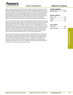
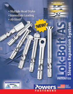

© Copyright 2026