
Primary Superior gyratory crushers
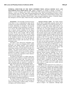
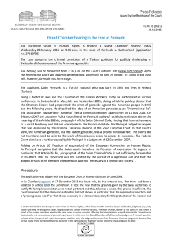
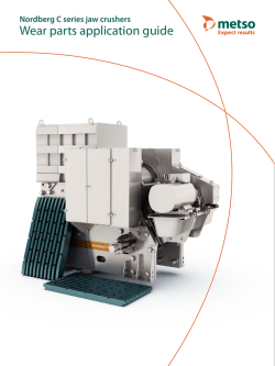
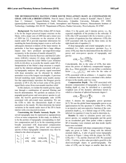
Expect results
Metso’s Mining and Construction Technology
SUBJECT TO ALTERATION WITHOUT PRIOR NOTICE. BROCHURE NO. 2761-06-12-SBL/TAMPERE- ENGLISH ©2012 METSO
Expect results is our promise to our customers and
the essence of our strategy. It is the attitude we share
globally. Our business is to deliver results to our
customers, to help them reach their goals.
Primary SUPERIOR® gyratory crushers
Wear parts application guide
Wear parts application guide - SUPERIOR® gyratory crusher
Gyratory crusher and basic concepts
The SUPERIOR® gyratory crusher
is a compressive style crusher for
primary-stage applications. Its
steep crushing chamber and
long crushing surfaces provide
exceptionally high capacity and
long liner life.
A gyratory crusher consists of a concave surface and a conical head; both surfaces are
typically lined with manganese steel. The top
of the shaft attached to the crushing cone is
supported centrally in the bushings, and the
bottom of the shaft is positioned in an
eccentric bushing.
The feed material is crushed between the
fixed concave surface and a movable mantle.
The bigger rock material is crushed against
the mantle and the concave.
The crushing action is caused by the closing of the gap between the moving mantle
liner mounted on the central vertical shaft
and the fixed concave liners mounted in the
top shell of the crusher. The gap is opened
and closed by an eccentric assembly in the
bottom shell, which causes the central vertical shaft to gyrate. The vertical shaft is free to
rotate about its own axis.
Gyratory crushers are one of the main primary crusher types used in mines and quar2
ries. The size designation of gyratory crushers
is based on the size of the feed opening and
the mantle diameter.
Main features
• Steep crushing chamber and long crushing surfaces for exceptionally high capacity and maximum liner life
• Extra heavy-duty frame, integral largediameter mainshaft assembly, and high
performance bearing arrangement provide long life and reliable operation
• Accurate crushing chamber design for
optimized production
• Dual counterbalance design minimizes
the dynamic forces transmitted to the
supporting structure
• Large-diameter mainshaft upper journal
with threaded, replaceable alloy steel
sleeve
• Hydraulically operated and controlled
mainshaft positioning system for quick
and effective adjustment of the mainshaft
to compensate for liner wear
• Easy maintenance and service
Spider CAP
Spider
ARM
shield
Spider
RIM liners
Top shell
assembly
Mainshaft
assembly
Pinionshaft
assembly
Eccentric
assembly
Mainshaft
positioning
system assembly
Current model sizes
Recognized as the world leader, Metso
Mining and Construction Technology offers
the complete range of primary gyratory
crushers to meet all application requirement.
Machine size*
Feed opening
mm (in )
Mantle diameter
mm (in)
42-65
1065 (42)
1650 (65)
50-65
1270 (50)
1650 (65)
54-75
1370 (54)
1905 (75)
62-75
1575 (62)
1905 (75)
60-89
1525 (60)
2260 (89)
60-110
1525 (60)
2795 (110)
Open side setting
The superior gyratory crusher’s discharge
setting is referred to as the Open Side
Setting (OSS).
This is a single pre-determined setting at
which the crusher and it’s crushing chamber
are designed to operate. The setting cannot
be operationally changed to produce different product sizes instead the setting change
is made by modifying the bottom tier of the
concave.
*1st number = feed opening in inches,
2nd number = mantle diameter in inches
Spider design
Metso’s primary gyratory crusher range
includes 4 basic head sizes (65”, 75”, 89” and
110”), in addition to which the Super Spider
upgrade provides two additional larger feed
openings.
The patented U-shaped spider arms (currently available on the 60-110E) reduce twisting during crushing. Arched spider arms create a less restricted feed opening to reduce
material bridging.
C.S.S
Mainshaft positioning system
The mainshaft position system is a hydraulic
method of vertical adjustment to compensate wear. It consists of a pump, controlled
by a push-button, and a heavy-duty hydraulic cylinder that supports and adjusts the
position of mainshaft assembly.
• In lowest position with a new mantle and
new concaves, there is about 1” (25mm)
of oil under the piston
• In highest position the minimum distance
between the head nut and the spider is 1”
(25mm)
The mainshaft positioning system is only
used to compensate mantle and concave
wear, not to change the crusher setting. The
Superior Gyratory Crusher is designed for
one setting only with a given set of concaves.
O.S.S
O.S.S. - C.S.S. = Eccentric throw
3
How to operate a gyratory crusher
Operating a Gyratory Crusher
within its design parameters
reaps huge benefits for the enduser, most notably, maximum
crusher online availability, lowest
possible maintenance repair
costs, improved productivity and
maximized crusher life span.
In order to achieve these benefits, the following should be
considered:
1. Always start the crusher correctly
• Verify that the tank oil temperature is
between 86°F (30°C) and 90°F (32°C)
• Start the lube pump and circulate the oil
• Start the crusher drive motor and allow
the crusher to come to full speed
• Run the crusher with no load (empty) until
the return oil temperature is above 65°F
(18°C)
• Start feeding the crusher
2. Ensure proper pinionshaft speed
• If the pinionshaft speed is much below
the recommended RPM, the crushing performance can be adversely affected and
can cause the crusher to stall
• If the pinionshaft speed is much above
the recommended RPM, the crusher bal4
ance and lube oil cooling can be adversely
affected
3. Monitor no-load head spin
• In most cases, no-load head spin will be
20 RPM or less. An excessively worn spider
bushing can cause high no-load head spin
• Monitor head spin at normal oil temperature. Normal oil temperature is in the
range of 100ºF (38ºC) to 115ºF (46ºC) with
ISO VG 68 EP2 oil or 100°F (38°C) to 130°F
(54°C) with ISO VG 150 EP4 oil
4. Operate within the design limits
• Volume limit:
Each crushing chamber (mantle and concaves) has a volume limit which determines maximum throughput. A full crushing chamber is operating at its volumetric
limit
• Do not exceed the maximum feed size.
Attempting to crush oversize feed material
wastes time and reduces crusher capacity.
The maximum feed size should be less
than 80 – 85% of the nominal feed opening. This size distribution helps prevent
blockage at the spider opening and allows
a well-filled crushing chamber that will
evenly distribute the crushing forces
• Power limit:
Power consumption will vary based on
the crushing chamber used and the
eccentric throw: increased throw =
increased power draw. The power limit is
exceeded if the crusher drive motor draws
more power than it is rated for (the
attached power must be compatible with
the actual throw being used in the crusher).
5. Keep the overloading frequency to a
minimum
Overloads affect productivity and crusher
reliability. Overloads can be caused by:
• Tramp material (steel, wood, plastic,
rubber, etc.)
• High moisture content of the feed
material
• Sticky feed materials
• Crusher set too tight for conditions
• Improper feed arrangement to the crusher
• Crusher fitted with the wrong style of
mantle and concaves
Note: For new installations the chamber performance and wear profile
must be determined for the target
application in order to ensure optimal
material choices and develop the
most economical customer solution.
Changes in ore size and ore properties also affect chamber performance
so a system survey aimed at developing an optimal chamber solution may
be required.
5
SUPERIOR® chamber
The crushing chamber, also
known as the crusher cavity, is
composed of a mantle and
concave segments.
The Superior crushing chamber is designed
for a specific open side setting (OSS) which
is tailored for each individual application.
The concave profiles are designed taking
into account the optimal combination of nip
angle, power draw, crushing force and
capacity requirements. The required product
output size is achieved with the design of
the lower tier concaves (O.S.S). A reduced
throw eccentric can be supplied to reduce
crusher throughput and therefore allow a full
chamber to be maintained which will produce a more consistent product with less
oversize material.
The objective is to maximize crusher productivity and to achieve best possible wear
material performance. The unique SUPERIOR
crushing chamber concept provides:
• Even wear
• Greater product uniformity
• Better distribution of wear throughout the
chamber – fewer service problems and
lower operating cost
• Fewer liner changes – less wear costs per
product ton
• Improved energy efficiency
6
High abrasion resistance concaves
• Single or double tier concaves available in
a variety of alloys
• Secured manufacturing / casting / heat
treatment process
• Easy to fit. Special concaves are preassembled before delivery and equipped with
v-groove for thickness monitoring and
predictive maintenance.
• Cost effective. Extended wear life and
application-specific liners
• No maintenance, no gouging
• No swelling – growth. Reduced downtime
• Reduced risk of fall out with locking
system. Conical pins or lock bars
V-groove
Backing material
The backing material fills the void between
the concaves and shells or the mantle and
head to provide a solid assembly. Metso
offers WF Ultra Performance backing material for long-lasting and secure installation.
Examples of single tier (left) and double tier (center) chambers. Chamber segment thickness (right) varies depending on the application.
Concave segments
MIDDLE CHAMBER
LINERS (MID)
XT510 / XT525
XT610 / XT710
Low-alloy steel,
High-chrome special
●●
●●●
●●●
●●
●●
●●●
●●●
●●
●●
●●●
●●●
●●
C
C
C
C
C
C
●●
●●●
●●
●●●
●●
●●●
●●●
●●
●●
●●●
●●●
●●
C
C
C
C
C
C
●
●●
●●●
●●
●
●●
●●●
●●
C
●●●
C
s
liner
er in
take
Upp
rs
Easy and
non abrasive
r line
Easy and
abrasive
BOTTOM CHAMBER
LINERS (BTM)
●
●●●
XT510 / XT525
●●
●●
XT710 / XT810
Low-alloy steel,
●●● (C)
C
High-chrome special
● Can be used ●● Good choice
●●● Recommended
C - Contact Metso representative for more information
●●●
Bottom tier high wear
resistant liners
XT510 / XT525
XT610 / XT710
Low-alloy steel,
High-chrome special
Difficult and Difficult and Medium and Medium and
abrasive non abrasive abrasive non abrasive
Midd
UPPER INTAKE
LINERS (TOP)
Upper Intake Liners
• Manganese alloys
• Low-alloy steel, impact resistant
Chamber Mid Liners
• High manganese alloys
• Low-alloy steel, abrasion and impact resistant
Chamber Bottom Liners
• Low-alloy- steel, high abrasion and impact
resistant
• High-chrome special, maximum abrasion
resistance
amb
e
Metso’s standard concave alloy is manganese, but depending on the feed characteristics a variety of other alloys can be chosen
to achieve best cost per produced ton. The
upper concave tiers must withstand high impact forces. The lower tiers require maximum
abrasion resistance
le ch
Material selection
Definitions for different rock types are presented
in Wear and materials application guide, page 4.
7
Mantle options
Different alloys, designs and
sectioned mantles can be selected to achieve the best cost per
produced ton, depending on the
application and the wear rate.
Choosing the correct mantle is always an
application-specific process. The following
mantle designs are available or will be
designed to meet the customer’s process
requirements:
• 1, 2 and 3 piece
• Smooth, partially corrugated, fully
corrugated
• Undersize, standard, oversize #1, #2
• Matched mantles, RBD #1 and #2
• Special application-specific designs
Model
1 Piece
2 Piece
3 Piece
42-65
50-65
54-75
62-75
60-89
60-110
Standard
Optional
Standard
Optional
Optional
Optional
Standard
Optional
Standard
Standard
Standard
Optional
Optional
Approximate weight of shaft
( complete assembly )
42-65
50-65
54-75
62-75
60-89
60-110
8
51 000 lbs. (23 130 kg.)
62 000 lbs. (28 120 kg.)
85 000 lbs. (38 560 kg.)
93 000 lbs. (42 180 kg.)
146 000 lbs. (66 220 kg.)
226 160 lbs. (102 585 kg.)
Mantle size
For each primary gyratory model there are
several basic mantle sizes: standard, undersize and oversize. Oversize mantles can be
used, for example, to maintain the primary
gyratory’s setting during concave wear.
Undersize mantles are needed if extra thick
concaves are used.
For perfect fitting of the mantle, the bottom skirt diameter can also be modified (see
‘Matched mantles‘, page 9.).
In addition, Metso offers fully customized
designs for special applications.
Sectioned mantles
During operation the primary gyratory’s
wearparts are subject to shock and impact
loads in the upper chamber, abrasive wear in
the bottom of the chamber and a combination of these in the middle part of the chamber. When using a 2 or 3 piece mantle, best
performance can be obtained by selecting
optimal material characteristics for each
mantle piece according to the target application. However, 1 piece mantle is faster to
change and 2 or 3 piece mantle may not be
suitable for all applications.
Smooth and corrugated designs
The first choice of mantle design is either
smooth or partially corrugated. Two corrugated profiles are available: partially and fully
corrugated.
The smooth mantle design is an ideal
choice for high abrasive applications.
Depending on the application properties,
the corrugated profile may provide better
performance. A corrugated surface effectively removes fines from the mantle surface,
provides better grip on the feed material and
reduces mantle material expansion. The fully
corrugated design is for special applications
only.
Examples of smooth (left), partially corrugated (center)
and fully corrugated (right) mantle profiles.
Matched mantles
The mantle should fit easily through the
smallest inner diameter of the chamber during installation or replacement. It is important to know what concaves are used in
order to be able to match the mantle bottom skirt diameter.
Matched mantles are called RBD (Reduced
Bottom Diameter) mantles. It is important to
note that the RBD is NOT the actual mantle
size. An RBD is, for example, a modification
of an oversize mantle made in order to fit
through the concave’s smallest inner diameter.
Material selection
The first choice of material for standard mantles is the XT510. To further maximize performance and wear life, special designs and
high-alloy options are also available. Please
consult your Metso representative for more
information.
MANTLE MATERIALS
XT510/XT515/XT520/XT525
XT710
XT750 / XT810
● Can be used
Difficult and Difficult and Medium and Medium and
abrasive non abrasive abrasive non abrasive
●
●●
●●● (C)
●● Good choice
●●●
●●● Recommended
C - Contact Metso representative for more information
●
●●
●●● (C)
●●●
●
Easy and
abrasive
Easy and
non abrasive
●●
●●●
●●●
●●
C
Definitions for different rock types are presented
in Wear and materials application guide, page 4.
9
10
Legal notice
Metso reserves the right to make changes to
specifications and other information
contained in this publication without prior
notice. The reader should in all cases consult
Metso to determine whether any such
changes have been made. This manual may
not be reproduced and is intended for the
exclusive use of Metso customers.
The terms and conditions governing the sale
of Metso hardware products and the
licensing and use of Metso software
products consist solely of those set forth in
the written contract between Metso and its
customer. No statement contained in this
publication, including statements regarding
capacity, suitability for use, or performance
of products, shall be considered a warranty
by Metso for any purpose or give rise to any
liability of Metso.
In no event will Metso be liable for any
incidental, indirect, special, or consequential
damages (including lost profits), arising out
of or relating to this publication or the
information contained in it, even if Metso
has been advised, knew, or should have
known of the possibility of such damages.
Metso, 2012. All rights reserved.
11
© Copyright 2026