
2191
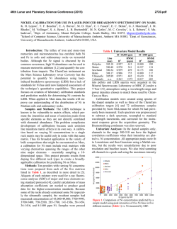
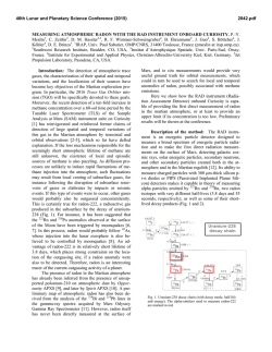
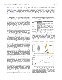
46th Lunar and Planetary Science Conference (2015)
2191.pdf
PIEZOELECTRIC DUST DETECTOR DESIGN AND CALIBRATION FOR THE ARMADILLO
PROGRAM. F. Odom III1, G. Richter1, J. Brown1, B. Martinsen1, R. Cai1,4, M. Fellows1, A. Wolf1,2, C. Montag1,5,
P. Young1, J. A. Carmona-Reyes1, J. Schmoke1, M. Cook1, B. Garner4, I. Gravagne4, K. Pin1, L. Shedd1, T.
Groskreutz1, T. Hegle1, N. Mulenos1, J. Stone1, C. Wiley1, V. Yanga1, D. Eustice1, K. Flachsbart1, N. Steele1, C.
Tilley1, P. Friudenberg1, D. Penshorn1, L. Henderson1, E. Cavazos1, A. Nabili1, E. Cox1, A. Cox1, J. Wood1, L.
Devine1, J. Curran1, A. Mendiola1, C. Falkner1, R. Laufer1,2, R. Srama1,2, K. E. Schubert4, L. S. Matthews1, G Lightsey3 and T. W. Hyde1, 1CASPER (Center for Astrophysics, Space Physics and Engineering Research), Baylor University, Waco, TX 76798, [email protected]. 2Institute of Space Systems, University of Stuttgart,
Raumfahrtzentrum Baden-Württemberg, Pfaffenwaldring 29, 70569 Stuttgart, Germany 3Space Systems Design
Laboratory, Georgia Tech University, Atlanta, Georgia 30332. 4Department of Engineering, Baylor University, One
Bear Place #97356, Waco, TX 76798-7356, USA. 5Institute of Aerospace Engineering, Technical University of
Dresden, Marschner Strasse 32, 01062 Dresden, Germany.
Introduction: ARMADILLO (Attitude Reference
Maneuvers And Debris Instrument in Low Orbit) is a
CubeSat currently slated to fly either April 2015 or
January 2016. Armadillo is being built in partnership
between Baylor University and the University of Texas
at Austin and is funded by the University Nanosatellite
Program (UNP), which is sponsored by the US Air
Force. ARMADILLO’s primary science experiment is
a Piezoelectric Dust Detector (PDD), which is being
built by Baylor University’s Center for Astrophysics,
Space Physics, and Engineering Research (CASPER).
Once on orbit, ARMADILLO will be the first CubeSat
to monitor in-situ space debris [1].
PDD Design, Calibration and Testing:
ARMADILLO and the PDD will be placed in LowEarth Orbit (LEO) at an altitude of about 400 km,
comparable to that of the International Space Station.
At this altitude, there is a large amount of man-made
space debris due to past satellites that were either destroyed or displaced once they were no longer functional [2].
Hardware Design: The PDD is comprised of two
primary components. The Main Detector Unit (MDU)
(fig. 1) consists of nine PZT sensors and two wire grids
with the top grid of the MDU acting as both protective
shield and ground. The second grid is charged providing a signal based on the charge produced by the vaporized dust particles. The Secondary Detector Unit
(SDU) (fig. 2) is similar but consists of only a single
PZT plate sensor, which is mounted on the side of the
satellite towards the zenith. Both the MDU and SDU
receive power and command instructions from the
ARMADILLO satellite; the satellite in turn relays impact data to ground stations for processing and analysis.
Software Design: The control software employed
handles housekeeping communication with the primary
CPU, data transmission and event detection. A key part
of the software programming for this design is to establish a microprocessor structure on the FPGA, which
will be used primarily for communicating with the
satellite's computer.
Figure 1. The PDD employs ten PZT plates—nine arranged in a 3-by-3-grid array (the Main Detector Unit
or MDU and one on the Secondary Detector Unit or
SDU).
Figure 2. Stand-alone PZT plate used in the Secondary
Detector Unit (SDU), which will be placed on the side
of the ARMADILLO CubeSat facing the zenith.
Initial Calibration: Initial bench–testing for the
PDD was conducted employing a drop tower. Aluminum and stainless steel impactors were used in the
calibration process with data captured via LabVIEW
(fig. 3).
Figure 3. Drop tower setup for typical 9 channel impact data collection. Each PZT is connected to a different channel on one of the three oscilloscopes shown.
The data collected suggests the PDD should be able to
withstand representative space debris impacts (with
velocities determined using the Debris Assessment
46th Lunar and Planetary Science Conference (2015)
Software suite - DAS version 2.0.2) over the predicted
orbit [3]. It also will allow proper analysis of in-situ
data. Prior to launch, additional calibration runs will be
conducted using CASPER’s light gas gun [4].
2191.pdf
raw data and data collected by the PDD onboard computer. Fourier analysis of this data showed a resonant
Figure 4. PDD vacuum test. This initial test lasted 9.5
hours while thermistors placed in key sections of the
PDD were monitored.
Thermal testing: A thermal stress test was conducted to determine whether the PDD would function
properly under near Earth space environmental conditions (i.e. 1×10− 2 Torr or lower), where it becomes
much more difficult for heat to dissipate from the system (fig. 4). Under normal temperature and pressure
conditions, the PDD electronics were operated at full
power over an extended period of time. Using an infrared camera, sixteen “hot-spots” were identified on the
various electronics boards. Subsequently, the PDD
was operated at 10 mTorr with thermistors placed at
each “hot-spot” location while the PDD was brought to
full power. Temperatures were collected across all 16
channels at three-second intervals over a period of 9.5
hours. The highest temperature reading on any one
channel corresponded to the channel monitoring the
memory chip; after two hours of run time, this temperature stabilized at 51 degrees Celsius (well below the
maximum operational temperature for the chip), where
it remained for the remainder of the experiment.
Data Analysis: As impactor energy increases, the
transferred energy deforms the PZT, producing an
electrical charge due to the piezoelectric effect. Depending on velocity, a linear relationship will exist
between the impact energy of the impactor and the
PZT voltage, up to mechanical and electrical limits.
Representative data for this process is shown in figure
5. For the proposed orbit, DAS 2.0.2 predicts the PDD
will primarily observe µm space debris (at 10 km/s)
having an energy range of 2 × 10− 7 J to 3 × 10⁻⁴ J. In
order to properly analyze the in-situ data collected by
the PDD, all nine PZTs within the MDU should register a calibrated signal. In order to establish this calibration, raw data from the drop tower (as collected by the
oscilloscopes) was modeled as a damped harmonic
oscillator:
V (t) = A e− βt sin[ωt + φ]
Where β represents the decay constant of the signal.
An independent decay constant for each set of data was
extracted in order to allow comparison between the
Figure 5. Typical response of the MDU PZT matrix. V is peak-to-peak voltage, E is the impact energy.
frequency of 98 kHz and a decay constant of 5000 as
compared to the PDD onboard computer data which
showed a resonant frequency of 110 kHz and a decay
constant close to 5000. The difference in these results
may be attributed to the difference in sampling rates
between the oscilloscopes employed and the PDD.
(The oscilloscope-sampling rate is 2.5 MHz while the
PDD sampling rate is 1 MHz). To a first order of approximation, these results provide high enough precision to assess impact magnitudes and determine PZT
plate integrity through monitoring of the resonant frequency shift and changes in decay constant magnitude.
Conclusions: Initial tests and unit calibration have
been conducted to identify all necessary PDD characteristics. Using these results, impact energies of in-situ
space debris can be predicted through measurement of
the peak-to-peak voltage, as defined by the linear fit
model presented here (see fig. 5). It has also been
shown that this signal can additionally be characterized
using Fourier analysis and nonlinear modeling to extract vibrational frequencies and decay constants, respectively. The same signal analysis techniques will
be used to estimate space debris collision and determine PZT plate integrity. Finally, it has been shown
that the PDD should survive space conditions without
excessive thermal stress to any of its components.
References: Brumbaugh, K. M., Kjellberg, H. C.,
Lightsey, E. G., Wolf, A., Laufer, R. (2012). Advances
in the Astronautical Sciences. [2] Shell, J. R. (2010)
DTIC Document. [3] Opiela, J. N., Hillary, E., Whitlock, D. O., & Hennigan, M. (2007). Astromaterials
Research and Exploration Science Directorate, Orbital
Debris Program Office. [4] Carmona-Reyes, J., Cook,
M., Schmoke, J., Harper, K., Reay, J., Matthews, L., &
Hyde, T. W. (2004) 35th COSPAR Scientific
Assembly, 35, 794.

© Copyright 2026