
nuim.ie
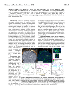
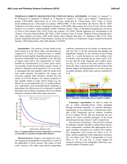
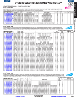
Impact of Time-interleaved Analog-to-Digital Converter
Mismatch on Digital Receivers
Michael Soudan∗ , Ronan Farrell†
Center for Telecommunications Value Chain Research
Institute of Microelectronics and Wireless Systems
National University of Ireland, Maynooth, Co Kildare
Email: ∗ [email protected], † [email protected]
Abstract— This paper presents the impact that gain, offset and timing
mismatch in time-interleaved analog-to-digital converter (TIADC) have
on digital receiver systems. An analysis of the mismatch errors shows
the dependency of the different errors from the spectrum of the input
signal. A discrete-time TIADC model is derived allowing to simulate
the mismatch effects of the individual ADCs. Finally, simulations results
present the performance degradation that can be expected by the usage
of non-ideal analog-to-digital converters (ADC) sampling alternately
the inphase and quadrature signals in a direct conversion receiver
architecture when random data is processed.
from the ideal sampling instant caused by clock skew and different
circuit response times. This paper will present an analysis of these
error mechanims and their impact on the performance of a radio
receiver, methods for minimising these effects, and conclude with
some guidelines for system designers on the use of time-interleaved
ADCs.
I. I NTRODUCTION
An important figure of merit for ADCs is the signal-to-noise ratio
(SNR) describing the signal power relative to the noise power in
Decibel (dB), i.e.
A trend in the design of digital communication systems is
to minimise the analog components in favour of digital signal
processing, as typified by the software-defined radio concept [1].
This requires the analog-to-digital converter (ADC) to move towards
the antenna in the receiver chain, demanding ever increasing
performance. Though a direct analog-to-digital conversion after the
antenna would be favorable in terms of receiver flexibility, the
required ADC performance is far beyond todays state-of-the-art
technology. A compromise between the all-digital and the traditional
processing can be achieved by using receiver architectures such as
the low-IF and direct conversion architectures. However the ADC
is seen as one of the most challenging components for such radio
systems demanding high resolution, high sampling rates and low
power consumption.
The need for high ADC resolution can be demonstrated by
examining the sensitivity requirements of radio, where it is necessary
to detect a small communications signal in the presence of strong
blocking signals and background noise. The ADC resolution has to
be sufficient to convert a weak signal while the interfering signals
occupy the full input range of the ADC. A common metric to assess
the receiver performance is the symbol error rate (SER) of the system,
specifing the ratio of wrongly detected symbols to the overall number
of symbols. The second important ADC parameter is the minimum
sampling rate. This is determined by the input signal bandwidth [2].
As more broadband wireless services are developed, the input signal
bandwidths are increasing, for example IEEE 802.16e (WiMAX) has
an option for a 25 MHz channel requiring a sampling rate in excess
of 50 MSps [3]. A high resolution ADC with this sampling rate
is expensive. One promising technique for providing this level of
performance is through the use of multiple time-interleaved ADCs
(TIADC) [4]. While time-interleaving enables the designer to improve
the operall sampling system quite easily, a degradation of the spectral
purity is caused by the dissimilar characteristics of the individual
ADCs. In particular, gain, offset and timing mismatch between
the individual ADCs causes spurious tones in the output spectrum
of the TIADC thereby degrading the spurious free dynamic range
(SFDR) of the system. The term timing mismatch refers to a constant
deviation, as opposed to random variations, of the sampling process
II. T IME -I NTERLEAVED A NALOG - TO -D IGITAL C ONVERTER
snrdB = 10 log
2
1/N ∑N−1
k=0 x(n)
2
1/N ∑N−1
k=0 e(n)
(1)
Alternatively, the signal-to-noise can be indicated by using
effective number of bits to show the effective resolution of the ADC
in the presence of noise.
snrenob =
snrdB − 1.76dB
6.02dB/bit
(2)
To analyse the performance of a system using several ADCs in
parallel, a mathematical model is required as shown in (3) [5], where
M represents the number and m the index of the individual ADCs.
The gain and offset of the ADCs is indicated by the variables ∆g and
o. The error ∆t is defined as the timing error relative to the sampling
period Ts which represents the sampling period of the overall timeinterleaved system. It describes deviation of the sampling process
from the ideal sampling instant. Therefore, the output y(t) can be
described as
∞
y(t) =
M−1
∑ ∑ ((1+∆gm )(x(t +∆tm )+om ))δ(k −kMTs −mTs )
(3)
k=−∞ m=0
Normally this equation would be analysed with the assumption
of a sinusoidal input, thereby allowing the derivation of the TIADC
frequency spectrum (see [5]). Hoever, it is possible to simplify the
calculation by estimating the effect of timing mismatch by a firstorder linear interpolation.
∞
y(t) =
M−1
∑ ∑
(1 + ∆gm )(x(t) + x(t) ∆tm ) + om δ(k −kMTs −mTs )
k=−∞ m=0
(4)
The multiplication in the time domain can be represented by
the convolution in the frequency domain and the TIADC spectrum
becomes
Y ( jΩ) =
∞
1
∑
MTs k=−∞
M−1
∑ ((1 + ∆gm )(X( jΩ) + jΩ X( jΩ)∆tm )
(5)
m=0
Ωs − jkm2π/M
)e
M
Rearranging the terms of (5) shows the undesired signal parts of
the individual channel spectrum, i.e.
+om ) δ(Ω − k
Y ( jΩ) =
∞
1
∑
MTs k=−∞
M−1
∑ (X( jΩ)(1 + ∆gm + (1 + ∆gm ) jΩ∆tm )
(6)
m=0
Ωs − jkm2π/M
)e
M
Equation (6) shows that the gain and timing error terms are the
replica of the input signal but with the scaling factors gm and
(1 + ∆gm ) jΩ∆tm respectively. Since the timing mismatch term is
multiplied with j, it can be concluded that the corresponding error
signal of each channel is 90 degree out-of-phase with respect to
the input signal and gain error. However, the offset term in (6)
is independent of the input signal spectrum and acts as a channel
dependent DC offset as had to be expected. Therefore, this error
becomes a dominant part of the error specturm for weak input signals
since the power of the other error spectra declines for decreasing input
signals.
These insights give us the opportunity to calculate the overall signal
power out of the power of the dc offsets, in-phase and quadrature
phase components for arbitrary input signals. This results in (7) for
the mismatch power of a single channel m, i.e.
+om ) δ(Ω − k
Pm = om 2 + Ptm + Pgm
(7)
The mismatch power of the time interleaved system is given by
the following equation.
PT I =
M−1
1 M−1 2 M−1
( ∑ om + ∑ Ptm + ∑ Pgm )
M m=0
m=0
m=0
(8)
This equation describes the mean squared error of the non-ideal
signal relative to the ideal sampling instants.
III. T RANSCEIVER M ODEL
To simulate the impact that gain, timing and offset errors have
on the TIADC spectrum, an idealised discrete-time transceiver
model was derived. As a modulation scheme quadrature amplitude
modulation (QAM) was selected due to its wide-spread use in current
and emerging technologies. This model accounts for the transmitter
side zero-padding to increase the number of samples per symbol,
root raised cosine shaping of the inphase and quadrature (I/Q)
pulses and the impact of white Gaussian noise on the channel. The
transmitter zero-padding eases timing synchronisation on the receiver
side augmenting at the same time the bandwidth requirements of the
I and Q channel ADCs.
The time-interleaved model comprises gain and offset factors and
a fractional finite impulse response (FIR) filter for each individual
ADC. Fractional delay filters are non-causal filters that allow the
delaying of signals by a fraction of the sampling period. The finitelength implementation of such a filters suffers from ripples that can
be attenuated by using a windowing function. However, windowing
functions do not reduce the overall mismatch energy but shifts the
error to higher frequencies. The causal impulse response of an even
Fig. 1.
QAM transceiver model.
order fractional delay of length N windowed by a shifted Hann
window is given by (9), where n = 0..L − 1.
hFD (n) = 0.5sinc(n + D −
N −1
2π
)(1 − cos(
(n + D)))
2
N −1
(9)
IV. S IMULATION R ESULTS
The model presented in section III has been simulated using 1000
uniformly distribued data points as an input signal for the quadrature
amplitude modulator. The kernel lengths of the root raised cosine
filters were given by 32L + 1, where L indicates the zero padding
factor. The filter kernels of the utilized fractional delay filters were
of the order 120 and multiplied with a shifted Hann window. The
receiver TIADCs of I and Q channel comprised two ADCs each
affected by a random gain, offset and timing error to account for
the non-ideal ADC characteristic. These individual ADC errors were
selected using a Gaussian distribution according to its given standard
deviation. The full-scale range of the time-interleaved ADCs were
determined by the peak-to-peak amplitude of the I respectively Q
channel. The demodulated receiver output was compared with the
delayed input signal of the transmitter and the mean squared error
was calculated. The presented results in this section show the average
value of 500 simulations to provide statistical significance.
Gain and offset error values refer to the full-scale range of the
ADC, whereas the timing mismatch refers to the relative deviation
from the TIADCs sampling period, i.e. ∆t = tv /Ts , where tv is the
absolute value of the timing mismatch. 16 bit ADCs are used in the
time-interleaved system, unless stated otherwise.
Fig. 2 shows the mean squared error ratio of the I/Q channel data to
the periodic mismatch noise. It is interesting to notice how the impact
of timing mismatch declines with increasing zeropadding factor L.
This factor controls the oversampling of the signal from an ADC
point of view. Therefore, the normalized bandwidth given by the
ratio of signal bandwidth to sampling rate, decreases with increasing
L. For a constant relative timing mismatch error ∆t, this results in a
decreasing timing mismatch mean square error, as can be seen in (6).
This result is consistent with the TIADC results stating that the timing
mismatch power rises with increasing signal to sampling frequency
ratio [5].
Gain as opposed to timing error only depends from the input spectrum
but not from the sampling frequency. Therefore, increasing zeropadding only changes slightly the signal shape which has only little
impact on the mismatch power.
A similar dependency to Fig. 2 is shown in Fig.3, where the impact
of mismatch on QAM modulation with different alphabet sizes is
16 QAM
16 QAM; L=2
110
18
100
16
14
80
snr (enob)
Pc / PTI (dB)
90
70
60
50
40
−4
10
10
8
∆ g; L=2
∆ t; L=2
∆ t; L=3
∆ t; L=4
−3
12
−2
10
10
mismatch std. deviation σ
∆g
∆t
o
4
∆ g, ∆ t, o
2
−4
10
−1
10
Fig. 2. Mismatch power of a 2-channel TIADC relative to the random inphase
data signal.
6
−3
−2
10
10
mismatch std. deviation σ
10
−1
Fig. 4. Signal-to-noise ratio in ENOB over the standard deviation of the
mismatch errors for 16 QAM and zero- padding of 2
4 QAM & 64 QAM; L=2
110
of these errors are given as 5%, 0.5 % and 5%. The 4 QAM system
is hardly affected by the mismatch of the TIADCs due to the great
Euclidean distance of its constellation points. However, an increasing
number of constellation points in combination with the mismatch
errors increases the symbol error rate of the system, as can be seen
from the 16 and 64 QAM modulation systems.
100
80
4, 16, 64 QAM; L=2
70
60
50
40
−4
10
64 QAM
∆ g; 4 QAM
∆ t; 4 QAM
∆ g; 16 QAM
∆ t; 16 QAM
−3
−1
10
−2
10
10
mismatch std. deviation σ
16 QAM
−1
10
ser
Pc / ∆ P (dB)
90
4 QAM
−2
10
Fig. 3. Mismatch power of a 2-channel TIADC relative to the random inphase
data signal.
−3
10
depicted. The degradation of the effective resolution of the TIADC
caused by gain, timing mismatch, offset and the combination of all
three mismatch types is shown in Fig. 4. The graph marked by squares
depicts the combination of all three errors, where the standard of all
errors is of equal magnitude. It is interesting to notice that the SNR
performance for small mismatch error magnitudes exceeds the 16 bit
performance of the individual ADCs. This can be explained by the
low pass characteristic of the root raised cosine filter attenuating the
noise in half of the Nyquist bandwidth for an oversampling of two
(L = 2). This results in an SNR improvement of approximately half
a bit of effective resolution. The mismatch errors degrade the ADC
performance severely for mismatch values greater than 0.1 %, as can
be seen from Fig. 4.
Fig. 5 shows the symbol error rate of the transceiver model using
4, 16 and 64 QAM. The dashed lines indicate the symbol error
performance over Eb /N0 , where the TIADC is not affected by any
mismatch errors. The solid lines show the impact of gain, offset and
timing mismatch error on the SER. The respective standard deviations
0
5
10
15
Eb/No (dB)
20
25
Fig. 5.
Symbole error rate over Eb /N0 for 4, 16 and 64 QAM with
(solid lines) and without mismatch errors (dashed lines) ([∆g, ∆t, o] =
[0.05, 0.005, 0.05])
V. C ONCLUSION
In this paper, we have analyzed gain, offset and timing
mismatch errors in time-interleaved ADCs. We have derived formulas
demonstrating the dependencies of the mismatch errors from the
spectrum of the input signal. To simulate the impact, the mismatch
errors have on the performance of a digital receiver, a discrete-time
model has been derived. The performance degradation of a digital
receiver utilizing time-interleaved ADCs has been shown for different
quadrature amplitude modulation schemes and oversampling ratios.
Simulations have been presented indicating that small mismatch
errors deteriorate the effective resolution of the time-interleaved
ADC, when root-raised-cosine shaped random data is processed. It
has been shown that ADC mismatch severly increases the receiver
symbol error rate for higher order quadrature modulation systems,
whereas it has little impact on low order systems.
ACKNOWLEDGMENTS
This work has been carried out as the part of Science Foundation
Ireland supported Center for Telecommunications Value Chain
Research at the Institute of Microelectronics and Wireless Systems,
National University of Ireland, Maynooth, Co. Kildare.
R EFERENCES
[1] J. Mitola, Software radios: Survey, critical evaluation and future
directions, IEEE Aerospace and Electronic Systems Magazine, vol.8, pp.
25 - 36, 1993.
[2] H. Nyquist, "Certain Topics in Telegraph Transmission Theory",
Proceedings of the IEEE, vol.90, pp. 280-305, 2002.
[3] IEEE, IEEE Std 802.16-2004, IEEE Standard for Local and Metropolitan
Area Networks, Part 16: Air Interface for Fixed Broadband Wireless
Access Systems, 2004.
[4] W. Black, Time interleaved converter arrays, IEEE Journal on Solid-State
Circuits, vol.8, pp. 1022 - 1029, 1980.
[5] C. Vogel, The Impact of Combined Channel Mismatch Effects in
Time-Interleaved ADCs, IEEE Transactions on Instrumentation and
Measurement, vol.54, pp. 415 - 427, 2005


© Copyright 2026