
Study of Stability of Precise Tiled-grating Device
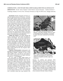
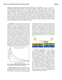
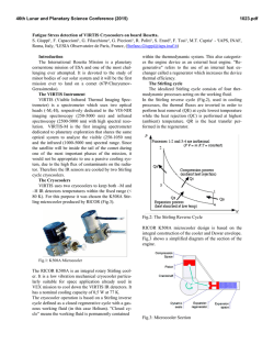
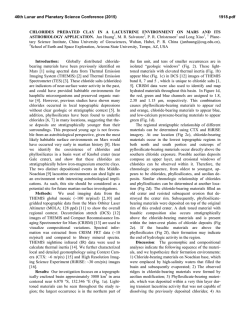
Strojniški vestnik - Journal of Mechanical Engineering 61(2015)2, 99-106 © 2015 Journal of Mechanical Engineering. All rights reserved. DOI:10.5545/sv-jme.2014.1658 Received for review: 2014-01-09 Received revised form: 2014-08-22 Accepted for publication: 2014-10-17 Original Scientific Paper Study of Stability of Precise Tiled-grating Device Yunfei, L. – Yi, Z. – Youhai, L. – Dong, Z. – Bo, T. Liao Yunfei – Zhou Yi* – Liu Youhai – Zuo Dong – Tan Bo College of Mechanical Engineering, Chongqing University, China To satisfy the high-stability requirement of a tiled grating, we have analyzed and optimized the stability of a newly designed precise tiledgrating device considering three aspects: structure design, transmission chain, and control algorithms. The main structure of the device is changed from a parallel-board structure to a new tetrahedral brace design, enhancing the overall vibration stability; during the analysis of the transmission chain, the adjustment accuracy and stability of the device were ensured by slowing the growth of the error transmission factor; and for the optimization analysis of the PID control algorithms, we adopted a latch compensation method to avoid the saturated loss and a four-point central difference method to avoid the disturbances, thus enhancing the stability control of the device. To test the stability of the device, an optical experiment with a reference spot was designed. The experimental results showed that over 380 s, the ambient excitation response was always within an acceptable range. The average deflections about the X axis and Y axis are 0.243 and 0.00146 μrad, respectively, which satisfy the stability requirement. Keywords: tiled-grating compressor, stability, dynamic response, tetrahedral, transmission chain, control algorithms Highlights • Showed a novel precise tiled-grating device. • Compared the vibration stability of two types of tiled-grating device. • Upgraded the transmission chain to decreased the error transmission factors. • Improved the incremental PID algorithm. 0 INTRODUCTION Chirped-pulse amplification (CPA) is an important technique for realizing amplification of ultra-short pulse lasers [1]. However, damage thresholds and the aperture of the compressor inside the CPA system limit the energy of the output laser pulse [2] and [3]. Currently, the grating with the best performance is the multilayer dielectric (MLD) diffraction grating, but it is very difficult to fabricate such gratings with sizes on the meter scale. Thus, most researchers around the world have adopted tiled gratings to obtain large gratings so as to enhance the energy of pulses output by lasers [4] and [5]. Because the quality of the laser beam depends upon stable tiled gratings as a key component [6], stability research on precise tiled gratings is important. In 2009, Zhong-xi et al. [7] devised a macro-micro dual-drive parallel mechanism with a few degrees of freedom for a tiled-grating device, and provided an error-correction method and control algorithms. In 2011, Zhou et al. [8] designed a tiled-grating structure with a large aperture and high precision in the form of a 2×2 array; the design is based on modularization and a frame-style structure to ensure the stability of the device. The experiment showed that the device can adjust rapidly in a timely manner and also that the stability time is greater than one hour. In 2011, Junwei et al. [9] suggested using a material with a high degree of damping to improve the connection status of the motion junction surface of the frame so as to lessen the dynamic response of the tiled brace and enhance the stability time. Here we describe and analyze a tiled-grating brace that is based on a newly designed tetrahedral structure and is designed to further enhance the stability of the tiled grating. To further improve the stability of the tiled grating, a novel tiling-grating device has been developed. A tetrahedral brace is used as the main body of the device to increase the natural mechanical frequency of the device. Additionally, a virtual tripod is built to fix the grating in place, and the transmission chain is improved to reduce the influence of transmission errors. In terms of the control techniques, because the four-point central difference method and latch compensation method have been used to improve the PID algorithm of the actuator, the shortterm fluctuations in the control variable are smoothed out, and the influence of environmental disturbances is reduced. 1 TILED-GRATING SYSTEM This tiled grating consists of two sub-gratings, one of which is fixed and called the reference grating, and the other of which is an adjustable grating. The adjustable grating must take into account three degrees of freedom associated with the grating coordinates (x, *Corr. Author’s Address: College of Mechanical Engineering, ChongQing University, No.174 Zheng Street Shapingba District, Chongqing 400044, China, [email protected] 99 Strojniški vestnik - Journal of Mechanical Engineering 61(2015)2, 99-106 y, z): the tilt (θy), tip (θx), and longitudinal piston (dz) (Fig. 1). Fig. 1. Tiled-grating frame structure The stabilization of a precise tiled grating relies on the structural stability of the vibration resistance of the device itself, the transmission precision and control stability of the device, and the ability of the control mechanism to compensate for environmental disturbances (Fig. 2). Therefore, we designed a tiledgrating device based on a tetrahedral structure; the tetrahedral structure enhanced the vibration stability of the device. We adopted an optimized transmission chain to increase the transmission precision and decrease the effect of errors; we also improved the control algorithm driving the actuator. As shown in Fig. 1, the device mainly consists of three parts: an adjusting component with three degrees of freedom, a grating brace, and a mount to hold the grating. Three piezoelectric actuators were used to adjust the three degrees of freedom. 2 STABILITY ANALYSIS OF TILED-GRATING DEVICE 2.1 Vibration Stability of Tiled-Grating Device The mount that holds the whole precision tiled-grating device is composed of a baseboard and a tetrahedral brace. We modified the 2×2 parallel-board structure holding component of the tiled-grating brace to form a 2×1 brace. The finite-element random vibration analysis and Lanczos modal analysis of both of the tiled-grating frames are carried out using ANSYS software. In these analyses, the grating is defined to be formed from C9 glass; the other elements are defined to be formed from structural steel, and the bottom of the grating is assumed to be fixed. The analyses show that the vibrations of these points (marked by the points with teal labels in Fig. 3 along the top edge of each grating) have amplitudes that are as large as 5.2 and 9.1 μm, respectively. Both of these amplitudes are less than 12.9 μm; therefore, the two devices meet the requirement given in [10]. Additionally, the tetrahedral mount has an important characteristic: the tetrahedral brace is a trussed structure; it helps in effectively decreasing the weight and enhancing the natural frequency of the structure. As shown in Table 1, the Phase 1 natural frequency of the tetrahedral brace was improved to 393.62 Hz; such a Phase 1 natural frequency can effectively avoid the risk of resonance. Fig. 3. Result of simulating the random vibration of two tiledgrating device designs; a) the parallel-board structure and b) the tetrahedral-brace structure Table 1. Natural frequency of two different tiled-grating frames Modes 1 2 3 4 5 Freq. Parallel 124.25 224.01 372.73 407.85 516.82 board Tetrahedral 393.62 510.08 529.46 brace Fig. 2. Schematic of the stability-control mechanism for the tiledgrating device 100 572.2 6 570.1 878.08 1013.4 2.2 Vibration Stability of Tiled-Grating Device In the device, the adjustment of the grating relies on the collective effect of the three drivers. Actuators 1 and 2 directly act on grating drivers 1 and 2, while Yunfei, L. – Yi, Z. – Youhai, L. – Dong, Z. – Bo, T. Strojniški vestnik - Journal of Mechanical Engineering 61(2015)2, 99-106 actuator 3 transmits the driving force to grating driver 3 through the connection rod. When only actuator 3 is operating, the grating will rotate around the X axis. This movement is shown in Fig. 5a; in this situation, there is only one degree of freedom. Slider A represents the piezoelectric actuator, Y represents the position of the piezoelectric actuator, the connection rod AB represents the rear connection rod, and the grating is along BC. Thus, the position of slider A is described by the equations: Y = r sin α − L sin β . (1) L cos β + r cos α = b The partial derivatives of Eq. (1) are: ∂Y cos(α + β ) ∂Y 1 ∂Y , , = = = − cot β . (2) sin β ∂r ∂L sin β ∂b As shown in Fig. 4, within the considered value range, the three error transmission factors increase with α. For each error transmission factor, when it reaches a certain point, its value begins to increase rapidly. This means that the adjustment precision and stability of the grating are greatly affected. In order to decrease the impact of the growing error transmission factor, as shown in Fig. 5b, we moved the previous grating’s adjustment point from the point B to the point Bʹ; the grating itself remained in the same position, along the segment BC. Moving the grating’s adjustment point decreases the angle α to αʹ = α–γ, as shown in Fig. 5b. Decreasing this angle effectively shifts the operating point on each of the curves, as shown in Fig. 6. Therefore, the region of rapid increase is effectively avoided and the error transmission factors are lower in the new scheme. Thus, we can see that the error transmission factors of each component, ∂Y / ∂r, ∂Y / ∂L, and ∂Y / ∂b, change with α, which is the angle between the grating surface and the horizontal plane. A plot of the values of the three error transmission factors against the angle α is shown in Fig. 4. Fig. 6. The impact of the improvement about the error of each component against the angle α Fig. 4. Plot of the transmission error of each component against the angle α Fig. 5. Improvement of the mechanism for rotating about the X axis This result is equivalent to that obtained by adding a virtual tripod (ΔBCBʹ) to support the grating and fixing this tripod to the original unmodified tiled device. However, the current tiled device has avoided the region with rapidly increasing error transmission factors, ensuring good adjustment precision and stability values. After the improvement, an experiment is carried out to test the vibration stability. The measuring points are the points labeled “Max” in Fig. 3, and the test time is 60 s. The experimental environment is different from the idealized simulation environment, so there are some acceptable differences between the two results. As shown in Fig. 7, the range of the vibration is narrower than before the improvement, which we regard as evidence that the vibration stability is improved under this new scheme. Statistical measures of the vibration in the two designs are given in Table 2. Study of Stability of Precise Tiled-grating Device 101 Strojniški vestnik - Journal of Mechanical Engineering 61(2015)2, 99-106 Fig. 7. Z-directional vibration comparison between the two tiledgrating devices Table 2. Statistical measures of the vibration of the two tiledgrating devices Original Improved Max [mm] 0.015 0.0057 Average [mm] 0.006 0.002 Variance 3.20×10⁻⁵ 6.80×10⁻⁶ the Z axis by an amount ∆z. When actuator 3 stops and actuators 1 and 2 translate their respective points in opposite directions at the same time and with the same displacement, a rotation about the Y axis by an amount ∆θy is realized, and the central axis of this rotational adjustment is J. The spin degree of freedom around the X axis is realized when actuators 1 and 2 translate their respective points in the same direction at the same time with the same displacement while actuator 3 is translating in the opposite direction, and all three actuators impart the same displacement. A displacement can be added to this pure rotation by changing the amount of displacement associated with actuator 3. The central axis of this rotational adjustment is the horizontal central line I. Thus the adjustment of the three degrees of freedom of the grating is realized. Table 3. Relationship between the actions of the piezoelectric actuators and the DOF adjustments Actuator Adjusted direction +θx -θ x +θ y -θ y +Z -Z 0 0 +Z 0 0 -Z +Z -Z 0 -Z +Z 0 +Z +Z +Z -Z -Z -Z 1 2 3 2.3 Control Stability 2.3.1 Actuator Placement As shown in Fig. 8, the component for adjusting the three degrees of freedom employed three actuators, numbered 1, 2, and 3, which respectively act on drivers 1, 2, and 3. Actuator 3 acts on the vertical central line of the rectangular grating’s geometric center O. Actuators 1 and 2 act on the two sides of the vertical central line J. Fig. 8. Schematic showing the locations of the drivers The grating adjustment action is chosen based on Table 3. When actuators 1, 2, and 3 translate the grating in the same direction at the same time with the same displacement, the grating is translated along 102 2.3.2 Actuator Control Algorithm The scheme for controlling the actuator in this work is based on using 1) an incremental PID control algorithm, 2) a latch compensation method to avoid the saturated loss caused by the integrated saturation, and 3) the four-point central difference method to obtain differential parameters for anti-disturbance processing. As shown in Fig. 9, the theory of the latch compensation method is based on comparing the controlled quantity u with the controlled quantity of the actuator umax: if u < umax , then we use u; if u > umax , then we use umax . In addition, the difference Δu = u – umax is stored in a latch and added to the next u value. There is an obvious advantage to doing so, which is that although the last saturated loss is discarded, all the other controlled quantities are used, and the result is predictable and can be controlled within umax. In the digital PID algorithm, the disturbance corresponding to differential terms has a considerable effect on the control results. In PID control, it is generally necessary to adjust the differential terms although they cannot be eliminated easily. While Yunfei, L. – Yi, Z. – Youhai, L. – Dong, Z. – Bo, T. Strojniški vestnik - Journal of Mechanical Engineering 61(2015)2, 99-106 the tiled-grating environment is standardized, there are many parameters that can change. The working environment of precise tiled gratings is subject to various disturbances [10] to [12]. All disturbances will impact the stability to a certain extent. In order to keep the grating stable over a long period of time and constrain most disturbances, we adopted the fourpoint central difference method [13] to modify the differential terms so as to control the disturbances. The basic theory is as shown in Fig. 10; the improved algorithm, when constructing a differential term, uses not only the current deviation but also the average deviations of the four-sample spot in the past and the present and then weights the sum to get a differential function similar to the form of Eq. (4), shown below. From signal processing theory, we know that by using the differential version of this method instead of the difference method, we can double the SNR (signal-tonoise ratio) [14]. The general format of an incremental PID algorithm is: ∆un = K p (en − en−1 ) + K i en + K d (en − 2en−1 + en−2 ), (3) where Kp is the proportionality factor, Ki is the integration factor, Kd is the differential factor, and n indexes the samples. Using the four-point central difference method to process the differential factor, we get: 1 ∆en = (en + 3en−1 − 3en−2 − en−3 ). (4) 6 Using Δen as a substitute for en – 2en–1 + en–2 in Eq. (3), we can obtain the improved incremental PID algorithm: ∆un = K p (en − en−1 ) + K i en + 1 + K d (en + 2en−1 − 6en−2 + 2en−3 + en−4 ). (5) 6 We can see from the previous equation that the control increment in the incremental PID algorithm was improved using the four-point central difference method, because the short-term fluctuation is flattened to some extent. This mitigates the short-term fluctuation to a certain extent and reduces the impact caused by environmental disturbances. Furthermore, based on the step response shown in Fig. 11, the response speed of the improved PID algorithm is enhanced. Fig. 9. Diagram of the latch compensation method Fig. 11. Unit-step responses of the improved and classical incremental PID algorithms 3 EXPERIMENTAL VERIFICATION OF STABILITY OF TILED-GRATING DEVICE 3.1 Experimental Test Fig. 10. Four-point central difference method To test and verify the stability of the prototype (Fig. 12) of the tiled-grating device, with existing resources, we designed a testing scheme, shown in Fig. 13. Study of Stability of Precise Tiled-grating Device 103 Strojniški vestnik - Journal of Mechanical Engineering 61(2015)2, 99-106 Fig. 12. Prototype of the tiled-grating device Fig. 13. Schematic of the stability-testing scheme There are four chief components: a 532 nm laser (which serves as the optical source), a 1:1 beam splitter, the tiled-grating device, and a target. The beam splitter and the tiled-grating device are parallel to each other, at a 45° angle with respect to the laser, 5 meters from the target. The laser beam emitted by the laser source is divided into two beams with equal energies, which we refer to as beams I and II. Beam I is projected onto the target after being reflected by the beam splitter; beam II is transmitted to the beam splitter and then projected onto the target after being reflected by a mirror on the tiled-grating device. Then, there are two spots on the target, as shown in Fig. 15. We use a camera to capture a photo of the spots on the target and obtain the relative position of the checked spot after image processing. In the process, the center of the spot is found to be the brightest position and it is used in calculations. In the tiled-grating device, the actuators are PSt 150/4/100 VS20 piezoelectric actuators, which include mechanical packaging, and the controller is a XE-500/501 PZT controller. Both the acutator and controller are manufactured by 104 Harbin Core Tomorrow Science & Technology Co., Ltd. The resolution of the camera is 2 megapixels, and its frame rate is 5 FPS. In this stability experiment on the tiled-grating device, the general method for checking the far-field focal spot is not applied. If we used that method, whether the spot is focused would be checked qualitatively but not quantitatively; this is because the sharpness of the spots would change with changes to the displacement when the two spots are very close together (Fig. 14). When the computer program would analyze such images, the central point would be different in each image, and different measurement errors would be produced. It would therefore be difficult to obtain an accurate calculation. In our experiment, the spot’s sharpness will remain unchanged, as shown in Fig. 15. Thus, all of the data produced by the image recognition program has the same measurement error in all of the images. The displacement between the two spots is defined as ΔS, which is used to characterize the vibration of the tiled grating device. The position of the reference spot in No.n image is defined as Srn and its measuring error is Ern. Correspondingly, the position of the checked spot in No. n image is defined as Scn and its measuring error is Ecn. Therefore, the distance between the two spots is Sn = (Srn + Ern) – (Scn + Ecn). The relative displacement between the twos spots is the distance difference between the two spots among neighboring images, that is, ΔS = Sn+1 – Sn. Because the measuring error remained unchanged, Esn = Es0 and Ecn = Ec0 always exist. Therefore, ∆Sn = Sn+1 − Sn = = [( Sr ( n+1) + Er ( n+1) ) − ( Sc ( n+1) + Ec ( n+1) )] − − [( Srn + Ern ) − ( Scn + Ecn )] = = ( Sr ( n+1) − Srn ) − ( Sc ( n+1) − Scn ). (2) The measuring error is removed. Here, the subscript 0 is the initial. a) b) Fig. 14. Photographs of spots that are close together; a) focal spot and b) split spot [15] Yunfei, L. – Yi, Z. – Youhai, L. – Dong, Z. – Bo, T. Strojniški vestnik - Journal of Mechanical Engineering 61(2015)2, 99-106 that the amplitude of the average deviation of the displacement response is low. Therefore, it is practical to use the average value of the displacement response to represent the average value of the entire displacement response. a) b) Fig. 15. Photographs of spots that are far apart; a) original configuration and b) after shifting Table 4. Statistical characteristics of the checked-spot displacement in the X and Y directions Direction X [mm] Y [mm] The angular deflection response of the grating around the Y axis is: θy = arctan(ΔSx / L).(6) The angular deflection response of the grating around the X axis is: θx = arctan(ΔSy / L).(7) Max. amplitude 9.84×10⁻² 1.51×10⁻¹ Average value –7.03×10⁻⁶ –1.17×10⁻³ Variance yields 1.77×10⁻⁴ 3.06×10⁻⁴ We substitute the average values of the displacement responses in the X and Y directions into the angle formulas, Eqs. (6) and (7), and find that the angular deflection response around the X axis of the precision tiled-grating device is: 3.2 Analysis of Experimental Results θx = arctan(1.17×10⁻³ / 5000) = 0.234 μrad. The corresponding value around the Y axis is: In the process of the dynamic response testing, the total time over which the photographs of the spots are collected is 380 s, and the collection time interval is 4 s, resulting in a total of 96 photos. We use MATLAB to apply image processing to the photos collected by the camera and to find the relation between the time and the displacement response of the checked spot in the X and Y directions. Fig. 16. Displacement response curves of the checked spot in the X and Y directions From Fig. 16, we can see that the displacement response amplitude of the precision tiled-grating device in the Y direction is significantly greater than that in the X direction. With increasing time, the displacement response of the device shows no obvious increasing or decreasing trend, instead staying around the zero-displacement line. The statistics in Table 4 show that the variance yields of the displacement responses in the X and Y directions reached a level of 10–4, which shows θy = arctan(7.30×10⁻⁶ / 5000) = 1.46×10⁻³ μrad. This result shows that the angular deflection responses around the X and Y axes are 0.243 μrad and 1.46×10⁻³ μrad respectively, which satisfy the design requirement [10] of the SG-III system that the singleangle drift be less than 0.48 μrad. 4 CONCLUSION High stability is one of the critical requirements for a tiled grating. To determine how to realize a tiled grating with high stability, we analyzed the stabilities of newly designed tiled-grating devices. 1. The analysis results show that after the tiledgrating device is modified from the parallelboard structure to the tetrahedral structure, the natural frequency in Phase 1 is enhanced, and the maximum displacement of the device is transferred from the grating surface to the brace so that the vibration stability of the tiled grating is obviously improved. 2. Through investigation of the transmission errors of the device and the addition of a virtual tripod to avoid the region where the error transmission factor rapidly increases, we decreased the growth speed of the error transmission factor, and the impact on the control error was reduced. 3. To enhance the control stability of the device, a) we adopted a latch compensation method and the four-point central difference method to improve the PID control algorithm used by the device; b) Study of Stability of Precise Tiled-grating Device 105 Strojniški vestnik - Journal of Mechanical Engineering 61(2015)2, 99-106 we avoided the saturated loss, and the impact of environment disturbances was reduced; and c) the response speed was increased. 4. Our experiment showed that the stability of the sample device satisfied the target requirements of Ref. 10: over 380 s, the grating-angle drifts in the X and Y directions were 0.243 μrad and 1.46×10⁻³ μrad respectively. 5 ACKNOWLEDGEMENT This work was supported by the Research Fund for the Doctoral Program of Higher Education (20110191110006). 6 REFERENCES [1] Sharma, A., Kourakis, I. (2009). Laser pulse compression and amplification via Raman backscattering in plasma. Laser Part Beams, vol. 27, no. 04, p. 579-585, DOI:10.1017/ S0263034609990292. [2] Hornung, M., Bödefeld, R., Siebold, M., Kessler, A., Schnepp, M., Wachs, R., Sävert, A., Podleska, S., Keppler, S., Hein, J., Kaluza, M.C. (2010).Temporal pulse control of a multi-10 TW diode-pumped Yb: glass laser. Applied Physics B, vol. 101, no.1-2, p. 93-102, DOI:10.1007/s00340-010-3952-7. [3] Kessler, T.J., Bunkenburg, J., Huang, H., Kozlov, A., Meyerhofer, D.D. (2004). Demonstration of coherent addition of multiple gratings for high-energy chirped-pulse-amplified lasers. Optics Letters, vol. 29, no. 6, p. 635-637, DOI:10.1364/ OL.29.000635. [4] Blanchot, N., Bar, E., Behar, G., Bellet, C., Bigourd, D., Boubault, F., Chappuis, C., Coïc, H., Damiens-Dupont, C., Flour, O., Hartmann, O., Hilsz, L., Hugonnot, E., Lavastre, E., Luce, J., Mazataud, E., Neauport, J., Noailles, S., Remy, B., Sautarel, F., Sautet, M., Rouyer, C. (2010). Experimental demonstration of a synthetic aperture compression scheme for multi-Petawatt high-energy lasers. Optics Express, vol. 18, no. 10, p. 1008810097, DOI:10.1364/OE.18.010088. [5] Guo-lin, Q., Jian-hong, W., Chao-ming, L. (2011). Laser pulse pattern influenced by mosaic grating gap. High Power 106 Laser and Particle Beams, vol. 23, no. 12, p. 3177-3182, DOI:10.3788/HPLPB20112312.3177. (in Chinese) [6] Yan-lei, Z., Xiao-feng, W., Qi-hua, Z., Xiao, W., Yi, G., Zheng, H., Hong-jie, L., Chun-tong, L. (2006). Design of an arrayed grating compressor based on far-field. High Power Laser and Particle Beams, vol. 18, no. 10, p. 1619-1624. (in Chinese) [7] Zhong-xi, S., Qing-chun, Z., Qing-shun, B., Hong-ya, F. (2009). Design method of controlling device for tiling high pecision and large aperture grating. Optics and Precision Engineering, vol. 17, no. 1, p. 158-165. (in Chinese) [8] Zhou, Y., Shen, C., Zhang, J., Wang, X., Zhou, H. (2011). Structure design of high accuracy 2×2 array grating. High Power Laser and Particle Beams, vol. 23, no. 7, p. 1741-1745, DOI:10.3788/HPLPB20112307.1741. (in Chinese) [9] Jun-wei, Z., Xiao, W., Dong-hui, L., Hai, Z., Liang-ming, C., Xiao-min, Z., Feng, J. (2011). Dynamic Response Control and Analysis of Large Aperture Tiled Grating Mount. Acta Optica Sinica, vol. 31, no. 1, p. 158-162, DOI:10.3788/ aos201131.0112010. (in Chinese) [10] Mei-cong, W., Gang, C., Zhan, H., Xiao-juan, C., Wen-kai, W., Jun, W., Ming-zhi, Z. (2011). Stability design of switchyard in SGIII facility. Optics and Precision Engineering, vol. 19, no. 11, p. 2664-2670, DOI:10.3788/OPE.20111911.2664. (in Chinese) [11] Burkhart, S.C., Bliss, E., Di Nicola, P., Kalantar, D., Lowe-Webb, R., McCarville, T., Nelson, D., Salmon, T. (2011). National Ignition Facility system alignment. Applied Optics, vol. 50, no. 8, p. 1136-1157, DOI:10.1364/AO.50.001136. [12] Bernardin, J., Parietti, L., Martin, R. (1998). Thermal Issues Associated with the HVAC and Lighting Systems Influences on the Performance of the National Ignition Facility Beam Transport Tubes. Los Alamos National Lab., Los Alamos, DOI:10.2172/567499. [13] Jinbiao, W. (2004). Computer Control System. Tsinghua University Press, Beijing.(in Chinese) [14] Wen-bao, L., Li-xin, X., Xian-yi, Z. (1996). Research on Digital Control of Scanning Mirror Precise Servo System. Electrical Drive Automation, vol. 18, no. 04, p. 18-23. (in Chinese) [15] Jun-wei, Z., Wei, C., Na, X., Yi, Z., Hai, Z., Xiao, W., Feng, J., Xiao-min, Z.(2012). Design and demonstration of a tiledgrating frame. Optical Engineering, vol. 51, no. 1, p. 0130071-013007-5, DOI:10.1117/1.OE.51.1.013007. Yunfei, L. – Yi, Z. – Youhai, L. – Dong, Z. – Bo, T.


© Copyright 2026