
Download White Paper
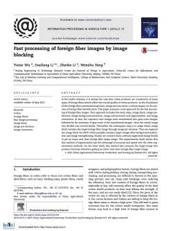
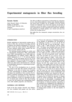
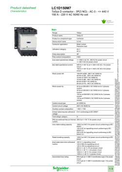
THE ELEMENTS OF
FIBER CABLE MANAGEMENT
BROADBAND NETWORK SOLUTIONS /// THE ELEMENTS OF FIBER CABLE MANAGEMENT
The Elements of Fiber Cable Management
As service providers upgrade their networks to transport high-bandwidth broadband
services, an increase in fiber usage is essential to meet both bandwidth and cost
requirements. But just deploying this additional fiber is not enough – a successful, wellbuilt network must also be based on a strong fiber cable management system.
Proper fiber management has a direct impact on the network’s performance, stability, reliability and cost. Additionally, it affects
network maintenance, operations, expansion, restoration, and the rapid implementation of new services, ideally without disturbing
the transmission in other active circuits. The four primary elements of a strong fiber cable management system provides:
• Storage and protection of fibers, splices, connections, passive optical components, cables
• Fiber and cable routing paths with bend radius control
• Modular circuit separation (to reduce transient losses in adjacent groups of optical circuits)
• Fiber and cable identification and accessibility
Executing these concepts correctly will enable the network to realize its full competitive potential.
With strong demand steadily increasing
for broadband services including
several bandwidth-hungry technologies
such as high-definition television
(HDTV) and higher Internet speeds
for larger file sharing requirements,
fiber is pushing closer and closer
to the customer premises.
This, in turn, creates a need for
additional fiber in the central office
(CO) /data center and for active
equipment that must be managed to
accommodate future network growth.
Any new broadband network
infrastructure must have the inherent
capability to easily migrate to the
next generation of technologies and
services. This is a key consideration for
any provider of triple-play broadband
services – whether it’s from the multiple
service operator (MSO) headend, a
CO, or a wireless mobile switching
center (MSC). As the amount of fiber
dramatically increases, the importance
of properly managing fiber cables
becomes a more crucial issue.
The manner in which fiber cables
are connected, terminated, routed,
spliced, stored, and handled will
directly and substantially impact the
network’s performance, stability and,
more importantly, its profitability.
The four fundamental elements of
fiber cable management – physical
and environmental protection, circuit
separation, cable routing paths with
bend radius control, accessibility and
identification – will be discussed in
Without proper physical protection,
fibers are susceptible to uncontrolled
bends which cause transient
this paper, as well as new technologies
and products developed in the last
few years to improve these elements.
optical losses and damage that
can critically affect network
performance and reliability.
Storage and protection
Fiber and cable
routing paths with
bend radius control
A fiber management system provides
storage and protection (both physical
and environmental) of the installed
fibers, splices, connectors and passive
optical components. Every fiber
throughout the network must be
protected against accidental damage by
technicians or by equipment handling.
Fibers traversing from one piece of
equipment to another must be routed
with physical protection in mind,
such as using raceway systems that
protect from outside disturbances.
Uncontrolled bends in fibers or cables
can affect the fiber network’s longterm reliability and performance.
Uncontrolled bending of fibers is often
caused during handling of the fibers. As
the bend occurs, the radius can become
too small and allow light to escape the
core and enter the cladding. The result
is an increase of attenuation at best
and, at worst, the signal is decreased
Spectral macrobending loss of G652D fiber for 10 loops
4
3.6
MFD (1310 nm): 8.9µm …9.5µm
3.2
Loss (in dB)
Introduction
2.8
R
2.4
Radius 10mm
2
1.6
Radii ≥20mm
1.2
0.8
Radius 15mm
0.4
0
1250
1300
1350 1400 1450 1500
1550 1600 1650
Wavelength (in nm)
Figure 1: Wavelength dependence of macrobending loss
BROADBAND NETWORK SOLUTIONS /// THE ELEMENTS OF FIBER CABLE MANAGEMENT
The Elements of Fiber Cable Management
or completely lost due to a mechanical
fiber fracture. These macrobends can,
however, be reduced and even prevented
through proper fiber handling and
routing in a fiber management system.
The attenuation caused by
macrobending is wavelength dependent
(see Figure 1). For the same bend, the
increase in attenuation will be higher for
the longer wavelengths. As specified in
the standards IEC 61756-1 [1] and ITU-T
L.13 [2] the recommended minimum
permanent storage radius for the
conventional single-mode fibers (ITU-T
G652D) is 30 mm, however, in local
cases a radius of 20 mm is allowed (for
example a bend at a connector boot).
The minimum bend radius of a cabled
fiber will vary depending on the cable
construction. In general, the minimum
bend radius of a cable should not be
less than ten times its outer diameter.
Thus, a 5-mm cable should not have
any bends less than 50 mm in radius.
Also, if a tensile load is applied to a
fiber cable, such as the weight of a
cable in a long vertical run or a cable
pulled tightly between two points,
the minimum bend radius is increased
due to the added stress on the fiber.
The advent of bend insensitive fiber
according to ITU-T G.657 [3] is an example
of how technology has addressed
the bend radius issue and associated
attenuation. Whereas the minimum
bend radius should not be less than ten
times the outer diameter of the fiber
cable in typical fiber, bend insensitive
fiber provides more leeway. A bend
insensitive fiber can be bent with a
30-percent smaller radius compared
to the conventional single-mode fiber
without additional attenuation penalty.
This allows the reduction of the size of
fiber management systems for FTTH
applications where a recommended
minimum bend radius of 20 mm is
used and in some limited cases a 15
mm radius is allowed (for example in
wall outlets). Some bend insensitive
fibers (ITU-T G.657B3) are specified
with a bend radius of 5 mm, which
makes these fibers ideal for customer
premises cabling. However, care
must be taken; for such small bends
the mechanical failure probability
Expected mechanical reliability of fiber lines in various network locations
Wall outlet
Terminal
Core
Long Haul
Trunk
Junction
Metropolitan
Drop
Access network
Splitter
cabinet
Distribution network
Building
distribution box
Very high reliability
Failure probability targets per fiber line
< 10-7 over 20 years for core networks
Impact of a failure is severe (>1000
customers affected)
High reliability
Acceptable reliability
Failure probability targets per fiber line
< 10-6 over 20 years for access networks.
Impact of a failure is relative severe
(less than 64 customers affected)
Failure probability < 10-5 over 20 years
- frequent re-entries expected
- smaller fiber bend radii for smaller products
- cost effective
- impact of a failure is less severe
Figure 2: Expected mechanical reliability in various optical networks
will increase dramatically. For FTTH
customer premises cabling, a mechanical
failure probability of 10-5 is considered
acceptable, but for long haul networks
a failure probability of minimum 10-7
is required since one failure could
affect the transmission of several
thousand customers (see Figure 2).
However, service providers must
understand that these new ITU-T
G.657 fibers do not diminish the need
for solid fiber cable management. On
the contrary, the increase in the sheer
number of fibers being added to the
system to accommodate broadband
upgrades makes bend radius control
as important as ever. Additionally,
the future NG-PON2 systems will use
transmission wavelengths up to 1625 nm,
which makes the fibers very sensitive to
macrobending at these wavelengths.
As fibers are added on top of installed
fibers, macrobends can be induced
on the installed fibers if they are
routed over an unprotected bend. A
fiber that had been working fine for
many years can suddenly have an
increased level of attenuation, as well
as a potentially shorter service life.
Although bend insensitive fiber is an
innovative breakthrough addressing
the issue of bend radius protection,
it may be some time before service
providers replace existing fibers with
a bend insensitive variety of fiber.
Meanwhile, the importance of bend
radius protection is critical to avoid
operational problems in the network.
Improper routing of fibers and cables by
technicians is one of the major causes
of bend radius violations. Wherever
fiber is used, routing paths must be
clearly defined and easy to follow
– to the point where the technician
has no other option than to route
the cables properly. Leaving cable
routing to the technician’s imagination
leads to an inconsistently routed,
difficult-to-manage fiber network.
The quality of the cable routing paths,
particularly within a fiber distribution
frame system, can be the difference
between congested chaos and neatlyplaced, easily accessible, patch cords.
It’s often said that the best teacher
in fiber routing techniques is the
first technician to route it properly.
Conversely, the worst teacher is the
first to use improper techniques since
subsequent technicians are likely to
follow his lead. Well-defined routing
paths, therefore, reduce the proficiency
training time required for technicians
and increase the uniformity of the work
done by ensuring and maintaining
bend radius requirements at all points
to improve overall network reliability.
It is important to note that, again,
the use of bend insensitive fiber does
not diminish the need for clear cable
routing paths – there are benefits that
go beyond bend radius protection.
Defined routing paths make accessing
PAGE 3
The Elements of Fiber Cable Management
Change in attenuation when handling an active fibre
0.5
0.0
-0.5
Short duration
-1.0
Fast transition
-1.5
Fiber identification
and cable access
High attenuation
-2.0
-2.5
-3.0
-3.5
0
0.5
1
Time ( seconds )
1.5
2
Figure 3: Transient optical loss
individual fibers easier, quicker and
safer – reducing the time required
for reconfigurations. Fiber twists are
seconds. The transient loss should
be reduced to a level below 0.5 dB
to avoid transmission errors (or bit
reduced so tracing a particular fiber
for rerouting is much easier. Even
with new technologies, such as the
use of connection point identification
(CPID) at both ends of patch cords for
easy identification, well-defined cable
routing paths still greatly reduce the
time required to route and reroute
patch cords. All of this directly affects
network operating costs and the time
required to turn up or restore service.
errors) in an active optical circuit.
Modular circuit
separation system
The easiest way to increase fiber
capacity is to add as many fibers and
cables as possible in the equipment. This
results in splice trays with more than 96
splices per tray. The drawback of such
mass storage systems is that during an
intervention by a maintenance crew,
many fibers or cables will be touched,
either intentionally or by accident.
The probability of an uncontrolled
fiber bend becomes high, resulting
in rapid changes in attenuation,
also called “transient losses”.
Figure 3 shows a typical transient loss
recorded when an installer handles
fibers. The effects of transient optical
losses on the transmission quality
has been described in many papers
[4] [5]
, . Transient optical losses are fast
changes in attenuation up to 10 dB
with a duration from 1 ms to several
are typically used. In the distribution
points of an access network, where
frequent reentry is expected over
the lifetime of the product, the SC
and SE splice trays are employed.
In network locations that require
frequent interventions, such as the
access network, it makes sense to
separate the optical fiber circuits by
storing the fibers on individual splice
trays. This reduces the occurrence of
transient optical losses in adjacent
circuits. Circuit separation is defined and
described by the international standards
IEC 61756-1 [1] and ITU-T L51 [6]. The
following separation levels are defined:
•
Single circuit (SC): only the fibers
of one customer per splice tray
•
Single ribbon (SR): only one
ribbon per splice tray
•
Single element (SE): all fibers
from a cable element (e.g. a
loose tube) per splice tray
•
Multi-element (ME): fibers
from multiple cable elements
on one splice tray (also called
mass storage trays)
A fiber management system should
allow modular combination of splice
trays with the above mentioned circuit
separation levels. Depending on the
application, the type of splice tray
can be changed. For example, in a
long distance network where cable
segments are spliced together (in track
joints) and where closure reentry is not
expected, the SE and ME splice trays
BROADBAND NETWORK SOLUTIONS /// THE ELEMENTS OF FIBER CABLE MANAGEMENT
Cable access and identification is
another important element to good fiber
cable management and refers to the
accessibility of the installed fibers. As
the number of fibers grows dramatically
in both the distribution frame and the
active equipment, cable access becomes
an increasingly important issue for
broadband service providers. In the
past, an active equipment rack might
have had about 50 fibers exiting, and
managing those fibers was much less of
an issue. But as that same rack is fitted
for next generation broadband services,
there may be as many as 500 fibers
involved, making proper management,
identification and accessibility a
vitally important matter. Using SC and
SE circuit separation levels will help
identify the correct fiber circuits.
With huge amounts of data – as well as
revenue – moving across those fibers,
the ability for technicians to have quick,
correct and easy access is critical. When
there are service level agreements
in place, particularly for customers
with high priority traffic, the last thing
any service provider wants is service
interruptions caused by mishandling
one fiber to gain access to another.
As previously mentioned, there are
patch cords designed today with
connection point identification (CPID)
at both ends to help technicians
identify particular cable runs with no
chance of error. These innovations can
be implemented into a good cable
management system to minimize
problems caused by disconnecting
the wrong patch cord. There are
many other tools and techniques
for ensuring that every fiber can be
installed or removed without bending
or disturbing an adjacent fiber.
The accessibility of the fibers in the
fiber cable management system
can mean the difference between a
The Elements of Fiber Cable Management
network reconfiguration time of 20
minutes per fiber and one of over 90
minutes per fiber. Since accessibility
is most critical during network
reconfiguration operations, proper cable
access directly impacts operational
costs and network reliability.
A final word – planning
Finally, since many service providers
are in the process – or soon will be –
of upgrading networks for delivery of
high-bandwidth broadband services,
it is important to stress the need for
planning in terms of fiber and cable
management. Today’s network is a living
and growing entity – and what is enough
today will almost certainly be too little
for tomorrow. With that in mind, futureproofing the network wherever possible
should be a major consideration – and
fiber cable management is no different.
For example, the current upgrades
to broadband service delivery taking
place in COs, MSOs, or MSCs requires
more fiber deployment. Four- and
six-inch (102mm and 132mm) fiber
raceway systems are quickly becoming
inadequate to properly manage larger
amounts of fiber. Service providers
must plan ahead for a centralized, highdensity fiber distribution frame lineup
using 24-inch (610mm) raceways that
not only accommodate today’s fiber
requirements, but also those expected
in the future. Although installing a 24inch raceway system is more expensive
today, the cost of going back in and
retrofitting the system in a few years
represents a much higher cost and
significant risk to the fiber. Ignoring
future growth, particularly in terms of
fiber, will result in higher long-term
operational costs resulting from poor
network performance or a requirement
to retrofit products that can no longer
accommodate network demand.
Another consideration in planning
for good fiber cable management
concerns the active equipment rack.
Most manufacturers have traditionally
overlooked the need to provide
cable management within their
active equipment. Before purchasing,
service providers should insist that
cable management is included within
every piece of active equipment to
ensure their investment will operate
at peak efficiently over time.
References
[1] IEC 61756-1 Fiber optic interconnecting devices and passive components - Interface standard for fiber management systems - Part 1: General and guidance
[2] ITU-T L.13 Performance requirements for passive optical nodes: Sealed closures for outdoor environments
[3] ITU-T G.657 Transmission media and optical systems characteristics –Optical fiber cables. Characteristics of a bending-loss insensitive single-mode optical fiber and
cable for the access network
[4] D. Daems, “Effects of Transient Optical Loss in STM-64 Transmission Systems,” NFOEC Proceedings, Vol. 1, 290 (2002).
[5] John W. Peters and Osman S. Gebizlioglu, “FDF operations testing: transient optical loss and BER (Bit Error Ratio) measurements. NFOEC Proceedings, Vol. 4, 1218
(2003).
[6] ITU-T L.51 Passive node elements for fiber optic networks – General principles and definitions for characterization and performance evaluation
DANIEL DAEMS
Daniel Daems received his M.S. degree in Electromechanical Engineering at the
Polytechnic Institute of the Free University of Brussels (VUB), Belgium in 1982.
He joined the company Raychem in 1988 and was involved in the development of optical fiber management
systems and closures suited for outside plant applications. He is currently Senior R&D Department
Manager of the Fiber Optic Technology and Standards Department at TE Connectivity in Belgium.
He is Chairman of IEC SC86B (Fiber optic interconnecting devices and passive components) and
Convenor of the Cenelec (European standards) TC86BXA WG2 for fiber optic enclosures.
PAGE 5
te.com
TE Connectivity, TE connectivity (logo) and Every Connection Counts are trademarks. All other logos, products
and/or company names referred to herein might be trademarks of their respective owners.
The information given herein, including drawings, illustrations and schematics which are intended for illustration
purposes only, is believed to be reliable. However, TE Connectivity makes no warranties as to its accuracy or
completeness and disclaims any liability in connection with its use. TE Connectivity‘s obligations shall only be
as set forth in TE Connectivity‘s Standard Terms and Conditions of Sale for this product and in no case will TE
Connectivity be liable for any incidental, indirect or consequential damages arising out of the sale, resale, use
or misuse of the product. Users of TE Connectivity products should make their own evaluation to determine the
suitability of each such product for the specific application.
© 2014 TE Connectivity Ltd. family of companies All Rights Reserved.
319842 01/15 Original
BROADBAND NETWORK SOLUTIONS /// THE ELEMENTS OF FIBER CABLE MANAGEMENT
WHITE PAPER
TE Connectivity
Broadband Network Solutions - EMEA
Diestsesteenweg 692
3010 Kessel-Lo, Belgium
Tel 32-16 351 011
www.te.com/bns
Tyco Electronics Raychem bvba,
a TE connectivity company.


© Copyright 2026