
Dokument_1 - OPUS - Universität Augsburg
Universität
Augsburg
Institut für
Mathematik
St´ephane Bordas, Ronald H.W. Hoppe, Svetozara I. Petrova
Mechanical Failure in Microstructural Heterogeneous Materials
Preprint Nr. 003/2007 — 22. Mai 2007
Institut f¨
ur Mathematik, Universit¨atsstraße, D-86 135 Augsburg
http://www.math.uni-augsburg.de/
Impressum:
Herausgeber:
Institut f¨ur Mathematik
Universit¨at Augsburg
86135 Augsburg
http://www.math.uni-augsburg.de/forschung/preprint/
ViSdP:
Ronald H.W. Hoppe
Institut f¨ur Mathematik
Universit¨at Augsburg
86135 Augsburg
Preprint: S¨amtliche Rechte verbleiben den Autoren c 2007
Mechanical Failure in Microstructural
Heterogeneous Materials
St´ephane Bordas1, Ronald H.W. Hoppe2,3 , and Svetozara I. Petrova2,4
1
Laboratory of structural and continuum mechanics, EPFL, Lausanne, Switzerland
2
Institute of Mathematics, University of Augsburg, 86159 Augsburg, Germany
3
Department of Mathematics, University of Houston, TX 77204–3008, USA
4
Institute for Parallel Processing, BAS, Block 25A, 1113 Sofia, Bulgaria
Abstract. Various heterogeneous materials with multiple scales and
multiple phases in the microstructure have been produced in the recent
years. We consider a mechanical failure due to the initiation and propagation of cracks in places of high pore density in the microstructures.
A multi–scale method based on the asymptotic homogenization theory
together with the mesh superposition method (s-version of FEM) is presented for modeling of cracks. The homogenization approach is used on
the global domain excluding the vicinity of the crack where the periodicity of the microstructures is lost and this approach fails. The multiple
scale method relies on efficient combination of both macroscopic and microscopic models. The mesh superposition method uses two independent
(global and local) finite element meshes and the concept of superposing the local mesh onto the global continuous mesh in such a way that
both meshes not necessarily coincide. The homogenized material model
is considered on the global mesh while the crack is analyzed in the local domain (patch) which allows to have an arbitrary geometry with
respect to the underlying global finite elements. Numerical experiments
for biomorphic cellular ceramics with porous microstructures produced
from natural wood are presented.
1
Global–Local Approach for Heterogeneous Materials
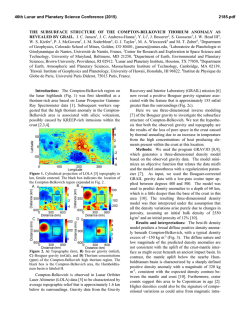
Consider a domain Ω ⊂ Rd , d = 2, 3, occupied by a heterogeneous material
with microstructures of periodically distributed constituents. Suppose that the
boundary of Ω, denoted by Γ , consists of a prescribed displacement boundary
ΓD (meas ΓD > 0) and a prescribed traction boundary ΓT , such that Γ =
ΓD ∪ ΓT , ΓD ∩ ΓT = ∅, as shown in Figure 1.
Assume that the periodic cells in the macrostructure are infinitely many but
infinitely small and repeated periodically through the medium. The unit microstructure consists of different material constituents and a pore. Both the
This work has been partially supported by the German National Science Foundation
(DFG) under Grant No.HO877/5-3. The third author has also been supported in part
by the Bulgarian Ministry for Education and Science under Grant I1402/2004.
T. Boyanov et al. (Eds.): NMA 2006, LNCS 4310, pp. 533–541, 2007.
c Springer-Verlag Berlin Heidelberg 2007
534
S. Bordas, R.H.W. Hoppe, and S.I. Petrova
Periodic structure
111111111111111111
000000000000000000
000000000000000000
111111111111111111
000000000000000000
111111111111111111
000000000000000000
111111111111111111
T
000000000000000000
111111111111111111
000000000000000000
111111111111111111
000000000000000000
111111111111111111
000000000000000000
111111111111111111
000000000000000000
111111111111111111
000000000000000000
111111111111111111
000000000000000000
111111111111111111
000000000000000000
111111111111111111
000000000000000000
111111111111111111
000000000000000000
111111111111111111
000000000000000000
111111111111111111
000000000000000000
111111111111111111
000000000000000000
111111111111111111
000000000000000000
111111111111111111
000000000000000000
111111111111111111
000000000000000000
111111111111111111
000000000000000000
111111111111111111
000000000000000000
111111111111111111
000000000000000000
111111111111111111
C
000000000
111111111
000000000000000000
111111111111111111
000000000
111111111
000000000000000000
111111111111111111
000000000
111111111
000000000000000000
111111111111111111
000000000
111111111
000000000000000000
111111111111111111
000000000000000000
111111111111111111
000000000000000000
111111111111111111
000000000000000000
111111111111111111
000000000000000000
111111111111111111
000000000000000000
111111111111111111
000000000000000000
111111111111111111
000000000000000000
111111111111111111
000000000000000000
111111111111111111
000000000000000000
111111111111111111
000000000000000000
111111111111111111
000000000000000000
111111111111111111
Γ
Unit microstructure
Ω
Γ
11111
00000
00000
11111
00000
11111
00000
11111
00000
11111
00000
11111
00000
11111
11111
00000
11111
00000
crack
ΓD
Homogenized cell
Homogenized material model
Fig. 1. Crack in the macroscopic homogenized material model
macroscopic and microscopic scales are well separated, i.e., the size of the microstructure in the heterogeneous material is much smaller than those of the
macroscopic component. The asymptotic homogenization theory [1,2] is applied
to find the effective (homogenized) properties of the material and to derive the
homogenized macroscopic model. Details are given in the next Section. The
main idea for the homogenization of a heterogeneous material with a periodical
distribution of microstructures is illustrated in Figure 1.
We allow the domain Ω to contain discontinuities and consider the crack
problem with a crack ΓC , see Figure 1. The crack is a multiscale effect which
typically appears in regions with microstructures of increasing porosity. The
periodicity fails for those microstructures cut by the crack. Therefore, a new
finite element analysis has to incorporate microstructural information about the
nucleation and growth of micropores. We rely on the mesh superposition method
(known as s-version of FEM), first developed in [7,8]. The method is based on a
finite element approximation by using two independent meshes: the global mesh
for the whole domain (also called in the literature a background mesh) and a
local mesh in the critical region near the crack (also called a patch mesh). The
local mesh is arbitrarily superimposed onto the global mesh without taking care
of the matching between nodes in both meshes.
Consider the following governing equations in the domain Ω
−∇·σ = b
u=g
σ·n=t
in Ω
on ΓD
(1)
(2)
on ΓT ,
(3)
where σ is the second order symmetric stress tensor, b is the body force, g is the
prescribed displacement on ΓD , t is the prescribed traction on ΓT , and n is the
unit normal to the boundary ΓT . A traction–free surface σ · n = 0 is assumed
on the crack ΓC . In case of small strains and displacements, the second order
strain tensor e is given by
Mechanical Failure in Microstructural Heterogeneous Materials
e = e(u) = ∇u + (∇u)T /2,
535
(4)
where ∇u is the gradient operator. If a linear elasticity is assumed, the constitutive relation is presented by the linearized Hooke law σ = E: e, where E is
the fourth–order elasticity tensor which depends on the material constants like
Young’s modulus and Poisson’s ratio.
The weak form of the governing equation (1) reads: Find u ∈ U , such that
e(v): σ(u) dΩ =
Ω
b · v dΩ +
Ω
t · v dΓ,
∀ v ∈ U0 ,
(5)
ΓT
where the set of admissible displacement fields is defined by
U = {v | v ∈ V, v = g on ΓD , v discontinuous on ΓC }
(6)
and the test function space is defined by
U0 = {v | v ∈ V, v = 0 on ΓD , v discontinuous on ΓC }.
(7)
The space V is related to the regularity of the solution in Ω and allows for
discontinuous functions across the crack. At each point x ∈ Ω we consider a
finite element discretization of (5) with a basis taken from the test function
space U0 and nodal shape functions N (x) constructed by the Galerkin method.
We denote the local critical region onto which the local mesh is superimposed
by Ω L , Ω L ⊂ Ω, a subset of Ω, containing the crack. Let Ω G = Ω \ Ω L be
the rest of the domain excluding discontinuities. The domains Ω and Ω L are
discretized independently by separate sets of finite elements ΩeG and ΩeL , such
that ΩeG = Ω and ΩeL = Ω L . Here, the superscript G relates to the global
(underlying) mesh and L to the local (superimposed) mesh. Γ GL is the boundary
between the two meshes excluding external boundaries, i.e., Γ ∩ Γ GL = ∅.
Let uG be the global displacement field defined in Ω and uL be the local displacement field defined in the local region Ω L . Note that the superimposed field
uL is in general discontinuous due to a discontinuity across the crack faces. The
total displacement field u is constructed by superposition of both displacement
fields on the separate meshes and can be written as follows
u=
uG
on Ω G , Γ GL
uG + uL on Ω L .
(8)
To insure displacement compatibility between the global and local meshes, we
assume homogeneous boundary conditions on the boundary of the patch, i.e.,
uL = 0 on Γ GL . Denote by B G and B L the discretized gradient operators (also
called strain–displacement matrices) for the global and local meshes, respectively.
Then, the strain can be expressed as follows
e=
eG = B G u G
on Ω G
eL = B G uG + B L uL on Ω L .
(9)
536
S. Bordas, R.H.W. Hoppe, and S.I. Petrova
Based on the Hooke law we get the following constitutive relations
σ = E: e =
σ G = E G : (B G uG )
on Ω G
σ L = E L : (B G uG + B L uL ) on Ω L ,
(10)
where E G and E L are the elasticity tensors corresponding to the different constitutive laws. By using shape functions N G (x) on the global mesh and shape
functions N L (x) on the local mesh, one can get from the standard weak form
(5) the following two equations
ΩG
B G (x): σ G (u) dΩ =
B L (x): σ L (u) dΩ =
ΩL
ΩG
ΩL
N G (x) · b dΩ +
N L (x) · b dΩ +
ΓTG
ΓTL
N G (x) · t dΓ,
(11)
N L (x) · t dΓ,
(12)
where ΓTG = ΓT ∩ Ω G and ΓTL = ΓT ∩ Ω L . Substituting (8)–(10) in equations
(11)–(12), we obtain the following discrete system
KG
K GL
GL T
(K ) K L
uG
uL
=
fG
fL
,
(13)
where K G and K L are the stiffness matrices corresponding to the global and local meshes, respectively, and K GL is the matrix corresponding to the interaction
between the two meshes, namely
KG =
ΩG
K GL =
ΩL
(B G (x))T E G B G (x) dΩ +
ΩL
(B G (x))T E L B L (x) dΩ, K L =
(B G (x))T E L B G (x) dΩ,
ΩL
(14)
(B L (x))T E L B L (x) dΩ. (15)
The force vectors f G and f L are computed from the right–hand sides of (11)
and (12), respectively. Note that N G (x) are the shape functions corresponding
to finite elements in the global mesh on which continuous displacement field uG
is considered. Furthermore, N L (x) are the discontinuous shape functions of the
elements chosen on the local domain to model the crack. The elements of the
global and local meshes should not coincide. The cracked mesh is superimposed
on the continuous mesh in Ω L by using the s-method. The main difficulty of
this method is the numerical integration based on Gauss quadratures when solving the system (13). An attractive approach is recently proposed in [10] where
only the near–tip crack fields are modeled on a superimposed patch (overlaid
mesh) and the rest of the crack is treated within the framework of the eXtended
Finite Element Method (Xfem ) by introducing additional discontinuous enrichment functions for the elements completely cut by the crack, see [11]. The
latter method is also used in our numerical experiments and briefly explained in
Section 3.
Mechanical Failure in Microstructural Heterogeneous Materials
2
537
Multi–Scale Method
In this section, we describe the multi–scale method based on the asymptotic
homogenization theory together with the mesh superposition method. For more
details we refer the reader to [16]. The homogenization approach is used on
the global domain excluding the vicinity of the crack where the periodicity of
the microstructures is lost and this approach is not applicable. The crack is
considered in the local domain (patch). Two independent (global and local)
meshes are generated in the global and local domains, respectively. The patch
is allowed to have an arbitrary geometry with respect to the underlying global
finite elements. The total displacement field (8) is approximated by adding global
(underlying) and local (superimposed) fields and hence, it is discontinuous across
the crack.
A double–scale asymptotic expansion for the displacement field and a homogenization procedure by taking a zero limit of the scale ratio are applied
to come up with computationally feasible macromodels [1,2]. The homogenized
macroscopic problem is involved in the governing equation (1). Furthermore, introducing global and local meshes, the global displacement field uG is expressed
by the homogenized displacement, the leading term in the asymptotic expansion form (see, e.g., [9]). The homogenized elasticity problem is transformed to
solving the system (13) with a symmetric and usually, sparse, stiffness matrix
coupling the integrands on the global and local meshes. Note that the elasticity
tensor E G in the expression (14) is replaced now by the homogenized elasticity
tensor E H with components computed as follows
H
=
Eijkl
1
|Y |
Eijkl (y) − Eijpq (y)
Y
∂ξpkl
∂yq
dY,
(16)
where Eijkl are the elasticity coefficients corresponding to the different material layers in the microstructure. The periodic functions ξ kl (also referred to
as characteristic displacements) satisfy the following elasticity equation in the
microscopic unit cell
Eijpq (y)
Y
∂ξpkl ∂φi
dY =
∂yq ∂yj
Eijkl (y)
Y
∂φi
dY,
∂yj
(17)
where φ ∈ H 1 (Y ) is an arbitrary Y −periodic variational function. The multi–
scale procedure is realized by the following Multi–Scale Algorithm (MSA)
Step
Step
Step
Step
Step
Step
Step
1.
2.
3.
4.
5.
6.
7.
Select a unit microstructure Y in the heterogeneous material.
Solve (17) to find the characteristic displacement fields ξ kl .
Compute the homogenized coefficients (16) and set E G = E H .
Generate a global mesh in Ω on the macroscopic homogenized model.
Introduce a local (discontinuous) mesh near the crack ΓC .
Solve (13) to determine the displacements uG and uL .
Substitute uG and uL in (9) and (10) to find the strains and stresses.
538
3
S. Bordas, R.H.W. Hoppe, and S.I. Petrova
Crack Modeling with Partition of Unity Enrichment
The extended finite element method [3,11,15] allows treating crack problems
without meshing the discontinuity surface. This is possible through enrichment
of the standard polynomial finite element space with special functions: discontinuous, to account for the displacement jump, and crack–tip fields to reduce
the mesh density required for accurate fracture parameter computations. The
method is now becoming quite mature, and has already been applied to industrial fracture mechanics problems [5].
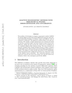
Some elements are split by the crack and others contain the crack tips. Nodes
whose support is cut by a crack are in set Ncr , while nodes whose support
contains one tip are in the set Ntip , as in Figure 2.
Fig. 2. Selection of enriched nodes. Circled nodes (set of nodes Ncr ) are enriched with
the step function whereas the squared nodes (set of nodes Ntip ) are enriched with the
crack tip functions: a) on structured mesh; b) on unstructured mesh.
The Xfem approximation reads
uh (x) =
NJ (x)(H(x) − H(xJ ))aJ
NI (x)uI +
I∈N
J∈Ncr
4
(Bα (x) − Bα (xK ))bαK ,
NK (x)
+
K∈Ntip
(18)
α=1
where NI (x) and NJ (x) are finite element shape functions, while uI , aJ and bαK
are the displacement and enrichment nodal variables, respectively. Note that the
shape functions NJ (x) associated with the enrichment can differ from the shape
functions NI (x) used for the standard part of the displacement approximation.
H(x) is the modified Heaviside function which takes on the value +1 above
the crack and -1 below the crack and Bα (x) is a basis that spans the near tip
asymptotic field:
B ≡ [B1 , B2 , B3 , B4 ] =
√
√
θ √
θ √
θ
θ
r sin , r cos , r sin cos θ, r cos cos θ
2
2
2
2
(19)
From the enriched approximation (18), Bubnov–Galerkin procedure gives discrete equations of the form Kd = f . Numerical integration for split elements is
done here by partitioning the elements into sub–triangles. Interested readers can
refer to [4,13] for details.
Mechanical Failure in Microstructural Heterogeneous Materials
4
539
Numerical Experiments
The fracture mechanics computations in this section are performed using the
Xfem library OpenXfem++ [6]1 . Our numerical examples concern biomorphic
silicon carbide (SiC) cellular ceramics with porous microstructures produced
from natural wood. The open porous system of tracheidal cells which provide
the transportation path for water and minerals in the living plants is accessible
for infiltration of various liquid or gaseous metals (see, e.g., [14] for the production process). Numerical experiments for the homogenized coefficients in a 2-D
material workpiece are given in [9].
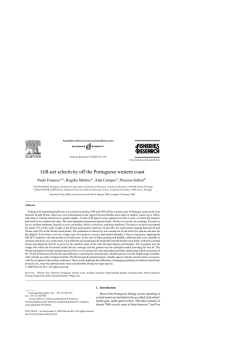
Consider a stationary microstructure with a geometrically simple tracheidal
periodicity cell Y = [0, 1]2 consisting of an outer layer of carbon (C), interior
layer of silicon carbide (SiC), and a centered pore channel (P, no material), see
Figure 3a). One can also deal with the so–called pure SiC ceramics when enough
silicon is infiltrated in the pore channel until the complete reaction between the
carbon and silicon, see Figure 3b). The Young modulus E (in GPa) and the
Poisson ratio ν of our two materials are, respectively, E = 10, ν = 0.22 for
carbon and E = 410, ν = 0.14 for SiC.
Pore
Pore
SiC
Carbon
SiC
Fig. 3. a) Unit cell Y = P ∪ SiC ∪ C; b) Pure SiC ceramics: Y = P ∪ SiC
As a first attempt we consider a crack in the macroscopic homogenized model.
All computations are performed assuming the theory of Linear Elastic Fracture
Mechanics. In Table 1 we report the evaluated data for the homogenized Young
modulus E H (in GPa) and the homogenized Poisson ratio ν H . In case of SiC
ceramics the coefficients are computed for equal widths of the SiC and carbon
layers, see Table 1a). The density of the SiC layer and the density of the carbon
layer are denoted, respectively, by μSiC and μcarbon . Note that the porosity is
determined by: meas(Y ) − μSiC − μcarbon . In case of pure SiC ceramics, see
Table 1b), the porosity is given by: meas(Y ) − μSiC .
2
) with E =
In all problems, the energy release rate G = E1 (KI2 + KII
H
H 2
E / 1 − (ν ) is computed for both crack tips. The stress intensity factors
(SIFs), KI and KII , for mode I and II, respectively, are determined using the
domain form of the interaction integrals [12]. We are interested in the effect of
porosity on the energy release rate. Consider a center crack in an infinite plate
under remote, unit, uniaxial tension. The geometry of the plate is (2x6), the
1
Available on request.
540
S. Bordas, R.H.W. Hoppe, and S.I. Petrova
Table 1. Homogenized E and ν: a) SiC ceramics; b) Pure SiC ceramics
porosity μSiC
0.81
0.64
0.36
0.25
0.16
0.09
0.04
0.01
0.0925
0.17
0.28
0.3125
0.33
0.3325
0.32
0.2925
μcarbon E H (GPa) ν H
porosity μSiC
0.0925
0.19
0.36
0.4375
0.51
0.5775
0.64
0.6975
0.9025
0.7225
0.5625
0.4225
0.3025
0.2025
0.1225
0.0025
89.42
66.52
43.47
37.29
31.31
25.99
21.69
18.56
0.035
0.069
0.142
0.145
0.137
0.140
0.153
0.168
0.0975
0.2775
0.4375
0.5775
0.6975
0.7975
0.8775
0.9975
E H (GPa) ν H
216.10
231.94
248.93
267.94
289.27
314.16
342.27
409.14
0.016
0.040
0.062
0.083
0.104
0.124
0.138
0.139
crack length is 0.25, and the mesh, completely regular and non–conforming to
the crack, contains 2701 four–noded quadrilateral elements. The radius of the
circular interaction integral domain is twice the size of the element containing
the tip. Note that in this case, the exact SIFs are actually known analytically.
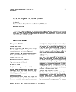
The computed SIFs are within one percent of the exact values. The evolution
of the energy release rate G as a function of porosity is given in Figure 4b)
and shows that, as expected, the energy release rate increases with increasing
porosity, i.e. as the pure SiC ceramics become more rigid.
1.935
−3
x 10 RELATION BETWEEN POROSITY VERSUS THE ENERGY RELEASE RATE
2.9
−4
x 10 RELATION BETWEEN POROSITY VERSUS THE ENERGY RELEASE RATE
Tip 1
Tip 2
Tip 1
Tip 2
2.895
Energy release rate G
Energy release rate G
1.93
1.925
1.92
1.915
2.89
2.885
2.88
2.875
1.91
1.905
2.87
0
0.1
0.2
0.3
0.4
0.5
Porosity Factors
0.6
0.7
0.8
0.9
2.865
0
0.2
0.4
0.6
Porosity Factors
0.8
1
Fig. 4. Porosity versus the energy release rate G: a) SiC ceramics; b) Pure SiC ceramics
The same problem was solved for a layered SiC ceramics, and results are
reported in Figure 4a). We note that the behavior is somewhat more complex
in this case, where we observe a decreasing energy release rate for porosities
comprised between 0.15 and 0.25.
References
1. Bensoussan, A., Lions, J.L., Papanicolaou, G.: Asymptotic Analysis for Periodic
Structures. North–Holland, Elsevier Science Publishers, Amsterdam, (1978).
2. Jikov, V.V., Kozlov, S.M., Oleinik, O.A.: Homogenization of Differential Operators
and Integral Functionals. Springer, (1994).
Mechanical Failure in Microstructural Heterogeneous Materials
541
3. Belytschko T., Mo¨es N., Usui S., Parimi C.: Arbitrary discontinuities in finite
elements. Int. J. Numer. Methods Eng., 50 (4) (2001) 993–1013.
4. Bordas S., Legay A.: Enriched finite element short course: class notes. Organized
by S. Bordas and A. Legay through the EPFL school of continuing education,
Lausanne, Switzerland, December 7–9, 2005.
5. Bordas S., Moran B.: Extended finite element and level set method for damage
tolerance assessment of complex structures. Eng. Fract. Mech., 73 (9) (2006) 1176–
1201.
6. Bordas S., Nguyen V.P., Dunant C., Nguyen-Dang H., Guidoum A.: An object–
oriented extended finite element library. Int. J. Numer. Methods Eng., (2006) (to
appear).
7. Fish J.: The s-version of the finite element method. Comput. Struct., 43 (3) (1992)
539–547.
8. Fish J., Guttal R.: The s-version of finite element method for laminated composites.
Int. J. Numer. Methods Eng., 39 (21) (1996) 3641–3662.
9. Hoppe R.H.W., Petrova S.I.: Optimal shape design in biomimetics based on homogenization and adaptivity. Math. Comput. Simul., 65 (3) (2004) 257–272.
10. Lee S.-H., Song J.-H., Yoon Y.-C., Zi G., Belytschko T.: Combined extended and
superimposed finite element method for cracks. Int. J. Numer. Methods Eng., 59 (8)
(2004) 1119–1136.
11. Mo¨es N., Dolbow J., Belytschko T.: A finite element method for crack growth
without remeshing. Int. J. Numer. Methods Eng., 46 (1) (1999) 131–150.
12. Moran, B., Shih, C.F.: Crack tip and associated domain integrals from momentum
and energy balance. Eng. Fract. Mech., 27 (1987) 615–641.
13. Nguyen V.P.: An object oriented approach to the X-FEM with applications to
fracture mechanics. Master’s thesis, EMMC–Hochiminh University of Technology,
Vietnam, November (2005).
14. Ota T., Takahashi M., Hibi T., Ozawa M., Suzuki S., Hikichi Y., Suzuki H.:
Biomimetic process for producing SiC wood. J. Amer. Ceram. Soc., 78 (1995)
3409–3411.
15. Sukumar N., Pr´evost J.-H.: Modeling quasi–static crack growth with the extended
finite element method. Part I: Computer implementation. Int. J. Solids Struct., 40
(2003) 7513–7537.
16. Takano N., Zako M., Okuno Y.: Multi–scale finite element analysis of porous materials and components by asymptotic homogenization theory and enhanced mesh
superposition method. Modelling Simul. Mater. Sci. Eng., 11 (2003) 137–156.

© Copyright 2026