
Wattstopper
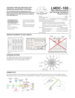
LMSW-105
THIS UNIT IS PRE-SET FOR
PLUG n’ GO OPERATION,
ADJUSTMENT IS OPTIONAL.
Low Voltage Scene Switch
For full operational details, adjustment and more
features of the product, see the DLM System
Installation Guide at www.wattstopper.com
Installation shall be in accordance with all applicable
regulations, and codes.
To be connected to a Class 2 power source only.
Class 2 Device Wiring Only – Do Not Reclassify and Install
as Class 1, or Power and Lighting Wiring.
Wire connections shall be rated suitable for the wire size
(lead and building wiring) employed.
SPECIFICATIONS
Voltage ....................................................24VDC
Current Consumption ................................5mA
Power Supply ..WattStopper Room Controllers
Connection to the DLM Local
Network ...................................... 2 RJ-45 ports
DLM Local Network characteristics when using
LMRC-2xx/3xx room controllers:
Low voltage power provided over Cat 5e cable
(LMRJ); max current 800mA. Supports up to 64
load addresses, 48 communicating devices including up to 4 LMRC-10x
series and/or LMPL-101 controllers. Free topology up to 1,000’ max.
Environment ....................................................... For Indoor Use Only
Operating Temperature ..........................32° to 131°F (0° to 55°C)
Storage Temperature ............................ 23° to 176°F (-5° to 80°C)
Relative Humidity .................................5 to 95% (non condensing)
Patent Pending
BUTTONS AND INDICATORS
MOUNTING THE SWITCH
Tap when load OFF:
Turn ON to last level
Tap when load ON:
Go to full bright
Press & Hold:
Ramp Up
Blue Status LEDs
Scene Button (4)
Configuration Button
(behind switch plate)
Tap when load ON:
Turn OFF
Press & Hold:
Ramp Down
Red LED
When all loads bound to the dimmer paddle are OFF, it’s
Blue status LED is dim. When any load bound to the dimmer
paddle is ON it’s Blue status LED is bright.
WARNING: Do Not Install To Cover a Junction Box
Having Class 1, 3 or Power and Lighting Circuits.
When a scene is active the LED on the scene button is bright.
CONNECTIVITY
The illustrations show examples of free-topology wiring.
The LMSW-105 communicates with all other Digital Lighting
Management devices connected to the low voltage DLM
Local Network.
Corner Mount
Occupancy
Sensor
J Box
LMDM-101
Dimming Switch
LMSW-105
Scene Switch
LMRC-21x
Room
Controller
Daylighting
Sensor
Occupancy Sensor
DLM Local Network
(low voltage, Class 2)
LMRJ cables
LMRJ from
Room
Controller
To
Load
To 0-10V
Dimming Ballast
Line Voltage
Class 2 0-10 Volt Control Wiring
LMDM-101
Dimming Switch
LMRJ Cables
LMRC-212
Dimming
Room
Controller
J-Box
Line Voltage
0-10 Volt
Ballast
0-10 Volt
Ballast
Ceiling Mount
Occupancy
Sensor
Switch/
Dimmer
Quick Start Guide
Digital Lighting Management
PLUG n’ GO OPERATION (PnG)
All loads are bound to all buttons and the dimmer paddle on
the LMSW-105. The scene buttons are set at the factory to
recall scenes 1-4. Dimmable loads dim (ramp up or down)
in response to pressing and holding either the top or bottom
of the paddle. Switched loads turn OFF when ramped down
below 50% and turn ON when ramped up above 50%.
Default light
level
Scene 1
100%
Scene 2
75%
Scene 3
50%
Scene 4
25%
To change the recorded light levels for any scene simply
adjust the lights in the room to the desired levels and then
press and hold the desired scene button for 5 seconds.
Note: If there are lights that you want turned OFF for a
scene, make sure that those lights are OFF when you record
the scene. If there are lights in the room that you want to be
unaffected by the scene, then you must unbind those lights
from the scene button using Push n’ Learn.
User Customization
A user guide is provided with the scene switch. It describes
basic operation and various procedures that can be used to
make operational changes without tools or assistance from
a technician.
Be sure to leave the User Guide with your customer to avoid
unnecessary service call-backs. It is also available from the
WattStopper website.
UNIT ADJUSTMENT - PUSH n’ LEARN (PnL)
Load Selection Procedure
A configuration button allows access to our patented Push
n’ Learn™ technology to change the binding relationship
between control devices and loads.
Step 1: Enter Push n’ Learn
Using a pointed tool, press and hold the configuration
button for 3 seconds, until the Red LED on the switch
begins to blink.
When you release the configuration button, the red LED
on other communicating DLM Local Network devices
begins to blink rapidly.
The DLM Local Network is now in PnL
mode. The Red LEDs continue to blink
until you exit PnL mode.
All loads in the room turn OFF after
entering PnL. After one second, one
load turns ON. This is Load #1, which is
bound to the LMSW-105 paddle and all
scene buttons as part of the Plug n’ Go
factory default setting. The Blue LED will be ON bright
for all switch buttons, dimmers, scene buttons and
sensors that are bound to this load.
TROUBLESHOOTING
Loads do not operate as expected.
Step 2: Load selection
Press and release the configuration button to step
through the loads connected to the DLM Local Network.
As each load turns ON note which devices
(dimmers, scene and switch buttons
and sensors) are showing the blue
LED. These devices are currently
bound to the load that is ON.
To unbind a button from a load,
press the button while its blue LED
is ON. The blue LED turns OFF
to indicate the button no longer
controls the load that is currently ON. On the scene
switch, unbinding a load from a scene button removes
it from the scene so that when the scene activates the
load’s state does not change.
Pressing the switch button again while the load is
ON rebinds the load to the button and the blue LED
illuminates.
Step 3: Exit Push n’ Learn
Press and hold the configuration button until the red
LED turns off, approximately 3 seconds.
WARNING: TO CONNECT A COMPUTER TO THE DLM LOCAL NETWORK USE THE
LMCI-100. NEVER CONNECT THE DLM LOCAL NETWORK TO AN ETHERNET PORT
– DOING SO MAY DAMAGE COMPUTERS AND OTHER CONNECTED EQUIPMENT.
Button LEDs don’t light
1. Check to see that the the switch is connected to the DLM Local Network.
2. Check for 24VDC input to the switch: Plug in a different DLM device at the switch location. If
the device does not power up, 24VDC is not present.
• Check the high voltage connections to the room controller.
• If high voltage connections are good and high voltage is present, recheck DLM Local
Network connections between the switch and the room controller.
The wrong lights are
controlled
1. Configure the scene buttons and dimming paddle to control the desired lights using the
Push n’ Learn adjustment procedure.
Button doesn’t actuate
1. Make sure the switch frame and button are assembled properly.
2. Make sure that the wall plate is not pinching the frame.
LEDs change status but
loads don’t change
1. Make sure device is not in PnL.
2. Check load connections to room controller.
2800 De La Cruz Blvd.
Santa Clara, CA 95050
Phone: 800.879.8585
www.wattstopper.com
7/2010
12230r2
Please
Recycle


© Copyright 2026