
GEX69...C - LOVATO Electric SpA
31100265
GB MOTORISED CONTROL UNIT
G
B
I451 I GB D F E 07 16
LOVATO ELECTRIC S.P.A.
24020 GORLE (BERGAMO) ITALIA
VIA DON E. MAZZA, 12
TEL. 035 4282111
FAX (Nazionale): 035 4282200
FAX (International): +39 035 4282400
E-mail [email protected]
Web www.LovatoElectric.com
GEX69...C
WARNING!
– This equipment is to be installed by qualified personnel, complying to current standards, to avoid
damages or safety hazards.
– The manufacturer cannot be held responsible for electrical safety in case of improper use of the equipment.
– Products illustrated herein are subject to alteration and changes without prior notice. Technical data and descriptions
in the documentation are accurate, to the best of our knowledge, but no liabilities for errors, omissions or
contingencies arising there from are accepted.
ATTENZIONE!
– Questi apparecchi devono essere installati da personale qualificato, nel rispetto delle vigenti normative
impiantistiche, allo scopo di evitare danni a persone o cose.
– Il costruttore non si assume responsabilità in merito alla sicurezza elettrica in caso di utilizzo improprio del
dispositivo.
– I prodotti descritti in questo documento sono suscettibili in qualsiasi momento di evoluzioni o di modifiche. Le
descrizioni ed i dati a catalogo non possono pertanto avere alcun valore contrattuale.
ATTENTION !
– Ces appareils doivent être installés par un personnel qualifié, conformément aux normes en vigueur en
matière d'installations, afin d'éviter de causer des dommages à des personnes ou choses.
– Le constructeur n'assume aucune responsabilité quant à la sécurité électrique en cas d'utilisation impropre du
dispositif.
– Les produits décrits dans ce document sont susceptibles d'évoluer ou de subir des modifications à n'importe quel
moment. Les descriptions et caractéristiques techniques du catalogue ne peuvent donc avoir aucune valeur
contractuelle.
UWAGA!
– W celu uniknięcia obrażeń osób lub uszkodzenia mienia tego typu urządzenia muszą być instalowane przez
wykwalifikowany personel, zgodnie z obowiązującymi przepisami.
– Producent nie przyjmuje na siebie odpowiedzialności za bezpieczeństwo elektryczne w przypadku niewłaściwego użytkowania
urządzenia.
– Produkty opisane w niniejszym dokumencie mogą być w każdej chwili udoskonalone lub zmodyfikowane. Opisy oraz dane
katalogowe nie mogą mieć w związku z tym żadnej wartości umownej.
ACHTUNG!
– Zur Vermeidung von Personen- und Sachschäden dürfen diese Geräte nur von qualifiziertem
Fachpersonal und unter Befolgung der einschlägigen Vorschriften installiert werden.
– Bei zweckwidrigem Gebrauch der Vorrichtung übernimmt der Hersteller keine Haftung für die elektrische Sicherheit.
– Die in dieser Broschüre beschriebenen Produkte können jederzeit weiterentwickelt und geändert werden. Die im
Katalog enthaltenen Beschreibungen und Daten sind daher unverbindlich und ohne Gewähr.
ADVERTENCIA
– Este dispositivo debe ser instalado por personal cualificado conforme a la normativa de instalación
vigente a fin de evitar daños personales o materiales.
– El fabricante no se responsabilizará de la seguridad eléctrica en caso de que el dispositivo no se utilice de forma
adecuada.
– Los productos descritos en este documento se pueden actualizar o modificar en cualquier momento.
Por consiguiente, las descripciones y los datos técnicos aquí contenidos no tienen valor contractual.
ПРЕДУПРЕЖДЕНИЕ!
– Во избежание травм или материального ущерба монтаж должен существляться только квалифицированным
персоналом в соответствии с действующими нормативами.
– Производитель не несет ответственность за обеспечение электробезопасности в случае ненадлежащего
использования устройства.
– Изделия, описанные в настоящем документе, в любой момент могут подвергнуться изменениям или
усовершенствованиям. Поэтому каталожные данные и описания не могут рассматриваться как действительные с точки
зрения контрактов
UPOZORNĚNÍ
– Tato zařízení smí instalovat kvalifikovaní pracovníci v souladu s platnými předpisy a normami pro předcházení
úrazů osob či poškození věcí.
– Výrobce nenese odpovědnost za elektrickou bezpečnost v případě nevhodného používání regulátoru.
– Výrobky popsané v tomto dokumentu mohou kdykoli projít úpravami či dalším vývojem. Popisy a údaje uvedené v katalogu
nemají proto žádnou smluvní hodnotu.
DİKKAT!
– Bu aparatlar kişilere veya nesnelere zarar verme ihtimaline karşı yürürlükte olan sistem kurma normlarına göre
kalifiye personel tarafından monte edilmelidirler
– Üretici aparatın hatalı kullanımından kaynaklanan elektriksel güvenliğe ait sorumluluk kabul etmez.
– Bu dokümanda tarif edilen ürünler her an evrimlere veya değişimlere açıktır. Bu sebeple katalogdaki tarif ve değerler herhangi
bir bağlayıcı değeri haiz değildir.
AVERTIZARE!
– Acest echipament va fi instalat de personal calificat, în conformitate cu standardele actuale, pentru a evita
deteriorări sau pericolele.
– Producătorul nu poate fi considerat responsabil pentru siguranţa electrică în caz de utilizare incorectă a echipamentului.
– Produsele ilustrate în prezentul sunt supuse modificărilor şi schimbărilor fără notificare anterioară. Datele tehnice şi descrierile
din documentaţie sunt precise, în măsura cunoştinţelor noastre, dar nu se acceptă nicio răspundere pentru erorile, omiterile
sau evenimentele neprevăzute care apar ca urmare a acestora.
NOTE:
Contents of this publication can be modified without prior notice.
Safety warnings
In the installation and during the operation of the motorised unit it is necessary to observe the following recommendations:
– Make sure the voltage of the motorised unit coincides with the foreseen working voltage and the motorised unit is suitable for the changeover it is going to drive (See page 9).
– Before installation ensure that both the changeover switch and the motorised unit are in 0 (OFF) position.
– Carefully follow the installation instructions and wiring diagrams.
– The motorised unit must be installed on the changeover switch before being operated. Do not switch the power supply on until the whole wiring process has been completed.
– Do not dismantle, repair or modify this unit, as it may cause malfunction or electrical discharges.
– Do not switch on or connect the motorised control unit if any of the parts are damaged.
– Take into account possible voltage drops in the wiring.
– Lovato Electric is not responsible for inappropriate use of the motorised unit or the misinterpretation of the information contained in this publication.
– The installation of this device in a domestic environment can cause radio-frequency interference.
– If the secondary line of the changeover switch is a generating set, make sure the generating set switches off after changing over the lines (t >1 min).
– Surge protection devices (SPD) type 2/class II, per
IEC/EN 61643-11 standards, must be installed upstream in installations with power supply line instability or disturbances due to on-off switching processes.
VERIFICATION OF THE PARTS CONTAINED IN THE KIT
Before unit assembly check that the following parts are included in the carton box:
– Motorised unit MU.
– Plastic bag containing screws for fixing the motorise. unit to the changeover, and electrical connectors.
– Coupling shaft.
– Auxiliary manual handle for direct operation.
– Interface.
PRODUCT GUIDE
CHANGEOVER SWITCH I - 0 - II
A - MU power supply
B - Input signals
C - Output signals
D - Position leds:
Changeover switch 0 - I - II
E - Padlock slider
F - Error led
1
31100265
CHANGEOVER SWITCH GE0160E/T4 - GE0200E/T4
E
I451 I GB D F E 07 16
F
AVVERTENZE:
- Lea atentamente el manual de
instrucciones antes de poner en
servicio la unidad
- Leggere attentamente il manuale
d'uso prima di attivare l'unità.
- Preste atención al estado del
led de error antes de manipular
la unidad
- En caso de fallo de la unidad
lea con atención el apartado
autodiagnóstico del manual de
instrucciones
IEC-60947-3
G
B
OFF
ADVERTENCIAS:
- Controllare lo stato del LED
di segnalazione errori prima di
azionare l'unità
- In caso di guasto dell'unità,
leggere attentamente il paragrafo
relativo all'autodiagnosi del
manuale d'uso
EN-61000-6-2
MADE IN SPAIN
EN-61000-6-4
230 Vac - 50/60 Hz
230 Vdc
9
COM
GND
AUTO
M ≤ 20 Nm
8
7
TO
II
6
TOI
5
TO
0
4
POWER
SUPPLY
3
C B
2
1
A
D
CHANGEOVER SWITCH GE0201E/T4 - GE0400E/T4
II
1
2
3
POWER
SUPPLY
4
TO
0
5
TO
I
6
TO
II
7
COM
I
OFF
B C
8
GND
0
A
9
AUTO
D
ADVERTENCIAS:
AVVERTENZE:
- Lea atentamente el manual de
instrucciones antes de poner en
servicio la unidad
- Leggere attentamente il manuale
d'uso prima di attivare l'unità.
- Preste atención al estado del
led de error antes de manipular
la unidad
- En caso de fallo de la unidad
lea con atención el apartado
autodiagnóstico del manual de
instrucciones
- Controllare lo stato del LED
di segnalazione errori prima di
azionare l'unità
- In caso di guasto dell'unità,
leggere attentamente il paragrafo
relativo all'autodiagnosi del
manuale d'uso
M ≤ 20 Nm
230 Vac - 50/60 Hz
230 Vdc
F
MADE IN SPAIN
IEC-60947-3
EN-61000-6-2
EN-61000-6-4
E
AUXILIARY MANUAL HANDLE
For maintenance or emergency operating.
INSTALLATION / MOUNTING
Ensure that the voltage of the motorised unit coincides with the working voltage to be used and the motorised unit is suitable for the changeover it is going to drive. (See page 7).
Before installation, make sure that both the changeover switch and the motorised control unit are in position 0 (OFF).
The motorised unit must be installed on the changeover switch before being operated per the following steps.
FOR CHANGEOVER SWITCH GE0160E/T4 - GE0200E/T4
1 - Set the changeover switch in its place fix the busbars and unite the common output.
2
31100265
2 - Insert the coupling shaft and fix it with an allen key 2,5 DIN 90011. Without removing the front cover, remove the four screws indicated.
I451 I GB D F E 07 16
G
B
3 - Place the interface and screw it on top of the changeover switch M3.5x30 DIN7985 (x4) screws and A.E.T. 4,3 (x4) washers are included.
4 - Screw the motorized unit (with changeover switch and MU in 0 (OFF) position). M5 x 75 DIN 7985 (x 4) screws, A.E.T. 5,3 (x 4) washers, M5 DIN 933 (x4) nuts are included.
5 - Locate the connectors (CN1, CN2, CN3) and make the connections according to the electrical diagram (see annex 3, page 8).
CN1, CN2, CN3
3
31100265
FOR CHANGEOVER SWITCH GE0201E/T4...GE0400E/T4
1 - Set the changeover switch in its place and fix the busbars.
I451 I GB D F E 07 16
G
B
2 - Insert the coupling shaft and fix it with an allen key 2,5 DIN 90011.
3 - Place the interface and screw it on top of the changeover switch. M5x15 DIN7985 (x6) screws and A.E.T. 5,3 (x6) washers are included.
4 - Screw the motorized unit (with changeover switch and MU in 0 (OFF) position). M5 x 75 DIN 7985 (x 4) screws, A.E.T. 5,3 (x 4) washers, M5 DIN 933 (x4) nuts are included.
4
31100265
5 - Locate the connectors (CN1, CN2, CN3) and make the connections according to the electrical diagram (see annex 3, page 8).
G
B
I451 I GB D F E 07 16
CN1, CN2, CN3
SUPPLY VOLTAGE
The motorised unit requires a supply voltage for its operation (terminals 1-2). For the motorised unit to have an uninterrupted power supply (mains-secondary sources), the client needs to prepare
a circuit similar to the example at page 8.
Surge protection devices (SPD) type 2/class II, per IEC/EN 61643-11 standards, must be installed upstream in installations with power supply line instability or disturbances due to on-off switching
processes.
Terminals
1-2
4 mm2 (w/o comp. lugs)
Maximum wiring capacity
2.5 mm2 (w. comp. lugs)
1.5 mm2
Minimum wiring capacity
7 mm
7 mm
0,22- 0,25 Nm
0,22- 0,25 Nm
INPUT SIGNALS
The state of the electrical inputs indicates the position where the motorised control unit is to move to. The inputs can be controlled by a dry contact.
To activate the motorised control unit with a dry (no-volt) contact, close the circuit of terminal +5VDC (terminal 6).
Changeover state
Terminal
5VDC
Position 0
3
6
Position I
4
6
Position II
5
6
4 mm2 (w/o comp. lugs)
Maximum wiring capacity
2.5 mm2 (w. comp. lugs)
1.5 mm2
Minimum wiring capacity
OUTPUT SIGNALS
Indicate the operational mode (Automatic or locked) of the changeover switch. Performed through a contact based on a solid state.
The outputs can also be controlled through an external voltage source located between the position outputs and the GND terminal (Vmax=315Vac/dc, Imax=120mA).
Motorized unit state
Terminal
+5 VDC
LOCKED mode
8
6
7
AUTOMATIC mode
9
6
7
Maximum wiring capacit
GND
4 mm2 (w/o comp. lugs)
2.5 mm2 (w. comp. lugs)
Maximum wiring capacity
1.5 mm2
Imax = 120mA x Terminal. External power supply + GND
OPERATIONAL MODES
Automatic
This is the standard status of the unit and it is activated when auxiliary manual handle or padlock are not installed. The unit only obey input signals.
Manual
This mode is activated when inserting and locking the auxiliary manual handle on its housing (handle ring). The unit can only be moved with auxiliary manual handle. Electrical operations are not
allowed.
Locked
This mode is activated when extracting the padlock slider. Manual or electrical operations are not allowed.
AUTOMATIC OPERATION
In this mode the unit only acts according to digital inputs. MU moves according to the first order received either with continuous signal or pulses.
5
31100265
PULSE CONTROL
The switching order is made by pulse between common
terminal and terminals 3 (position 0), 4 (position I) and 5
(position II).
Minimum pulse duration: 100ms.
IN (0)
IN (1)
IN (2)
G
B
I451 I GB D F E 07 16
Example of pulse control:
tmin = 100ms.
MAINTAINED CONTACT CONTROL
The switching order is made by maintained contact
between common terminal 9 and terminals 3 (position 0),
4 (position I) and 5 (position II).
IN (0)
IN (1)
IN (2)
Outputs
The outputs indicate the positions of the changeover
switch; see page 5.
Example of maintained contact control:
MANUAL OPERATION
Manual operation is activated automatically when
inserting the auxiliary manual handle on its housing.
Handle insertion must be performed until it reaches its
locked position.
click!
Once handle is locked the unit changes to manual
operation and movements can only be performed with the
auxiliary
manual handle.
Inputs
No automatic operation is allowed in this mode. The unit
will not obey any electrical input signal.
Return to automatic operation
Once manual operation is done the unit returns to
AUTOMATIC mode by releasing and extracting the
auxiliary manual handle.
Handle extraction is performed by pressing the grey push
button located in the handle ring. Once pressed the handle
is released from the ring.
6
press
G
B
UNIT LOCKING VIA PADLOCKABLE LEVER ACTIVATION
This padlock can be in any position according to
changeover switch I - 0 - II or switch - disconnector 0 - I.
remove
to lock
UNIT LOCKING BY AUXILIARY MANUAL HANDLE
This padlock is only allowed at 0 (OFF) position, once
locked, the handle cannot be removed from the MU.
remove
to lock
Any of the locking modes activates the output signal in between terminals 7 and 8.
ERROR LED
MU has an integrated led for failure indication. It can be activated in any of the below situations:
− Failure due to movement under locked position: The unit shaft has moved with the unit in Locked mode.
− Failure due to final position not reached: The ongoing movement has not been finalized.
− Failure due to broken clutch: A shaft movement has been performed with auxiliary manual handle while the state was AUTO. (see annex 6).
NOTE: Once error led is activated, the MU remains locked.
MU unlocking is only possible by switching OFF and ON power supply.
ANNEXES
Annex 1: changeover switch references
MU range is available for changeover switches in the 160 to 400 Amp range. Power supply
is 230VAC/DC.
Motorized unit MU
Changeover switches I - 0 - II
230VAC/DC
3P
3P+N
A
Code
Code
A
Code
160
GE0160E
GE0160ET4
160-200
GEX690C
200
GE0200E
GE0200ET4
250-400
GEX691C
200
GE0201E
GE0201ET4
250
GE0250E
GE0250ET4
315
GE0315E
GE0315ET4
400
GE0400E
GE0400ET4
Annex 2:
DIMENSIONS (mm)
7
103
68
30
15
145
90
5
12,5
250
76
43
8
31100265
I451 I GB D F E 07 16
LOCKED MODE
In this mode neither manual nor automatic operation can
be performed. This mode can be activated by two ways:
– Extracting the padlock slider
– Inserting the auxiliary manual handle, changing to 0
(OFF) position and activating the handle padlockable
lever.
7
30
31100265
Changeover switch
GE0160E/T4 - GE0200E/T4 + GEX690C
250
94
247
145
I451 I GB D F E 07 16
83
G
B
60
223
260
216
30
GE0201E/T4 - GE0400E/T4 + GEX691C
121
310
Annex 3:
Wiring diagrams
CHANGEOVER SWITCH I - 0 - II
POWER
SUPPLY
IN (0)
IN (1)
IN (2)
230 VAC/DC
50/60 Hz
1
2
3
4
Imax = 50 mA
Imax = 120 mA
Vmax = 315 VAC/DC
5
Go Go Go
to 0 to 1 to 2
AUTO
6
7
8
9
+6VDC
GND
AUTO
Wiring proposed for external uninterrupted supply K1, K2 = 230VAC = Coil 230VAC
K1, K2 relays electric and mechanically interlocked
2
1
2
1
CONNECTOR
A1
11
21
31
31
21
11
A1
A2
12
24
34
34
24
12
A2
K1
K2
mains
8
secondary
sources
31100265
EXAMPLE OF GEX69...C USED WITH LOVATO ELECTRIC RGK...
WIRING DIAGRAM
Control with generating set as secondary line
G
B
Mains
I451 I GB D F E 07 16
Generator
L1/L L1/N
Line 2
L2/N L2/L
Line 1
OUT/L
Mains and generator
contactors KG and KM
OUT/N
DUAL POWER SUPPLY
KM
Optional
protection
6
5
4
3
Closing pos. II
Closing pos. I
Open all pos. 0
1 (L)
KG
KM
Common +
2 (N)
KG
Mains
contact
feedback
2
3
1
Pos. I
KG: Generator contactor auxiliary contact
KM: Mains contactor auxiliary contact
MOTORISED CONTROL UNIT
GEX69...C
SOLUTION 1
L
N
L
N
SA2 1N A320R
14
11
12
L
N
L
N
2
3
Battery terminal
1
Pos. II
POSITION FEEDBACK
(External GEX10.... on GE...E)
SOLUTION 2
(e.g. LOVATO ELECTRIC PMV...)
(e.g. LOVATO ELECTRIC SA2 1N A320 / A320R)
SA2 1N A320
Generator
contact
feedback
N
L
O
Ru
e t
l p
au
y t
RC
PE
PE
Np
Lp
DUAL POWER SUPPLY
SOLUTION 2
DUAL POWER SUPPLY
SOLUTION 1
L1
L1
Mains
Mains
N1
N1
L2
L2
Generator
Generator
N2
Voltage protection (e.g. LOVATO ELECTRIC PMV...)
N2
N
L
L
L
N
N
9
31100265
Annex 4: electrical features table
Changeover siwtch
I - 0 - II
COperational torque
Nm
20
Rated operational voltage
V
230VAC/DC
Operating voltage range ΔV
da 0.85V a 1.15V
ΔV
da 0.95V a 1.10V
I451 I GB D F E 07 16
Operating voltage range acc. IEC 60947-6
Cable section of voltage supply
mm2
1.5 - 2.5
Cable section area Input Signals
mm2
0.5 - 1.5
Cable section area Auto-Lock mode Outputs
mm2
0.5 - 1.5
A
1.1
Inrush Current
Use current
Protective Fuse
mA
45
A
0.5
Operating angle
- 70º / 0º / +70º (I - 0 - II)
MU number of operations
Cycles
Operation rate (0 - I - II - 0)
10000
Cycles/hour
Operating temperature
120
-25ºC +55ºC
Transportation and storage temperature
-40ºC +70ºC
Weight
kg
1.8
Based in our own tests
Fuse reference F0,5AL250 V (Littelfuse)
Pos.
Direction
0
I
0
II
I
II
→
→
→
→
→
→
Pos.
Operating time
I
750 ms
0
750 ms
II
750 ms
0
750 ms
II
1.5 s
I
1.5 s
Annex 5: EMC table (electromagnetic compatibility)
Inmunity
Test
Electrostatic discharges
Standard
EN 61000-4-2
According to standard According to standard Results achieved
UNE/EN 61000
IEC 60947-6
Special, B
Special, A
Values achieved
in tests
Special, A
±8KV air discharge
±4KV equipment discharge
Electromagnetic H.F. field
EN 61000-4-3
Level 3, A
Level 3, A
Level 3, A
10V/m. from 80MHz to 1 GHz
Fast transients (Burst)
EN 61000-4-4
Level 3, B
Level 3, A
Level 4, A
±4KV power supply,
freq. Rep. 2.5kHz
±2KV signal supply,
freq. Rep 5kHz
Fast transient (surge discharge)
EN 61000-4-5
Level 3, B
Level 3, A
Special, A
±4KV power supply L1-L2
Generator impedance 2Ω
(wave 1.2/50 ms)
Conducted disturbances
EN 61000-4-6
Level 3, A
Level 3, A
Level 3, A
10V supply and signal
Electromagnetic field, industrial frequency
EN 61000-4-8
Level 4, A
––
Level 4, A
Field intensity 30A/m
Voltage dips, interruptions and voltage variations
EN 61000-4-11
Criterion B
––
Criterion A
30% Un - 1000 ms
Criterion C
––
Criterion A
60% Un - 1000 ms
Criterion C
––
Criterion B
95% Un - 5000 ms
Emission
Test
Emission of harmonic current
Standard
EN 61000-3-2
According to standard According to standard Results achieved
UNE/EN 61000
IEC 60947-6
Values achieved
in tests
Level 3
Level 3
Level 3
0.02A total current
(manual mode)
Level 3
Level 3
Level 3
0.04A total current
(automatic mode)
Unwanted voltage
EN 55011
Level 3
Level 3
Level 3
Qualified
Radiated emission
N 55011
Level 3
Level 3
Level 3
Qualified
NOTE: The installation of this device in a domestic environment can cause radiofrequency interference
EN 61000 is equivalent to IEC 61000 - EN 55011 is equivalent to CISPR11
CRITERION A: Normal service behaviour in determined limits
CRITERION B: Transient alteration of the service. The appliance gets back to the normal performing without the intervention of the operator
CRITERION C: A loss of function is allowed, provided the function is self-recoverable, or can be restored by the operation of the controls or cycling of the power to the EUT by the user in
accordance with the manufacturer’s instructions.
Test level 3: Typical industrial environment, without special installation measures
Test level 4: Severe industrial environment
Special level: Level of higher electromagnetic severe environment
10
G
B
31100265
I451 I GB D F E 07 16
Annex 6: diagnostic table
Symptom
Possible causa
Recommended action
Once MU is installed, in the first automatic operation,
the unit does not change its position and error led turns ON
MU has not been installed
with switch or changeover
switch in “0” position
Disassemble the unit. Change the switch or changeover switch to “0” position.
Reassemble the unit and repeat the manoeuvre
The MU does not operate at all and error led remains OFF
Supply voltage out of
specification
Check with a multimeter the voltage between terminals 1 and 2 of the MU.
The voltage must fulfil the range indicated (see annex 5, page 14)
Wiring to input signals is
damaged
Check wiring continuity from remote control to the MU
The MU does not operate according to input signals and neither
padlock slider nor auxiliary manual handle have been used.
Error led is ON
Power fuse blown
Check fuse with a multimeter. If fuse is blown replace it with a new one equal to
the specified (see annex 5, page 14)
After inserting and releasing the auxiliary manual handle the MU
does not operate according to input signals.
Error led remains OFF
Auxiliary manual handle
clutch has not returned to
top position
Insert the auxiliary manual handle again and check that that during extraction
it is rejected automatically by the clutch. Check with a multimeter that output between
terminal 7 and 9 is closed (AUTO mode active)
Using auxiliary manual handle the switch or changeover
switch position has been changed and after releasing
the handle the MU does not operate according to input signals.
Error LED remains OFF
Auxiliary manual handle
clutch has not returned to
top position
Insert the auxiliary manual handle again and check that during extraction
it is rejected automatically by the clutch. Check with a multimeter that output between
terminal 7 and 9 is closed (AUTO mode active)
Using auxiliary manual handle the switch or changeover
switch position has been changed and after releasing
the handle the MU does not operate according to input signals.
Error LED is ON
No coherence in between
MU position and switch or
changeover switch position
that can not be solved by
MU logical control
Insert the auxiliary manual handle again and return the switch or changeover switch
to prior to failure position. After releasing the handle check that AUTO operation has
been restablished
G
B
NOTE: Once error led is activated, the MU remains locked. MU unlocking is only possible by switching OFF and ON power supply
STANDARDS
– IEC/EN 60947-1 and 3. Low voltage devices. General part and switch - disconnectors.
– IEC/EN/UNE 61000-6, Parts 2 and 4. Electromagnetic compatibility in industrial environments, immunity and emission.
– According to European Standard 2006/95/CE for low voltage.
– According to European standard 2004/108/CE of EMC.
This product in under
marking
NOTE: The content of this document can be modified without previous warning.
11
31100265
I
COMANDO MOTORIZZATO
LOVATO ELECTRIC S.P.A.
I451 I GB D F E 07 16
24020 GORLE (BERGAMO) ITALIA
VIA DON E. MAZZA, 12
TEL. 035 4282111
FAX (Nazionale): 035 4282200
FAX (International): +39 035 4282400
E-mail [email protected]
Web www.LovatoElectric.com
GEX69...C
WARNING!
– This equipment is to be installed by qualified personnel, complying to current standards, to avoid
damages or safety hazards.
– The manufacturer cannot be held responsible for electrical safety in case of improper use of the equipment.
– Products illustrated herein are subject to alteration and changes without prior notice. Technical data and descriptions
in the documentation are accurate, to the best of our knowledge, but no liabilities for errors, omissions or
contingencies arising there from are accepted.
ATTENZIONE!
– Questi apparecchi devono essere installati da personale qualificato, nel rispetto delle vigenti normative
impiantistiche, allo scopo di evitare danni a persone o cose.
– Il costruttore non si assume responsabilità in merito alla sicurezza elettrica in caso di utilizzo improprio del
dispositivo.
– I prodotti descritti in questo documento sono suscettibili in qualsiasi momento di evoluzioni o di modifiche. Le
descrizioni ed i dati a catalogo non possono pertanto avere alcun valore contrattuale.
ATTENTION !
– Ces appareils doivent être installés par un personnel qualifié, conformément aux normes en vigueur en
matière d'installations, afin d'éviter de causer des dommages à des personnes ou choses.
– Le constructeur n'assume aucune responsabilité quant à la sécurité électrique en cas d'utilisation impropre du
dispositif.
– Les produits décrits dans ce document sont susceptibles d'évoluer ou de subir des modifications à n'importe quel
moment. Les descriptions et caractéristiques techniques du catalogue ne peuvent donc avoir aucune valeur
contractuelle.
UWAGA!
– W celu uniknięcia obrażeń osób lub uszkodzenia mienia tego typu urządzenia muszą być instalowane przez
wykwalifikowany personel, zgodnie z obowiązującymi przepisami.
– Producent nie przyjmuje na siebie odpowiedzialności za bezpieczeństwo elektryczne w przypadku niewłaściwego użytkowania
urządzenia.
– Produkty opisane w niniejszym dokumencie mogą być w każdej chwili udoskonalone lub zmodyfikowane. Opisy oraz dane
katalogowe nie mogą mieć w związku z tym żadnej wartości umownej.
ACHTUNG!
– Zur Vermeidung von Personen- und Sachschäden dürfen diese Geräte nur von qualifiziertem
Fachpersonal und unter Befolgung der einschlägigen Vorschriften installiert werden.
– Bei zweckwidrigem Gebrauch der Vorrichtung übernimmt der Hersteller keine Haftung für die elektrische Sicherheit.
– Die in dieser Broschüre beschriebenen Produkte können jederzeit weiterentwickelt und geändert werden. Die im
Katalog enthaltenen Beschreibungen und Daten sind daher unverbindlich und ohne Gewähr.
ADVERTENCIA
– Este dispositivo debe ser instalado por personal cualificado conforme a la normativa de instalación
vigente a fin de evitar daños personales o materiales.
– El fabricante no se responsabilizará de la seguridad eléctrica en caso de que el dispositivo no se utilice de forma
adecuada.
– Los productos descritos en este documento se pueden actualizar o modificar en cualquier momento.
Por consiguiente, las descripciones y los datos técnicos aquí contenidos no tienen valor contractual.
ПРЕДУПРЕЖДЕНИЕ!
– Во избежание травм или материального ущерба монтаж должен существляться только квалифицированным
персоналом в соответствии с действующими нормативами.
– Производитель не несет ответственность за обеспечение электробезопасности в случае ненадлежащего
использования устройства.
– Изделия, описанные в настоящем документе, в любой момент могут подвергнуться изменениям или
усовершенствованиям. Поэтому каталожные данные и описания не могут рассматриваться как действительные с точки
зрения контрактов
UPOZORNĚNÍ
– Tato zařízení smí instalovat kvalifikovaní pracovníci v souladu s platnými předpisy a normami pro předcházení
úrazů osob či poškození věcí.
– Výrobce nenese odpovědnost za elektrickou bezpečnost v případě nevhodného používání regulátoru.
– Výrobky popsané v tomto dokumentu mohou kdykoli projít úpravami či dalším vývojem. Popisy a údaje uvedené v katalogu
nemají proto žádnou smluvní hodnotu.
DİKKAT!
– Bu aparatlar kişilere veya nesnelere zarar verme ihtimaline karşı yürürlükte olan sistem kurma normlarına göre
kalifiye personel tarafından monte edilmelidirler
– Üretici aparatın hatalı kullanımından kaynaklanan elektriksel güvenliğe ait sorumluluk kabul etmez.
– Bu dokümanda tarif edilen ürünler her an evrimlere veya değişimlere açıktır. Bu sebeple katalogdaki tarif ve değerler herhangi
bir bağlayıcı değeri haiz değildir.
AVERTIZARE!
– Acest echipament va fi instalat de personal calificat, în conformitate cu standardele actuale, pentru a evita
deteriorări sau pericolele.
– Producătorul nu poate fi considerat responsabil pentru siguranţa electrică în caz de utilizare incorectă a echipamentului.
– Produsele ilustrate în prezentul sunt supuse modificărilor şi schimbărilor fără notificare anterioară. Datele tehnice şi descrierile
din documentaţie sunt precise, în măsura cunoştinţelor noastre, dar nu se acceptă nicio răspundere pentru erorile, omiterile
sau evenimentele neprevăzute care apar ca urmare a acestora.
NOTA:
le informazioni riportate nel presente documento sono soggette a modifiche
senza preavviso.
Avvisi di sicurezza
Durante l’installazione e il funzionamento del comando motorizzato è necessario attenersi alle indicazioni di seguito.
– Assicurarsi che la tensione del comando motorizzato corrisponda alla tensione di esercizio prevista e che il comando motorizzato sia idoneo al dispositivo di commutazione che si intende comandare
(vedere pag. 9).
– Prima dell’installazione assicurarsi che sia il commutatore sia il comando motorizzato siano in posizione 0 (OFF).
– Seguire attentamente le istruzioni per l’installazione e fare riferimento agli schemi di connessione.
– Il comando motorizzato deve essere installato sul commutatore prima di essere azionato. Non alimentare prima di aver completato tutte le operazioni di cablaggio.
– Non smontare, riparare o modificare questo modulo poiché potrebbero verificarsi danneggiamenti o scariche elettriche.
– Non alimentare in tensione o collegare il comando motorizzato se un componente qualsiasi risulta danneggiato.
– Tenere conto delle possibili cadute di tensione linea di alimentazione.
– Lovato Electric non è in alcun modo responsabile dell’utilizzo scorretto del comando motorizzato o dell’errata interpretazione delle informazioni riportate nel presente documento.
– L’installazione di questo dispositivo in un ambiente domestico può generare interferenze in radiofrequenza.
– Se la linea secondaria del commutatore è un gruppo elettrogeno assicurarsi che il gruppo elettrogeno venga disinserito (Off) dopo la commutazione delle linee (t >1 min).
– In impianti con reti elettriche instabile o con disturbi dovuti a processi di interruzione, un dispositivo di protezione contro le sovratensioni (SPD) di tipo 2/classe II deve essere installato secondo le
norme IEC/EN 61643-11.
VERIFICA DEI COMPONENTI INCLUSI NEL KIT
Prima di montare l'unità, assicurarsi che i seguenti componenti siano inclusi nella scatola di cartone:
– Unità motorizzata MU.
– Sacchetto di plastica contenente le viti di fissaggio dell'unità motorizzata al commutatore e connettori elettrici.
– Albero di collegamento.
– Maniglia ausiliaria di azionamento manuale diretto.
– Interfaccia (solo commutazione).
GUIDA DEL PRODOTTO
COMMUTATORE I - 0 - II
A - Alimentazione MU
B - Segnali di ingresso
C - Segnali di uscita
D - LED di posizione: Commutatore 0 - I - II
E - Cursore per lucchetto
F - LED di errore
12
I
31100265
COMMUTATORE GE0160E/T4 - GE0200E/T4
E
I451 I GB D F E 07 16
F
OFF
ADVERTENCIAS:
AVVERTENZE:
- Lea atentamente el manual de
instrucciones antes de poner en
servicio la unidad
- Leggere attentamente il manuale
d'uso prima di attivare l'unità.
- Preste atención al estado del
led de error antes de manipular
la unidad
- En caso de fallo de la unidad
lea con atención el apartado
autodiagnóstico del manual de
instrucciones
IEC-60947-3
- Controllare lo stato del LED
di segnalazione errori prima di
azionare l'unità
- In caso di guasto dell'unità,
leggere attentamente il paragrafo
relativo all'autodiagnosi del
manuale d'uso
EN-61000-6-2
MADE IN SPAIN
EN-61000-6-4
230 Vac - 50/60 Hz
230 Vdc
9
COM
GND
AUTO
M ≤ 20 Nm
8
7
TO
II
6
TOI
5
TO
0
4
POWER
SUPPLY
3
C B
2
1
A
D
I
COMMUTATORE GE0201E/T4 - GE0400E/T4
II
1
2
3
POWER
SUPPLY
4
TO
0
5
TO
I
6
TO
II
7
COM
I
OFF
B C
8
GND
0
A
9
AUTO
D
ADVERTENCIAS:
AVVERTENZE:
- Lea atentamente el manual de
instrucciones antes de poner en
servicio la unidad
- Leggere attentamente il manuale
d'uso prima di attivare l'unità.
- Preste atención al estado del
led de error antes de manipular
la unidad
- En caso de fallo de la unidad
lea con atención el apartado
autodiagnóstico del manual de
instrucciones
- Controllare lo stato del LED
di segnalazione errori prima di
azionare l'unità
- In caso di guasto dell'unità,
leggere attentamente il paragrafo
relativo all'autodiagnosi del
manuale d'uso
M ≤ 20 Nm
230 Vac - 50/60 Hz
230 Vdc
F
MADE IN SPAIN
IEC-60947-3
EN-61000-6-2
EN-61000-6-4
E
MANIGLIA AUSILIARIA DI AZIONAMENTO MANUALE
Per operazioni di manutenzione o azionamento di emergenza.
INSTALLAZIONE / MONTAGGIO
Assicurarsi che la tensione del comando motorizzato corrisponda alla tensione di esercizio prevista e che il comando motorizzato sia idoneo al dispositivo di commutazione che si intende
comandare (vedere pag. 18).
Prima dell’installazione assicurarsi che sia il commutatore sia il comando motorizzato siano in posizione 0 (OFF).
Il comando motorizzato deve essere installato sul commutatore prima di essere messo in servizio rispettando le indicazioni riportate di seguito.
PER COMMUTATORE GE0160E/T4 - GE0200E/T4
1 - Posizionare il commutatore, fissare le sbarre e unire l'uscita comune.
13
31100265
I451 I GB D F E 07 16
2 - Inserire l'albero di collegamento e fissarlo con una chiave a brugola da 2,5 DIN 90011. Senza togliere il coperchio anteriore, togliere le quattro viti indicate.
3 - Posizionare l'interfaccia ed avvitarla sul commutatore usando viti M3.5x30 DIN7985 (q.tà 4) e rondelle AET 4,3 (q.tà 4) già incluse nel kit.
I
4 - Avvitare l'unità motorizzata [con commutatore e unità motore in posizione 0 (OFF)]. Le viti M5 x 75 DIN 7985 (q.tà 4), le rondelle AET 5,3 (q.tà 4) e i dadi M5 DIN 933 (q.tà 4) sono compresi nel
kit.
5 - Montare i connettori (CN1, CN2, CN3) ed effettuare i collegamenti sulla base dello schema elettrico (vedere allegato 3, pagina 19).
CN1, CN2, CN3
14
31100265
I451 I GB D F E 07 16
PER COMMUTATORE GE0201E/T4...GE0400E/T4
1 - Posizionare il commutatore e fissare le sbarre.
I
2 - Inserire l'albero di collegamento e fissarlo con una chiave a brugola da 2,5 DIN 90011.
3 - Posizionare l'interfaccia ed avvitarla sul commutatore usando viti M5x15 DIN7985 (q.tà 6) e rondelle AET 5,3 (q.tà 6) già incluse nel kit.
4 - Avvitare l'unità motorizzata [con commutatore e unità motore in posizione 0 (OFF)]. Le viti M5 x 75 DIN 7985 (q.tà 4), le rondelle AET 5,3 (q.tà 4) e i dadi M5 DIN 933 (q.tà 4) sono compresi nel
kit.
15
31100265
5 - Montare i connettori (CN1, CN2, CN3) ed effettuare i collegamenti sulla base dello schema elettrico (vedere allegato 3, pagina 19).
I451 I GB D F E 07 16
CN1, CN2, CN3
TENSIONE DI ALIMENTAZIONE
Per funzionare il comando motorizzato richiede una tensione di alimentazione (morsetti 1-2). Per far funzionare il comando motorizzato con un gruppo statico di continuità (alimentazione ausiliaria)
è responsabilità del cliente preparare un circuito analogo a quello dell’esempio a pag. 19.
In impianti con reti elettriche instabile o con disturbi dovuti a processi di interruzione, un dispositivo di protezione contro le sovratensioni (SPD) di tipo 2/classe II deve essere installato secondo le
norme IEC/EN 61643-11.
Morsetti
1-2
4 mm2 (senza capicorda)
Sezione massima conduttori
2,5 mm2 (con capicorda)
1,5 mm2
Sezione minima conduttori
7 mm
7 mm
0,22- 0,25 Nm
0,22- 0,25 Nm
SEGNALI DI INGRESSO
Gli ingressi elettrici indicano al comando motorizzato dove posizionarsi. Gli ingressi possono essere comandati con un contatto senza tensione.
Per azionare il comando motorizzato con un contatto senza tensione si deve chiudere il circuito tra il terminale +5VDC (terminale 6).
Stato di commutazione
Morsetto
5VDC
Posizione 0
3
6
Posizione I
4
6
5
6
Posizione II
4 mm2 (senza capicorda)
Sezione massima conduttori
2,5 mm2 (con capicorda)
1,5 mm2
Sezione minima conduttori
SEGNALI DI USCITA
Indicano la modalità di funzionamento (automatica o bloccata) del commutatore. Effettuato tramite un contatto a stato solido.
Le uscite possono anche essere controllate tramite una fonte di tensione esterna posizionata tra le uscite di posizione e il morsetto di terra (Vmax=315 Vca/cc, Imax=120 mA).
Stato unità motorizzata
Morsetto
+5 VDC
Modalità BLOCCATA
8
6
7
Modalità AUTOMATICA
9
6
7
Capacità massima del cablaggio
TERRA
4 mm2 (senza alette comp.)
2,5 mm2 (con alette comp.)
Capacità massima del cablaggio
1,5 mm2
Imax = 120 mA x morsetto. Alimentazione esterna + terra (GND)
MODALITÀ DI FUNZIONAMENTO
Automatica
Questo è lo stato normale dell'unità e viene attivato quando la maniglia ausiliaria di azionamento manuale o il lucchetto non sono presenti. L'unità risponde solamente a segnali di entrata.
Manuale
Questa modalità viene attivata quando si inserisce e si blocca la maniglia ausiliaria di azionamento manuale nel relativo alloggiamento (anello per maniglia). L'unità può essere azionata unicamente
utilizzando la maniglia ausiliaria di azionamento manuale. Gli azionamenti elettrici non sono ammessi.
Bloccata
Questa modalità è attivata quando si estrae il cursore per lucchetto. Gli azionamenti manuali o elettrici non sono ammessi.
FUNZIONAMENTO AUTOMATICO
In questa modalità l'unità funziona solo sulla base di entrate digitali. MU si attiva secondo il primo ordine ricevuto con segnale continuo o a impulsi.
16
I
31100265
COMANDO MEDIANTE IMPULSO
La sequenza di commutazione si ottiene mediante
impulso tra il morsetto comune e i morsetti 3
(posizione 0), 4 (posizione I) e 5 (posizione II).
Durata minima dell’impulso 100ms.
IN (0)
IN (1)
IN (2)
I451 I GB D F E 07 16
Esempio di comando mediante impulso:
tmin = 100ms.
COMANDO MEDIANTE CONTATTO STABILE
La sequenza di commutazione si ottiene mediante
contatto stabile tra il morsetto comune e i morsetti 3
(posizione 0), 4 (posizione I) e 5 (posizione II).
IN (0)
IN (1)
IN (2)
Uscite
Le uscite (vedi pag. 16) indicano le posizioni del
sezionatore commuatore.
I
Esempio di comando mediante contatto stabile:
FUNZIONAMENTO MANUALE
Il funzionamento manuale è attivato automaticamente
quando si inserisce la maniglia ausiliaria di azionamento
manuale all'interno dell'alloggiamento.
La maniglia deve essere inserita fino a quando non
raggiunge la posizione di bloccaggio.
click!
Una volta bloccata la maniglia l'unità passa al
funzionamento manuale ed i movimenti possono essere
effettuati unicamente con la maniglia ausiliaria di
azionamento manuale.
Entrate
In questa modalità non è ammesso il funzionamento
automatico. L'unità non risponderà ad alcun segnale
elettrico di entrata.
Ritorno al funzionamento automatico
Dopo l'azionamento manuale l'unità torna in modalità
AUTOMATICA quando si rilascia e si estrae la maniglia
ausiliaria di azionamento manuale.
La maniglia si estrae premendo il pulsante grigio
sull'anello della maniglia. Una volta premuta, la maniglia
si stacca dall'anello.
press
17
BLOCCAGGIO DELL'UNITÀ TRAMITE ATTIVAZIONE
DELLA LEVA LUCCHETTABILE
Questo lucchetto si può trovare in qualsiasi posizione a
seconda del punto in cui è stato collocato il commutatore
I - 0 - II.
rimuovere per
bloccare
BLOCCAGGIO DELL'UNITÀ TRAMITE LA MANIGLIA
AUSILIARIA DI AZIONAMENTO MANUALE
Questo lucchetto può unicamente essere in posizione 0
(OFF), e, una volta bloccata, la maniglia non può essere
tolta dalla MU.
I
rimuovere per
bloccare
Una qualsiasi delle modalità di bloccaggio attiva il segnale di uscita tra i morsetti 7 e 8.
LED DI ERRORE
La MU contiene un LED al suo interno per indicare le eventuali anomalie. Può essere attivato in una qualsiasi delle situazioni seguenti:
− Anomalia dovuta a movimento in posizione bloccata:
L'albero dell'unità si è mosso mentre l'unità si trovava il modalità bloccata.
− Anomalia provocata dal mancato raggiungimento della posizione finale: Il movimento continuo non è stato completato.
− Anomalia dovuta a rottura della frizione: È stato effettuato un movimento dell'albero tramite la maniglia ausiliaria di azionamento manuale mentre lo stato della era AUTO. (vedere allegato 6).
NOTA: Una volta attivato il LED di errore, la MU resta bloccata. Lo sblocco della MU è possibile unicamente togliendo e riattivando l'alimentazione.
ALLEGATI
Allegato 1: riferimenti commutatore
L'intervallo della MU disponibile per i commutatori è compreso tra 160 e 400A.
L'alimentazione è 230VAC/DC.
Unità motorizzata MU
Commutatori I - 0 - II
230VAC/DC
3 poli
3 poli + neutro
A
Codice
Codice
A
Codice
160
GE0160E
GE0160ET4
160-200
GEX690C
200
GE0200E
GE0200ET4
250-400
GEX691C
200
GE0201E
GE0201ET4
250
GE0250E
GE0250ET4
315
GE0315E
GE0315ET4
400
GE0400E
GE0400ET4
Allegato 2:
DIMENSIONI (mm)
145
90
18
7
5
103
68
12,5
250
76
43
8
31100265
I451 I GB D F E 07 16
MODALITÀ BLOCCATA
In questa modalità non sono ammessi né il
funzionamento
manuale né quello automatico. Questa modalità può
essere attivata in due modi:
– Estraendo il cursore con lucchetto
– Inserendo la maniglia ausiliaria per attivazione
manuale, passando alla posizione 0 (OFF) e attivando
la leva della maniglia lucchettabile.
30
15
30
31100265
Commutatore
GE0160E/T4 - GE0200E/T4 + GEX690C
94
247
145
I451 I GB D F E 07 16
83
250
60
GE0201E/T4 - GE0400E/T4 + GEX691C
223
260
216
30
I
121
310
Allegato 3:
SCHEMI ELETTRICI
COMMUTATORE I - 0 - II
POWER
SUPPLY
IN (0)
IN (1)
IN (2)
230 VAC/DC
50/60 Hz
1
2
3
4
Imax = 50 mA
Imax = 120 mA
Vmax = 315 VAC/DC
5
Go Go Go
to 0 to 1 to 2
AUTO
6
7
8
9
+6VDC
GND
AUTO
Cablaggio proposto per alimentazione continua esterna K1, K2 = 230VAC = Bobina 230VAC
Relè K1, K2 interbloccati elettricamente e meccanicamente
2
1
2
1
CONNECTOR
A1
11
21
31
31
21
11
A1
A2
12
24
34
34
24
12
A2
K1
K2
mains
secondary
sources
19
31100265
ESEMPIO UTILIZZO GEX69...C CON RGK... LOVATO ELECTRIC
SCHEMA DI COLLEGAMENTO
Comando con gruppo elettrogeno come linea secondaria
Mains
I451 I GB D F E 07 16
Generator
L1/L L1/N
Line 2
L2/N L2/L
Line 1
OUT/L
Mains and generator
contactors KG and KM
OUT/N
DUAL POWER SUPPLY
KM
Optional
protection
6
5
4
3
Closing pos. II
Closing pos. I
Open all pos. 0
1 (L)
KG
KM
Common +
2 (N)
KG
Mains
contact
feedback
2
3
1
Pos. I
KG: Generator contactor auxiliary contact
KM: Mains contactor auxiliary contact
MOTORISED CONTROL UNIT
GEX69...C
SOLUZIONE 1
L
N
L
N
SA2 1N A320R
14
11
12
L
N
L
N
2
I
3
Battery terminal
1
Pos. II
POSITION FEEDBACK
(External GEX10.... on GE...E)
SOLUZIONE 2
(e.g. LOVATO ELECTRIC PMV...)
(e.g. LOVATO ELECTRIC SA2 1N A320 / A320R)
SA2 1N A320
Generator
contact
feedback
N
L
O
Ru
e t
l p
au
y t
RC
PE
PE
Np
Lp
DUAL POWER SUPPLY
SOLUZIONE 2
DUAL POWER SUPPLY
SOLUZIONE 1
L1
L1
Mains
Mains
N1
N1
L2
L2
Generator
Generator
N2
Voltage protection (e.g. LOVATO ELECTRIC PMV...)
N2
N
L
L
L
20
N
N
31100265
Allegato 4: tabella delle caratteristiche elettriche
Commutatore
I - 0 - II
Coppia di funzionamento
Nm
20
V
230VAC/DC
Intervallo tensione di funzionamento
ΔV
da 0,85V a 1,15V
Intervallo tensione di funzionamento come da IEC 60947-6
ΔV
da 0,95V a 1,10V
I451 I GB D F E 07 16
Tensione di funzionamento nominale
Sezione cavo tensione di alimentazione
mm2
1,5 - 2,5
Sezione cavo segnali di entrata
mm2
0,5 - 1,5
Sezione di cavo uscite modalità bloccaggio automatico
mm2
0,5 - 1,5
A
1,1
Corrente di picco
Corrente in uso
Fusibile di protezione
mA
45
A
0,5
Angolo di funzionamento
- 70º / 0º / +70º (I - 0 - II)
Numero di attivazioni MU
Cicli
Tasso di funzionamento (0 - I - II - 0)
10000
Cicli/ora
120
Temperatura di funzionamento
-25ºC +55ºC
Temperatura di trasporto e stoccaggio
-40ºC +70ºC
Peso
kg
I
1,8
Sulla base di prove effettuate da noi direttamente
Fusibile riferimento F0,5AL250V (Littelfuse)
Pos.
Direzione
0
I
0
II
I
II
→
→
→
→
→
→
Pos.
Tempo di funzionamento
I
750 ms
0
750 ms
II
750 ms
0
750 ms
II
1,5 secondi
I
1,5 secondi
Allegato 5: tabella EMC (compatibilità elettromagnetica)
Immunità
Prova
Scariche elettrostatiche
Norma
EN 61000-4-2
Secondo le norme Secondo le norme
UNE/EN 61000
IEC 60947-6
Speciali, B
Speciali, A
Risultati raggiunti
Valori ottenuti
durante le prove
Speciali, A
Sfiato aria ±8kV
Scarico attrezzature ±4kV
Campo alta frequenza elettromagnetico
EN 61000-4-3
Livello 3, A
Livello 3, A
Livello 3, A
10V/m da 80 MHz a 1GHz
Transitori rapidi (Burst)
EN 61000-4-4
Livello 3, B
Livello 3, A
Livello 4, A
Frequenza alimentazione
±4kV Rep. 2,5kHz
Frequenza alimentazione
segnale ± 2kV Rep 5kHz
Transitorio rapido (scarico sovracorrente)
EN 61000-4-5
Livello 3, B
Livello 3, A
Speciali, A
Alimentazione ±4kV L1-L2
Impedenza generatore 2 Ω
(onda 1,2/50ms)
Disturbi condotti
EN 61000-4-6
Livello 3, A
Livello 3, A
Livello 3, A
Alimentazione e segnale
10V
Campo elettromagnetico, frequenza industriale
EN 61000-4-8
Livello 4, A
––
Livello 4, A
Intensità campo 30A/m
Sbalzi di tensione, interruzioni e variazioni di tensione
EN 61000-4-11
Criterio B
––
Criterio A
30% Un - 1000 ms
Criterio C
––
Criterio A
60% Un - 1000 ms
Criterio C
––
Criterio B
95% Un - 5000 ms
Risultati raggiunti
Valori ottenuti
durante le prove
Emissioni
Prova
Emissione di corrente armonica
Norma
EN 61000-3-2
Secondo le norme Secondo le norme
UNE/EN 61000
IEC 60947-6
Livello 3
Livello 3
Livello 3
Corrente totale 0,02A
(modalità manuale)
Livello 3
Livello 3
Livello 3
Corrente totale 0,04A
(modalità automatica)
Tensione indesiderata
EN 55011
Livello 3
Livello 3
Livello 3
Qualificati
Emissioni irradiate
N 55011
Livello 3
Livello 3
Livello 3
Qualificati
NOTA: Il montaggio di questo dispositivo all'interno di edifici ad uso abitativo può provocare interferenze alle frequenze radio
La norma EN 61000 è equivalente alla IEC 61000 - la norma EN 55011 è equivalente alla CISPR11
CRITERIO A: Funzionamento normale entro determinati limiti
CRITERIO B: Modifica transitoria del funzionamento. Il dispositivo torna al funzionamento normale senza intervento dell'operatore
CRITERIO C: temporanea perdita di funzione o degradazione di prestazione, la cui correzione richiede l’intervento dell’operatore
Prova livello 3: Ambiente industriale tipico, senza disposizioni speciali di montaggio
Prova livello 4: Ambiente industriale gravoso
Livello speciale: Ambiente avente maggiori interferenze elettromagnetiche
21
31100265
I451 I GB D F E 07 16
Allegato 6: tabella di diagnosi
Sintomo
Causa possibile
Azione consigliata
Una volta montata la MU nel primo funzionamento automatico
l'unità non cambia la propria posizione e il LED di errore si accende
La MU non è stata montata
mettendo l'interruttore o il
commutatore in posizione "0"
Smontare l'unità. Spostare l'interruttore o il commutatore in posizione "0".
Rimontare l'unità e ripetere la manovra
La MU non funziona e il LED di errore resta spento
Tensione di alimentazione
al di fuori delle specifiche
Utilizzare un multimetro per controllare la tensione tra i morsetti 1 e 2 della MU.
La tensione deve rientrare all'interno della gamma indicata (vedere allegato 5, pagina 13)
Il cablaggio ai segnali di
entrata è danneggiato
Controllare la continuità del cablaggio dal telecomando alla MU
La MU non funziona in base ai segnali di entrata; non sono stati
utilizzati né il cursore per lucchetto né la maniglia ausiliaria di
azionamento manuale. LED di errore acceso
Fusibile di alimentazione
bruciato
Controllare il fusibile con un multimetro Se il fusibile è bruciato, sostituirlo con uno
nuovo, avente le stesse caratteristiche (vedere allegato 5, pagina 13)
Dopo avere inserito e rilasciato la maniglia ausiliaria di
azionamento manuale, la MU non funziona in base ai segnali
di entrata. Il LED di errore resta spento
La frizione della maniglia
ausiliaria di azionamento
manuale non è stata rimessa in
posizione superiore.
Inserire nuovamente la maniglia ausiliaria di azionamento manuale e controllare
se durante l'estrazione viene automaticamente spinta all'esterno dalla frizione.
Utilizzare un multimetro per verificare che l'uscita tra i morsetti 7 e 9 sia chiusa
(modalità AUTO attiva)
È stata variata la posizione dell'interruttore o del commutatore
utilizzando la maniglia ausiliaria di azionamento manuale; una volta
rilasciata la maniglia la MU non funziona in base ai segnali di entrata.
Il LED di errore resta spento
La frizione della maniglia
ausiliaria di azionamento
manuale non è stata rimessa
in posizione superiore.
Inserire nuovamente la maniglia ausiliaria di azionamento manuale e controllare
se durante l'estrazione viene automaticamente spinta all'esterno dalla frizione.
Utilizzare un multimetro per verificare che l'uscita tra i morsetti 7 e 9 sia chiusa
(modalità AUTO attiva)
È stata variata la posizione dell'interruttore o del commutatore
utilizzando la maniglia ausiliaria di azionamento manuale;
una volta rilasciata la maniglia la MU non funziona in base ai segnali
di entrata. LED di errore acceso
Mancata corrispondenza tra la
posizione della MU e la posizione
dell'interruttore o del
commutatore; non può essere
risolta tramite il controllo logico
della MU.
Inserire nuovamente la maniglia ausiliaria di azionamento manuale e rimettere
l'interruttore o il commutatore nella posizione nella quale si trovava prima
dell'anomalia. Una volta rilasciata la maniglia controllare che il funzionamento AUTO
sia stato ristabilito.
NOTA: Una volta attivato il LED di errore, la MU resta bloccata. Lo sblocco della MU è possibile unicamente togliendo e riattivando l'alimentazione.
NORME
– IEC/EN 60947-1 e 3. Apparecchiature a bassa tensione. Parte generale e interruttore - sezionatori.
– IEC/EN/UNE 61000-6, Parti 2 e 4. Compatibilità elettromagnetica in ambienti industriali, immunità e emissioni.
– Secondo la Norma Europea 2006/95/CE per la bassa tensione.
– Secondo la Norma Europea 2004/108/CE di EMC (compatibilità elettromagnetica).
Questo prodotto è certificato
NOTA: Il contenuto di questo documento può essere modificato senza alcun tipo di preavviso.
22
I
31100265
D ANSTEUERUNG MIT MOTORANTRIEB
I451 I GB D F E 07 16
LOVATO ELECTRIC S.P.A.
24020 GORLE (BERGAMO) ITALIA
VIA DON E. MAZZA, 12
TEL. 035 4282111
FAX (Nazionale): 035 4282200
FAX (International): +39 035 4282400
E-mail [email protected]
Web www.LovatoElectric.com
GEX69...C
WARNING!
– This equipment is to be installed by qualified personnel, complying to current standards, to avoid
damages or safety hazards.
– The manufacturer cannot be held responsible for electrical safety in case of improper use of the equipment.
– Products illustrated herein are subject to alteration and changes without prior notice. Technical data and descriptions
in the documentation are accurate, to the best of our knowledge, but no liabilities for errors, omissions or
contingencies arising there from are accepted.
ATTENZIONE!
– Questi apparecchi devono essere installati da personale qualificato, nel rispetto delle vigenti normative
impiantistiche, allo scopo di evitare danni a persone o cose.
– Il costruttore non si assume responsabilità in merito alla sicurezza elettrica in caso di utilizzo improprio del
dispositivo.
– I prodotti descritti in questo documento sono suscettibili in qualsiasi momento di evoluzioni o di modifiche. Le
descrizioni ed i dati a catalogo non possono pertanto avere alcun valore contrattuale.
ATTENTION !
– Ces appareils doivent être installés par un personnel qualifié, conformément aux normes en vigueur en
matière d'installations, afin d'éviter de causer des dommages à des personnes ou choses.
– Le constructeur n'assume aucune responsabilité quant à la sécurité électrique en cas d'utilisation impropre du
dispositif.
– Les produits décrits dans ce document sont susceptibles d'évoluer ou de subir des modifications à n'importe quel
moment. Les descriptions et caractéristiques techniques du catalogue ne peuvent donc avoir aucune valeur
contractuelle.
UWAGA!
– W celu uniknięcia obrażeń osób lub uszkodzenia mienia tego typu urządzenia muszą być instalowane przez
wykwalifikowany personel, zgodnie z obowiązującymi przepisami.
– Producent nie przyjmuje na siebie odpowiedzialności za bezpieczeństwo elektryczne w przypadku niewłaściwego użytkowania
urządzenia.
– Produkty opisane w niniejszym dokumencie mogą być w każdej chwili udoskonalone lub zmodyfikowane. Opisy oraz dane
katalogowe nie mogą mieć w związku z tym żadnej wartości umownej.
ACHTUNG!
– Zur Vermeidung von Personen- und Sachschäden dürfen diese Geräte nur von qualifiziertem
Fachpersonal und unter Befolgung der einschlägigen Vorschriften installiert werden.
– Bei zweckwidrigem Gebrauch der Vorrichtung übernimmt der Hersteller keine Haftung für die elektrische Sicherheit.
– Die in dieser Broschüre beschriebenen Produkte können jederzeit weiterentwickelt und geändert werden. Die im
Katalog enthaltenen Beschreibungen und Daten sind daher unverbindlich und ohne Gewähr.
ADVERTENCIA
– Este dispositivo debe ser instalado por personal cualificado conforme a la normativa de instalación
vigente a fin de evitar daños personales o materiales.
– El fabricante no se responsabilizará de la seguridad eléctrica en caso de que el dispositivo no se utilice de forma
adecuada.
– Los productos descritos en este documento se pueden actualizar o modificar en cualquier momento.
Por consiguiente, las descripciones y los datos técnicos aquí contenidos no tienen valor contractual.
ПРЕДУПРЕЖДЕНИЕ!
– Во избежание травм или материального ущерба монтаж должен существляться только квалифицированным
персоналом в соответствии с действующими нормативами.
– Производитель не несет ответственность за обеспечение электробезопасности в случае ненадлежащего
использования устройства.
– Изделия, описанные в настоящем документе, в любой момент могут подвергнуться изменениям или
усовершенствованиям. Поэтому каталожные данные и описания не могут рассматриваться как действительные с точки
зрения контрактов
UPOZORNĚNÍ
– Tato zařízení smí instalovat kvalifikovaní pracovníci v souladu s platnými předpisy a normami pro předcházení
úrazů osob či poškození věcí.
– Výrobce nenese odpovědnost za elektrickou bezpečnost v případě nevhodného používání regulátoru.
– Výrobky popsané v tomto dokumentu mohou kdykoli projít úpravami či dalším vývojem. Popisy a údaje uvedené v katalogu
nemají proto žádnou smluvní hodnotu.
DİKKAT!
– Bu aparatlar kişilere veya nesnelere zarar verme ihtimaline karşı yürürlükte olan sistem kurma normlarına göre
kalifiye personel tarafından monte edilmelidirler
– Üretici aparatın hatalı kullanımından kaynaklanan elektriksel güvenliğe ait sorumluluk kabul etmez.
– Bu dokümanda tarif edilen ürünler her an evrimlere veya değişimlere açıktır. Bu sebeple katalogdaki tarif ve değerler herhangi
bir bağlayıcı değeri haiz değildir.
AVERTIZARE!
– Acest echipament va fi instalat de personal calificat, în conformitate cu standardele actuale, pentru a evita
deteriorări sau pericolele.
– Producătorul nu poate fi considerat responsabil pentru siguranţa electrică în caz de utilizare incorectă a echipamentului.
– Produsele ilustrate în prezentul sunt supuse modificărilor şi schimbărilor fără notificare anterioară. Datele tehnice şi descrierile
din documentaţie sunt precise, în măsura cunoştinţelor noastre, dar nu se acceptă nicio răspundere pentru erorile, omiterile
sau evenimentele neprevăzute care apar ca urmare a acestora.
ANMERKUNG: Der Inhalt dieses Dokuments kann jederzeit ohne Vorankündigungspflicht
verändert werden.
Hinweise zur Sicherheit
Bei der Installierung und dem Betrieb der Ansteuerung mit Motorantrieb sind folgende Hinweise zu beachten.
– tellen Sie sicher, dass die Spannung der Ansteuerung mit Motorantrieb der vorgesehenen Betriebsspannung entspricht und dass die Ansteuerung mit Motorantrieb für das Schaltgerät geeignet ist, das man
ansteuern will (siehe Seite 9).
– Vor der Installierung immer sicherstellen, dass sowohl das Schaltgerät als auch die Ansteuerung mit Motorantrieb auf 0 (OFF) stehen.
– Immer sehr genau die Anweisungen für die Installierung und die Schaltpläne für den Anschluss beachten.
– Die Ansteuerung mit Motorantrieb muss vor der Betätigung auf das Schaltgerät installiert werden.
– Die Stromzufuhr erst aktivieren, nachdem alle Verkabelungsarbeiten abgeschlossen sind.
– Dieses Modul nicht ausbauen, reparieren oder verändern, da dies Schäden oder elektrische Entladungen verursachen könnte.
– Die Spannungszufuhr nicht aktivieren bzw. die Ansteuerung mit Motorantrieb nicht anschließen, falls irgend eine Komponente beschädigt ist.
– Immer eventuelle Spannungsausfälle der Versorgungsleitung berücksichtigen.
– Lovato Electric haftet nicht für eventuelle unsachgemäße Einsätze der Ansteuerung mit Motorantrieb oder für eventuelle Fehlinterpretationen der in dieser Anleitung enthaltenen Angaben.
– Bei der Installierung dieser Vorrichtung in privaten Haushalten könnte es unter Umständen zu Funkstörungen kommen.
– Handelt es sich bei der Ersatzstromversorgung des Schaltgeräts um ein Stromaggregat, sicherstellen, dass das Stromaggregat nach der Umschaltung der Quelle (t >1 min) ausgeschaltet (Off) wird.
– Bei Anlagen mit instabilen elektrischen Netzwerken oder Störungen aufgrund von Unterbrechungen, muss eine Schutzvorrichtung gegen Überspannungen (SPD) Typ 2/Klasse II gemäß der Vorschriften
der Normen IEC/EN 61643-11 installiert werden.
KONTROLLE DER ZUM KIT GEHÖRENDEN KOMPONENTEN
PriVor der Montage der Einheit sicherstellen, dass folgende Komponenten im Karton enthalten sind:
– Einheit mit Motorantrieb MU.
– Plastikbeutel mit Schrauben für die Befestigung der Einheit mit Motorantrieb am Schaltgerät mit elektrischen Steckern.
– Verbindungswelle
– Zusätzlicher Griff für die manuelle direkte Betätigung.
– Schnittstelle (nur Schaltung).
BETRIEBSANLEITUNGEN ZUM PRODUKT
SCHALTER I - 0 - II
A - Versorgung MU
B - Eingangssignale
C - Ausgangssignale
D - PositionsLED:
Schalter 0 - I - II
E - Cursor für Schloss
G - Fehler LED
23
D
31100265
SCHALTGERÄT GE0160E/T4 - GE0200E/T4
E
I451 I GB D F E 07 16
F
OFF
ADVERTENCIAS:
AVVERTENZE:
- Lea atentamente el manual de
instrucciones antes de poner en
servicio la unidad
- Leggere attentamente il manuale
d'uso prima di attivare l'unità.
- Preste atención al estado del
led de error antes de manipular
la unidad
- En caso de fallo de la unidad
lea con atención el apartado
autodiagnóstico del manual de
instrucciones
IEC-60947-3
- Controllare lo stato del LED
di segnalazione errori prima di
azionare l'unità
- In caso di guasto dell'unità,
leggere attentamente il paragrafo
relativo all'autodiagnosi del
manuale d'uso
EN-61000-6-2
MADE IN SPAIN
EN-61000-6-4
230 Vac - 50/60 Hz
230 Vdc
9
COM
GND
AUTO
M ≤ 20 Nm
8
7
TO
II
6
TOI
5
TO
0
4
POWER
SUPPLY
3
C B
2
1
A
D
SCHALTGERÄT GE0201E/T4 - GE0400E/T4
1
II
2
3
POWER
SUPPLY
OFF
4
TO
0
5
TO
I
6
TO
II
7
COM
I
B C
8
GND
0
A
9
AUTO
D
ADVERTENCIAS:
AVVERTENZE:
- Lea atentamente el manual de
instrucciones antes de poner en
servicio la unidad
- Leggere attentamente il manuale
d'uso prima di attivare l'unità.
- Preste atención al estado del
led de error antes de manipular
la unidad
- En caso de fallo de la unidad
lea con atención el apartado
autodiagnóstico del manual de
instrucciones
- Controllare lo stato del LED
di segnalazione errori prima di
azionare l'unità
- In caso di guasto dell'unità,
leggere attentamente il paragrafo
relativo all'autodiagnosi del
manuale d'uso
M ≤ 20 Nm
230 Vac - 50/60 Hz
230 Vdc
F
MADE IN SPAIN
IEC-60947-3
EN-61000-6-2
EN-61000-6-4
E
ZUSÄTZLICHER GRIFF FÜR DIE MANUELLE DIREKTE BETÄTIGUNG
Für Wartungsarbeiten oder Notbetätigungen.
INSTALLIERUNG/MONTAGE
Stellen Sie sicher, dass die Spannung der Ansteuerung mit Motorantrieb der vorgesehenen Betriebsspannung entspricht und dass die Ansteuerung mit Motorantrieb für das Schaltgerät geeignet ist, das
man ansteuern will (siehe Seite 29).
Vor der Installierung immer sicherstellen, dass sowohl das Schaltgerät als auch die Ansteuerung mit Motorantrieb auf 0 (OFF) stehen.
Die Ansteuerung mit Motorantrieb muss vor der Inbetriebnahme unter Berücksichtigung der folgenden Angaben auf das Schaltgerät installiert werden.
FÜR SCHALTGERÄT GE0160E/T4 - GE0200E/T4
1 - Das Schaltgerät anbringen, die Schranken befestigen und den gemeinsamen Ausgang anschließen.
24
D
31100265
I451 I GB D F E 07 16
2 - Die Verbindungswelle einbauen und mit einem Inbusschlüssel 2,5 DIN 90011 befestigen. Ohne den vorderen Deckel abzunehmen, die vier in der Abbildung gezeigten Schrauben ausbauen.
3 - Die Schnittstelle korrekt ausrichten und mit den zum Kit gehörenden Schrauben M3.5x30 DIN7985 (4 Stk.) und Unterlegscheiben AET 4,3 (4 Stk.) am Schaltgerät befestigen.
4 - Die Einheit mit Antrieb [mit Schaltgerät und Motor in Position 0 (OFF)] aufschrauben. Die Schrauben M5 x 75 DIN 7985 (4 Stk.), die Zwischenlegscheiben AET 5,3 (4 Stk.) und die Muttern M5
DIN 933 (4 Stk.) sind im Kit enthalten.
D
5 - Die Stecker (CN1, CN2, CN3) einbauen die Anschlüsse gemäß Schaltplan durchführen (siehe Anlage 3, Seite 30).
CN1, CN2, CN3
25
31100265
I451 I GB D F E 07 16
FÜR SCHALTGERÄT GE0201E/T4...GE0400E/T4
1 - Das Schaltgerät anbringen und die Schranken befestigen.
2 - Die Verbindungswelle einbauen und mit einem Inbusschlüssel 2,5 DIN 90011 befestigen.
D
3 - Die Schnittstelle korrekt ausrichten und mit den zum Kit gehörenden Schrauben M5x15 DIN7985 (6 Stk.) und Unterlegscheiben AET 5,3 (6 Stk.) am Schaltgerät befestigen.
4 - Die Einheit mit Antrieb [mit Schaltgerät und Motor in Position 0 (OFF)] aufschrauben. Die Schrauben M5 x 75 DIN 7985 (4 Stk.), die Zwischenlegscheiben AET 5,3 (4 Stk.) und die Muttern M5
DIN 933 (4 Stk.) sind im Kit enthalten.
26
31100265
5 - Die Stecker (CN1, CN2, CN3) einbauen die Anschlüsse gemäß Schaltplan durchführen (siehe Anlage 3, Seite 30).
I451 I GB D F E 07 16
CN1, CN2, CN3
VERSORGUNGSSPANNUNG
Für den Betrieb braucht die Ansteuerung mit Motorantrieb eine Versorgungsspannung (Klemmen 1-2). Die Ansteuerung mit Motorantrieb mit einer USV (Hilfsversorgung) ist kundenseitig gemäß
des im Beispiel auf Seite 30 dargestellten Kreislaufs auf eigene Verantwortung zu stellen. Bei Anlagen mit instabilen elektrischen Netzwerken oder Störungen aufgrund von Unterbrechungen, muss
eine Schutzvorrichtung gegen Überspannungen (SPD) Typ 2/Klasse II gemäß der Vorschriften der Normen IEC/EN 61643-11 installiert werden.
Klemmen
1-2
4 mm2 (ohne Kabelschuhe)
Max. Leiterquerschnitt
2,5 mm2 (mit Kabelschuhen)
1,5 mm2
Min. Leiterquerschnitt
7 mm
D
7 mm
0,22- 0,25 Nm
0,22- 0,25 Nm
EINGANGSSIGNALE
Die elektrischen Eingangssignale geben der Ansteuerung mit Motorantrieb vor, wo sie sich positionieren soll. Die Eingänge können mit einem Spannungslosen Kontakt angesteuert werden.
Für die Betätigung der Ansteuerung mit Motorantrieb mit einem spannungslosen Kontakt, muss der Kreislauf zwischen dem Terminal +5Vdc (Terminal 6) geschlossen werden.
Schaltzustand
Klemme
5VDC
Position 0
3
6
Position I
4
6
Position II
5
6
4 mm2 (ohne Kabelschuhe)
Max. Leiterquerschnitt
2,5 mm2 (mit Kabelschuhe)
1,5 mm2
Min. Leiterquerschnitt
AUSGANGSSIGNALE
Sie zeigen die Betriebsart des Schaltgeräts an (automatisch oder blockiert). Mittels Kontakt im festen Zustand.
Die Ausgänge können auch über eine externe Spannungsquelle kontrolliert werden, die zwischen den Positionsausgängen und der Erdleiterquelle angeordnet sind (Vmax=315 Vac/dc, Imax=120 mA).
Status der Einheit mit Antrieb
Klemme
+5 VDC
Betriebsart BLOCKIERT
8
6
7
Betriebsart AUTOMATISCH
9
6
7
Max. Leistung der Verkabelung
ERDLEITER
4 mm2 (ohne komp. Flügel)
2,5 mm2 (mit komp. Flügeln)
Max. Leistung der Verkabelung
1,5 mm2
Imax = 120 mA x Klemme. Außenversorgung + Erdleiter (GND)
BETRIEBSART
Automatisch
Es handelt sich um den normalen Zustand der Einheit, der aktiviert wird, wenn der zusätzliche manuelle Betätigungsgriff oder das Schloss nicht vorhanden sind. Die Einheit reagiert nur auf die
Eingangssignale.
Manuell
Diese Betriebsart wird aktiviert, wenn der zusätzliche Griff im entsprechenden Gehäuse eingeschaltet und blockiert wird (Ring für Griff). Die Einheit kann nur über den zusätzlichen Griff für die
manuelle Betätigung geschaltet werden. Elektrische Betätigungen sind nicht erlaubt.
Blockiert
Diese Betriebsart wird aktiviert, wenn der Cursor für das Schloss ausgezogen wird. Manuelle oder elektrische Betätigungen sind nicht erlaubt.
AUTOMATISCHER BETRIEB
Bei dieser Betriebsart funktioniert die Einheit nur bei digitalen Eingängen.
MU es wird nur nach der ersten empfangenen Ansteuerung mit kontinuierlichem oder Impulssignal aktiviert.
27
31100265
ANSTEUERUNG MITTELS IMPULSE
Die Schaltsequenz erreicht man mittels Impuls zwischen
der gemeinsamen Klemme und den Klemmen 3 (Position
0), 4 (Position I) und 5 (vII).
Mindestdauer des Impulses 100 ms.
IN (0)
IN (1)
IN (2)
I451 I GB D F E 07 16
Beispiel für eine Impulsansteuerung:
tmin = 100ms.
ANSTEUERUNG MITTELS STABILEN KONTAKTS
Die Schaltsequenz erreicht man mittels stabilen Kontakts
zwischen der gemeinsamen Klemme und den Klemmen 3
(Position 0), 4 (Position I) und 5 (vII).
IN (0)
IN (1)
IN (2)
Ausgänge
Die Ausgänge (siehe Seite 27) melden die Positionen des
Trennschalters.
Beispiel für eine Ansteuerung mittels stabilen Kontakts:
MANUELLER BETRIEB
Der manuelle Betrieb wird automatisch aktiviert, wenn
der zusätzliche Griff für die manuelle Ansteuerung im
Gehäuse eingeschaltet wird.
Der Griff muss soweit eingeführt werden, bis die
Blockierung erfolgt.
D
click!
Nachdem der Griff blockiert ist, schaltet die Einheit in den
manuellen Betrieb und die Bewegungen können nur noch
über den zusätzlichen Griff für die manuelle Ansteuerung
erfolgen
Eingänge
In dieser Betriebsart ist der Automatikbetrieb nicht
gestattet. Die Einheit reagiert auf kein elektrisches
Eingangssignal.
Rückkehr zum Automatikbetrieb
Nach der manuellen Betätigung, kehrt die Einheit zum
AUTOMATIK-Betrieb zurück, wenn man den zusätzlichen
Griff für die manuelle Betätigung los lässt und heraus
nimmt.
Um den Griff auszubauen, muss man die graue Taste am
Ring des Hebels drücken. Beim Druck auf den Griff, löst
er sich vom Ring.
28
press
BLOCKIERUNG DER EINHEIT ÜBER AKTIVIERUNG DES
HEBELS MIT SCHLOSS
Dieses Schloss kann man je nach Schalterstellung I - 0 II in jeder Position antreffen.
entfernen
zu sperren
BLOCKIERUNG DER EINHEIT ÜBER DEN ZUSÄTZLICHEN
GRIFF FÜR DIE MANUELLE BETÄTIGUNG
Dieses Schloss kann sich nur in der Position 0 (OFF)
befinden, und nach einer Blockierung kann der Griff nicht
aus MU entfernt werden.
entfernen
zu sperren
Irgend eine Blockierungsart aktiviert das Ausgangssignal zwischen den Klemmen 7 und 8.
D
FEHLERLED
MU enthält eine LED im Innern, das die eventuellen Fehler meldet. Die Aktivierung kann in irgend einer der folgenden Situationen erfolgen:
− Fehler aufgrund einer Bewegung in eine blockierte Position:
Die Welle der Einheit hat sich bewegt während sich die Einheit in der blockierten Betriebsart befand.
− Der Fehler wird erzeugt, weil der Endanschlag nicht erreicht wird:
Die dauernde Bewegung wurde nicht abgeschlossen.
− Durch einen Schaden an der Bremse verursachter Fehler: Mit dem zusätzlichen Griff für die manuelle Betätigung wurde die Welle bewegt, während der Betriebszustand auf AUTO stand (siehe
Anlage 6).
HINWEIS: Wenn die Fehler-LED leuchtet, bleibt MU blockiert.
Um die MU wieder freizugeben, muss die Stromversorgung unterbrochen und wieder angeschlossen werden.
ANLAGEN
Anlage 1: Bezugswerte des Schaltgeräts
Das Intervall der MU für die Schaltgeräte liegt zwischen 160 und 400 A. Die Versorgung
beträgt 230 V ac/dc..
Einheit mit Motorantrieb MU
Schalter I - 0 - II
230VAC/DC
3-Pol
3-Pol + Neutralleiter
A
Code
Code
A
Code
160
GE0160E
GE0160ET4
160-200
GEX690C
200
GE0200E
GE0200ET4
250-400
GEX691C
200
GE0201E
GE0201ET4
250
GE0250E
GE0250ET4
315
GE0315E
GE0315ET4
400
GE0400E
GE0400ET4
Anlage 2:
ABMESSUNGEN (mm)
7
103
68
30
15
145
90
5
12,5
250
76
43
8
31100265
I451 I GB D F E 07 16
BLOCKIERTER BETRIEB
In dieser Betriebsart sind weder der Manuell- noch der
Automatikbetrieb zugelassen. Diese Betriebsart kann auf
zwei Arten aktiviert werden:
– Indem man den Cursor mit dem Schloss herauszieht
– Indem man den zusätzlichen Griff für die manuelle
Aktivierung einsteckt, in die Position 0 (OFF) schaltet
und den Hebel des Griffs mit Schloss aktiviert.
29
30
31100265
Schaltgerät
GE0160E/T4 - GE0200E/T4 + GEX690C
94
247
145
I451 I GB D F E 07 16
83
250
60
223
260
216
30
GE0201E/T4 - GE0400E/T4 + GEX691C
121
310
D
Anlage 3:
SCHALTPLÄNE
SCHALTER I - 0 - II
POWER
SUPPLY
IN (0)
IN (1)
IN (2)
230 VAC/DC
50/60 Hz
1
2
3
4
Imax = 50 mA
Imax = 120 mA
Vmax = 315 VAC/DC
5
Go Go Go
to 0 to 1 to 2
AUTO
6
7
8
9
+6VDC
GND
AUTO
Für einen Dauerbetrieb im Außenbereich empfohlene Verkabelung K1, K2 = 230 V ac = Spule 230 Vac
Relais K1, K2 elektrisch und mechanisch verriegelt
2
1
2
1
CONNECTOR
A1
11
21
31
31
21
11
A1
A2
12
24
34
34
24
12
A2
K1
K2
mains
30
secondary
sources
31100265
EINSATZBEISPIEL GEX69...C CON RGK... LOVATO ELECTRIC
ANSCHLUSSPLAN
Ansteuerung mit Stromaggregat als Ersatzstromversorgung
Mains
I451 I GB D F E 07 16
Generator
L1/L L1/N
Line 2
L2/N L2/L
Line 1
OUT/L
Mains and generator
contactors KG and KM
OUT/N
DUAL POWER SUPPLY
KM
Optional
protection
6
5
4
3
Closing pos. II
Closing pos. I
Open all pos. 0
1 (L)
KG
KM
Common +
2 (N)
KG
Mains
contact
feedback
2
3
1
Pos. I
KG: Generator contactor auxiliary contact
KM: Mains contactor auxiliary contact
MOTORISED CONTROL UNIT
GEX69...C
Generator
contact
feedback
2
3
Battery terminal
1
Pos. II
POSITION FEEDBACK
(External GEX10.... on GE...E)
D
LÖSUNG 1
LÖSUNG 2
(e.g. LOVATO ELECTRIC PMV...)
(e.g. LOVATO ELECTRIC SA2 1N A320 / A320R)
SA2 1N A320
L
N
L
N
SA2 1N A320R
14
11
12
L
N
L
N
N
L
O
Ru
e t
l p
au
y t
RC
PE
PE
Np
Lp
DUAL POWER SUPPLY
LÖSUNG 2
DUAL POWER SUPPLY
LÖSUNG 1
L1
L1
Mains
Mains
N1
N1
L2
L2
Generator
Generator
N2
Voltage protection (e.g. LOVATO ELECTRIC PMV...)
N2
N
L
L
L
N
N
31
31100265
Anlage 4: Tabelle der elektrischen Eigenschaften
Schalter
I - 0 - II
Drehmoment
Nm
20
V
230VAC/DC
Spannungsintervall
ΔV
von 0,85V bis 1,15V
Spannungsintervall gemäß IEC 60947-6
ΔV
von 0,95V bis 1,10V
I451 I GB D F E 07 16
Nennspannung
Querschnitt des Kabels der Eingangssignale
mm2
1,5 - 2,5
Querschnitt des Kabels der Eingangssignale
mm2
0,5 - 1,5
Querschnitt des Kabels der Ausgangssignaleautomatische Blockierung
mm2
0,5 - 1,5
Spitzenstrom
A
1,1
Betriebsstrom
mA
45
A
0,5
Schmelzsicherung
Betriebswinkel
- 70º / 0º / +70º (I - 0 - II)
Anzahl der Aktivierungen MU
Zyklen
Betriebsindex (0 - I - II - 0)
10000
Zyklen/ Stunde
Betriebstemperatur
120
-25ºC +55ºC
Transport- und Lagerungstemperatur
-40ºC +70ºC
Gewicht
kg
1,8
Anhand von bei uns durchgeführten Tests
Bezugssicherung F0,5A L250 V (little fuse)
Pos.
0
I
0
II
I
II
Richtung
→
→
→
→
→
→
Pos.
Betriebszeit
I
750 ms
0
750 ms
II
750 ms
0
750 ms
II
1,5 Sekunden
I
1,5 Sekunden
D
Anlage 5: Tabelle der EMV (elektromagnetische Verträglichkeit)
Störfestigkeit
Test
Norm
Gem. Normen
UNE/EN 61000
Gem. Normen
IEC 60947-6
Erreichte
Ergebnisse
Erhaltene Werte
während der Tests
Elektrostatische Entladungen
EN 61000-4-2
Spezial, B
Spezial, A
Spezial, A
Entlüftung ±8kV
Entladung der Ausstattung ±4kV
Elektromagnetischer Hochfrequenzbereich
EN 61000-4-3
Pegel 3, A
Pegel 3, A
Pegel 3, A
10V/m von 80 MHz bis 1GHz
Schneller Transient (Burst)
EN 61000-4-4
Pegel 3, B
Pegel 3, A
Pegel 4, A
Versorgungsfrequenz
±4kV Rep. 2,5kHz
Versorgungsfrequenz
des Signals ± 2kV Rep 5kHz
Schneller Transient (Entladung des Überstroms)
EN 61000-4-5
Pegel 3, B
Pegel 3, A
Spezial, A
Versorgung ±4kV L1-L2
Impedanz des Generators 2 Ω
(Wellenform 1,2/50ms)
Leiterstörungen
EN 61000-4-6
Pegel 3, A
Pegel 3, A
Pegel 3, A
Versorgung und Signal
10V
Elektromagnetisches Feld, gewerbliche Frequenz
EN 61000-4-8
Pegel 4, A
––
Pegel 4, A
Feldstärke 30A/m
Spannungsschwankungen, -unterbrechungen und änderungen
EN 61000-4-11
Kriterium B
––
Kriterium A
30% Un - 1000 ms
Kriterium C
––
Kriterium A
60% Un - 1000 ms
Kriterium C
––
Kriterium B
95% Un - 5000 ms
Norm
Gem. Normen
UNE/EN 61000
Gem. Normen
IEC 60947-6
Erreichte
Ergebnisse
Erhaltene Werte
während der Tests
EN 61000-3-2
Pegel 3
Pegel 3
Pegel 3
Gesamtstrom 0,02A
(manuelle Betriebsart)
Pegel 3
Pegel 3
Pegel 3
Gesamtstrom 0,04A
(automatische Betriebsart)
Emissionen
Test
Störstromemission
Unerwünschte Spannungen
EN 55011
Pegel 3
Pegel 3
Pegel 3
Qualifiziert
Strahlenemissionen
N 55011
Pegel 3
Pegel 3
Pegel 3
Qualifiziert
ANMERKUNG: Bei der Installierung dieses Geräts in Wohnungsgebäuden können Funkstörungen auftreten.
Die Norm EN 61000 entspricht der Norm IEC 61000 - die Norm EN 55011 entspricht der Norm CISPR11.
KRITERIUM A: Normalbetrieb innerhalb bestimmter Grenzwerte.
KRITERIUM B: Vorübergehende Änderung der Betriebsart. Das Gerät kehrt ohne Eingriff durch den Bedienmann wieder zum Normalbetrieb zurück.
KRITERIUM C: Vorübergehender Betriebsausfall oder Leistungsverringerung, für deren Korrektur ein Eingriff durch den Bedienmann erforderlich ist.
Test Pegel 3: Typische Industrieumgebung ohne besondere Installationsanweisungen.
Test Pegel 4: Schwere Industrieumgebung.
Spezialpegel: Umgebung mit starken elektromagnetischen Interferenzen.
32
31100265
I451 I GB D F E 07 16
Anlage 6: Diagnosetabelle
Symptom
Mögliche Ursache
Empfohlene Abhilfe
Nach Installierung der MU verändert die Einheit im ersten Automatikbetrieb
seine Position nicht und die Fehler-LED leuchtet auf.
Beim Einbau der MU wurde der
Schalter oder das Schaltgerät nicht
auf „0” geschaltet.
Die Einheit ausbauen. Den Schalter oder das Schaltgerät auf „0”
schalten.
Die Einheit wieder einbauen und den Schaltvorgang wiederholen.
Die MU funktioniert nicht und die Fehler-LED bleibt ausgeschaltet.
Die Versorgungsspannung entspricht
nicht den Vorgaben.
Mit einem Multimeter die Spannung zwischen den Klemmen 1 und 2
der MU messen.
Die Spannung muss innerhalb des genannten Bereichs liegen (siehe
Anlage 5, Seite 13).
Die Verkabelung zu den
Eingangssignalen ist beschädigt.
Durchgang des Kabels von der Fernbedienung fur MU prüfen.
Die MU funktioniert nicht gemäß der Eingangssignale; es wurden weder der
Cursor für das Schloss noch der zusätzliche Griff für die manuelle Betätigung
benutzt. Die Fehler-LED leuchtet.
Die Versorgungssicherung ist
durchgebrannt.
Die Sicherung mit einem Multimeter kontrollieren Ist die Sicherung
durchgebrannt, muss sie durch eine neue mit den gleichen
Eigenschaften ersetzt werden (siehe Anlage 5, Seite 13).
Nachdem der zusätzliche Griff für die manuelle Betätigung eingeführt wurde,
funktioniert die MU nicht anhand der Eingangssignale. Die Fehler-LED bleibt
aus.
Die Kupplung des zusätzlichen Griffs
für die manuelle Betätigung wurde
nicht in die obere Stellung geführt.
Den zusätzlichen Griff für die manuelle Betätigung erneut einführen und
prüfen, ob während des Entfernens der griff von der Kupplung
automatisch nach außen gedrückt wird. Mit einem Multimeter prüfen,
dass der Ausgang zwischen den Klemmen 7 und 9 geschlossen ist
(Betriebsart AUTO aktiviert)
Die Stellung des Schalters oder des Schaltgeräts wurde mit dem zusätzlichen
Griff für die manuelle Betätigung verändert; nachdem der Griff losgelassen
wurde, funktioniert MU nicht anhand der Eingangssignale. Die Fehler-LED
bleibt aus.
Die Kupplung des zusätzlichen Griffs
für die manuelle Betätigung wurde
nicht in die obere Stellung geführt.
Den zusätzlichen Griff für die manuelle Betätigung erneut einführen und
prüfen, ob während des Entfernens der griff von der Kupplung
automatisch nach außen gedrückt wird. Mit einem Multimeter prüfen,
dass der Ausgang zwischen den Klemmen 7 und 9 geschlossen ist
(Betriebsart AUTO aktiviert)
Die Stellung des Schalters oder des Schaltgeräts wurde mit dem zusätzlichen
Griff für die manuelle Betätigung verändert; nachdem der Griff losgelassen
wurde, funktioniert MU nicht anhand der Eingangssignale.
Keine Übereinstimmung zwischen der
Position der MU und der Position des
Schalters oder des Schaltgeräts; das
Problem kann nicht mittels
Logikkontrolle der MU gelöst werden
Den zusätzlichen Griff für die manuelle Betätigung erneut einführen und
den Schalter oder das Schaltgerät in die Position führen, in der sie sich
vor dem Eintritt des Fehlers befanden. Sobald der Griff losgelassen
wird, prüfen, dass der AUTO-Betrieb wieder hergestellt wurde.
ANMERKUNG: Wenn die Fehler-LED leuchtet, bleibt MU blockiert. Um die MU wieder freizugeben, muss die Stromversorgung unterbrochen und wieder angeschlossen werden.
NORMEN
– IEC/EN 60947-1 und 3. Niederspannungsgeräte. Allgemeiner Teil und Schalter - Trennvorrichtungen.
– IEC/EN/UNE 61000-6, Teile 2 und 4. Elektromagnetische Verträglichkeit in industriellen Umgebungen, Störfestigkeit und Emissionen.
– Gemäß der europäischen Norm 2006/95/CE für Niederspannung.
– Gemäß der europäischen Norm 2004/108/CE für Niederspannung.
D
Dieses Produkt ist zertifiziert
ANMERKUNG Der Inhalt dieses Dokuments kann jederzeit ohne Vorankündigungspflicht verändert werden.
33
31100265
F
COMMANDE MOTORISÉE
LOVATO ELECTRIC S.P.A.
I451 I GB D F E 07 16
24020 GORLE (BERGAMO) ITALIA
VIA DON E. MAZZA, 12
TEL. 035 4282111
FAX (Nazionale): 035 4282200
FAX (International): +39 035 4282400
E-mail [email protected]
Web www.LovatoElectric.com
GEX69...C
WARNING!
– This equipment is to be installed by qualified personnel, complying to current standards, to avoid
damages or safety hazards.
– The manufacturer cannot be held responsible for electrical safety in case of improper use of the equipment.
– Products illustrated herein are subject to alteration and changes without prior notice. Technical data and descriptions
in the documentation are accurate, to the best of our knowledge, but no liabilities for errors, omissions or
contingencies arising there from are accepted.
ATTENZIONE!
– Questi apparecchi devono essere installati da personale qualificato, nel rispetto delle vigenti normative
impiantistiche, allo scopo di evitare danni a persone o cose.
– Il costruttore non si assume responsabilità in merito alla sicurezza elettrica in caso di utilizzo improprio del
dispositivo.
– I prodotti descritti in questo documento sono suscettibili in qualsiasi momento di evoluzioni o di modifiche. Le
descrizioni ed i dati a catalogo non possono pertanto avere alcun valore contrattuale.
ATTENTION !
– Ces appareils doivent être installés par un personnel qualifié, conformément aux normes en vigueur en
matière d'installations, afin d'éviter de causer des dommages à des personnes ou choses.
– Le constructeur n'assume aucune responsabilité quant à la sécurité électrique en cas d'utilisation impropre du
dispositif.
– Les produits décrits dans ce document sont susceptibles d'évoluer ou de subir des modifications à n'importe quel
moment. Les descriptions et caractéristiques techniques du catalogue ne peuvent donc avoir aucune valeur
contractuelle.
UWAGA!
– W celu uniknięcia obrażeń osób lub uszkodzenia mienia tego typu urządzenia muszą być instalowane przez
wykwalifikowany personel, zgodnie z obowiązującymi przepisami.
– Producent nie przyjmuje na siebie odpowiedzialności za bezpieczeństwo elektryczne w przypadku niewłaściwego użytkowania
urządzenia.
– Produkty opisane w niniejszym dokumencie mogą być w każdej chwili udoskonalone lub zmodyfikowane. Opisy oraz dane
katalogowe nie mogą mieć w związku z tym żadnej wartości umownej.
ACHTUNG!
– Zur Vermeidung von Personen- und Sachschäden dürfen diese Geräte nur von qualifiziertem
Fachpersonal und unter Befolgung der einschlägigen Vorschriften installiert werden.
– Bei zweckwidrigem Gebrauch der Vorrichtung übernimmt der Hersteller keine Haftung für die elektrische Sicherheit.
– Die in dieser Broschüre beschriebenen Produkte können jederzeit weiterentwickelt und geändert werden. Die im
Katalog enthaltenen Beschreibungen und Daten sind daher unverbindlich und ohne Gewähr.
ADVERTENCIA
– Este dispositivo debe ser instalado por personal cualificado conforme a la normativa de instalación
vigente a fin de evitar daños personales o materiales.
– El fabricante no se responsabilizará de la seguridad eléctrica en caso de que el dispositivo no se utilice de forma
adecuada.
– Los productos descritos en este documento se pueden actualizar o modificar en cualquier momento.
Por consiguiente, las descripciones y los datos técnicos aquí contenidos no tienen valor contractual.
ПРЕДУПРЕЖДЕНИЕ!
– Во избежание травм или материального ущерба монтаж должен существляться только квалифицированным
персоналом в соответствии с действующими нормативами.
– Производитель не несет ответственность за обеспечение электробезопасности в случае ненадлежащего
использования устройства.
– Изделия, описанные в настоящем документе, в любой момент могут подвергнуться изменениям или
усовершенствованиям. Поэтому каталожные данные и описания не могут рассматриваться как действительные с точки
зрения контрактов
UPOZORNĚNÍ
– Tato zařízení smí instalovat kvalifikovaní pracovníci v souladu s platnými předpisy a normami pro předcházení
úrazů osob či poškození věcí.
– Výrobce nenese odpovědnost za elektrickou bezpečnost v případě nevhodného používání regulátoru.
– Výrobky popsané v tomto dokumentu mohou kdykoli projít úpravami či dalším vývojem. Popisy a údaje uvedené v katalogu
nemají proto žádnou smluvní hodnotu.
DİKKAT!
– Bu aparatlar kişilere veya nesnelere zarar verme ihtimaline karşı yürürlükte olan sistem kurma normlarına göre
kalifiye personel tarafından monte edilmelidirler
– Üretici aparatın hatalı kullanımından kaynaklanan elektriksel güvenliğe ait sorumluluk kabul etmez.
– Bu dokümanda tarif edilen ürünler her an evrimlere veya değişimlere açıktır. Bu sebeple katalogdaki tarif ve değerler herhangi
bir bağlayıcı değeri haiz değildir.
AVERTIZARE!
– Acest echipament va fi instalat de personal calificat, în conformitate cu standardele actuale, pentru a evita
deteriorări sau pericolele.
– Producătorul nu poate fi considerat responsabil pentru siguranţa electrică în caz de utilizare incorectă a echipamentului.
– Produsele ilustrate în prezentul sunt supuse modificărilor şi schimbărilor fără notificare anterioară. Datele tehnice şi descrierile
din documentaţie sunt precise, în măsura cunoştinţelor noastre, dar nu se acceptă nicio răspundere pentru erorile, omiterile
sau evenimentele neprevăzute care apar ca urmare a acestora.
REMARQUE : Le contenu de ce document peut être modifié sans aucun préavis.
Avertissements de sécurité
Durant l'installation et le fonctionnement de la commande motorisée se conformer aux indications ci-après.
– S'assurer que la tension de la commande motorisée correspond à la tension de fonctionnement prévue et que la commande motorisée est appropriée au dispositif de commutation que l'on veut
commander (voir page 9).
– Avant l'installation, s'assurer que le commutateur et la commande motorisée sont sur la position 0 (OFF).
– Suivre attentivement les instructions pour l'installation et se référer aux schémas de connexion.
– La commande motorisée doit être installée sur le commutateur avant d'être actionnée.
– Ne pas brancher l'alimentation avant d'avoir terminé toutes les opérations de câblage.
– Ne pas démonter, réparer ou modifier ce module car cela risquerait de causer des dommages ou provoquer des décharges électriques.
– Ne pas mettre sous tension ou brancher la commande motorisée si l'un des composants est endommagé.
– Tenir compte des chutes de tension possibles de la ligne d'alimentation.
– Lovato Electric n'est en aucun cas responsable de l'utilisation incorrecte de la commande motorisée ou de l'interprétation erronée des informations figurant dans le présent document.
– L'installation de ce dispositif dans un environnement domestique peut provoquer des interférences en radio-fréquence.
– Si la ligne secondaire est un groupe électrogène, s'assurer que celui-ci soit déconnecté (Off) après la commutation des lignes (t >1 min).
– Dans les installations ayant des réseaux électriques instables ou subissant des dérangements dus à des processus d'interruption, un dispositif contre les surtensions (SPD) de type 2/classe II doit être
installé selon les normes IEC/EN 61643-11.
VÉRIFICATION DES COMPOSANTS INCLUS DANS LE KIT
Avant de monter l'unité, s'assurer que les composants suivants sont inclus dans le carton :
– Unité motorisée MU.
– Sachet en plastique contenant les vis de fixation de l'unité motorisée au commutateur et connecteurs électriques.
– Arbre d'accouplement.
– Poignée auxiliaire d'actionnement manuel direct.
– Interface (commutation uniquement).
GUIDE DU PRODUIT
COMMUTATEUR I - 0 - II
A - Alimentation MU
B - Signaux d'entrée
C - Signaux de sortie
D - LED de position :
Commutateur 0 - I - II
E - Curseur pour cadenas
F - LED de position
34
F
31100265
COMMUTATEUR GE0160E/T4 - GE0200E/T4
E
I451 I GB D F E 07 16
F
OFF
ADVERTENCIAS:
AVVERTENZE:
- Lea atentamente el manual de
instrucciones antes de poner en
servicio la unidad
- Leggere attentamente il manuale
d'uso prima di attivare l'unità.
- Preste atención al estado del
led de error antes de manipular
la unidad
- En caso de fallo de la unidad
lea con atención el apartado
autodiagnóstico del manual de
instrucciones
IEC-60947-3
- Controllare lo stato del LED
di segnalazione errori prima di
azionare l'unità
- In caso di guasto dell'unità,
leggere attentamente il paragrafo
relativo all'autodiagnosi del
manuale d'uso
EN-61000-6-2
MADE IN SPAIN
EN-61000-6-4
230 Vac - 50/60 Hz
230 Vdc
9
COM
GND
AUTO
M ≤ 20 Nm
8
7
TO
II
6
TOI
5
TO
0
4
POWER
SUPPLY
3
C B
2
1
A
D
COMMUTATEUR GE0201E/T4 - GE0400E/T4
II
1
2
3
POWER
SUPPLY
4
TO
0
5
TO
I
6
TO
II
7
COM
I
OFF
B C
8
GND
0
A
9
AUTO
D
ADVERTENCIAS:
AVVERTENZE:
- Lea atentamente el manual de
instrucciones antes de poner en
servicio la unidad
- Leggere attentamente il manuale
d'uso prima di attivare l'unità.
- Preste atención al estado del
led de error antes de manipular
la unidad
- En caso de fallo de la unidad
lea con atención el apartado
autodiagnóstico del manual de
instrucciones
- Controllare lo stato del LED
di segnalazione errori prima di
azionare l'unità
- In caso di guasto dell'unità,
leggere attentamente il paragrafo
relativo all'autodiagnosi del
manuale d'uso
M ≤ 20 Nm
230 Vac - 50/60 Hz
230 Vdc
F
MADE IN SPAIN
IEC-60947-3
EN-61000-6-2
EN-61000-6-4
E
POIGNÉE AUXILIAIRE D'ACTIONNEMENT MANUEL
Pour les opérations d'entretien et d'actionnement d'urgence.
F
INSTALLATION / MONTAGE
S'assurer que la tension de la commande motorisée correspond à la tension de fonctionnement prévue et que la commande motorisée est appropriée au dispositif de commutation que l'on veut
commander (voir page 40).
Avant l'installation, s'assurer que le commutateur et la commande motorisée sont sur la position 0 (OFF).
La commande motorisée doit être installée sur le commutateur avant d'être mise en service en respectant les indications énoncées ci-après.
POUR LE COMMUTATEUR GE0160E/T4 - GE0200E/T4
1 - Positionner le commutateur, fixer les barres et relier la sortie commune.
35
31100265
I451 I GB D F E 07 16
2 - Introduire l'arbre d'accouplement et le fixer à l'aide d'une clé Allen de 2,5 DIN 90011. Sans enlever le couvercle frontal, enlever les quatre vis indiquées.
3 - Positionner l'interface et la visser sur le commutateur en utilisant des vis M3.5x30 DIN7985 (x 4) et des rondelles AET 4,3 (x 4) déjà incluses dans le kit.
4 - Visser l'unité motorisée [avec le commutateur et l'unité moteur sur la position 0 (OFF)]. Les vis M5 x 75 DIN 7985 (x 4), les rondelles AET 5,3 (x 4) et les écrous M5 DIN 933 (x 4) sont compris
dans le kit.
F
5 - Monter les connecteurs (CN1, CN2, CN3) et effectuer les branchements en se basant sur le schéma électrique (voir annexe 3, page 41).
CN1, CN2, CN3
36
31100265
I451 I GB D F E 07 16
POUR UN COMMUTATORE GE0201E/T4...GE0400E/T4
1 - Positionner le commutateur et fixer les barres.
2 - Introduire l'arbre d'accouplement et le fixer à l'aide d'une clé Allen de 2,5 DIN 90011.
3 - Positionner l'interface et la visser sur le commutateur en utilisant des vis M5x15 DIN7985 (x 6) et des rondelles AET 5,3 (x 6) déjà incluses dans le kit.
F
4 - Visser l'unité motorisée [avec le commutateur et l'unité moteur sur la position 0 (OFF)]. Les vis M5 x 75 DIN 7985 (x 4), les rondelles AET 5,3 (x 4) et les écrous M5 DIN 933 (x 4) sont compris
dans le kit.
37
31100265
5 - Monter les connecteurs (CN1, CN2, CN3) et effectuer les branchements en se basant sur le schéma électrique (voir annexe 3, page 41).
I451 I GB D F E 07 16
CN1, CN2, CN3
TENSION D'ALIMENTATION
Une tension d'alimentation (bornes 1-2) est nécessaire à la commande motorisée pour qu'elle fonctionne. Pour faire fonctionner la commande motorisée avec un groupe statique de continuité
(alimentation auxiliaire) le client est tenu de préparer un circuit semblable à celui de l'exemple représenté à la page 41.
Dans les installations ayant des réseaux électriques instables ou subissant des dérangements dus à des processus d'interruption, un dispositif contre les surtensions (SPD) de type 2/classe II doit
être installé selon les normes IEC/EN 61643-11.
Bornes
1-2
4 mm2 (sans cosse)
Section maximale conducteurs
2,5 mm2 (avec cosse)
1,5 mm2
Section minimale conducteurs
7 mm
7 mm
0,22- 0,25 Nm
0,22- 0,25 Nm
SIGNAUX D'ENTRÉE
Les entrées électriques indique à la commande motorisée où se positionner. Les entrées peuvent être commandées par un contact sans tension.
Pour actionner la commande motorisée avec un contact sans tension, il faut fermer le circuit entre la borne +5VCC (borne 6).
Signaux d'entrée
Borne
5VDC
Position 0
3
6
Position I
4
6
Position II
5
6
4 mm2 (sans cosse)
Section maximale conducteurs
2,5 mm2 (avec cosse)
1,5 mm2
Section minimale conducteurs
SIGNAUX DE SORTIE
Ils indiquent le mode de fonctionnement (automatique ou verrouillé) du commutateur. Effectué au moyen d'un contact à l'état solide.
Les sorties peut aussi être contrôlées au moyen d'une source de tension externe placée entre les sorties de position et la borne de terre (Vmax=315 Vca/cc, Imax=120 mA).
État unité motorisée
Borne
+5 VDC
TERRE
Mode VERROUILLÉ
8
6
7
Mode AUTOMATIQUE
9
6
7
Capacité maximale du câblage
4 mm2 (senza alette comp.)
2,5 mm2 (con alette comp.)
Capacité maximale du câblage
1,5 mm2
Imax = 120 mA x borne. Alimentation externe + terre (GND)
MODE DE FONCTIONNEMENT
Automatique
Il s'agit de l'état normal de l'unité et il est activé quand la poignée auxiliaire d'actionnement manuel ou le cadenas ne sont pas présents.
L'unité répond uniquement à des signaux d'entrée.
Manuel
Ce mode est activé quand on enclenche et bloque la poignée auxiliaire d'actionnement manuel dans son logement (anneau pour poignée). L'unité ne peut être actionnée qu'en utilisant la poignée
auxiliaire d'actionnement manuel.
Verrouillé
Ce mode est activé quand on extrait le curseur pour le cadenas. Les actionnements manuels ou électriques ne sont pas autorisés.
FONCTIONNEMENT AUTOMATIQUE
Dans ce mode, l'unité ne fonctionne que sur la base d'entrées numériques.
MU s'active d'après le premier ordre reçu par un signal continu ou à impulsions.
38
F
31100265
COMMANDE PAR IMPULSION
La séquence de commutation s'obtient par impulsion
entre la borne commune et les bornes 3 (position 0), 4
(position I) et 5 (position II).
Durée minimale de l'impulsion 100 ms.
IN (0)
IN (1)
IN (2)
I451 I GB D F E 07 16
Exemple de commande par impulsion :
tmin = 100ms.
COMMANDE PAR CONTACT STABLE
La séquence de commutation s'obtient par un contact
stable entre la borne commune et les bornes 3 (position
0), 4 (position I) et 5 (position II).
IN (0)
IN (1)
IN (2)
Sorties
Les sorties (voir page 38) indiquent les positions du
sectionneur de commutateur.
Exemple de commande par contact stable:
FONCTIONNEMENT MANUEL
Le fonctionnement manuel est activé automatiquement
quand on enclenche la poignée auxiliaire d'actionnement
manuel à l'intérieur de son logement.
La poignée doit être enclenchée jusqu'à ce qu'elle
atteigne la position de verrouillage.
click!
Une fois que la poignée est verrouillée, l'unité passe en
mode de fonctionnement manuel et les mouvements ne
peuvent être effectués qu'avec la poignée auxiliaire
d'actionnement manuel.
Entrées
Le fonctionnement automatique n'est pas autorisé dans
ce mode. L'unité ne répondra à aucun signal électrique
d'entrée.
Retour au fonctionnement automatique
Après l'actionnement manuel, l'unité revient au mode
AUTOMATIQUE quand on relâche et extrait la poignée
auxiliaire d'actionnement manuel.
Pour extraire la poignée, appuyer sur le bouton gris situé
sur l'anneau de la poignée. Après l'avoir enfoncée, la
poignée se détache de l'anneau
F
press
39
VERROUILLAGE DE L'UNITÉ PAR ACTIVATION DU
LEVIER CADENASSABLE
Ce cadenas peut se trouver dans n'importe qu'elle
position en fonction du point où a été placé le
commutateur I - 0 - II.
retirer pour
verrouiller
VERROUILLAGE DE L'UNITÉ AU MOYEN DE LA POIGNÉE
AUXILIAIRE D'ACTIONNEMENT MANUEL
Ce cadenas peut uniquement être sur la position 0 (OFF),
et, une fois verrouillée, la poignée ne peut pas être
enlevée de la MU.
retirer pour
verrouiller
N'importe quel mode de verrouillage active le signal de sortie entre les bornes 7 et 8.
LED D'ERREUR
La MU contient une LED pour indiquer les anomalies éventuelles. La LED peut être activée dans l'une des situations suivantes :
− Anomalie due à un mouvement en position verrouillée :
L'arbre de l'unité a bougé tandis que l'unité se trouvait en mode verrouillé.
− Anomalie provoquée à cause de la position finale qui n'a pas été atteinte : Le mouvement continu n'a pas été achevé.
− Anomalie due à la rupture de la friction :
Un mouvement de l'arbre a été effectué au moyen de la poignée auxiliaire d'actionnement manuel tandis que l'état de la MU était AUTO (voir annexe 6).
REMARQUE : Una volta attivato il LED di errore, la MU resta bloccata. Le déverrouillage de la MU ne peut se faire qu'en coupant et réactivant l'alimentation.
ANNEXES
Annexe 1 : références du commutateur
L'intervalle de la MU disponible pour les commutateurs est compris entre 160 et 400A.
L'alimentation est de 230VAC/DC.
Unité motorisée MU
Commutateurs I - 0 - II
3 pôles
230VAC/DC
3 pôles + neutre
A
Code
Code
A
Code
160
GE0160E
GE0160ET4
160-200
GEX690C
200
GE0200E
GE0200ET4
250-400
GEX691C
200
GE0201E
GE0201ET4
250
GE0250E
GE0250ET4
315
GE0315E
GE0315ET4
400
GE0400E
GE0400ET4
Annexe 2 :
DIMENSIONS (mm)
145
90
40
7
5
103
68
12,5
250
76
43
8
31100265
I451 I GB D F E 07 16
MODE VERROUILLÉ
Les fonctionnements manuel et automatique ne sont pas
autorisés dans ce mode. Ce mode peut être activé de
deux façons :
– En extrayant le curseur avec le cadenas
– En enclenchant la poignée auxiliaire pour l'activation
manuelle, en passant à la position 0 (OFF) et en
actionnant le levier de la poignée cadenassable.
30
15
F
30
31100265
Commutateur
GE0160E/T4 - GE0200E/T4 + GEX690C
94
247
145
I451 I GB D F E 07 16
83
250
60
223
260
216
30
GE0201E/T4 - GE0400E/T4 + GEX691C
121
310
Annexe 3 :
SCHÉMAS ÉLECTRIQUES
COMMUTATEUR I - 0 - II
POWER
SUPPLY
IN (0)
IN (1)
IN (2)
230 VAC/DC
50/60 Hz
Imax = 50 mA
Imax = 120 mA
Vmax = 315 VAC/DC
AUTO
F
1
2
3
4
5
Go Go Go
to 0 to 1 to 2
6
7
8
9
+6VDC
GND
AUTO
Câblage proposé pour l'alimentation continue externe K1, K2 = 230VAC = Bobine 230VAC
Relais K1, K2 verrouillés électriquement et mécaniquement
2
1
2
1
CONNECTOR
A1
11
21
31
31
21
11
A1
A2
12
24
34
34
24
12
A2
K1
K2
mains
secondary
sources
41
31100265
EXEMPLE D'UTILISATION GEX69...C CON RGK... LOVATO ELECTRIC
SCHÉMA DE BRANCHEMENT
Commande avec groupe électrogène comme ligne secondaire
Mains
I451 I GB D F E 07 16
Generator
L1/L L1/N
Line 2
L2/N L2/L
Line 1
OUT/L
Mains and generator
contactors KG and KM
OUT/N
DUAL POWER SUPPLY
KM
Optional
protection
6
5
4
3
Closing pos. II
Closing pos. I
Open all pos. 0
1 (L)
KG
KM
Common +
2 (N)
KG
Mains
contact
feedback
2
3
1
Pos. I
KG: Generator contactor auxiliary contact
KM: Mains contactor auxiliary contact
MOTORISED CONTROL UNIT
GEX69...C
SSOLUTION 1
L
N
L
N
SA2 1N A320R
14
11
12
L
N
L
N
2
3
Battery terminal
1
Pos. II
POSITION FEEDBACK
(External GEX10.... on GE...E)
SOLUTION 2
(e.g. LOVATO ELECTRIC PMV...)
(e.g. LOVATO ELECTRIC SA2 1N A320 / A320R)
SA2 1N A320
Generator
contact
feedback
N
L
O
Ru
e t
l p
au
y t
RC
PE
F
PE
Np
Lp
DUAL POWER SUPPLY
SOLUTION 2
DUAL POWER SUPPLY
SOLUTION 1
L1
L1
Mains
Mains
N1
N1
L2
L2
Generator
Generator
N2
Voltage protection (e.g. LOVATO ELECTRIC PMV...)
N2
N
L
L
L
42
N
N
31100265
Annexe 4 : tableau des caractéristiques électriques
Commutateur
I - 0 - II
Couple de fonctionnement
I451 I GB D F E 07 16
Nm
20
Tensione nominale de fonctionnement
V
230VAC/DC
Intervalle tension de fonctionnement ΔV
de 0,85V à 1,15V
Intervalle tension de fonctionnement selon IEC 60947-6
ΔV
de 0,95V à 1,10V
Section câble tension d'alimentation
mm2
1,5 - 2,5
Section câble signaux d'entrée
mm2
0,5 - 1,5
Section de câble sorties mode verrouillage automatique
mm2
0,5 - 1,5
A
1,1
Courant de pic
Courant en service
Fusible de protection
mA
45
A
0,5
Angle de fonctionnement
- 70º / 0º / +70º (I - 0 - II)
Nombre d'activations MU
Cycles
Taux de fonctionnement (0 - I - II - 0)
10000
Cycles/ heure
Température de fonctionnement
120
-25ºC +55ºC
Température de transport et stockage
-40ºC +70ºC
Peso
kg
1,8
Sur la base d'essais que nous avons effectués directement
Fusible référence F0,5AL250V (Littelfuse)
Pos.
Direction
0
I
0
II
I
II
Pos.
Temps de fonctionnement
I
750 ms
→
→
→
→
→
→
0
750 ms
II
750 ms
0
750 ms
II
1,5 secondes
I
1,5 secondes
Annexe 5 : tableau EMC (compatibilité électromagnétique)
Immunité
Essai
Norme
Selon les normes
UNE/EN 61000
Selon les normes
IEC 60947-6
Résultats rajoutés
Valeurs obtenues
durant les essais
Décharges électriques
EN 61000-4-2
Spéciales, B
Spéciales, A
Spéciales, A
Bouche d'aération ±8kV
Décharge équipements ±4kV
Champ haute fréquence électromagnétique
EN 61000-4-3
Niveau 3, A
Niveau 3, A
Niveau 3, A
10V/m de 80 MHz à 1GHz
Transitoires rapides (Burst)
EN 61000-4-4
Niveau 3, B
Niveau 3, A
Niveau 4, A
Fréquence alimentation
±4kV Rep. 2,5kHz
Fréquence alimentation
signal ± 2kV Rep 5kHz
Transitoire rapide (décharge surintensité)
EN 61000-4-5
Niveau 3, B
Niveau 3, A
Spéciales, A
Alimentation ±4kV L1-L2
Impédance générateur 2 Ω
(onde 1,2/50ms)
Dérangements conduits
EN 61000-4-6
Niveau 3, A
Niveau 3, A
Niveau 3, A
Alimentation et signal
10V
Champ électromagnétique, fréquence industrielle
EN 61000-4-8
Niveau 4, A
––
Niveau 4, A
Intensité champ 30A/m
Creux de tension, coupures et variations de tension
EN 61000-4-11
Critère B
––
Critère A
30% Un - 1000 ms
Critère C
––
Critère A
60% Un - 1000 ms
Critère C
––
Critère B
95% Un - 5000 ms
Norme
Selon les normes
UNE/EN 61000
Selon les normes
IEC 60947-6
Résultats rajoutés
Valeurs obtenues
durant les essais
EN 61000-3-2
Niveau 3
Niveau 3
Niveau 3
Courant total 0,02A
(mode manuel)
Niveau 3
Niveau 3
Niveau 3
Courant total 0,04A
(mode manuel)
Émissions
Essai
Émission de courant harmonique
Tension indésirable
EN 55011
Niveau 3
Niveau 3
Niveau 3
Qualifiés
Émissions irradiées
N 55011
Niveau 3
Niveau 3
Niveau 3
Qualifiés
REMARQUE : Le montage de ce dispositif dans des bâtiments à usage d'habitation peut provoquer des interférences au radiofréquences
La norme EN 61000 équivaut à IEC 61000 - la norme EN 55011 équivaut à CISPR11
CRITÈRE A: Fonctionnement normale dans des limites déterminées
CRITÈRE B: Modification transitoire du fonctionnement. Le dispositif revient au fonctionnement normal sans l'intervention de l'opérateur
CRITÈRE C: perte momentanée de la fonction ou dégradation des performances, la correction devant être faite par l'opérateur
Essai niveau 3: Environnement industriel typique, sans dispositions spéciales de montage
Essai niveau 4: Environnement industriel sévère
Niveau spécial : Environnement ayant de très fortes interférences électromagnétiques
43
F
31100265
I451 I GB D F E 07 16
Annexe 6 : tableau de diagnostic
Symptôme
Cause possible
Action conseillée
Une fois que la MU est montée, durant le premier fonctionnement
automatique l'unité ne change pas sa position et la LED d'erreur s'allume.
La MU n'a pas été montée en
mettant l'interrupteur ou le
commutateur sur la position « 0 ».
Démonter l'unité. Déplacer l'interrupteur ou le commutateur sur la
position « 0 ».
Remonter l'unité et répéter la manœuvre.
La MU ne fonctionne pas et la LED d'erreur reste éteinte.
Tension d'alimentation hors
spécifications.
Utiliser un multimètre pour contrôler la tension entre les bornes 1 et 2
de la MU.
La tension doit rentrer dans la plage indiquée (voir annexe 5,
page 13).
Le câblage aux signaux d'entrée est
endommagé
Contrôler la continuité du câblage de la commande motorisée à la MU.
La MU ne fonctionne pas selon les signaux d'entrée ; ni le curseur pour le
cadenas, ni la poignée auxiliaire d'actionnement manuel n'ont été utilisés.
LED d'erreur allumée.
Fusible d'alimentation grillé.
Contrôler le fusible à l'aide d'un multimètre. Si le fusible est grillé, le
remplacer par un neuf ayant les mêmes caractéristiques (voir annexe
5, page 13).
Après avoir enclenché et relâché la poignée auxiliaire d'actionnement manuel,
la MU ne fonctionne pas selon les signaux d'entrée. La LED d'erreur reste
allumée.
La friction de la poignée auxiliaire
d'actionnement manuel n'a pas été
remise dans la position supérieure.
Enclencher à nouveau la poignée auxiliaire d'actionnement manuel et
contrôler si durant l'extraction elle est automatiquement poussée à
l'extérieur de la friction. Utiliser un multimètre pour vérifier que la
sortie entre les bornes 7 et 9 est fermée (mode AUTO actif).
La position de l'interrupteur ou du commutateur a été changée en utilisant la
poignée auxiliaire d'actionnement manuel ; après avoir relâché la poignée, la
MU ne fonctionne pas selon les signaux d'entrée. LED d'erreur allumée.
La friction de la poignée auxiliaire
d'actionnement manuel n'a pas été
remise dans la position supérieure.
Enclencher à nouveau la poignée auxiliaire d'actionnement manuel et
contrôler si durant l'extraction elle est automatiquement poussée à
l'extérieur de la friction. Utiliser un multimètre pour vérifier que la
sortie entre les bornes 7 et 9 est fermée (mode AUTO actif).
La position de l'interrupteur ou du commutateur a été changée en utilisant la
poignée auxiliaire d'actionnement manuel ; après avoir relâché la poignée, la
MU ne fonctionne pas selon les signaux d'entrée. La LED d'erreur reste
éteinte.
Absence de correspondance entre la
position de la MU et la position de
l'interrupteur ou du commutateur ;
elle ne peut pas être résolue par le
contrôle logique de la MU.
Enclencher à nouveau la poignée auxiliaire d'actionnement manuel et
remettre l'interrupteur ou le commutateur dans la position où elle se
trouvait avant l'anomalie. Une fois la poignée relâchée, contrôler que le
fonctionnement AUTO a été rétabli.
REMARQUE : Une fois la LED d'erreur activée, la MU reste verrouillée. Le déverrouillage de la MU ne peut se faire qu'en coupant et réactivant l'alimentation.
NORMES
– IEC/EN 60947-1 et 3. Équipements basse tension. Partie générale et interrupteur - sectionneurs.
– IEC/EN/UNE 61000-6, Parties 2 et 4. Compatibilité électromagnétique dans des environnements industriels, immunité et émissions.
– Selon la Norme européenne 2006/95/CE pour la basse tension.
– Selon la Norme européenne 2004/108/CE d'EMC (compatibilité électromagnétique).
Ce produit est certifié
REMARQUE : Le contenu de ce document peut être modifié sans aucun préavis.
F
44
31100265
E
UNIDAD DE MOTORIZACIÓN
I451 I GB D F E 07 16
LOVATO ELECTRIC S.P.A.
24020 GORLE (BERGAMO) ITALIA
VIA DON E. MAZZA, 12
TEL. 035 4282111
FAX (Nazionale): 035 4282200
FAX (International): +39 035 4282400
E-mail [email protected]
Web www.LovatoElectric.com
GEX69...C
WARNING!
– This equipment is to be installed by qualified personnel, complying to current standards, to avoid
damages or safety hazards.
– The manufacturer cannot be held responsible for electrical safety in case of improper use of the equipment.
– Products illustrated herein are subject to alteration and changes without prior notice. Technical data and descriptions
in the documentation are accurate, to the best of our knowledge, but no liabilities for errors, omissions or
contingencies arising there from are accepted.
ATTENZIONE!
– Questi apparecchi devono essere installati da personale qualificato, nel rispetto delle vigenti normative
impiantistiche, allo scopo di evitare danni a persone o cose.
– Il costruttore non si assume responsabilità in merito alla sicurezza elettrica in caso di utilizzo improprio del
dispositivo.
– I prodotti descritti in questo documento sono suscettibili in qualsiasi momento di evoluzioni o di modifiche. Le
descrizioni ed i dati a catalogo non possono pertanto avere alcun valore contrattuale.
ATTENTION !
– Ces appareils doivent être installés par un personnel qualifié, conformément aux normes en vigueur en
matière d'installations, afin d'éviter de causer des dommages à des personnes ou choses.
– Le constructeur n'assume aucune responsabilité quant à la sécurité électrique en cas d'utilisation impropre du
dispositif.
– Les produits décrits dans ce document sont susceptibles d'évoluer ou de subir des modifications à n'importe quel
moment. Les descriptions et caractéristiques techniques du catalogue ne peuvent donc avoir aucune valeur
contractuelle.
UWAGA!
– W celu uniknięcia obrażeń osób lub uszkodzenia mienia tego typu urządzenia muszą być instalowane przez
wykwalifikowany personel, zgodnie z obowiązującymi przepisami.
– Producent nie przyjmuje na siebie odpowiedzialności za bezpieczeństwo elektryczne w przypadku niewłaściwego użytkowania
urządzenia.
– Produkty opisane w niniejszym dokumencie mogą być w każdej chwili udoskonalone lub zmodyfikowane. Opisy oraz dane
katalogowe nie mogą mieć w związku z tym żadnej wartości umownej.
ACHTUNG!
– Zur Vermeidung von Personen- und Sachschäden dürfen diese Geräte nur von qualifiziertem
Fachpersonal und unter Befolgung der einschlägigen Vorschriften installiert werden.
– Bei zweckwidrigem Gebrauch der Vorrichtung übernimmt der Hersteller keine Haftung für die elektrische Sicherheit.
– Die in dieser Broschüre beschriebenen Produkte können jederzeit weiterentwickelt und geändert werden. Die im
Katalog enthaltenen Beschreibungen und Daten sind daher unverbindlich und ohne Gewähr.
ADVERTENCIA
– Este dispositivo debe ser instalado por personal cualificado conforme a la normativa de instalación
vigente a fin de evitar daños personales o materiales.
– El fabricante no se responsabilizará de la seguridad eléctrica en caso de que el dispositivo no se utilice de forma
adecuada.
– Los productos descritos en este documento se pueden actualizar o modificar en cualquier momento.
Por consiguiente, las descripciones y los datos técnicos aquí contenidos no tienen valor contractual.
ПРЕДУПРЕЖДЕНИЕ!
– Во избежание травм или материального ущерба монтаж должен существляться только квалифицированным
персоналом в соответствии с действующими нормативами.
– Производитель не несет ответственность за обеспечение электробезопасности в случае ненадлежащего
использования устройства.
– Изделия, описанные в настоящем документе, в любой момент могут подвергнуться изменениям или
усовершенствованиям. Поэтому каталожные данные и описания не могут рассматриваться как действительные с точки
зрения контрактов
UPOZORNĚNÍ
– Tato zařízení smí instalovat kvalifikovaní pracovníci v souladu s platnými předpisy a normami pro předcházení
úrazů osob či poškození věcí.
– Výrobce nenese odpovědnost za elektrickou bezpečnost v případě nevhodného používání regulátoru.
– Výrobky popsané v tomto dokumentu mohou kdykoli projít úpravami či dalším vývojem. Popisy a údaje uvedené v katalogu
nemají proto žádnou smluvní hodnotu.
DİKKAT!
– Bu aparatlar kişilere veya nesnelere zarar verme ihtimaline karşı yürürlükte olan sistem kurma normlarına göre
kalifiye personel tarafından monte edilmelidirler
– Üretici aparatın hatalı kullanımından kaynaklanan elektriksel güvenliğe ait sorumluluk kabul etmez.
– Bu dokümanda tarif edilen ürünler her an evrimlere veya değişimlere açıktır. Bu sebeple katalogdaki tarif ve değerler herhangi
bir bağlayıcı değeri haiz değildir.
AVERTIZARE!
– Acest echipament va fi instalat de personal calificat, în conformitate cu standardele actuale, pentru a evita
deteriorări sau pericolele.
– Producătorul nu poate fi considerat responsabil pentru siguranţa electrică în caz de utilizare incorectă a echipamentului.
– Produsele ilustrate în prezentul sunt supuse modificărilor şi schimbărilor fără notificare anterioară. Datele tehnice şi descrierile
din documentaţie sunt precise, în măsura cunoştinţelor noastre, dar nu se acceptă nicio răspundere pentru erorile, omiterile
sau evenimentele neprevăzute care apar ca urmare a acestora.
NOTA:
El contenido de este documento podrá modificarse en el futuro sin
notificación previa.
Precauciones de seguridad
Durante la instalación y el funcionamiento de la unidad de motorización es necesario atenerse a las siguientes recomendaciones:
– Comprobar que la tensión de trabajo de la unidad de motorización se corresponde con la tensión a la que vamos a trabajar y que la unidad de motorización es adecuada para el conmutador que va a
accionar (ver pág. 9).
– La unidad de motorización debe ser instalada con el conmutador y con la unidad motorizada en posición 0 (OFF).
– Respetar escrupulosamente las instrucciones de montaje y los esquemas de conexión.
– La unidad de motorización debe ser montada en el conmutador a accionar antes de hacerla funcionar. Para evitar descargas o fallos en la unidad, no conecte la alimentación hasta que todo el cableado
haya sido realizado.
– No desmontar, reparar o modificar esta unidad pues se pueden producir problemas de funcionamiento o descargas eléctricas.
– No suministrar corriente o conectar el instrumento si alguna parte del mismo está dañada.
– Considerar las posibles caídas de tensión en el conexionado.
– Lovato Electric no se hace responsable del uso indebido de la unidad motorizada ni de la mala interpretación de la información contenida en este documento.
– La instalación de este aparato en un entorno doméstico puede producir radio interferencias.
– Si la red secundaria de la conmutación es un generador, asegurarse que la parada de éste sea posterior a la maniobra de retransferencia de líneas (t > 1 min).
– En instalaciones con redes eléctricas inestables o perturbaciones causadas por procesos de conexiones y desconexiones, debe colocarse un dispositivo de protección contra sobretensiones transitorias
(SPD) de tipo 2/clase II, según norma IEC/EN 61643-11.
COMPROBACIÓN DE LOS ELEMENTOS CONTENIDOS EN ESTE KIT
Antes de comenzar la instalación compruebe que los siguientes artículos estén contenidos en la caja:
– Unidad de motorización UM.
– Bolsa de tornillería para fijar el kit motorizado y conectores eléctricos.
– Eje de enlace.
– Mando auxiliar de accionamiento manual.
– Soporte adaptador (sólo en conmutadores).
GUÍA DEL PRODUCTO
CONMUTADOR I - 0 - II
A - Alimentación de la UM
B - Señales de entrada
C - Señales de salida
D - Led de posición:
Conmutador 0 - I - II
E - Palanca bloqueo candado
F - Led de error
45
E
31100265
CONMUTADOR GE0160E/T4 - GE0200E/T4
E
I451 I GB D F E 07 16
F
OFF
ADVERTENCIAS:
AVVERTENZE:
- Lea atentamente el manual de
instrucciones antes de poner en
servicio la unidad
- Leggere attentamente il manuale
d'uso prima di attivare l'unità.
- Preste atención al estado del
led de error antes de manipular
la unidad
- En caso de fallo de la unidad
lea con atención el apartado
autodiagnóstico del manual de
instrucciones
IEC-60947-3
- Controllare lo stato del LED
di segnalazione errori prima di
azionare l'unità
- In caso di guasto dell'unità,
leggere attentamente il paragrafo
relativo all'autodiagnosi del
manuale d'uso
EN-61000-6-2
MADE IN SPAIN
EN-61000-6-4
230 Vac - 50/60 Hz
230 Vdc
9
COM
GND
AUTO
M ≤ 20 Nm
8
7
TO
II
6
TOI
5
TO
0
4
POWER
SUPPLY
3
C B
2
1
A
D
CONMUTADOR GE0201E/T4 - GE0400E/T4
II
1
2
3
POWER
SUPPLY
4
TO
0
5
TO
I
6
TO
II
7
COM
I
OFF
B C
8
GND
0
A
9
AUTO
D
ADVERTENCIAS:
AVVERTENZE:
- Lea atentamente el manual de
instrucciones antes de poner en
servicio la unidad
- Leggere attentamente il manuale
d'uso prima di attivare l'unità.
- Preste atención al estado del
led de error antes de manipular
la unidad
- En caso de fallo de la unidad
lea con atención el apartado
autodiagnóstico del manual de
instrucciones
- Controllare lo stato del LED
di segnalazione errori prima di
azionare l'unità
- In caso di guasto dell'unità,
leggere attentamente il paragrafo
relativo all'autodiagnosi del
manuale d'uso
M ≤ 20 Nm
230 Vac - 50/60 Hz
230 Vdc
F
MADE IN SPAIN
IEC-60947-3
EN-61000-6-2
EN-61000-6-4
E
MANDO AUXILIAR DE ACCIONAMIENTO MANUAL
Para operaciones de mantenimiento o emergencia.
INSTALACIÓN / MONTAJE
Comprobar que la tensión de trabajo de la unidad de motorización se corresponde con la tensión a la que vamos a trabajar y que la unidad de motorización es adecuada para el conmutador que va
a accionar (ver pág 51).
La unidad motorizada debe instalarse estando tanto con el conmutador compacto, como la unidad motorizada, en posición 0.
La unidad de motorización de debe fijar al conmutador ante de hacerla fyuncionar siguiendo los siguientes pasos.
PARA CONMUTADOR GE0160E/T4 - GE0200E/T4
1 - Presentar el conmutador en su alojamiento, fijar el embarrado y puentear la salida común.
46
E
31100265
I451 I GB D F E 07 16
2 - Insertar eje en el conmutador y apretarlo utilizando una llave allen 2,5 DIN 90011. Sin quitar la tapa frontal del mecanismo de salto, extraer los cuatro tornillos indicados.
3 - Colocar el soporte adaptador y atornillarlo sobre el conmutador. Tornillos M3.5x30 DIN7985 (x4) y arandelas A.E.T. 4,3 (x4) incluidos.
4 - Montar y atornillar la unidad de motorización (con el conmutador y UM en posición O). Tornillos M5 x 75 DIN 7985 (x 4), arandelas A.E.T. 5,3 (x 4), tuercas M5 DIN 933 (x4) incluidos.
5 - Colocar los conectores (CN1, CN2, CN3) y realizar las conexiones según el esquema eléctrico (ver anexo 3, pág. 52).
E
CN1, CN2, CN3
47
31100265
I451 I GB D F E 07 16
PARA CONMUTADOR GE0201E/T4...GE0400E/T4
1 - Presentar el conmutador en su alojamiento y fijar el embarrado.
2 - Insertar eje en el conmutador y apretarlo utilizando una llave allen 2,5 DIN 90011.
3 - Colocar el soporte adaptador y atornillarlo sobre el conmutador. Tornillos M5x15 DIN7985 (x6) y arandelas A.E.T. 5,3 (x6) incluidos.
4 - Montar y atornillar la unidad de motorización (con el conmutador y UM en posición O). Tornillos M5 x 75 DIN 7985 (x 4), arandelas A.E.T. 5,3 (x 4), tuercas M5 DIN 933 (x4) incluidos.
E
48
31100265
5 - Colocar los conectores (CN1, CN2, CN3) y realizar las conexiones según el esquema eléctrico (ver anexo 3, pág. 52).
I451 I GB D F E 07 16
CN1, CN2, CN3
ALIMENTACIÓN
La unidad de motorización requiere ser alimentada para su funcionamento (terminales 1-2) . Para que la unidad disponga de un sistema de alimentación ininterrumpida (red principal - red
secundaria), se deberá preparar un circuito semejante al del ejemplo de la página 52.
En instalaciones con redes eléctricas inestables o perturbaciones causadas por procesos de conexiones y desconexiones, debe colocarse un dispositivo de protección contra sobretensiones
transitorias (SPD) de tipo 2/clase II, según norma IEC/EN 61643-11.
Terminales
1-2
4 mm2 (sin punteras)
Capacidad máxima conductores
2,5 mm2 (con punteras)
1,5 mm2
Capacidad mínima conductores
7 mm
7 mm
0,22- 0,25 Nm
0,22- 0,25 Nm
SEÑALES DE ENTRADA
Las entradas eléctricas indican la posición que debe adoptar la unidad de motorización.
Las mismas pueden accionarse con un contacto sin tensión, para lo cual es necesario cerrar el circuito entre entre el terminal +5VDC (terminal 6).
Estado de conmutación
Terminal
5VDC
A posición 0
3
6
A posición I
4
6
A posición II
5
6
Capacidad máxima conductores
4 mm2 (sin punteras)
2,5 mm2 (con punteras)
1,5 mm2
Capacidad mínima conductores
SEÑALES DE SALIDA
Corresponden a las señales que indican el estado de funcionamiento del conmutador (Automático o Bloqueado). Se realizan mediante un contacto basado en un relé de estado sólido.
También puede utilizarse una fuente de alimentación externa (Vmax = 315VAC/DC, Imáx. = 120mA) situada entre las salidas de estado y el terminal GND.
Estado unidad
Terminal
+5 VDC
GND
Modo BLOQUEO
8
6
7
Modo AUTO
9
6
7
Capacidad máxima de los terminales
E
4 mm2 (sin punteras)
2,5 mm2 (con punteras)
Capacidad mínima de los terminales
1,5 mm2
Imáx = 120mA x Terminal. Conexión alimentación externa + GND
MODOS DE FUNCIONAMIENTO
Automático
Este modo es el estándar de la unidad y se encuentra activado sin la presencia del mando auxiliar de accionamiento manual ni del bloqueo por candado. La unidad sólo responde a las señales de
entrada.
Manual
Este modo se activa al insertar y enclavar el mando auxiliar de accionamiento manual en su alojamiento (arandela de mando). La unidad sólo puede ser maniobrada con el mando auxiliar de
accionamiento manual. No se permite la maniobra eléctrica.
Bloqueo
Este modo se activa al extraer la pestaña del bloqueo por candado. No se permite el accionamiento ni manual ni eléctrico.
FUNCIONAMIENTO AUTOMÁTICO
En este modo la unidad sólo responde a las señales de entrada digitales.
La UM ejecuta la primera orden que recibe y obedece tanto a contactos mantenidos como por pulsos.
49
31100265
CONMUTACIÓN POR PULSOS
El orden de conmutación se hace por pulsos
entre el terminal común y los terminales 3 (posición 0), 4
(posición I) y 5 (posición II).
Longitud minima de pulsos: 100ms.
IN (0)
IN (1)
IN (2)
I451 I GB D F E 07 16
Ejemplo de funcionamiento por pulsos:
tmin = 100ms.
CONMUTACIÓN POR CONTACTO MANTENIDO
El orden de conmutación se hace por contacto
mantenido entre el terminal común y los terminales
3 (posición 0), 4 (posición I) y 5 (posición II).
IN (0)
IN (1)
IN (2)
Salidas
Las salidas (ver pág. 49) indican las
posiciones del seccionador de conmutación.
Ejemplo de funcionamiento por contacto mantenido:
FUNCIONAMIENTO MANUAL
El funcionamiento en modo manual se activa de forma
automática al insertar el mando auxiliar de accionamiento
manual en su alojamiento.
La inserción del mando debe realizarse hasta que el
mismo quede enclavado.
click!
Una vez enclavado la unidad pasa a modo manual y las
maniobras se realizan con el mando auxiliar de
accionamiento manual.
Entradas
No es posible en esta posición la operación automática, la
unidad no responde a las señales eléctricas de entrada.
Retorno a modo automático
Una vez realizada la maniobra manual la unidad retorna al
modo automático mediante la extracción del mando
auxiliar de accionamiento manual.
La extracción del mando se realiza presionando el
pulsador blanco de la arandela de mando. Una vez
pulsado el mando es expulsado de su alojamiento.
50
press
E
BLOQUEO POR CANDADO MEDIANTE LA EXTRACCIÓN
DE LA PALANCA DE BLOQUEO ESCAMOTEABLE
Este bloqueo puede hacerse en cualquiera de las
posiciones del aparato según sea conmutador I - 0 - II o
interruptor 0 - I.
remover
para bloquear
BLOQUEO POR CANDADO SOBRE EL MANDO AUXILIAR
DE ACCIONAMIENTO MANUAL
Este bloqueo solo puede hacerse con el aparato en
posición 0, una vez bloqueado, el mando no puede
extraerse de la UM.
remover
para bloquear
Cualquiera de los modos de bloqueo activa la señal de salida de bloqueo entre los terminales 7 y 8.
LED ERROR
La UM lleva incorporado un led de indicación de errores.
La activación del mismo puede darse en alguna de las siguientes situaciones:
− Error por movimiento en bloqueo: Se ha movido el eje estando la unidad en modo bloqueo por candado.
− Error de finalización de maniobra: No se ha podido finalizar la maniobra en curso.
− Error por rotura de embrague: Se ha realizado un movimiento del eje con el mando auxiliar de accionamiento manual estando la unidad en estado AUTO. (ver anexo 6).
NOTA: Una vez activado el led de error, la UM queda bloqueada. El desbloqueo de la UM, sólo es posible mediante el apagado y posterior encendido de la .
Anexos
Anexo 1: referencias de conmutador
La gama de la UM está disponible en el rango de 125 a
400 Amp para conmutador. La tensión de alimentación es de 230VAC/DC
Unidad Motorizada MU
Conmutadores I - 0 - II
230VAC/DC
3P
3P+N
A
Código
Código
A
Código
160
GE0160E
GE0160ET4
160-200
GEX690C
200
GE0200E
GE0200ET4
250-400
GEX691C
200
GE0201E
GE0201ET4
250
GE0250E
GE0250ET4
315
GE0315E
GE0315ET4
400
GE0400E
GE0400ET4
Anexo 2:
DIMENSIONES (mm)
7
103
68
E
30
15
145
90
5
12,5
250
76
43
8
31100265
I451 I GB D F E 07 16
MODO BLOQUEO
En este modo de funcionamiento es imposible tanto la
maniobra manual como la eléctrica. Este modo puede ser
activado mediante dos formas:
– Extrayendo la palanca del bloqueo por candado
– Instalando el mando auxiliar de accionamiento
manual, pasando a posición 0 y activando el bloqueo
por candado en el mando.
51
30
31100265
Conmutador
GE0160E/T4 - GE0200E/T4 + GEX690C
94
247
145
I451 I GB D F E 07 16
83
250
60
223
260
216
30
GE0201E/T4 - GE0400E/T4 + GEX691C
121
310
Anexo 3:
ESQUEMA ELÉCTRICO
CONMUTADOR I - 0 - II
POWER
SUPPLY
IN (0)
IN (1)
IN (2)
230 VAC/DC
50/60 Hz
1
2
3
4
Imax = 50 mA
Imax = 120 mA
Vmax = 315 VAC/DC
5
Go Go Go
to 0 to 1 to 2
AUTO
6
7
8
9
+6VDC
GND
AUTO
Esquema eléctrico propuesto para alimentación ininterrumpida exterior K1, K2 = 230VAC = Bobina 230VAC
K1, K2 relés enclavados eléctrica y mecánicamente
E
2
1
2
1
CONNECTOR
A1
11
21
31
31
21
11
A1
A2
12
24
34
34
24
12
A2
K1
K2
mains
52
secondary
sources
31100265
EJEMPLO DE GEX69...C UTILIZAR RGK... LOVATO ELECTRIC
DIAGRAMA DE CONEXIÓN
Mando con un generador como red secundaria
Mains
I451 I GB D F E 07 16
Generator
L1/L L1/N
Line 2
L2/N L2/L
Line 1
OUT/L
Mains and generator
contactors KG and KM
OUT/N
DUAL POWER SUPPLY
KM
Optional
protection
6
5
4
3
Closing pos. II
Closing pos. I
Open all pos. 0
1 (L)
KG
KM
Common +
2 (N)
KG
Mains
contact
feedback
2
3
1
Pos. I
KG: Generator contactor auxiliary contact
KM: Mains contactor auxiliary contact
MOTORISED CONTROL UNIT
GEX69...C
OPCIÓN 1
L
N
L
N
SA2 1N A320R
14
11
12
L
N
L
N
2
3
Battery terminal
1
Pos. II
POSITION FEEDBACK
(External GEX10.... on GE...E)
OPCIÓN 2
(e.g. LOVATO ELECTRIC PMV...)
(e.g. LOVATO ELECTRIC SA2 1N A320 / A320R)
SA2 1N A320
Generator
contact
feedback
N
L
O
Ru
e t
l p
au
y t
RC
PE
PE
Np
Lp
DUAL POWER SUPPLY
OPCIÓN 2
DUAL POWER SUPPLY
OPCIÓN 1
L1
L1
Mains
Mains
N1
N1
L2
L2
Generator
Generator
N2
N2
E
Voltage protection (e.g. LOVATO ELECTRIC PMV...)
N
L
L
L
N
N
53
31100265
Anexo 4: tabla de características eléctricas
Conmutador
I - 0 - II
Pares de actuación
Nm
20
V
230VAC/DC
Margen de funcionamiento dispositivo ΔV
da 0,85V a 1,15V
Margen de funcionamiento s. IEC 60947-6
ΔV
da 0,95V a 1,10V
I451 I GB D F E 07 16
Tensión de alimentación
Sección cable de alimentación
mm2
1,5 - 2,5
Sección cable entradas
mm2
0,5 - 1,5
Sección cable salidas modo Auto-Bloqueo
mm2
0,5 - 1,5
A
1,1
Intensidad máxima del dispositivo (Arranque)
Intensidad en reposo del dispositivo (lrms)
Proteccion fusible
mA
45
A
0,5
Ángulo de maniobra
- 70º / 0º / +70º (I - 0 - II)
Nº de maniobras de la UM
Ciclos
10000
Ciclos/hora
Frecuencia maniobras (0 - I - II - 0)
120
Margen de funcionamiento temperatura
-25ºC +55ºC
Temperatura de transporte y almacenamiento
-40ºC +70ºC
Peso
kg
1,8
Según ensayos propios
Referencia fusible F0,5AL250 V (Littelfuse)
Pos.
Dirección
0
I
0
II
I
II
→
→
→
→
→
→
Pos.
Tiempo de transferencia
I
750 ms
0
750 ms
II
750 ms
0
750 ms
II
1,5 seg
I
1,5 seg
Anexo 5: tabla EMC (compatibilidad electromagnética)
Inmunidad
Ensayo
Norma
S/ norma
UNE/EN 61000
S/ norma
IEC 60947-6
Resultados
Obtenidos
Valores obtenidos
ensayos
Descargas electrostáticas
EN 61000-4-2
Especial, B
Especial, A
Especial, A
±8KV descarga en el aire
±4KV descarga en el equipo
Campo electromagnético de A.F.
EN 61000-4-3
Nivel 3, A
Nivel 3, A
Nivel 3, A
10 V/m de 80 MHz a 1 GHz
Transitorios rápidos. Ráfagas
EN 61000-4-4
Nivel 3, B
Nivel 3, A
Nivel 4, A
±4KV líneas alimentación,
frec. Rep. 2,5kHz
±2KV líneas de señal, frec.
Rep 5kHz
Transitorios rápidos. Ondas de Choque
EN 61000-4-5
Nivel 3, B
Nivel 3, A
Especial, A
±4KV líneas alimentación L1-L2
Impedancia generador 2Ω
(onda 1.2/50 ms)
Perturbaciones conducidas
EN 61000-4-6
Nivel 3, A
Nivel 3, A
Nivel 3, A
10V
alimentación y señal
C.E.M. frecuencia industrial
EN 61000-4-8
Nivel 4, A
––
Nivel 4, A
Intensidad de campo 30A/m
Inmunidad a huecos tensión, interrupciones y variaciones de tensión
EN 61000-4-11
Criterio B
––
Criterio A
30% Un - 1000 ms
Criterio C
––
Criterio A
60% Un - 1000 ms
Criterio C
––
Criterio B
95% Un - 5000 ms
Norma
S/ norma
UNE/EN 61000
S/ norma
IEC 60947-6
Resultados
Obtenidos
Valores obtenidos
ensayos
EN 61000-3-2
Nivel 3
Nivel 3
Nivel 3
0,02A corriente total
(modo manual)
Nivel 3
Nivel 3
Nivel 3
0,04A corriente total
(modo automático)
Emisión
Ensayo
Emisión de corriente armónica
Tensión perturbadora
EN 55011
Nivel 3
Nivel 3
Nivel 3
Cumple
Emisión radiada
N 55011
Nivel 3
Nivel 3
Nivel 3
Cumple
NOTA: La instalación de este aparato en entornos domésticos puede producir radiointerferencias.
EN 61000 equivale a IEC 61000 - EN 55011 equivale a CISPR11
CRITERIO A: Comportamiento de servicio normal dentro de los límites determinados
CRITERIO B: Alteración transitoria del servicio. El aparato retorna al fucionamiento normal sin intervención del operador
CRITERIO C: Se permite una pérdida de la función, siempre y cuando la función es auto-recuperable, o puede ser restaurada por el funcionamiento de los controles o el ciclismo de la energía de la
ESE(Equipo Sometido a Ensayo) por el usuario de acuerdo con las instrucciones del fabricante.
Nivel de ensayo 3: Entorno industrial típico, sin medidas de instalación especiales
Nivel de ensayo 4: Entorno industrial severo.
Nivel de ensayo Especial: Nivel de severidad mayor en un entorno electromagnético
54
E
31100265
I451 I GB D F E 07 16
Anexo 6: tabla diagnóstico
Síntoma
Posible causa
Acción recomendada
Tras instalar la UM, en la primera maniobra en modo automático,
la unidad no cambia de posición y se enciende el led de error
La UM no ha sido instalada
con el interruptor o conmutador
en posición “0”
Desinstalar la UM. Poner el interruptor o conmutador en posición “0”
instalar de nuevo la unidad y repetir la maniobra
La UM no responde a las señales de entrada y el led de error
permanece apagado
Tensión de alimentación
fuera del rango especificado
Comprobar mediante un polímetro la tensión entre los terminales 1 y 2 de la UM.
La misma debe estar en el rango especificado (ver anexo 5, pág. 15)
Cableado hasta el conector
de entradas dañado
Comprobar la continuidad del cableado desde el control hasta la UM
Sin haber accionado el bloqueo por candado ni utilizado el
mando auxiliar de accionamiento manual, la UM no responde
a las señales de entrada y el led de error se enciende.
Fusible de potencia fundido
Comprobar el estado del fusible mediante un polímetro. En caso de estar fundido,
reemplazarlo por uno de características idénticas conforme (ver anexo 5, pág.15)
Tras haber insertado y extraido el mando auxiliar de
accionamiento manual, la UM no responde a las señales
de entrada y el led de error permanece apagado
El embrague de mando
manual no ha recuperado
la posición de reposo
Introducir de nuevo el mando auxiliar de accionamiento manual, y comprobar
en la extracción que el mismo es expulsado de forma automática por el embrague.
Verificar mediante un polímetro o similar que la salida entre los terminales 7 y 9 se
encuentra cerrada (modo AUTO activado)
Tras haber insertado el mando auxiliar de accionamiento
manual, se ha realizado con el mismo un cambio de posición
del interruptor o conmutador, y tras la extracción del mando,
la no UM responde a las señales de entrada.
El led de error se encuentra apagado.
Embrague de mando
manual no ha recuperado
la posición de reposo
Introducir de nuevo el mando auxiliar de accionamiento manual, y
comprobar en la extracción que el mismo es expulsado de forma automática
por el embrague. Verificar mediante un polímetro o similar que la salida entre los
terminales 7 y 9 se encuentra cerrada (modo AUTO activado)
Tras haber insertado el mando auxiliar de accionamiento
manual, se ha realizado con el mismo un cambio de posición
del interruptor o conmutador, y tras la extracción del mando,
la UM no responde a las señales de entrada.
El led de error se encuentra encendido.
Incoherencia entre la posición
de la UM y la posición del
interruptor o conmutador no
resuelta por el control de la UM
Introducir de nuevo el mando auxiliar de accionamiento manual, y retornar el
interruptor o conmutador a la posición de origen previa al fallo.
Comprobar la recuperación de las funciones automáticas.
NOTA: NOTA: Una vez activado el led de error la UM queda bloqueada. El desbloqueo de la UM sólo es posible mediante el apagado y posterior encendido de la UM.
NORMATIVA
– IEC/EN 60947-1 y 3. Aparamenta de baja tensión. Parte general de Interruptores - seccionadores.
– IEC/EN/UNE 61000-6, partes 2 y 4. Compatibilidad electro-magnética en entornos industriales, inmunidad y emisión.
– Según directiva europea de Baja Tensión 2006/95/CE.
– Según directiva europea 2004/108/CE de EMC.
Este aparato se ajusta al marcado
NOTA: El contenido de este documento podrá modificarse en el futuro sin notificación previa.
E
55

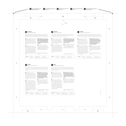
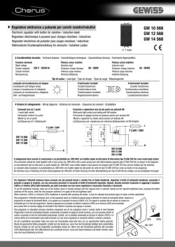


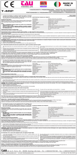

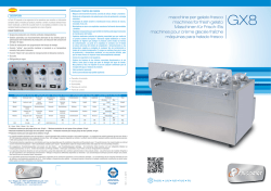
© Copyright 2026