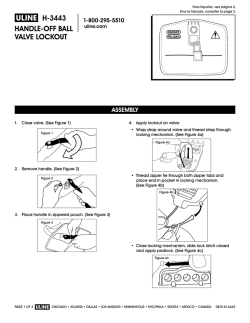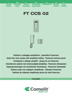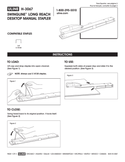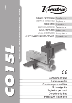
Butterfly valve Vanne papillon Válvula de mariposa
®
Lluís Companys, 51-53 - 08400 Granollers (Barcelona) Spain
Tel. +(34) 93 870 42 08 - Fax +(34) 93 870 98 11
E-mail: [email protected] - Website: www.cepex.com
Butterfly valve
Vanne papillon
Válvula de mariposa
Characteristics
Caractéristiques
Características
Working pressure at 20°C (73°F) water temperature:
Pression de service à 20°C (73°F) température de
l`eau:
Presión de servicio a 20°C (73°F) temperatura de
agua:
- D315 PN 10 bar (150 p.s.i.)
- D315 PN 10 bar (150 p.s.i.)
- D315 PN 10 bar (150 p.s.i.)
10
8
Components / Composants / Componentes
1
5
4
Description / Description / Descripción
5
5
5
2
3
7
9
Material / Matière / Material
1.
2.
3.
4.
Body / Corps / Cuerpo
Valve disc / Papillon / Compuerta
Sealing gasket / Garniture du papillon / Junta compuerta
Shaft / Axe / Eje
5.
6.
7.
8.
9.
10.
O-Ring seal / Joints toriques de l’axe / Junta eje
Cap / Bouchon / Tapón
Screw / Vis / Tornillo
Bearing / Douille / Casquillo
Bearing / Douille / Casquillo
Gear box / Réducteur manuel / Reductor manual
PP + Fiber glass
PP / PVC-U / PVC-C / ABS
EPDM / FPM
AISI 316 Stainless Steel
or Zinc plated steel
EPDM / FPM
Noryl
Noryl
Aluminium
6
FRANÇAIS
ESPAÑOL
Operating instructions
Instructions d’utilisation
Instrucciones de utilización
To operate the valve turn the handle on the correct
sense.
Pour actionner la vanne, en tournant le réducteur.
Para accionar la válvula, se procederá a girar el
reductor en el sentido conveniente.
Accouplement
Coupling
Fig. 1
Acoplamiento
Avec les brides, normes DIN et normes ISO (selon
schéma de la fig. 1). Dans l’accouplement, les joints
plats pour les collets ne sont pas nécessaires
puisqu’ils sont incorporées à la vanne.
Mount valve between DIN or ANSI (supplied by
others) flanges as shown in Figure 1. Valve is
supplied with self-sealing gasket and requires no
additional rubber seal material. Follow flange
manufacturers bolt torque guidelines during fit-up.
Operations pour le changement de la garniture du
papillon
Operations for replacing the self-sealing gasket
Si la garniture du papillon doit être substitué, on
procedera de la façon suivante:
• Retirer le réducteur manuel.
• Enlever le joint élastique. Sortir le bouchon (6) et
enlever le vis (7).
• Taper sur l’axe (4) avec un maillet jusqu’à ce que
sorte la douille (9). (Schéma fig.2)
• Une fois la douille dehors, sortir l’axe (4), ensuite le
faire pivoter avant de le réintroduire (schéma fig.3)
par dessous.
• Continuer à taper jusqu’à ce que sorte la douille (8),
recommencer à sortir l’axe.
• Maintenant vous pouvez extraire la garniture et le
joint. Enfin les remplacer par des nouveaux.
If the disc (2) or self-sealing gasket (3) are to be
replaced, remove handle (9) as above and proceed
as follows:
• Remove the bottom plug (6), loosen and remove
screw (12) and O-ring (10).
• Tap top of shaft (4) with a rubber mallet until Noryl
sleeve (15) is exposed and can be removed from
bottom as seen in figure 2.
• Remove shaft (4) from valve body; invert shaft (4)
and re-insert from bottom of valve body as seen in
figure 3.
• Tap shaft (4) with rubber mallet until Noryl sleeve
(11) is exposed and can be removed.
• Remove disc (2) and self-sealing gasket (3). Follow
reverse procedure to re-assemble valve.
Operaciones para el recambio de la junta de la
compuerta
En caso de que fuera necesario cambiar la junta de la
válvula, se procederá de la siguiente manera:
• Extraer el reductor manual.
• Quitar el anillo elástico . Sacar el tapón (6) y quitar
el tornillo (7).
• Picar sobre el eje (4) con una maza de nylon hasta
que salga el casquillo (9) por debajo. (Esquema fig.2).
• Con el casquillo fuera, sacar el eje (4), rotarlo y
volver a introducirlo por debajo (esquema fig.3).
• Seguir picando hasta que salga el casquillo (8) por
encima, volver a sacar el eje.
• Ahora se está en disposición de extraer la
compuerta y la junta. Sustituir por una nueva.
Relative flow chart
Diagramme de flux relatif
Diagrama de flujo relativo
Fig. 2
Kv
Mediante bridas Normas DIN y Normas ISO
(esquema fig. 1). En el acoplamiento no son
necesarias juntas planas para los manguitos, por
llevarlas incorporadas la misma válvula.
%
Torque graph
Diagramme de couple
Diagrama de par
Nm
340
100
320
300
90
D
80
Kv100
Cv
78571
5500
280
260
240
70
315
12”
220
200
60
180
50
160
140
40
120
30
100
Cv = Kv100 / 14,28
Kv100 (l/min, p = 1 bar)
Cv (GPM, p = 1 p.s.i.)
20
10
80
60
40
20
20
30
40
50
60
70
80
90
100
315
12”
Fig. 3
Pressure loss diagram
Diagramme de perte de charge
Diagrama de pérdidas de carga
Pressure / temperature graph
Diagramme pression / température
Diagrama presión / temperatura
m.c.a.
270 18
Pressure / Pression / Presión
240 16
210 14
180 12
150 10
120
8
90
6
60
4
30
2
0
0
PN 10
0
32
10
50
20
68
30
86
40
104
50
122
60
140
°C
°F
Pressure loss / Perde de charge / Pérdida de carga
p.s.i.bar
”)
10
% opening / % d’ouverture / % de apertura
D3
15
(1
2
0
10
1
0,1
V = 2m/s
0,01
0,01
0,1
1
2
m³/s
Flow / Débit / Caudal
Temperature / Température / Temperatura
• WE RESERVE THE RIGHT TO CHANGE ALL OR PART OF THE FEATURES OF THE
ARTICLES OR CONTENTS OF THIS DOCUMENT, WITHOUT PRIOR NOTICE.
• NOUS NOUS RÉSERVONS LE DROIT DE MODIFIER TOTALEMENT OU EN PARTIE
LES CARACTERISTIQUES DE NOS ARTICLES OU LE CONTENU DE CE DOCUMENT
SANS PRÉ-AVIS.
• NOS RESERVAMOS EL DERECHO DE CAMBIAR TOTAL O PARCIALMENTE LAS
CARACTERISTICAS DE NUESTROS ARTICULOS O CONTENIDO DE ESTE DOCUMENTO
SIN PREVIO AVISO.
EDICIÓN: DICIEMBRE 2004 - D. L. B.XXXXXXXXX - COPYRIGHT © CEPEX HOLDING, S.A. - ALL RIGHTS RESERVED
ENGLISH
© Copyright 2026
