
Sch./Ref./Typ/Ref. 1092/705 Mod. 1092
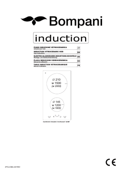
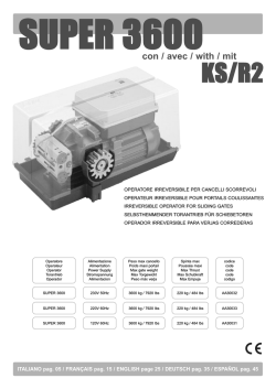
Mod. 1092 DS1092-122 POWER BOX COFFRET D’ALIMENTATION CAJA DE CONEXIONES Sch./Ref./Typ/Ref. 1092/705 MANUALE D’USO USER MANUAL MANUEL UTILISATEUR GEBRAUCHSANLEITUNG MANUAL DE USUARIO ITALIANO INFORMAZIONI GENERALI Caro cliente La ringraziamo per l’acquisto di questo prodotto. Il presente documento descrive come utilizzare il Power Box URMET Domus S.p.A. Sch. 1092/705. Prima di utilizzare l’apparecchiatura, leggere il presente manuale che ne descrive l’uso corretto e sicuro. Conservare questo manuale con attenzione ed in un luogo facilmente reperibile per poterlo consultare prontamente quando necessario. DESCRIZIONE PRODOTTO E TIPO DI IMPIEGO Il Power Box Sch.1092/705 è certificato IP66, quindi progettato per essere impiegato sia in interni che in esterni. L’involucro metallico contiene l’alimentatore per la Dome e la scheda di allarmi a 8 ingressi programmabili. Per mezzo della programmazione interna della dome, è possibile scegliere la gestione degli allarmi disponibili: da 1 a 8 o da 9 a 16 (funzione disponibile solo con impiego dei modelli Sch.1092/674, Sch.1092/675 e Sch.1092/676). E’anche possibile, in caso di allarme, l’invio di Preset precedentemente memorizzati sulla dome (da 1 a 8, da 9 a 16 e da 41 a 48). Nota Bene Il prodotto URMET Domus S.p.A. Sch.1092/705 è destinato ad impianti TVCC Caratteristiche generali Involucro metallico certificato IP66. Utilizzabile sia in interni che in esterni. Collocabile sia su parete che su soffitto. APERTURA DELLA CONFEZIONE Verificare che l’imballo ed il contenuto non presentino danni visibili. Se alcune parti non sono presenti o risultano danneggiate, contattare immediatamente il rivenditore. In questi casi non tentare di utilizzare il dispositivo. Se il prodotto dovesse essere rimandato al fornitore, assicurarsi di spedirlo con il suo imballo originale. Contenuto della confezione N°1 Power Box N°1 Manuale d’uso Nota Bene La composizione degli accessori a corredo può essere variata senza alcun preavviso. AVVERTENZE Alimentazione Questo dispositivo deve essere alimentato esclusivamente con tensione di rete pari a 230Vca. Precauzioni per la sicurezza Evitare di introdurre al suo interno qualsiasi oggetto solido o liquido. Se ciò dovesse avvenire scollegare immediatamente il dispositivo dalla rete di alimentazione e farlo controllare da personale qualificato. Per qualsiasi intervento di riparazione rivolgersi a personale qualificato oppure contattare il centro assistenza tecnico autorizzato. Non toccare questa apparecchiatura con le mani bagnate per evitare rischi di scosse elettriche. 2 DS1092-122 Precauzioni per l’utilizzo Non usare questa apparecchiatura in ambienti con presenza di fumo, vapore, umidità o polveri intense. Non mettere in funzione il dispositivo immediatamente dopo il trasporto da un luogo freddo ad uno caldo e viceversa. Attendere mediamente tre ore: questo intervallo di tempo è necessario al dispositivo per adattarsi al nuovo ambiente (temperatura, umidità, ecc…). Pulizia del dispositivo Usare un panno asciutto e strofinare leggermente per eliminare polvere e sporcizia. Nel caso in cui la sporcizia non fosse eliminabile con un panno asciutto, compiere l’operazione con un panno leggermente inumidito con un detergente neutro. Non usare liquidi volatili come benzina, alcool, solventi ecc. o panni trattati chimicamente per pulire il dispositivo al fine di evitare deterioramenti o graffi della finitura della vernice. COMANDI E REGOLAZIONI Qui di seguito, vengono riportate le tabelle relative alle regolazioni dei dip-switch presenti sulla scheda di allarme contenuta nel Power Box. COLLEGAMENTO TASTIERA COLLEGAMENTO DOME Allarme 1 NA Allarme 5 NA Allarme 2 NA Allarme 6 NA Allarm e3 NA Allarme 7 NA Allarme 4 NA Allarme 8 NA DS1092-122 3 DIP SW 1 (INDIRIZZO DOME) Switch NO. Indirizzo 0 1 2 3 4 5 6 7 8 9 10 11 12 13 14 15 ---255 1 2 3 4 5 6 7 8 OFF ON OFF ON OFF ON OFF ON OFF ONF OFF ON OFF ON OFF ON OFF OFF ON ON OFF OFF ON ON OFF OFF ON ON OFF OFF ON ON OFF OFF OFF OFF ON ON ON ON OFF OFF OFF OFF ON ON ON ON OFF OFF OFF OFF OFF OFF OFF OFF ON ON ON ON ON ON ON ON OFF OFF OFF OFF OFF OFF OFF OFF OFF OFF OFF OFF OFF OFF OFF OFF OFF OFF OFF OFF OFF OFF OFF OFF OFF OFF OFF OFF OFF OFF OFF OFF OFF OFF OFF OFF OFF OFF OFF OFF OFF OFF OFF OFF OFF OFF OFF OFF OFF OFF OFF OFF OFF OFF OFF OFF OFF OFF OFF OFF OFF OFF OFF OFF ON ON ON ON ON ON ON ON DIP SW 2 (PROTOCOLLO DI COMUNICAZIONE – BAUD RATE) Protocollo Switch NO Protocollo PELCO-D Baud rate 1 2 3 4 ON ON OFF OFF Baud rate 2400bps 4800bps 9600bps 19200bps 5 6 7-8 OFF OFF ON ON OFF ON OFF ON DIP SW 3 (SELEZIONE TIPO DI CONTATTO – NA/NC) Switch NO/Sensore Normalmente APERTO Normalmente CHIUSO 1 2 3 4 5 6 7 8 ON ON ON ON ON ON ON ON OFF OFF OFF OFF OFF OFF OFF OFF Nota Bene Ciascun dip-switch corrisponde a uno degli otto ingressi di allarme disponibili (1 – 8). 4 DS1092-122 DIP SW 4 (NUMERO PB – TEMPO RITARDO ALLARME) SELEZIONE TIPO DI ALLARMI/PRESET TIPO Dip-switch 1 2 3 1 OFF OFF OFF 2 ON OFF OFF 3 OFF ON OFF 4 ON ON OFF 5 OFF OFF ON 6 ON OFF ON 7 OFF ON ON 8 ON ON ON TEMPO DI RITARDO ALLARME Ritardo in Sec. Dip-switch 4 5 3S OFF OFF 6S ON OFF 9S OFF ON I dip-switch 1 – 2 – 3 selezionano il tipo di allarmi/preset gestiti dal Power Box. Tipo 1 e 2 solo per EASY IV: Tipo 1 : rilevazione allarmi dal N° 1 al N° 8 Tipo 2 : rilevazione allarmi dal N° 9 al N° 16 Tipo dal 3 al 8 : per qualsiasi tipo di Speed Dome (riferirsi alla programmazione allarmi manuali). Tipo 3 : invio preset da 1 a 8 I dip-switch 4 e 5 selezionano l’intervallo di tempo minimo tra due azioni di allarme consecutivi. Nota Bene Le operazioni di impostazione dei Dip-switch devono essere eseguite con i dispositivi scollegati dalla tensione di rete. DS1092-122 5 POSIZIONAMENTO Individuato il punto dove installare la telecamera, procedere nel seguente modo: Eseguire i fori di fissaggio secondo il tipo di parete (cemento, legno, ecc) e predisporre i dispositivi di fissaggio impiegati (tasselli viti ecc.). Fissare il Power Box di collegamento alla superficie. Aprire il Power Box svitando le quattro viti poste sugli angoli dello sportello. Inserire nei passacavi tutti i cavi necessari al corretto funzionamento della telecamera. Per installazioni all’esterno, prestare attenzione ad effettuare una buona chiusura dei passacavi per garantire il mantenimento del grado di protezione IP. Collegare l’alimentazione di rete ai morsetti dedicati rimuovendo il coperchio di protezione da riposizionare dopo aver eseguiti i collegamenti, ma non alimentare il Power Box sino ad installazione terminata. Collegare la linea seriale RS485 ai morsetti AA BB Collegare i cavi relativi ai sensori di allarme sui morsetti 1 e 8 di ingresso allarme. Connettere il cavo video proveniente dal dispositivo video utilizzato (DVR, Monitor, ecc.) al connettore BNC femmina posto all’interno del box, avendo cura di posizionare la guaina plastica di protezione della parti metalliche affinché queste non possano andare a contatto con le parti elettroniche interne. Configurare i vari dip-switch del Power Box. Richiudere il Power Box con le viti precedentemente tolte per l’apertura prestando attenzione a non pizzicare i cavi al suo interno. Proseguire con l’installazione della dome seguendo le istruzioni contenute nella confezione della telecamera. 6 DS1092-122 CARATTERISTICHE TECNICHE Ingresso alimentazione:.....................................................................................................230Vca 50Hz 50VA Temperatura di utilizzo: ................................................................................................................. -20 ÷ +60°C Temperatura d’immagazzinamento: .............................................................................................. -30 ÷ +60°C Grado di protezione: .................................................................................................................................. IP66 Dimensioni (L x H x P):...................................................................................................... 165 x 140 x 95 mm Peso: .................................................................................................................................................... 2150gr. Nota Bene Le caratteristiche tecniche possono essere soggette a variazione senza alcun preavviso. DS1092-122 7 ENGLISH GENERAL INFORMATION Dear Customer, Thank your for purchasing this product. This document shows how to install and use the Power Box URMET Domus S.p.A. Sch.1092/705. Read this manual which contains information for correct, safe use carefully. Keep this manual at hand so that you can refer to it when needed. PRODUCT DESCRIPTION AND TYPE OF USE The Power Box Ref.1092/705 is IP66 certified and designed for indoor and outdoor use. The metallic housing contains the power supply for the Dome and the alarm card with 8 programmable inputs. By internal programming of the dome, it is possible to select the management of the available alarms: from 1 to 8 or from 9 to 16 (function available with models Ref. 1092/674, Ref.1092/675 and Ref.1092/676 only). In case of alarm, it is also possible to send a Preset previously stored in the dome (from 1 to 8, from 9 to 16 and from 41 to 48). Note The product URMET Domus S.p.A. Ref.1092/705 is designed for use in CCTV systems General characteristics IP66 certified metallic housing. For indoor and outdoor use. Ceiling or wall installation. Opening the box Check that the packing and the contents are not visibly damaged. Contact the retailer immediately if parts are either missing or damaged. Do not attempt to use the device in this case. Send the product back in its original packing if it is damaged. Contents of the box N° 1 Power Box N° 1 Instructions manual IMPORTANT NOTE Accessories may be changed without prior notice. 8 DS1092-122 IMPORTANT SAFETY NOTES Power supply This device must be powered exclusively by 230Vca mains voltage. SAFETY PRECAUTIONS Avoid introducing any object or liquid into the device. If this should accidentally occur, disconnect the device from the mains and have it inspected by qualified personnel. For any repairing, contact skilled staff or our authorized technical service. Do not touch this device with wet hands, in order to avoid electric hazard. INSTALLATION PRECAUTIONS Wait for a while before operating a device immediately after transporting it from a cold place to a warm place and vice versa. Wait on average for three hours: this will allow the device to adapt to the new ambient (temperature, humidity, etc.). Do not use this device in smoky, steamy, damp or dusty environments. CLEANING THE DEVICE Rub delicately with a dry cloth to remove dust and dirt. Dip the cloth in neutral detergent if dirt cannot be eliminated with a dry cloth alone. Do not use volatile liquids (such as petrol, alcohol, solvents, etc.) or chemically treated clothes to clean the device to prevent deformation, deterioration or scratches to the surface finish. DS1092-122 9 COMMANDS AND SETTINGS The following tables show the settings of the dip-switches present on the alarm card in the power box. KEYBOAR CONNECTION DOME CONNECTION 10 Alerm 1 NO Alarm 5 NO Alarm 2 NO Alarm 6 NO Alarm 3 NO Alarm 7 NO Alarm 4 NO Alarm 8 NO DS1092-122 DIP SW 1 (DOME ADDRESS) Switch Nr. Address 0 1 2 3 4 5 6 7 8 9 10 11 12 13 14 15 ---255 1 2 3 4 5 6 7 8 OFF ON OFF ON OFF ON OFF ON OFF ONF OFF ON OFF ON OFF ON OFF OFF ON ON OFF OFF ON ON OFF OFF ON ON OFF OFF ON ON OFF OFF OFF OFF ON ON ON ON OFF OFF OFF OFF ON ON ON ON OFF OFF OFF OFF OFF OFF OFF OFF ON ON ON ON ON ON ON ON OFF OFF OFF OFF OFF OFF OFF OFF OFF OFF OFF OFF OFF OFF OFF OFF OFF OFF OFF OFF OFF OFF OFF OFF OFF OFF OFF OFF OFF OFF OFF OFF OFF OFF OFF OFF OFF OFF OFF OFF OFF OFF OFF OFF OFF OFF OFF OFF OFF OFF OFF OFF OFF OFF OFF OFF OFF OFF OFF OFF OFF OFF OFF OFF ON ON ON ON ON ON ON ON DIP SW 2 (COMMUNICATION PROTOCOL – BAUD RATE) Protocol Switch Nr. Protocol PELCO-D Baud rate 1 2 3 4 ON ON OFF OFF Baud rate 2400bps 4800bps 9600bps 19200bps 5 6 7-8 OFF OFF ON ON OFF ON OFF ON DIP SW 3 (CONTACT TYPE SELECTION – NO/NC) Switch Nr/Sensor Normallly OPEN Normallly CLOSED 1 ON OFF 2 ON OFF 3 ON OFF 4 ON OFF 5 ON OFF 6 ON OFF 7 ON OFF 8 ON OFF Note Every dip-switch represents one of the eight available alarm inputs (1 – 8). DS1092-122 11 DIP SW 4 (PB NUMBER – ALARM DELAY TIME) Power Box 1 2 3 4 5 6 7 8 ACTIONS Dip-switch 1 2 OFF OFF ON OFF OFF ON ON ON OFF OFF ON OFF OFF ON ON ON 3 OFF OFF OFF OFF ON ON ON ON ALARM DELAY TIME Delay in Sec. Dip-switch 4 5 3S OFF OFF 6S ON OFF 9S OFF ON The dip-switches 1 – 2 – 3 select the alarm/preset type managed by Power Box. Type 1 and 2 for EASY IV only. Type 1 : alarm detection from nr. 1 to nr. 8. Type 2: alarm detection from nr. 9 to nr. 16. Type from 3 to 8: for any Speed Dome kind (refer to manual alarms programming procedure). Type 3: preset sending from 1 to 8. The dip-switches 4 and 5 select the minimum time between two consecutive alarm actions. Note The Dip-switch setting operations must be performed when the devices are unpowered. 12 DS1092-122 INSTALLATION After the place where to install the camera is found, follow the instructions below: Make the fixing holes according to the wall type (cement or wood) and prepare the fixing devices (screw anchors, screws, etc.) Fix the connection Power Box to the surface. Open the Power Box by unscrewing the four screws on the cover corners. Insert in the wire grommets all the cables needed for the correct operation of the camera. For outdoor installations, pay attention to close hermetically the wire grommets, in order to maintain the IP protection grade. Connect the dedicated terminal pins to the mains by removing the protection cover, that must be positioned back again after making the connections, but do not power the Power Box until the installation has been completed. Connect the RS485 serial line to AA BB terminal pins. Connect the alarm sensors cables to the alarm input terminal pins 1 and 8. Connect the video cable from the video device in use (DVR, monitor, etc.) to the female BNC connector placed inside the box, taking care to put the rubber sheath for the protection of the metallic parts, in order to avoid that these ones make electrical contact with internal electronic parts. Configure the different Power Box dip-switches. Close again the Power Box with the screws previously removed to open it, taking care not to pinch the cables inside. Keep on installing the dome, following the instructions present on the camera package. DS1092-122 13 TECHNICAL CHARACTERISTICS Power supply input: ...........................................................................................................230Vca 50Hz 50VA Working temperature range:.......................................................................................................... -20 ÷ +60°C Storage temperature range: .......................................................................................................... -30 ÷ +60°C Protection grade: ....................................................................................................................................... IP66 Dimensions (L x H x D):..................................................................................................... 165 x 140 x 95 mm Weight: ................................................................................................................................................. 2150gr. Note Technical characteristics may be modified without notice. 14 DS1092-122 FRANÇAIS DESCRIPTION DU PRODUIT ET TYPE D’UTILISATION Le coffret métallique étanche contient l’alimentation pour le dôme Thera5 – Easy /// et une carte d’interface pour 8 alarmes. Il est possible avec cette carte d’appeler des prépositions enregistrées dans le dôme en cas de changement d’état des entrées. Ces prépositions doivent se suivre séquentiellement (de 1 à 8, 9 à 16, jusqu’à 41 à 48). Ce coffret Réf.1092/705 est IP66 et peut être utilisée en intérieur et extérieur. Note Les caractéristiques techniques et les accessoires peuvent être modifiés sans préavis. TYPE D’ALIMENTATION Cet appareil doit être exclusivement alimenté en 230 Volts alternatif SPECIFICATIONS D’INSTALLATION Ne pas pointer directement la camera vers le soleil ou une source de lumière vive. Eviter les situations avec un contre jour, ou les sujets éclairés par l’arrière Certaines sources lumineuses comme les éclairages fluorescents peuvent perturber l’équilibre des couleurs. Installez une protection par fusibles en amont de l’appareil. Vérifiez que l’alimentation installée est du bon type : tension, puissance PRECAUTIONS D’INSTALLATION Pour éviter la surchauffe du dôme, placez-le dans un endroit aéré. Pour la même raison, ne pas installer près de sources de chaleur actives (radiateurs), ou exposé directement aux rayonnements solaires. Evitez également les endroits poussiéreux, soumis à des vibrations excessives ou à des chocs répétés. Ne perdez pas de vue les conditions environnementales pour un bon fonctionnement (-10°C÷+50°C) AVANT l’installation. Ne mettez jamais en route le dôme si vous le déplacez d’un endroit froid à un endroit chaud. Laissez le s’adapter aux nouvelles conditions (température, humidité) pendant au moins trois heures. NETTOYAGE DU MINIDOME Nettoyer avec un chiffon sec pour enlever la poussière et la boue. N’utiliser que de l’eau ou un détergent neutre en cas de taches. Un chiffon mouillé étant la meilleure solution. N’utilisez jamais de liquides volatiles : alcool, solvant ou de chiffons pré-imprégnés pour éviter déformation, rayures, etc.… DS1092-122 15 PARAMETRAGE DE LA CARTE DE GESTION VERS LE COMMANDE CLAVIER DE VERS LE DÔME DIP SW 1 (ADRESSAGE DU DÔME) Switch Nr. 1 2 3 4 5 Adressage 0 OFF OFF OFF OFF OFF 1 ON OFF OFF OFF OFF 2 OFF ON OFF OFF OFF 3 ON ON OFF OFF OFF 4 OFF OFF ON OFF OFF 5 ON OFF ON OFF OFF 6 OFF ON ON OFF OFF 7 ON ON ON OFF OFF 8 OFF OFF OFF ON OFF 9 ONF OFF OFF ON OFF 10 OFF ON OFF ON OFF 11 ON ON OFF ON OFF 12 OFF OFF ON ON OFF 13 ON OFF ON ON OFF 14 OFF ON ON ON OFF 15 ON ON ON ON OFF ---255 ON ON ON ON ON L’adresse 0 (zéro) est interdite dans les protocoles de commande 16 6 7 8 OFF OFF OFF OFF OFF OFF OFF OFF OFF OFF OFF OFF OFF OFF OFF OFF OFF OFF OFF OFF OFF OFF OFF OFF OFF OFF OFF OFF OFF OFF OFF OFF OFF OFF OFF OFF OFF OFF OFF OFF OFF OFF OFF OFF OFF OFF OFF OFF ON ON ON DS1092-122 DIP SW 2 (CHOIX DU PROTOCOLE ET VITESSE) Switch Nr. Protocol PELCO-D Choix du protocole 1 2 ON ON 3 4 OFF OFF Vitesse 2400bps 4800bps 9600bps 19200bps 5 Vitesse 6 OFF OFF ON ON OFF ON OFF ON 7-8 DIP SW 3 (ETAT LOGIQUE DES ENTREES) Switch Nr/Sensor Normalement Ouvert NO Normalement Fermé NF 1 ON OFF 2 ON OFF 3 ON OFF 4 ON OFF 5 ON OFF 6 ON OFF 7 ON OFF 8 ON OFF Note Chacun des Switch représente une des huit entrées (1 – 8). DIP SW 4 (SELECTION DES PREPOSITIONS ET DELAI ENTRE ALARMES) CHOIX DU TYPE DE PREPOSITIONS Power Box Dip-switch 1 2 3 1 OFF OFF OFF 2 ON OFF OFF 3 OFF ON OFF 4 ON ON OFF 5 OFF OFF ON 6 ON OFF ON 7 OFF ON ON 8 ON ON ON TEMPO ENTRE ALARMES Delay in Sec. Dip-switch 4 5 3S OFF OFF 6S ON OFF 9S OFF ON Les Switch 1 – 2 – 3 déterminent le type de prépositions gérés par la carte d’alarme. Les types 1-2 ne s'appliquent qu'aux modèles EASY IV. Type 1: détection des alarmes 1 à 8 Type 2: détection des alarmes 9 à 16 Les types 3 à 8: pour tout modèle de Speed Dome (voir programmation manuelle des alarmes) -Type 3: rappel des prépositions 1 à 8 Les Switch 4 et 5 permettent de choisir un temps minimum entre deux sauts de prépositions suite à alarmes. Note TOUS CES REGLAGES DE SWITCHS DOIVENT S’EFFECTUER AVEC LE DOME HORS TENSION. DS1092-122 17 Installation TYPE Après avoir localisé le lieu d'installation de la caméra procéder comme suit : Réaliser les orifices de fixation selon le type de paroi (béton, bois, etc.) et préparer les dispositifs de fixation utilisés (chevilles, vis, etc.). Fixer le boîtier de connexion à la paroi, en veillant à diriger toujours les passe-câbles vers le bas. Ouvrir le Power Box, en dévissant les quatre vis situées sur les angles du volet. Introduire dans les passe-câbles tous les câbles nécessaires au fonctionnement correct de la caméra. Pour les installations en extérieur, veiller à assurer une parfaite fermeture des passecâbles pour préserver le degré de protection IP. Raccorder l’alimentation secteur sur les bornes dédiées (il est nécessaire de déposer la protection transparente, puis de la reposer une fois les branchements réalisés), mais attendre que l’installation soit achevée avant d’alimenter le Power Box. Brancher le câble série de la ligne RS-485 du clavier (livré de série avec ce dernier) sur les bornes AA BB. Brancher les câbles des capteurs d’alarme sur les bornes 1 et 8 d’entrée alarme Brancher le câble vidéo en provenance du dispositif vidéo utilisé (DVR, Moniteur, etc.) sur le connecteur BNC femelle situé dans le boîtier, en veillant à positionner la gaine de protection en plastique des parties métalliques de manière à éviter leur contact avec les parties électroniques intérieures. Configurer les différents commutateurs du Power Box Refermer le Power Box en utilisant les vis précédemment retirées et en contrôlant visuellement l’étanchéité. 18 DS1092-122 CARACTERISTIQUES TECHNIQUES Alimentation:......................................................................................................................230Vca 50Hz 50VA Température de fonctionnement: .................................................................................................. -20 ÷ +60°C Température de stockage: ............................................................................................................ -30 ÷ +60°C Indice de Protection:.................................................................................................................................. IP66 Dimensions (L x H x P):..................................................................................................... 165 x 140 x 95 mm Poids:.................................................................................................................................................... 2150gr. Note Les caractéristiques techniques et les accessoires peuvent être modifiés sans préavis. DS1092-122 19 DEUTSCH ALLGEMEINE INFORMATIONEN Sehr geehrter Kunde, vielen Dank fűr den Kauf dieses Urmet Produkts. Dieses Dokument beschreibt die Installation und die Verwendung der Power Box Typ 1092/705. Vor der Installation des Zubehörteiles diese Anleitung lesen, die dessen korrekten und sicheren Gebrauch beschreibt. Diese Gebrauchsanleitung sorgsam und an einem leicht zugänglichen Ort aufbewahren, um sie bei Bedarf umgehend konsultieren zu können. PRODUKTBESCHREIBUNG UND DESSEN NUTZUNG Die Power Box Typ1092/705 ist IP66 zertifiziert und für Innen- und Außenanwendungen konstruiert. Das Metallgehäuse enthält die Spannungsversorgung und eine Alarmkarte mit 8 programmierbaren Eingängen. Bei interner Programmierung des Domes, ist es möglich die Auswahl der vorhandenen Alarme zu verwalten: von 1 bis 8 oder von 9 bis 16 (Funktion vorhanden bei den Modellen Typ 1092/674, Typ1092/675 and Typ1092/676). Im Falle eines Alarms, ist es möglich einen Preset zu senden der vorher im Dome gespeichert worden ist (von 1 bis 8, von 9 bis 16 und von 41 bis 48). BEACHTEN Das Produkt URMET Domus S.p.A. Typ 1092/705 wurde zur Nutzung in CCTV-Systemen konsturiert. Allgemeine Merkmale IP66 zertifiziertes Metallgehäuse. Für Innen- und Außenanwendungen. Wand- oder Deckeninstallation. ÖFFNEN DER VERPACKUNG Überprüfen, ob die Verpackung und der Inhalt keine erkennbaren Schäden aufweisen. Fehlen Teile oder erweisen diese sich als beschädigt, unmittelbar den Händler kontaktieren. In diesen Fällen nicht versuchen, das Zubehörteil zu verwenden. Sollte das Produkt an den Lieferanten zurückgeschickt werden, vergewissern Sie sich, dass dies in der Originalverpackung erfolgt. Inhalt der Verpackung 1 Power Box 1 Gebrauchsanleitung BEACHTEN Die im Lieferumfang enthaltenen Zubehörteile können ohne Vorankündigung geändert werden 20 DS1092-122 WARNHINWEISE SPANNUNGSVERSORGUNG Dieses Gerät darf ausschließlich mit einer Spannung von 230V AC betrieben werden. SICHERHEITSHINWEISE Vermeiden Sie es, das Gerät Regen oder Feuchtigkeit auszusetzen, um einer Brandgefahr und Stromschlägen vorzubeugen. Keine Fremdkörper oder Flüssigkeiten in das Geräteinnere gelangen lassen. Sollte dies dennoch geschehen, das Gerät vom Stromnetz trennen und von Fachpersonal kontrollieren lassen. Wenden Sie sich im Reparaturfall an einen ausgebildeten Fachmann oder kontaktieren Sie das autorisierte Kundendienstzentrum. Um Stromschläge und mechanische Beschädigungen zu vermeiden, Gerät nicht mit nassen Händen anfassen. VORSICHSMASSNAHMEN BEI DER INSTALLATION Gerät nicht unmittelbar nach dem Transport von einem kühlen an einen warmen Ort oder umgekehrt in Betrieb nehmen. Im Durchschnitt sind drei Stunden abzuwarten: dieser Zeitraum ist erforderlich, damit das Gerät sich an die neue Umgebung anpassen kann (Temperatur, Feuchtigkeit, etc.). Gerät nicht in Umgebungen verwenden, in denen Rauch, Dampf, Feuchtigkeit oder Staub vorhanden sind. REINIGUNG DES GERÄTS Um Staub und Schmutz zu entfernen, Gerät mit einem trockenen Tuch abreiben. Sollte der Schmutz mit einem trockenen Tuch nicht zu entfernen sein, Gerät mit einem feuchten Lappen und Neutralreiniger abwischen. Um Verformungen, Beschädigungen oder Kratzer im Lack zu verhindern, keine flüchtigen Flüssigkeiten wie Benzin, Alkohol, Lösungsmittel etc. oder chemisch behandelte Tücher zur Reinigung des Geräts verwenden. DS1092-122 21 EINSTELLUNGEN Die folgende Ansicht (Abb. 1) zeigt eine Übersicht der Anschlussklemmen und der DIP-Schalter, die auf der im Deckel der Power-Box befindlichen Platine zur Verfügung stehen. RS485-ANSCHLUSS TASTATUR RS485-ANSCHLUSS DOME Alarm 1 NO Alarm 5 NO Alarm 2 NO Alarm 6 NO Alarm 3 NO Alarm 7 NO Alarm 4 NO Alarm 8 NO Abb.1 22 DS1092-122 DIP SCHALTER 1 (ADRESSE DOME) Schalter Nr. Adresse 0 1 2 3 4 5 6 7 8 9 10 11 12 13 14 15 ---255 1 2 3 4 5 6 7 8 OFF ON OFF ON OFF ON OFF ON OFF ONF OFF ON OFF ON OFF ON OFF OFF ON ON OFF OFF ON ON OFF OFF ON ON OFF OFF ON ON OFF OFF OFF OFF ON ON ON ON OFF OFF OFF OFF ON ON ON ON OFF OFF OFF OFF OFF OFF OFF OFF ON ON ON ON ON ON ON ON OFF OFF OFF OFF OFF OFF OFF OFF OFF OFF OFF OFF OFF OFF OFF OFF OFF OFF OFF OFF OFF OFF OFF OFF OFF OFF OFF OFF OFF OFF OFF OFF OFF OFF OFF OFF OFF OFF OFF OFF OFF OFF OFF OFF OFF OFF OFF OFF OFF OFF OFF OFF OFF OFF OFF OFF OFF OFF OFF OFF OFF OFF OFF OFF ON ON ON ON ON ON ON ON DIP SCHALTER 2 (KOMMUNIKATIONSPROTOKOLL – BAUD RATE) Protokoll Schalter Nr. Protokoll PELCO-D Baud Rate 1 2 3 4 ON ON OFF OFF Baud Rate 2400bps 4800bps 9600bps 19200bps 5 6 7-8 OFF OFF ON ON OFF ON OFF ON DIP SCHALTER 3 (AUSWAHL KONTAKTTYP – NO/NC) Schalter Nr./Sensor Normal OFFEN Normal GESCHLOSSEN 1 2 3 4 5 6 7 8 ON ON ON ON ON ON ON ON OFF OFF OFF OFF OFF OFF OFF OFF BEACHTEN Jeder DIP-Schalter bezieht sich auf einen der acht Alarmeingänge (1 – 8). DS1092-122 23 DIP SCHALTER 4 (PB NUMMER – ALARM VERZÖGERUNGSZEIT) AKTION DIP-Schalter TYP 1 2 3 4 5 6 7 8 1 OFF ON OFF ON OFF ON OFF ON 2 OFF OFF ON ON OFF OFF ON ON 3 OFF OFF OFF OFF ON ON ON ON ALARM VERZÖGERUNGSZEIT Verzög. in DIP-Schalter Sek. 4 5 3S OFF OFF 6S ON OFF 9S OFF ON Die DIP-Schalter 1 – 2 – 3 selektieren den Alarm/Preset der von der Power Box verwaltet wird. Typ 1 und 2 nur für EASY IV. Typ 1 : Alarmerkennung von Nr. 1 bis Nr. 8. Typ 2: Alarmerkennung von Nr. 9 bis Nr. 16. Typ von 3 bis 8: für andere Speed Dome Sorten (siehe Anleitung Programmierung der Alarme). Typ 3: Sendung Preset von 1 bis 8. Die DIP-Schalter 4 und 5 selektieren die minimale Zeit zwischen zwei aufeinanderfolgende Alarmaktionen. BEACHTEN Die Einstellungen der DIP-Schalter sollte im spannungslosen Zustand des Domes ausgeführt werden! 24 DS1092-122 INSTALLATION Nachdem die korrekte Position zur Installation der Komponenten gefunden wurde, folgen Sie den unten aufgeführten Anweisungen: Herstellen der Befestigungslöcher gemäß der vorhandenen Wand (z. B. Beton oder Holz) und der darauf zu befestigenden Geräte. Befestigung der Power Box auf der gewählten Oberfläche. Öffnen der Power Box durch Lösen der vier Schrauben des Deckels. Einführen der für den ordnungsgemäßen Betrieb des benötigten Anschlusskabel, durch die Verschraubungen. Bei der Außeninstallation, bitte die Verschraubungen so festziehen, damit der angegebene Schutzgrad erreicht wird. Abnehmen der Schutzabdeckung von den Versorgungsklemmen, Spannungsversorgung anschließen, Schutzabdeckung wieder befestigen. Bitte keine Spannung anlegen, bevor nicht alle Anschlüsse hergestellt und alle DIP-Schalter konfiguriert worden sind. Anschluss der seriellen Linie RS485 an die Klemmen AA und BB. Anschluss der Kabel für die Alarme an den Eingangsklemmen 1 bis 8. Anschluss des Videokabels (DVR, Monitor, etc.) an die in der Power Box befindlichen BNC-Buchse. Beachten: Nach Anschluss des Videokabels ist die Schutzkappe komplett über die Verbindung zu schieben, damit es nicht zu ungewollten Verbindungen (Kurzschlüssen) durch die BNC-Verbindung auf den in der Power-Box befindlichen Platinen kommt. Konfigurieren der DIP-Schalter in der Power Box. Den Deckel der Power Box schließen, dabei darauf achten das keine Kabel oder Adern eingequetscht werden. Installieren des Domes, nach den in der Verpackung des Domes enthaltenen Anweisungen. DS1092-122 25 TECHNISCHE EIGENSCHAFTEN Eingang Versorgungsspannung: .....................................................................................230V AC 50Hz 50VA Betriebstemperatur: ....................................................................................................................... -20 ÷ +60°C Lagertemperatur: ........................................................................................................................... -30 ÷ +60°C Schutzgrad: ............................................................................................................................................... IP66 Abmessungen (B x H x T): ................................................................................................ 165 x 140 x 95 mm Gewicht:................................................................................................................................................ 2150gr. BEACHTEN Technische Eigenschaften können ohne Vorankündigung geändert werden. 26 DS1092-122 ESPAÑOL INFORMACIÓN GENERAL Estimado cliente: Le agradecemos que haya comprado este producto. En este documento se describe cómo instalar y utilizar la caja de conexiones Ref. 1092/705 de URMET Domus S.p.A. Lea con atención este manual, ya que contiene información sobre el uso correcto y seguro de los dispositivos. Guarde el manual en un lugar fácilmente accesible para poder consultarlo cuando sea necesario. DESCRIPCIÓN DEL PRODUCTO Y UTILIZACIÓN La caja de conexiones Ref. 1092/705 tiene un grado de protección IP66 y está diseñada para funcionar en exterior o interior. La carcasa metálica contiene la fuente de alimentación del domo y la tarjeta de alarma de 8 entradas programables. Mediante programación interna del domo es posible gestionar las alarmas existentes: de 1 a 8 ó de 9 a 16 (función existente solo en los modelos Ref. 1092/674, Ref.1092/675 y Ref.1092/676). En caso de alarma, también puede enviarse una posición predefinida ya memorizada en el domo (de 1 a 8, de 9 a 16 y de 41 a 48). Nota: El producto Ref.1092/705 de URMET Domus S.p.A. está diseñado para sistemas CCTV. Características generales Carcasa metálica con grado de protección IP66. Funcionamiento en exterior o interior. Instalación en techo o pared. Comprobación del paquete Compruebe visualmente que el paquete y su contenido no presentan ningún daño. Si falta algún componente o está dañado, póngase en contacto con su distribuidor. En este caso, no intente utilizar el dispositivo. Si el producto presenta daños, devuélvalo en su embalaje original. Contenido del paquete 1 caja de conexiones 1 manual de instrucciones NOTA Los accesorios están sujetos a modificaciones sin previo aviso. DS1092-122 27 ADVERTENCIAS DE SEGURIDAD Alimentación Alimente este equipo únicamente con tensión eléctrica de 230 VCA. PRECAUCIONES DE SEGURIDAD Evite introducir objetos o sustancias líquidas en el equipo. Si esto se produjera de manera accidental, desconecte el equipo de la red eléctrica y haga que lo inspeccione personal cualificado. En caso de avería, póngase en contacto con personal cualificado o con nuestro servicio de asistencia técnica. No utilice el equipo con las manos mojadas para evitar cualquier peligro de descarga eléctrica. PRECAUCIONES DE INSTALACIÓN No ponga en funcionamiento el dispositivo inmediatamente después de transportarlo de un lugar frío a otro caliente o viceversa. Espere unas tres horas para que el dispositivo se adapte al nuevo ambiente (temperatura, humedad, etc.). No utilice este equipo en un ambiente expuesto al humo, la humedad o el polvo. LIMPIEZA DEL EQUIPO Frote delicadamente el dispositivo con un paño seco para quitar el polvo y la suciedad. Si la suciedad no desaparece con el paño seco, utilice un paño humedecido en detergente neutro. No utilice líquidos volátiles (como gasolina, alcohol, disolventes, etc.) ni paños tratados químicamente en la limpieza del dispositivo para evitar la deformación, deterioro o arañazos en su superficie. 28 DS1092-122 COMANDOS Y AJUSTES Las siguientes tablas muestran los ajustes de los dip-switches que se encuentran en la tarjeta de alarmas de la caja de conexiones. CONEXIÓN A TECLADO CONEXIÓN A DOMO Alarma 1 NO Alarma 5 NO Alarma 2 NO Alarma 6 NO Alarma 3 NO Alarma 7 NO Alarma 4 NO Alarma 8 NO DS1092-122 29 INTERRUPTOR DIP 1 (DIRECCIÓN DEL DOMO) N.º switch Dirección 0 1 2 3 4 5 6 7 8 9 10 11 12 13 14 15 ---255 1 2 3 4 5 6 7 8 OFF ON OFF ON OFF ON OFF ON OFF ONF OFF ON OFF ON OFF ON OFF OFF ON ON OFF OFF ON ON OFF OFF ON ON OFF OFF ON ON OFF OFF OFF OFF ON ON ON ON OFF OFF OFF OFF ON ON ON ON OFF OFF OFF OFF OFF OFF OFF OFF ON ON ON ON ON ON ON ON OFF OFF OFF OFF OFF OFF OFF OFF OFF OFF OFF OFF OFF OFF OFF OFF OFF OFF OFF OFF OFF OFF OFF OFF OFF OFF OFF OFF OFF OFF OFF OFF OFF OFF OFF OFF OFF OFF OFF OFF OFF OFF OFF OFF OFF OFF OFF OFF OFF OFF OFF OFF OFF OFF OFF OFF OFF OFF OFF OFF OFF OFF OFF OFF ON ON ON ON ON ON ON ON INTERRUPTOR DIP 2 (PROTOCOLO COMUNICACIÓN, VELOCIDAD TRANSFERENCIA) N.º switch Protocolo PELCO-D 1 Protocolo 2 ON ON 3 4 OFF OFF Velocidad de transferencia 5 6 7-8 Velocidad de transferencia 2.400 bps 4.800 bps 9.600 bps 19.200 bps OFF OFF ON ON OFF ON OFF ON INTERRUPTOR DIP 3 (TIPO DE CONTACTO: NO/NC) N.º switch/sensor NO (Normalmente abierto) NC (Normalmente cerrado) 1 ON OFF 2 ON OFF 3 ON OFF 4 ON OFF 5 ON OFF 6 ON OFF 7 ON OFF 8 ON OFF Nota: Cada uno de los interruptores DIP representa una de las entradas de alarma existentes (1 a 8). 30 DS1092-122 INTERRUPTOR DIP 4 (N.º CAJA CONEXIONES, RETARDO DE ALARMA) Caja de conexione s 1 2 3 4 5 6 7 8 ACCIONES Interruptor DIP 1 OFF ON OFF ON OFF ON OFF ON 2 OFF OFF ON ON OFF OFF ON ON RETARDO DE ALARMA Interruptor DIP Retardo 3 OFF OFF OFF OFF ON ON ON ON 3 segundos 6 segundos 9 segundos 4 OFF ON OFF 5 OFF OFF ON Los interruptores DIP 1, 2 y 3 seleccionan el tipo de posición predefinida o alarma gestionada por la caja de conexiones. Tipos 1 y 2 sólo para las cámaras EASY IV. Tipo 1: detección de alarma del n.º 1 al n.º 8. Tipo 2: detección de alarma del n.º 9 al n.º 16. Tipos 3 a 8: para cámaras Speed Dome (consulte la programación manual de alarmas). Tipo 3: envío de posición predefinida de 1 a 8. Los interruptores DIP 4 y 5 seleccionan el tiempo mínimo entre dos acciones de alarma consecutivas. Nota: Cuando realice los cambios de configuración mediante los interruptores DIP, los equipos no deben recibir alimentación eléctrica. INSTALACIÓN Una vez elegido el lugar de instalación de la cámara, siga las siguientes instrucciones: En función del tipo de pared (cemento o madera) taladre los orificios de fijación y prepare los tornillos y tacos necesarios. Fije la caja de conexiones a la superficie. Abra la caja de conexiones; para ello, desatornille los 4 tornillos de las esquinas de la tapa. Inserte por el pasacables todos los cables necesarios para el funcionamiento de la cámara. Cuando se instale en el exterior, asegúrese de que el pasacables esté cerrado herméticamente para mantener el grado de protección IP. DS1092-122 31 Conecte los terminales correspondientes a la tensión eléctrica; para ello, retire la tapa protectora y vuélvala a colocar después del conexionado. No aplique tensión eléctrica a la caja de conexiones hasta terminar la instalación. Conecte la línea RS-485 a los terminales AA BB. Conecte los cables de los sensores de alarma a los terminales de entrada de alarma 1 a 8. Conecte el cable de vídeo del dispositivo de vídeo (DVR, monitor, etc.) al conector BNC hembra situado dentro de la caja, teniendo especial cuidado en colocar el aislante protector de goma para que las piezas metálicas no hagan contacto con la electrónica interna. Configure los interruptores DIP de la caja de conexiones. Cierre la caja de conexiones con los tornillos retirados anteriormente, y tenga especial cuidado de no pellizcar los cables del interior. Para continuar con la instalación del domo siga las instrucciones de la cámara. CARACTERÍSTICAS TÉCNICAS Entrada de alimentación eléctrica: ..............................................................................230 VCA, 50 Hz, 50 VA Temperatura de funcionamiento: ................................................................................................. -20 a +60 °C Temperatura de almacenamiento: ............................................................................................... -30 a +60 °C Grado de protección: ................................................................................................................................. IP66 Dimensiones (An. x Al. x Pr.):............................................................................................ 165 x 140 x 95 mm Peso: ..........................................................................................................................................2.150 gramos Nota: Las características técnicas pueden sufrir variaciones sin previo aviso. DS1092-122 URMET DOMUS S.p.A. 10154 TORINO (ITALY) VIA BOLOGNA 188/C Telef. +39 011.24.00.000 (RIC.AUT.) Fax +39 011.24.00.300 - 323 32 Prodotto in Cina su specifica URMET Domus Made in China to URMET Domus specification Area Tecnica Servizio Clienti +39 011.23.39.810 http://www.urmetdomus.com e-mail: [email protected] DS1092-122


© Copyright 2026