
Retrofit ADA Compliant S.M.A.R.T. Emergency Phones - GAI
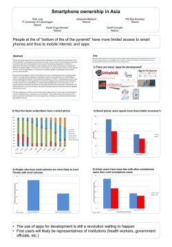
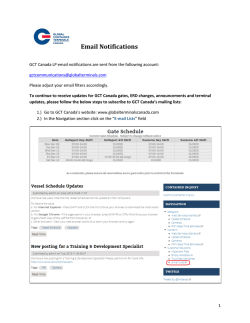
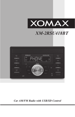
Pub. 42004-355G GAI-TRONICS® CORPORATION A HUBBELL COMPANY Retrofit ADA Compliant S.M.A.R.T. Emergency Phones TABLE OF CONTENTS Getting Started.................................................................................................................................1 Product Overview ................................................................................................................................... 1 Standard Operation ................................................................................................................................ 3 Placing an Emergency Call from a S.M.A.R.T. Phone (All Models) ...................................................................3 Placing a Non-Emergency Call (Models 298-003RT4/RT6 and 298-003CB6 Only)...........................................3 Receiving a Call....................................................................................................................................................3 Disconnecting Calls ..............................................................................................................................................3 Installation ......................................................................................................................................4 Safety Guidelines..................................................................................................................................... 4 General Installation Guidelines ............................................................................................................. 4 Tamper-Resistant Hardware .................................................................................................................................4 Conduit Installation Details ..................................................................................................................................4 Installation Procedure ............................................................................................................................ 5 Setup ................................................................................................................................................7 Hardware Configuration........................................................................................................................ 7 Auto-answer Configuration ..................................................................................................................................7 Polarity Configuration ..........................................................................................................................................7 Audio Level Adjustment......................................................................................................................... 8 Auxiliary Output..................................................................................................................................... 9 Programming......................................................................................................................................... 10 Enter the Programming Mode.............................................................................................................................10 Basic Programming Commands..........................................................................................................................11 Maintenance..................................................................................................................................14 Specifications ................................................................................................................................15 Replacement Parts.........................................................................................................................16 Confidentiality Notice ...................................................................................................................16 GAI-Tronics Corporation 400 E. Wyomissing Ave. Mohnton, PA 19540 USA 610-777-1374 800-492-1212 Fax: 610-796-5954 VISIT WWW.GAI-TRONICS.COM FOR PRODUCT LITERATURE AND MANUALS PUB. 42004-355G Retrofit ADA Compliant S.M.A.R.T. Emergency Phones Getting Started Product Overview Thank you for your purchase of a GAI-Tronics S.M.A.R.T. ADA-compliant emergency telephone. In addition to providing standard emergency telephone operation, GAI-Tronics Self-Monitoring and Reporting Telephones (S.M.A.R.T.) incorporate leading-edge technology to provide optimum performance and flexibility. For example, when interfaced to our Telephone Management Application (TMA) the health of each telephone is monitored and reported. For complete details, please refer to the on-line help included with TMA. This manual applies to the following GAI-Tronics S.M.A.R.T. ADA-Compliant Emergency Telephones designed as retrofit models for mounting in existing RT and CB-type proprietary enclosures: Model Description 297-003RT4 Flush-panel Emergency Phone – This phone has a heavy-gauge brushed stainless steel front panel that includes an emergency push button. It provides the functionality of a standard GAI-Tronics Model 297-003 Emergency Phone, but is designed to be mounted into an existing proprietary RT-type enclosure using four mounting screws. 297-003RT6 Provides the same functionality as above, but is designed to be mounted into an existing proprietary RT-type enclosure using six mounting screws. 297-003CB6 Provides the same functionality as above, but is designed to be mounted into an existing proprietary CB-type enclosure using six mounting screws. 298-003RT4 Flush-panel Emergency Phone with Keypad – This phone has a heavy-gauge brushed stainless steel front panel equipped with a 12-button keypad, an emergency push button, and a call (off-hook) button. It provides the functionality of a standard GAI-Tronics Model 298-003 Emergency Phone, but is designed to be mounted into an existing proprietary RT-type enclosure using four mounting screws. 298-003RT6 Provides the same functionality as above, but is designed to be mounted into an existing proprietary RT-type enclosures using six mounting screws. 298-003CB6 Provides the same functionality as above, but is designed to be mounted into an existing proprietary CB-type enclosures using six mounting screws. All of the above S.M.A.R.T. emergency telephones comply with the Americans with Disabilities Act (ADA). Each phone includes a Braille tag for vision-impaired individuals to identify the functions of the telephone and a visual indication for hearing-impaired individuals indicating that an emergency call has been answered. The CALL RECEIVED W HEN LIT LED is the visual call received indicator. When a call is initiated by pressing the emergency push button, the LED will initially flash. When the telephone is answered and audio is detected, the LED will light steady. The LED remains on steady until the call is disconnected. GAI-Tronics Corporation 400 E. Wyomissing Ave. Mohnton, PA 19540 USA 610-777-1374 800-492-1212 Fax: 610-796-5954 VISIT WWW.GAI-TRONICS.COM FOR PRODUCT LITERATURE AND MANUALS RETROFIT ADA-COMPLIANT S.M.A.R.T. EMERGENCY PHONES Pub. 42004-355G PAGE 2 of 17 The GAI-Tronics S.M.A.R.T. telephone product line offers a wide variety of configurable options making the phones suitable for a diverse range of applications. Most configurable options can be changed from another telephone. However, access to all configurable options is only available through TMA. The following are examples of configurable options: • Pre-programmed auto-dial telephone numbers • Call termination method (automatic or manual) • Maximum call duration • Answering options • Auxiliary input configuration These functions are initially programmed during manufacturing and testing. After installation, they can be programmed remotely via DTMF data calls, either manually or through TMA. Set the emergency auto-dial phone numbers in accordance with your security plan. For most applications, the other function settings will not need to be changed from their factory defaults. For details regarding configurable options and the factory defaults, please refer to the programming section of this manual and the on-line help available with TMA. The emergency push button can be programmed to call three unique telephone numbers. The unique telephone numbers include a primary telephone number and two backup, or roll over, numbers. In the event an emergency call cannot connect to the primary telephone number (i.e., a busy signal or no answer), the emergency phone will automatically dial the first backup, or roll over, number. Again, in the event an emergency call cannot connect to first backup telephone number, the emergency phone will automatically dial the second backup, or roll over, number. This sequence will continue either until the emergency call is answered or the programmed number of retries is reached. All of the above S.M.A.R.T. telephones are line-powered telephones and can be connected to any of the following: • Central Office (CO) line to the Public Switched Telephone Network (PSTN) • 24 V dc or 48 V dc analog station port of Private Branch Exchange (PBX), Private Automatic Branch Exchange (PABX) or KSU. Connection may not be made to pay phone extensions or shared service (party) lines. The phones require a minimum line current of 24 mA to operate. However, when available line current is below 35 mA, depending on the stability of the telephone line, the telephone’s operation can be affected. To minimize the effects of lower line current, GAI-Tronics offers a plug-in power supply, Model 40404045. Please refer to General Installation Guidelines. f:\standard ioms - current release\42004 instr. manuals\42004-355g.doc 11/09 RETROFIT ADA-COMPLIANT S.M.A.R.T. EMERGENCY PHONES Pub. 42004-355G PAGE 3 of 17 Standard Operation There are two types of telephones described in this manual. The first includes a single emergency push button and the second includes an emergency push button, a call push button, and telephone keypad. The operation of both is listed below. Placing an Emergency Call from a S.M.A.R.T. Phone (All Models) To place an emergency call: 1. Press the EMERGENCY push button to place an immediate call to a preprogrammed emergency number, typically a security office or 911. 2. As the factory default, the CALL RECEIVED W HEN LIT LED will light steady when the phone detects sound (i.e., “Hello, Security….”). 3. As an alternate operation, the emergency phone can be configured to require operator action to light the CALL RECEIVED W HEN LIT LED. If this mode is configured, the operator lifts the handset, and presses # (or *) to acknowledge the call and then the CALL RECEIVED W HEN LIT LED will light steady. Placing a Non-Emergency Call (Models 298-003RT4/RT6 and 298-003CB6 Only) To place a non-emergency call: 1. Press the CALL push button. 2. Wait for dial tone. 3. Use the keypad to dial the desired number. 4. At the end of the conversation, press the CALL push button again to put the phone on-hook. Receiving a Call When a S.M.A.R.T. emergency telephone is called, the phone will automatically go off-hook and a conversation can take place. Disconnecting Calls There are several methods included in the S.M.A.R.T. emergency telephones to disconnect calls. There are both manual and automatic disconnect methods. The disconnect methods include the following: • Remotely disconnect of an emergency call, operator enters either the # # or *99 control command. • Manually disconnect an emergency call, press the EMERGENCY button after 15 seconds (can be disabled). • Manually disconnect a non-emergency call, press the CALL button a second time. • Automatically disconnect; - All calls, loop current drop disconnect. - All calls, maximum call duration timeout (configurable from 1 minute to 4 ½ hours) - Emergency and incoming calls, call progress tones (dial tone, busy signal, fast busy (or reorder) tone) For factory defaults and available options, please refer to the Programming section of this manual. f:\standard ioms - current release\42004 instr. manuals\42004-355g.doc 11/09 RETROFIT ADA-COMPLIANT S.M.A.R.T. EMERGENCY PHONES Pub. 42004-355G PAGE 4 of 17 Installation ATTENTION Installation should be performed by qualified personnel and only in accordance with the National Electrical Code or applicable local codes. Safety Guidelines When installing any GAI-Tronics telephone equipment, please adhere to the following guidelines to ensure the safety of all personnel: • • • • • • Do not install telephone wiring during a lightning storm. All telephone models must be properly connected to earth ground to protect personnel and to minimize the effects of any electrostatic discharge (e.g., lightning). The Retrofit S.M.A.R.T. Emergency Phones each include a ground terminal. Please note proper grounding does not eliminate the need for lightning protection for the telephone or the telephone system. Install a UL Listed lightning arrestor on any phone installed where the phone or phone cable is at risk of being exposed to lightning strikes. The lightning arrestor must be installed as close to the phone as possible to maximize the protection. It must not be installed within the enclosure supplied with the phone. Please consult our Service Center at 800-492-1212 for further information. Do not install telephone jacks in wet locations unless the jack is specifically designed for wet locations. Do not touch uninsulated telephone wires or terminals unless the telephone line has been disconnected at the network interface. The Model 40404-045 Power Supply must be connected to an ac source within 4 feet of the telephone. The ac source and power supply must be mounted in a dry location, such as a GAI-Tronics stanchion. General Installation Guidelines GAI-Tronics S.M.A.R.T. phones are designed to operate on telephone lines as detailed in the Product Overview section of this manual. The telephones are designed to operate with one telephone per line. If telephones are operated in parallel or “party line configuration” you may experience sporadic phone operation, difficulties with programming, or premature disconnection of calls. Additionally, if special features, e.g. voice mail, call waiting, etc, are not disabled, the phone may not function. Tamper-Resistant Hardware All of the telephones described in this manual are vandal resistant. The front panel for each telephone covered in this manual is attached to its enclosure with tamper-resistant screws. To ease installation, every RT Series and CB Series telephone is shipped with a tamper-resistant screwdriver bit. Conduit Installation Details GAI-Tronics recommends installing telephone lines in conduit to protect against accidental damage and vandalism. To prevent moisture from entering the enclosure, we strongly recommend the following: • • • Conduit should enter the enclosure from the bottom. Sealed fittings should be installed at all cable entry points. Silicone sealant or equivalent should be applied around and inside all conduit entries. f:\standard ioms - current release\42004 instr. manuals\42004-355g.doc 11/09 Pub. 42004-355G PAGE 5 of 17 RETROFIT ADA-COMPLIANT S.M.A.R.T. EMERGENCY PHONES Installation Procedure 1. Remove the back box from the front cover. 2. Feed the telephone line through either the top or bottom cutout. Using the bottom entry is recommended. 3. Re-install the back box. 4. The telephone line is equipped with a USOC RJ11C-type modular connector. (An inline coupler is provided for use, if necessary.) Plug the connector into the mating connector inside the enclosure. 5. If configuration changes are necessary, remove the back box, and using the Setup section of this manual, • • • Make hardware configuration changes. See the Hardware Configuration section on page 7 for details. Adjust the audio levels if necessary. See the Audio Level Adjustment section on page 8 for details. Perform the initial programming. See the Programming section on page 10. 6. Verify operation by calling to and from another phone. 7. Complete the installation by attaching the front panel assembly to the rear enclosure using the tamper-resistant screws. Figure 2. Model 297-003RT4 f:\standard ioms - current release\42004 instr. manuals\42004-355g.doc 11/09 Figure 1. Typical Side View of Telephone Assembly Figure 3. Model 297-003RT6 RETROFIT ADA-COMPLIANT S.M.A.R.T. EMERGENCY PHONES Pub. 42004-355G PAGE 6 of 17 Figure 4. Model 297-003CB6 Figure 5. Model 298-003RT6 Figure 6. Model 298-003RT4 Figure 7. Model 298-003CB6 f:\standard ioms - current release\42004 instr. manuals\42004-355g.doc 11/09 RETROFIT ADA-COMPLIANT S.M.A.R.T. EMERGENCY PHONES Pub. 42004-355G PAGE 7 of 17 Setup Hardware Configuration The hardware configuration options are explained in detail in the following sections, and the necessary jumper settings are identified to enable or disable each option. We recommend reading each section, recording the selected options, making the necessary changes, and creating a record of your settings. See Figure 8 on page 8 for the jumper locations. Auto-answer Configuration Factory Setting: Auto-answer feature enabled The Auto-answer feature enables or disables the automatic answering of an incoming call, which allows TMA to monitor the health of this phone via polling. When the Auto-answer feature is enabled, the phone automatically answers the call and attempts to communicate with TMA. If the caller is not TMA, then the phone rings its sounder to alert a user to lift the handset off-hook. Enable: Insert the J14 jumper on pins 2 and 3. Disable: Insert the J14 jumper on pins 1 and 2 (Do not use this setting except under the direction of GAITronics personnel.) NOTE: The Auto-answer feature must be enabled during remote programming, and to allow the GAI-Tronics Telephone Management Application PC to contact the phone. Polarity Configuration Factory Setting: Non-polarity sensitive This telephone can be configured to be polarity or non-polarity sensitive. With the non-polarized setting, the telephone regardless of tip and ring polarity. With the polarized setting, the telephone only operates with the telephone line’s positive terminal connected to the tip. Use the Polarity Sensitive setting to allow a line voltage reversal disconnect signal to disconnect the call. Non-polarity Sensitive: Insert the J6 jumper on pins 2 and 3. Polarity Sensitive: Insert the J6 jumper on pins 1 and 2. f:\standard ioms - current release\42004 instr. manuals\42004-355g.doc 11/09 RETROFIT ADA-COMPLIANT S.M.A.R.T. EMERGENCY PHONES Pub. 42004-355G PAGE 8 of 17 Figure 8. Emergency Phone PCBA Audio Level Adjustment The speaker volume and microphone sensitivity are factory set to nominal levels that are acceptable for most installations. However, some installations may require adjustments for the speaker and microphone. Both the speaker and microphone adjustments are made using potentiometers on the emergency phone PCBA. R106 is the speaker volume adjustment, and R88 is the microphone sensitivity adjustment. Refer to Figure 7 for the potentiometer locations. After making any adjustments to the audio levels, perform the automatic line level compensation as detailed in the programming section of this manual. When the phones leave the factory, the microphone potentiometer is set near minimum, and the speaker pot is set to maximum. The speaker volume potentiometer (R106) provides 6 dB range of adjustment and the microphone sensitivity potentiometer (R88) provides 12 dB range of adjustment. f:\standard ioms - current release\42004 instr. manuals\42004-355g.doc 11/09 RETROFIT ADA-COMPLIANT S.M.A.R.T. EMERGENCY PHONES Pub. 42004-355G PAGE 9 of 17 Special care must be given to adjusting the speaker volume and microphone level. If one or both of the levels are set too high, acoustic feedback (howling) can occur. If acoustic feedback occurs, we recommend returning both potentiometers to the nominal factory settings and beginning the adjustment again from this point. Additionally, the acoustical characteristics of the emergency phones are different both when the front panel is removed from the enclosure and when the front panel is tightly mounted in the enclosure. After making any volume adjustments, we recommend mounting the front panel to the enclosure and again testing the phone. Auxiliary Output Each telephone includes one isolated solid state switch capable of switching a maximum of 48 V dc, 125 mA or 28 VRMS ac, 80RMS mA. TB2 (OUT1) on the emergency phone PCBA provides the connections for the auxiliary output. Refer to Figure 8 for the location of TB2. The auxiliary output allows peripheral equipment, such as beacons, video cameras, and alarm generators, to be activated when the EMERGENCY push button is pressed. The relay remains energized for the duration of the emergency call. In many applications, the auxiliary output is used to operate a GAI-Tronics Model 530FB/531A Beacon (sold separately). For connection details, please refer to the Model 530FB/531A installation bulletin included with the beacon. Information is also available at www.gai-tronics.com. f:\standard ioms - current release\42004 instr. manuals\42004-355g.doc 11/09 RETROFIT ADA-COMPLIANT S.M.A.R.T. EMERGENCY PHONES Pub. 42004-355G PAGE 10 of 17 Programming All S.M.A.R.T. Phone models are programmable. The phone settings are initially programmed during manufacturing and testing. Factory default settings can be found in Table R-1. The following section provides instructions for programming basic features needed to initially set up the phone from another touch-tone phone. We recommend using a handset phone exclusively when programming the S.M.A.R.T. phone remotely. If a speakerphone is used for programming, the background noise can lead to incorrect settings. A cell phone is also not recommended. TMA is required to access many of the programmable features of the emergency telephones. For programming using TMA, refer to the on-line help provided with the software, or contact the GAITronics Field Service Department. Enter the Programming Mode Read the entire programming section and carefully plan your programming before beginning the process. For each setting that will be changed, we recommend writing down the key sequence from the Command column of Table R-1, Basic Programming Commands. Having the programming information written down allows you to enter the key sequence at a steady pace. This is important because the programming sequence times out if there is a pause of more than 5 seconds during the programming sequence. Complete the following steps to enter the programming sequence from a remote DTMF telephone: 1. Call the telephone to be programmed. (Do not use a cellular phone.) 2. Listen for a confirmation tone during ringing, which signals that the telephone has answered. 3. Press *** to enter the programming mode. 4. Wait two seconds. 5. Enter **0000 (0000 is the factory default maintenance PIN #.) 6. Enter *20. If the phone has successfully entered into the maintenance mode, the phone will respond with six DTMF digits. If access to the maintenance mode is denied, the phone will respond with two DTMF digits. If access is denied, repeat steps 5 and 6 to again request access. 7. Complete the desired programming. Refer to the Basic Programming Commands section for options. 8. Listen for a confirmation tone at the end of each programming sequence, which indicates the programming change was accepted. 9. When finished programming, press *99 to exit the programming mode. f:\standard ioms - current release\42004 instr. manuals\42004-355g.doc 11/09 RETROFIT ADA-COMPLIANT S.M.A.R.T. EMERGENCY PHONES Pub. 42004-355G PAGE 11 of 17 Basic Programming Commands The following programming commands can be entered from any touch-tone telephone. Acceptance of data transfer commands is indicated via a return code transmitted as an audible DTMF tone. Auto-dial Memory When the EMERGENCY button is pressed, the S.M.A.R.T. Phone dials a pre-programmed telephone number (the primary number). If the call cannot connect (line busy, no answer), the phone will redial using the first backup (roll-over) number. If again the call cannot connect, the phone will redial using the second backup (roll-over) number. This sequence will continue until either the emergency call is answered, or the programmed number of retries is reached. Use the *1 command to program these three auto-dial numbers. The three auto-dial telephone numbers are labeled as 11 (primary), 12 (first roll-over), and 13 (second roll-over). You can program these for three different numbers, or set them to the same telephone number. Each auto-dial memory storage location accommodates up to 24 characters. To enter the auto-dial number into memory storage, or to change the number in storage, enter *11<N><CHAR># *1 Data transfer command 1<N> Auto-dial memory location (N = 1, 2, or 3) <CHAR> Telephone number to be stored in memory location (up to 24). Valid entries are 0-9 and the following 2-digit codes: *1 provides a 0.6-second pause in the dialing sequence, *2 provides a DTMF #, and ** provides a DTMF *. # End-of-string indicator The command *1115551212#, for example, sets the primary number to 555-1212. After each auto-dial memory storage location is successfully programmed, the phone returns a systemgenerated DTMF check-digit. If the phone is installed on a ring down telephone line, clear the first auto-dial memory using the command *111#. f:\standard ioms - current release\42004 instr. manuals\42004-355g.doc 11/09 RETROFIT ADA-COMPLIANT S.M.A.R.T. EMERGENCY PHONES Pub. 42004-355G PAGE 12 of 17 Automatic Line Level Compensation for Optimum Audio Performance Every telephone line has different audio and electrical characteristics. To accommodate the varying lines, the telephone has an automatic line level compensation function. When a telephone is first installed and connected to a telephone line, we recommend initiating the automatic level compensation feature. The automatic line level compensation is initiated in the programming mode with the *78 command, as follows: *787 Data transfer command # End-of-string indicator After the *78 command is successfully entered, the phone returns a system-generated DTMF check-digit. To complete the automatic line level compensation, when programming is completed and the phone placed back on-hook, the following process must be followed: For single button emergency phones: 1. Remove the phone from the back box or enclosure. 2. Disconnect the emergency push button from J7, the “Emerg PB” socket on the phone PCBA. 3. Connect the emergency push button to J1, the “Call PB” socket on the phone PCBA. Press the emergency push button. When dial tone is steady (with no volume variations), the process is complete. Depending on the phone line and the duration dial tone, it may be necessary to repeat this step one or more times. 4. Disconnect the emergency push button from J1, the “Call PB” socket on the phone PCBA. 5. Reconnect the emergency push button to J7, the “Emerg PB” socket on the phone PCBA. 6. Install the phone in the back box or enclosure. For emergency phones with a call push button and keypad: Press the call push button. When dial tone is steady (with no volume variations), the process is complete. Depending on the phone line and the duration dial tone, it may be necessary to repeat this step one or more times. f:\standard ioms - current release\42004 instr. manuals\42004-355g.doc 11/09 RETROFIT ADA-COMPLIANT S.M.A.R.T. EMERGENCY PHONES Pub. 42004-355G PAGE 13 of 17 Call Time-out The call time-out feature is used to limit the maximum duration of a call. The call time-out can be any duration between one minute and 4 ½ hours. The duration is set in ½ second increments and the valid range is from 120 to 32,400. To determine the value associated with a specific time duration, see the example below. *37 Data transfer command <120~32400> Call duration (120 to 32400 ½ seconds) – See example below. # End of string indicator Example: To determine what to enter for the call time-out duration, multiply the desired time limit, in minutes, by 120. For example, to determine the call duration entry for a call time-out of five (5) minutes, do the following: 5 minutes × 120 = 600 To enter a call time-out duration of five (5) minutes, enter the character string *37600#. When the call time-out duration has been successfully entered, the phone returns a system-generated DTMF check-digit. Table R-1. Basic Programming Commands Command: Factory Default: Description: *1NN <CHARAC># N/A Write Memory NN (11-13) with characters (up to 24) *787# 7 Initiate automatic level compensation *37<120~32400># 840 Write Call Time-out (120-32400 × ½ sec). Factory default is 840, or 7 minutes. *821 N/A Turn on the relay output (OUT1) *921 N/A Turn off the relay output (OUT1) *99 N/A End programming call. The S.M.A.R.T. phone hangs up. f:\standard ioms - current release\42004 instr. manuals\42004-355g.doc 11/09 RETROFIT ADA-COMPLIANT S.M.A.R.T. EMERGENCY PHONES Pub. 42004-355G PAGE 14 of 17 Maintenance TMA users can schedule auto-dial maintenance calls to alert maintenance personnel of any unusual sensor or fault conditions that exist. S.M.A.R.T. Phones can also be programmed to generate an auto-dial maintenance call when certain sensor events are discovered. Access to the S.M.A.R.T. Phone’s maintenance mode is restricted through the use of the maintenance access PIN. The maintenance access PIN should be distributed only to trained maintenance personnel. If your S.M.A.R.T. Phone requires service, contact your GAI-Tronics Regional Service Center for a return authorization number (RA#). Equipment should be shipped prepaid to GAI-Tronics with a return authorization number and a purchase order number. If the equipment is under warranty, repairs will be made without charge. Please include a written explanation of all defects to assist our technicians in their troubleshooting efforts. Call 800-492-1212 inside the USA or 610-777-1374 outside the USA for help identifying the Regional Service Center closest to you. f:\standard ioms - current release\42004 instr. manuals\42004-355g.doc 11/09 RETROFIT ADA-COMPLIANT S.M.A.R.T. EMERGENCY PHONES Pub. 42004-355G PAGE 15 of 17 Specifications TMA Compatibility profile type ...................................................................... GTC S.M.A.R.T. Hands-free Auto-dial digit limit ......................................................................................................................... 24 digits Electrical Audio output .......................................................... Voice - 80 dB SPL @ 1 meter with 40 mA loop current 1 kHz tone - 76 dB SPL @ 1 meter with 40 mA loop current Input ......................................................................................................................................... 24 or 48 V dc Phone line requirements........................................................................... Loop start, central office (CO), or Analog station port (PBX, PABX, or KSU) Minimum loop start....................................................................................... 24 mA (35 mA recommended) Auxiliary output (isolated solid state switch) ................................................................. 48 V dc @ 125 mA 28 VRMS @ 80 mARMS Signaling ......................................................................................................................... DTMF 100 ms tone Memory..................................................................................................................... Non-volatile EEPROM Mechanical Operating temperature range................................................................................................ -40º C to +60º C Relative humidity.............................................................................................. Up to 95%, no condensation Panel construction...................................................................................... 14-gauge, brushed stainless steel Panel dimensions – overall RT models....... 11.88 H × 8.25 W × 2.80 D inches (301.6 × 209.6 × 71.1 mm) Panel dimensions – overall CB models....... 11.75 H × 8.50 W × 2.80 D inches (298.4 × 215.9 × 71.1 mm) Hole pattern for RT 4-screw models..................................... 6.00 W × 11.63 H inches (154.4 × 295.4 mm) Hole pattern for RT 6-screw models...............7.31 W × 9.96 H (w/ center screw) inches (185.7 × 253 mm) Hole pattern for CB 6-screw models..........7.75 W × 10.26 H (w/ center screw) inches (196.8 × 260.4 mm) Back box ............................................................. 16-gauge cold-rolled steel with black polyurethane finish Weight........................................................................................................................ Approximately 6.5 lbs. Approvals Safety of Information Technology Equipment ...................................................................... UL/CSA 60950 Enclosures for Electrical Equipment..................................................................................... UL 50, Type 3R 47 CFR Part 68 Certification Number .......................................................................................... US: ADGTE04B0414HAC Ringer Equivalence Number.................................................................................................................... .4B Network connection (USOC).................................................................................................................. RJ11 IC Information (Canada) IC Certification Number ........................................................................................... 882B-GTC S.M.A.R.T. Ringer Equivalence Number.................................................................................................................... .4B Connection Method.............................................................................................................................CA11A f:\standard ioms - current release\42004 instr. manuals\42004-355g.doc 11/09 Pub. 42004-355G PAGE 16 of 17 RETROFIT ADA-COMPLIANT S.M.A.R.T. EMERGENCY PHONES Replacement Parts 297003RT4 297003RT6 Part No. Description 54001-003 Tamperproof Torx bit (T25) 54001-005 Tamperproof Torx bit (T15) 12562-103 PCBA Replacement Kit (S.M.A.R.T. Hands-free) 51035-005 PCBA, Keypad SC2691 Tamperproof Screws 8-32 28299-008 Tamperproof Screws 10-24×1-inch 12520-006 Push Button Replacement Kit (1.5-inch, Red) 12520-007 Push Button Replacement Kit (1.0-inch, Black) 13507-005 Microphone Replacement Kit 12522-005 Piezo Speaker Replacement Kit – 297/298 297003CB6 298003RT4 298003RT6 298003CB6 Confidentiality Notice This manual is provided solely as an operational, installation, and maintenance guide and contains sensitive business and technical information that is confidential and proprietary to GAI-Tronics. GAITronics retains all intellectual property and other rights in or to the information contained herein, and such information may only be used in connection with the operation of your GAI-Tronics product or system. This manual may not be disclosed in any form, in whole or in part, directly or indirectly, to any third party. f:\standard ioms - current release\42004 instr. manuals\42004-355g.doc 11/09 RETROFIT ADA-COMPLIANT S.M.A.R.T. EMERGENCY PHONES Pub. 42004-355G PAGE 17 of 17 User Instructions (USA) This equipment complies with Part 68 of the FCC rules and the requirements adopted by the ACTA. On this equipment is a label that contains, among other information, a product identifier in the format US:AAAEQ##TXXXX. If requested, this number must be provided to the telephone company. User Instructions (Canada) CP-01, Issue 8, Part I: Section 14.1 NOTICE: The Industry Canada label identifies certified equipment. This certification means that the equipment meets certain telecommunications network protective, operational and safety requirements as prescribed in the appropriate Terminal Equipment Technical Requirements document (s). The Department does not guarantee the equipment will operate to the user's satisfaction. Before installing this equipment, users should ensure that it is permissible to be connected to the facilities of the local telecommunications company. The equipment must also be installed using an acceptable method of connection. The customer should be aware that compliance with the above conditions may not prevent degradation of service in some situations. Repairs to certified equipment should be coordinated by a representative designated by the supplier. Any repairs or alterations made by the user to this equipment, or equipment malfunctions, may give the telecommunications company cause to request the user to disconnect the equipment. Users should ensure for their own protection that the electrical ground connections of the power utility, telephone lines and internal metallic water pipe system, if present, are connected together. This precaution may be particularly important in rural areas. CP-01, Issue 8, Part I: Section 14.2 NOTICE: The Ringer Equivalence Number (REN) assigned to each terminal device provides an indication of the maximum number of terminals allowed to be connected to a telephone interface. The termination on an interface may consist of any combination of devices subject only to the requirement that the sum of the Ringer Equivalence Numbers of all the devices does not exceed 5. f:\standard ioms - current release\42004 instr. manuals\42004-355g.doc 11/09 Warranty Equipment. GAI-Tronics warrants for a period of one (1) year from the date of shipment, that any GAI-Tronics equipment supplied hereunder shall be free of defects in material and workmanship, shall comply with the then-current product specifications and product literature, and if applicable, shall be fit for the purpose specified in the agreed-upon quotation or proposal document. If (a) Seller’s goods prove to be defective in workmanship and/or material under normal and proper usage, or unfit for the purpose specified and agreed upon, and (b) Buyer’s claim is made within the warranty period set forth above, Buyer may return such goods to GAI-Tronics’ nearest depot repair facility, freight prepaid, at which time they will be repaired or replaced, at Seller’s option, without charge to Buyer. Repair or replacement shall be Buyer’s sole and exclusive remedy. The warranty period on any repaired or replacement equipment shall be the greater of the ninety (90) day repair warranty or one (1) year from the date the original equipment was shipped. In no event shall GAI-Tronics warranty obligations with respect to equipment exceed 100% of the total cost of the equipment supplied hereunder. Buyer may also be entitled to the manufacturer’s warranty on any third-party goods supplied by GAI-Tronics hereunder. The applicability of any such third-party warranty will be determined by GAI-Tronics. Services. Any services GAI-Tronics provides hereunder, whether directly or through subcontractors, shall be performed in accordance with the standard of care with which such services are normally provided in the industry. If the services fail to meet the applicable industry standard, GAI-Tronics will re-perform such services at no cost to buyer to correct said deficiency to Company's satisfaction provided any and all issues are identified prior to the demobilization of the Contractor’s personnel from the work site. Re-performance of services shall be Buyer’s sole and exclusive remedy, and in no event shall GAITronics warranty obligations with respect to services exceed 100% of the total cost of the services provided hereunder. Warranty Periods. Every claim by Buyer alleging a defect in the goods and/or services provided hereunder shall be deemed waived unless such claim is made in writing within the applicable warranty periods as set forth above. Provided, however, that if the defect complained of is latent and not discoverable within the above warranty periods, every claim arising on account of such latent defect shall be deemed waived unless it is made in writing within a reasonable time after such latent defect is or should have been discovered by Buyer. Limitations / Exclusions. The warranties herein shall not apply to, and GAI-Tronics shall not be responsible for, any damage to the goods or failure of the services supplied hereunder, to the extent caused by Buyer’s neglect, failure to follow operational and maintenance procedures provided with the equipment, or the use of technicians not specifically authorized by GAI-Tronics to maintain or service the equipment. THE WARRANTIES AND REMEDIES CONTAINED HEREIN ARE IN LIEU OF AND EXCLUDE ALL OTHER WARRANTIES AND REMEDIES, WHETHER EXPRESS OR IMPLIED BY OPERATION OF LAW OR OTHERWISE, INCLUDING ANY WARRANTIES OF MERCHANTABILITY OR FITNESS FOR A PARTICULAR PURPOSE. Return Policy If the equipment requires service, contact your Regional Service Center for a return authorization number (RA#). Equipment should be shipped prepaid to GAI-Tronics with a return authorization number and a purchase order number. If the equipment is under warranty, repairs or a replacement will be made in accordance with the warranty policy set forth above. Please include a written explanation of all defects to assist our technicians in their troubleshooting efforts. Call 800-492-1212 (inside the USA) or 610-777-1374 (outside the USA) for help identifying the Regional Service Center closest to you. (Rev. 10/06)


© Copyright 2026