
LYN400X-3120 - LiftMaster
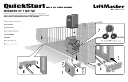
SISTEMA OPERADOR PARA REJAS ABATIBLES
LYN400X-3120
The Chamberlain Group, Inc.
845 Larch Avenue
Elmhurst, IL 60126
(630) 516-8423
This safety alert symbol means “Caution” - failure to comply with such an instruction involves risk of personal injury or
damage to property. Please read these warnings carefully.
This gate drive mechanism is designed and tested to offer appropriately safe service provided it is installed and operated
in strict accordance with the following safety rules.
Incorrect installation and/or failure to comply with the following instructions may result in serious personal injury or
property damage.
It is important to make sure that the gate always
runs smoothly. Gates which stick or jam must be
repaired immediately. Employ a qualified technician
to repair the gate, never attempt to repair it yourself.
When using tools and small parts to install or carry out
repair work on a gate exercise caution and do not wear
rings, watches or loose clothing.
Installation and wiring must be in compliance with your
local building and electrical installation codes. Power
cables must only be connected to a properly earthed
supply.
Keep additional accessories away from children. Do not
allow children to play with pushbuttons or remote
controls. A gate can cause serious injuries as it closes.
Disconnect electric power to the system before
making repairs or removing covers.
A disconnecting device must be provided in the
permanently-wired installation to guarantee allpole
disconnection by means of a switch (at least 3mm
contact gap) or by a separate fuse.
Any entrapment possibility by the moving wing
between wing & walls must be secured with
safety edges or IR-sensors.
Please remove any locks fitted to the gate in order to
prevent damage to the gate.
Make sure that people who install, maintain or
operate the gate drive follow these instructions.
Keep these instructions in a safe place so that you can
refer to them quickly when you need to.
After the installation a final test of the full function of
the system and the full function of the safety devices
must be done.
This drive cannot be used with a gate incorporating a
wicket door unless the drive cannot be operated with
the wicket door open.
Contents: General advice on
installation and use:
Contents list: page 1
Content of the carton: page 1, figure 1
Before you begin: page 2
Checklist: page 2
Gate types/installation height:
page 2, figure 2 A-F
Gate configuration:
page 2, figure 3 A-F
Gate stops: page 2, figure 4
Post bracket/Gate fixing bracket:
pages 2-3, figures 5 A-E
The full protection against potential squeeze
or entrapment must work direct when the
drive arms are installed.
Release of drive arms:
page 3, figure 6
Installing the drive arms:
page 3, figure 7 A-B
Wiring: page 3
Initial operation: page 3
Maintenance work: page 3
Technical Data: page 3
Electronic control with connections:
page 4, figure 8
Electrical Installation:
page 4, figure 9 - 11
Force adjustment: page 5
Safety: page 5, figures 12 A+B
Combined Operation: page 5
Antenna: page 5, figure 13 -A+B
Flashing Lamp: Page 5, figure 8
Key switch: page 5, figure 8
Initial setting of Remote control:
page 6, figure 14
Initial Operation: page 6
Replacement Parts: figure 15
CONTENT OF THE CARTON 1
(1)
(2)
(3)
(4)
(5)
(6)
Motor (1)
Electronic Control (1)
Postbracket (1)
Keys (2)
Gate fixing bracket (1)
Capacitor (1)
(7) Manual (1)
(8) Clevis pin (2) and Rings (4)
(9) 3-Channel Remote Control Mini 315Mhz (2)
(10) IR Sensor (1 pair) (optional)
(11) Flashing lamp (1) (optional)
(12) Antenna (1) (optional)
1-GB
PLEASE START BY READING THESE IMPORTANT SAFETY RULES • SAVE THESE INSTRUCTIONS
GATE CONFIGURATION 3
How far must the gate leaf open?
90 degrees or up to 115 degrees. An opening angle in excess of 115
degrees is possible to a limited extent but is not recommended.
Reason: the drive mechanism always runs at the same speed. The
further the gate has to be opened, the faster the gate leaf must travel.
Movement becomes more erratic and this subjects the fittings and
gate to extreme stresses. Non-identical opening angles cause one
drive mechanism to reach its destination first, but continues to run,
thereby forcing the gate up against the gate stop until the other motor
eventually reaches its end position
(see Figures 3, A-F).
Tip for professionals: The time taken to reach the limit stop can be
controlled by deliberately selecting different A and B dimensions (left
+ right). However, this method of installing subjects the fittings to high
stresses and can cause the gate to run erratically. It is recommended
that only experienced gate installers adopt this method.
GATE STOPS 4
A SWING GATE NEEDS A FIXED GATE STOP IN BOTH THE
OPEN AND CLOSE DIRECTIONS. Gate stops save wear and tear on
the drive mechanism, gate and fittings. Operating a gate without fixed
limit stops results in poor performance. It is often dangerous, leads to
premature wear and voids your warranty!
POST FIXING BRACKET 5
INSTALLATION CHECKLIST - PREPARATIONS
Check the carton contents and read the instructions carefully. Make
sure your gate equipment operates perfectly. The gate must run
evenly and smoothly and must not stick at any point. Remember that
the ground level may be several centimeters higher in winter. The
gate must be stable and as free of backlash as possible in order to
prevent any unwanted to and fro movement. The more smoothly the
gate leaf runs, the more sensitive the force adjustment must be.
Note down any materials you still need and obtain them before
starting to install. Heavy-duty plugs, bolts, gate stops, cables,
distribution boxes, tools, etc.
GATE TYPES 2
The gate type determines the location where the drive mechanism is
installed. If the gate stop is on the ground, the drive mechanism must
also be installed at a height that is as low as possible so that it cannot
twist the gate. Use only parts of the gate frame for fixing purposes.
TYPE A, B, C
For steel gates, the gate fitting must be attached to the main frame. If
you are uncertain whether the available support is sufficiently stable,
reinforce it.
TYPE D, E, F
In the case of wooden gates, the gate fitting must be through
bolted. It is advisable to fit a plate from the outside so that the fixing
brackets cannot become loose over time. Thin wooden gates must
also be reinforced in order to withstand the stresses encountered
(e.g. type F).
Choosing the correct location for the post fixing bracket has a
decisive impact on the subsequent functioning of the system. It
determines the distance between the motor’s centre of motion and the
gate’s centre of motion and hence the opening angle. These
dimensions are referred to as dimension A and dimension B. Do
not underestimate the effect that these dimensions have on correct
functioning and running. Try and achieve the best dimension for your
opening angle, as precisely as possible and suitable for all
circumstances. See Table (Figure 3F) for dimensions A/B.
If the post is not wide enough, an extension piece must be fitted to it
(Figure 5B). If the post is too thick, cut out part of it to make it thinner
(Figure 5D) or offset the gate (Figure 5C).
To obtain ideal dimensions, it may be necessary to shorten or
lengthen the supplied hinge plate. In the case of gates that are to be
custom made, if the gate hinges are fitted on the posts appropriately,
it is possible to influence dimensions A and B. Before the final
mounting dimensions are determined, you should always check
whether or not there is any possibility that the corner of the drive
mechanism will hit the post as the gate swings.
INSTALLATION: The drive mechanism exerts considerable force
against the post. Usually, acceptable mounting dimensions are
obtained if the supplied hinge plate is welded directly onto the post. In
the case of thick stone or concrete posts, the hinge must be welded
to a base plate and attached so that the plugs cannot work loose
during operation. Heavy-duty plugs where a threaded rod is bonded
into the masonry stress-free are more suitable for this purpose than
steel or plastic straddling plugs. In the case of brickwork pillars, bolt
on a relatively large steel plate that covers several bricks and then
weld the hinge plate to it. An angle plate attached over the corner of
the post is also a good means of fixing the operators.
2-GB
BEFORE YOU BEGIN
The drive mechanism needs room to the side permitting correct
installation of drive arms. Please make sure that this is available.
Gates affected by high wind loads must also be protected by an
(electric) lock.
There are many factors to consider when choosing the right drive
mechanism. Assuming that a gate functions properly, “startup” is the
most difficult phase, once the gate is in motion, significantly less force
is usually required to move it.
• Gate size: Gate size is a very important factor. Wind can brake or
distort the gate, thereby increasing the amount of force needed to
move it considerably.
• Gate weight: The weight of the gate is not as relevant as the size.
• Effect of temperature: Low outdoor temperatures can make initial
startup more difficult (changes in the ground, etc.) or even prevent
it. High outdoor temperatures along with frequent use can trigger
thermal protection prematurely (approx. 135 ºC).
• Operating frequency/operating time: Drive mechanisms are
designed for a maximum operating time (running time) of
approximately 30% (e.g. 30% during any one hour).
IMPORTANT: The drive mechanism is not designed to operate
continuously at its maximum operating time (nonstop operation).
Otherwise the drive mechanism becomes too hot and switches off
until it cools down to the switch-on temperature. The outdoor
temperature and the gate are important parameters that affect the
actual operating time.
For steel gates, fixings should be welded on or through bolted. When
through bolting the gate, use large washers or a plate on the other
side. The drive mechanism exerts an extremely high force on this
joint.
Fixings must be through bolted for wooden gates. Wood deflects
under load and the bolt will become loose. Due to movement caused
by repeated loading, the wood deflects more and more until the gate
no longer closes correctly and has to be repaired.
Fit a reinforcing plate from the outside and one on the inside so that
the wood cannot deflect and the joint cannot become loose.
Thin wooden gates without a metal frame must also be reinforced in
order to withstand continuous stresses (e.g. type F).
Tip for professionals: The drive mechanism can also be used for light
“rising” gates or light gates with hinge bands offset up to 8º (gate
weighing 100 kg). This subjects all fittings to extreme stresses and
can cause the gate to run erratical. Special attention must be paid to
safety, especially in the case of rising gates. It is recommended that
only experienced gate installers adopt this method.
RELEASE 6
The drive mechanism can be released. The gate can then be opened
and operated manually (power failure). With a new drive mechanism,
the release action may sometimes feel stiff/jerky. This is normal and
has no effect on function.
Release: Insert the key in the cylinder lock and turn it 180 degrees.
Then turn the release lever 180 degrees – done!
Engage: Turn the lever clockwise. As soon as the gate moves or the
drive runs, the gear locks again. Use the lock to protect the lever
against unauthorized release.
INSTALLING THE DRIVE ARMS 7
Release the drive. Push the released drive onto the fittings and
secure it by using the supplied bolts and rings (Figure 7).
WIRING
The 4-pole connecting cable is approx. 80 cm long and is laid in a
curve to the controller or a watertight distribution box located above
ground. An approved cable is permanently installed from the
distribution box onwards. The capacitor can be connected inside the
distribution box or in the controller.
Connection: Connect the capacitor across terminals L1 and L1. L1
and N produce rotation direction A. The other L1 terminal and terminal
N produce reversed direction of rotation. Always remember to earth
the installation.
INITIAL OPERATION
With the gate released, manually check that the gate functions
properly. Electrical commissioning cannot be performed without a
suitable controller which you can obtain as an accessory item.
Always make sure that the mechanical and electrical safety
regulations that apply to the installation are met.
If the force on the leading edge of the gates is greater than
400N then external entrapment protection devices must be
installed. Install entrapment protection device per
manufacturer’s instructions. Devisions must meet requirements
of EN60335-2-103.
MAINTENANCE WORK
The drive mechanism is maintenance free. Check that the gate fittings
and the drive mechanism are securely fixed at regular intervals
(monthly). Release the drive and check that the gate functions
properly. Unless the gate runs smoothly it will not operate correctly
with the drive mechanism. The drive cannot eliminate the problems
caused by a gate that does not work satisfactorily.
TECHNICAL DATA
Mains supply (Motor)
120 Volt˜/ 50-60Hz
Current consumption
2,4A
Power consumption
280W
Capacitor
25μF
Max. gate width
2,5m LYN300
4,0m LYN400
Max. gate weight
200kg
Protection Class
I - IP 44
Connecting cable
H07RN-F / 80cm
Rated Thrust
250N
Travel Speed
20mm/s LYN300
12mm/s LYN400
Rated operating time
4 Minutes
Temperature
-20°C to + 55°C
3-GB
GATE FITTING 5
The gate fitting must be installed so that it is horizontal relative to the
post bracket. The distance between the gate bracket and post bracket
is referred to as the “arm span”. When the gate is closed, the drive
mechanism is 95% extended. When the gate is opened, the drive
mechanism is 5% extended. Fully retracting or extending the plunger/
spindle in operation (with gate) damages the drive mechanism and
voids the warranty. It is absolutely imperative to comply with the
required arm span under all circumstances! See Figure 5A for
dimensions.
Overview of connections
Motors: Connect the control unit exactly in accordance with the
overview of connections. The gate wing which opens first must be
motor 1 (M1) and when it first moves it must OPEN the gate. If it
closes the gate, swap terminal 5 with terminal 6 or, in the case of
motor 2 (M2), swap terminal 10 with terminal 11.
The supplied capacitor must be installed between cables 5 and 6 and
10 and 11 (the capacitor cannot be installed in a distribution box
because there is not enough room). Make sure that its terminals are
properly connected and there is a good electrical connection. The
capacitor determines the force which the motor subsequently
develops.
OVERVIEW 8
Materials required (details vary depending on particular
application).
• Distribution box
• Buried cable, at least 1.5 mm2
• Buried cable, at least 0.5 mm2
• Screws
• Wall plugs
ELECTRICAL INSTALLATION 9 - 11
Installing the electronic control unit: The electronic control unit
supplied is required for operation of the wing gate actuator. This
control unit comprises an electronic microprocessor-control system
employing the latest technology. It may be used for the connection of
1 or 2 motors and offers all connection possibilities and functions
necessary for safe and reliable operation. The electrical connections
for single- or double gates are given in Illustration 9.
The control box containing the motor control module is to be fitted
with cable entry at bottom (Illustration 10). It should not be
continuously exposed to direct sunlight. For weather protection, we
recommend the fitting of a small protection roof. Thanks to the
electronic control unit, fine adjustment of the push-pull torque is
possible. When correctly adjusted, gate movement can be easily
blocked by hand.
For the OPEN and CLOSED positions, the gate requires a stable
end stop as the swing gate actuator unit is not fitted with limit
switches and the electronic controls are switched off by time.
Current distribution: The cable which leads from the drive arm must
be laid in a standard watertight distribution box. A permanently
installed cable can be laid from the distribution box to the control unit.
It is often possible to wire the drive which is fixed besides the control
unit directly to the box. Never install distribution boxes underground.
Generally speaking, the following minimum cable crosssectional
areas must be adhered to:
100-230Volt
1,5mm2 or more
0-24Volt
0,5mm2 or more
Tips: Bell wire is often problematic in practical use because it loses
too much voltage if long lengths of wire are used. Segregate the
cables in cable trunking, i.e. motor cable and light barrier cable,
especially in the case of key-operated switches and ON switches
(from the house wiring system) to prevent interference where long
lengths of cable are used.
Description
Terminal 1
Terminal 2
Terminal 3
Terminal 4
Terminal 5
Terminal 6
Terminal 7
Terminal 8
Terminal 9
Connection
L1 - 110 V (black)
PE (green)
N (white)
Motor connection
First Motor (M1):
N (white)
M1 Direction OPEN (black-red)
(+ Capacitor)
M1 Direction CLOSED (red-black)
(+ Capacitor)
Flashing light connection:
N
L1 (120V)
Second Motor (M2):
M2 Direction CLOSED (red-black)
(+ Capacitor)
Terminal 10
M2 Direction OPEN (black-red)
(+ Capacitor)
Terminal 11
N (white)
Infrared light detector
Photocell (NC) active during closing
COM
Photocell (NC) active during opening
(without IR Sensor - Bridge between 12, 13
and 14!)
Terminal 12
Terminal 13
Terminal 14
Terminal 15
Terminal 16
Terminal 17
Terminal 15
Terminal 18
Terminal 19
Terminal 20
Terminal 21
Terminal 22
Description of connections
EMERGENCY STOP-FUNCTION
COM
Stop (NC) or bridge between 15 and 16
Control circuit connections:
Push button (NO) Motor 1 (Pedestrian-Function)
COM
Push button (NO) Motor 1 + 2
Electric lock connections:
Supply voltage 12 V AC
Supply voltage 12 V AC
Auxiliary equipment connections & IR Sensor:
Supply voltage 24 V AC (500 mA max.)
Supply voltage 24 V AC
DESCRIPTION OF JUMPERS
JP1: MOTOR SELECTION JUMPER
OPEN: (No Jumper): Use only for single wing gates
(Motor 1 operation only).
CLOSED: (With Jumper): Use for double wing gates
(Motor 1 and 2 operation).
4-GB
ELECTRONIC CONTROL 8
The control unit should be connected up last, i.e. after the motor has
been mounted, the necessary cables laid and the Infrared Sensors or
contact strips fixed in place.
In the case of permanent mounting, means of separating the system
from the mains must be provided. The contact spacing of the main
switch used in this connection must be at least 3 mm.
NOTE: In these instructions, relay contacts are designated as NC
(normally closed) and NO (normally open).
• NC contacts are closed, and open when actuated.
• NO contacts are open, and close when actuated.
Humidity and water will destroy the control unit. Always make sure
that water, humidity and condensation cannot enter the control unit. It
is vitally important that all openings and cable glands are sealed so
that they are watertight.
ANTENNA 13 A+B (OPTIONAL)
A flashing light is supplied for safety reasons and warns people in the
vicinity of the gate that it is moving. The flashing light is attached by
means of screws and wall plugs. The earth cable must be installed to
the light. Mounting is normally at the highest point (gate post). Cable
cross-section: 0.75mm2, 3-pole. Voltage: 230Volt /AC.
An external aerial is not essential. A short aerial is attached to the
radio adapter on the controller. If the range of the remote controller
has to be increased, you should fit an external aerial suitable for
315MHz (model ANT4X-1LM incl. 75 Ohm coaxial cable). Connection
is made via the radio adapter to the controller (see controller
instructions). The best place for an aerial is high up and as far as
possible from any electrical devices. The short cable aerial, which is
supplied with and fitted to the unit, must not then be used.
SAFETY • IR SENSOR 12 A+B (OPTIONAL)
The IR Sensor is provided to protect the gate. The mounting position
depends on the construction of the gate. Normally the IR Sensor
should be mounted approximately at knee height, i.e. about 35 cm
from the floor. The IR Sensors consist of a transmitter and receiver
section and must be located opposite one another. The (plastic) IR
Sensor housings can be opened with a screwdriver. The IR Sensor is
attached to the wall with small screws and wall plugs. The very
minimum requirement is one single IR Sensor, but we recommend the
use of a second IR Sensor (and if necessary even more means of
protection). It is possible to connect the light barrier as described
below.
Active when “OPENING” (terminal 14) or active when “closing”
(terminal 12). The instructions describe how to connect a single light
barrier and therefore uses both fuse inputs, i.e. active in both
directions. DIP switch 4 on the control unit controls the door wing’s
response if the light beam is interrupted while the gate is closing. An
active light barrier (only) stops the gate or an active light barrier
reverses the direction of the gate. The transmitting section requires a
2-pole cable and the receiver section a 4-pole cable. Cable crosssection: 0.5mm2 or greater. Voltage: 12/24Volt AC/DC (22/23).
DESCRIPTION OF DIP SWITCHES
The DIP switches control the general functions of the
installation:
• Automatic closing or default
• Dead man’s operation
• Electric lock function
• Response of light barrier
DIP switch 1
DIP switch 2
DIP switch 3
DIP switch 4
ON
Automatic closing
OFF
Default
ON
Dead man’s operation
OFF
Default
ON
Electric lock function
OFF
Default
ON
Light barrier (for closing) stops
the gate
OFF
Default light barrier (for closing)
opens the gate
HOLD TO RUN
Emergency stop: If a switch is connected, it can be used to stop or
disable the installation. This immediately interrupts movement of the
wing. Depending on the level of safety needed, the contact can also
be connected on the gate to the light barrier’s contacts. This
immediately stops any wing movement. In the dead man’s-mode of
operation, a gate can be used without safety devices if the operator
has a full overview of the system’s operation. Three dip switches are
situated in the top part of the control unit. Set dip switch 3 to ON. The
control unit then only functions while continuous control signals are
given by means of a transmitter, key or pushbutton. If the control
signals are interrupted, the gate stops and will move in the opposite
direction when the next signal is received.
Control lines: It is possible to open only one gate or both gates. This
function is also possible when using the radio remote control. See
initial setting of remote control. The test button on the control unit
always switches on both motors. With overlapping wings the wing
delay must be set. Wings which do not overlap must not close
simultaneously - pinch risk. See description of Potentiometer.
KEYSWITCH INSTALLATION 8
• Disconnect screw for the cover.
• Disconnect both housing screws (Surface mount only).
• Pin on key and turn completely to one side.
• Keep key turned and pull.
Connection of the cables according wiring diagram.
Assembly in reversed order.
ELECTRIC LOCK
In order to permit the use of various electro-lock systems, contact
9-10 is designed for potential free closure. The contact is closed 1
second before the motor starts up, and stays in this condition for
about 3 seconds. In other words, the lock is unlocked before the door
opens and remains actuated for 3 seconds to ensure that it does not
get locked again. This function is also operative during closure of the
gate. See also DIP switch settings.
DESCRIPTION OF POTENTIOMETER
• Force M1 Force M2:
The rotary potentiometer is used to make fine gate adjustments.
Adjust the force with which the door operates for each wing
separately.
If the force exerted by the moving wing at the closing edge
exceeds 400 N, additional safety devices (light barriers,
contact strips) must be installed. Safety device must meet the
applicable standards (Europe: EN60335-2). See also Safety
Rules.
• PAUSE
This function is only active if DIP switch 1 is set to ON. It adjusts
the time for which the gate is kept open before it closes again.
Adjustable: 8-200 s.
• OPEN-CLOSED
Adjust the maximum running time of the wing. Set the running time
to approx. 30% and then test. Correct adjustment is obtained when
the drive continues to run (hum) against the end stop for 3-5 s
each time in one complete cycle. This is necessary because the
required running time is affected by external influences and it must
be ensured that the end position is reliably reached (wind,
temperature, changes in ground). This is why end stops in the
OPEN and CLOSE direction are stipulated as mandatory.
Adjustable: 7-60 s
• WING DELAY
Controls the wing delay in the case of overlapping wings. Wing M1
opened first and closes last. A delay must always be set in order to
make sure that no one can be jammed between two closing wings.
Adjustable: 0-35 s
5-GB
SAFETY • FLASHING LAMP 8 (OPTIONAL)
LED 1
red
Monitors the light barrier for door closing.
LED ON = OK
DELETION OF PROGRAMMED
REMOTE-CONTROL CODES
Press the corresponding learn button (1 or 2) approx. 10 sec. on the
receiver PCB until the learn LED goes off. The code memorized with
this learn button has now been deleted.
LED 2
red
Monitors the light barrier for door opening
LED ON = OK
LED 3
yellow
Monitors the emergency stop contact ON=OK
REPROGRAMMING
LED 4
green
Indicates signals from key-operated switches,
pushbuttons or radio. Single-wing gate
opening function ON = signal present.
LED 5
green
Indicates signals from key-operated switches,
pushbuttons or radio.Both-wing gate opening
function ON = signal present.
LED 6
red
Flashes slowly = OF
Flashes quickly = check all connections to the
motors, capacitor, flashing lamp and remove
any humidity from terminals.
When reprogramming, the above-mentioned coding steps must be
repeated for all remote-control handsets in operation and their control
buttons. The operating range of the remote-control unit depends on
local conditions. Press and hold the button on the handset (approx. 2
seconds) until the gate begins to move.
In the PTT-approved frequency range for the radio control of gates,
there are also medical, industrial, scientific, military and household
radio systems in operation, some of which have a very high
transmission range. The close proximity of such a radio installation
could lead to a reduction in operating range or temporary interference
in your radio remote-control system.
DESCRIPTION OF FUSES 8
INITIAL OPERATION:
F1
5.0A
Main fuse. Protects the entire
control unit and protects the
motors. Never replace this fuse by
one with a higher rating.
F2
0,5A
Fuse for 24 V output
F3
2,0A
Fuse electric lock 12 V output.
Please bear in mind the power
requirement of the electric lock you
use.
F4
0,315A
Fuse, logic circuitry: pushbuttons,
emergency stop, light barrier,
receiver.
INITIAL SETTING OF REMOTE CONTROL 14
Up to 15 handsets can be taught on each self-learn channel. In the
case of possibly large installations it is advisable, for organizational
reasons, to use an external receiver or a key operated switch or a
code lock which is installed in the entrance.
The radio receiver plugs in on the side and has two small self-learn
buttons.
The PTT-approved, charge-free radio remote control unit functions
with a computer pre-programmed private security code
(approximately 3.5 billion code possibilities). In this way, your
swing gate control unit can only be activated by handset with the
correct code. The operating range depends on local conditions. The
receiver module of the motor control unit has a built-in self-learn
function. It can be set in accordance with the pre-programmed code
of the handset by pressing the learn button.
The control unit comprises 2 learn channels. In this way, the handset
may be used to open or close one gate only or both gates
simultaneously. When, for example, channel 1 (1) receives the remote
control code of the first control button of the handset, then only one
gate is opened. When the second channel (2) is set in accordance
with the remote control code of the second control button, then both
gates are operated when this button is pressed.
In order to configure the control PCB pre-programmed code in
accordance with the handset, the learn and transmit buttons for the
required channel must be pressed and held until the associated LED
lights up briefly. When a multi-control handset is used, this procedure
must be repeated for each control button and associated learn
channel.
Repeat this procedure for every transmitter.
Proceed carefully and deliberately. Do not rush the process of making
the basic settings. It may take up to 30 minutes to complete initial
settings. If applicable get help from a second person who can make
changes on the control unit more easily (power OFF or ON).
The following description applies to a gate which is not to be closed
automatically.
1. Connect the control unit including the safety inputs.
2. Check the LEDs
3. Move the gate to a half-opened position and latch it, then press
the test button. Both wings must then open. If one wing closes
instead of opening, that motor’s terminals are connected the
wrong way round and the motor cable for the relevant motor must
be swapped round (see connections).The cables to which the
capacitor is connected are also swapped round. They determine
the direction in which the motors run. Then repeat the entire
process until both wings open when they first move. Important,
always switch the power off to do this.
4. When both wings open when they first move once the control unit
has been connected, proceed as follows.
5. Interrupt the power supply to the control unit and reconnect it
after a few seconds. Close both gate wings manually and latch
both wings.
6. Adjust all the potentiometers to 30% and make sure that DIP
switch 1 is set to OFF (down).
7. Then use the test button to switch on the control unit and observe
what happens. Close the gate again by using the test button
WITHOUT having made any setting. If the gate does not close
completely by itself, release the drive and close it manually after
switching off the control unit.
8. Then adjust the potentiometer to a different (higher) value in line
with the value suggested by practical experience from trial
operation (e.g. increase running time, correct force, wing delay).
Then make a second trial and repeat the procedure above and
close the gate first with the test button before making any further
settings.
9. Once all settings have been made, check that the light barriers,
pushbuttons, flashing lamp, handset, accessories etc. function
correctly. If you require automatic closing, modify the setting of
the DIP switches and adjust the potentiometer for a pause.
10. Show anyone who has to deal with the gate how the gate moves,
how the safety functions operate and how the drive can be
actuated manually.
6-GB
DESCRIPTION OF FUNCTIONAL LEDS (LAMPS)
Este símbolo de advertencia sobre seguridad indica “Precaución”. En caso de no cumplirse supondrá un riesgo de lesión
personal o daño a la propiedad. Lea estas advertencias detenidamente.
El mecanismo de apertura de la puerta se ha diseñado y probado con el fin de proporcionar un servicio adecuadamente
seguro siempre y cuando sea instalado y operado ateniéndose estrictamente a las siguientes normas de seguridad.
La incorrecta instalación o no atenerse a las siguientes instrucciones puede causar graves lesiones personales o daños
a la propiedad.
Es de suma importancia asegurarse de que la puerta
siempre se deslice suavemente. Las puertas que se encajen
o se atasquen deberán repararse inmediatamente. Recurra a
los servicios de un técnico debidamente cualificado para
reparar la puerta, nunca intente repararla por su cuenta.
Cuando utilice herramientas y piezas pequeñas para la
instalación o al efectuar una reparación en la puerta, proceda
con precaución y no lleve anillos, relojes o ropa holgada.
La instalación y el cableado deberán efectuarse respetando las
regulaciones locales para instalaciones eléctricas y de
construcción. El cable de alimentación sólo puede ser
conectado a una toma con la correcta puesta a tierra.
Mantenga los accesorios adicionales fuera del alcance de los
niños. No permita que los niños jueguen con pulsadores o
controles remotos. Una puerta puede generar graves lesiones
cuando se está cerrando.
Cualquier posibilidad de quedarse aprisionado por la hoja en
movimiento entre la hoja y la pared se deberá proteger mediante
cantos protectores o sensores infrarrojos.
Desconecte el sistema del suministro eléctrico antes de
realizar cualquier tipo de reparación o retirar las cubiertas.
Se deberá aportar un dispositivo de desconexión en la
instalación con cableado permanente para garantizar la
desconexión de todos los polos, mediante un interruptor (un
entrehierro de contacto de 3 mm como mínimo) o por un
fusible separado.
Retire los bloqueos montados en la puerta para prevenir que
ésta resulte deteriorada.
Después de la instalación, se deberá realizar una prueba final
comprobando el funcionamiento del sistema y que los
dispositivos de seguridad funcionen perfectamente.
Asegúrese de que quien instale, efectúe el mantenimiento u
opere el mecanismo de apertura de la puerta, respete las
presentes instrucciones. Consérvelas en un lugar seguro para
poder consultarlas rápidamente en caso necesario.
El mecanismo de apertura no se puede utilizar con una puerta
que incorpore una portezuela a menos que el mecanismo de
apertura no se pueda operar con la portezuela abierta.
Indice: Sugerencia general sobre la instalación
y el uso:
Lista de contenido: página 1
Cuando se hayan instalado los brazos del mecanismo de
apertura, la protección completa contra un posible aplastamiento
o aprisionamiento deberá funcionar inmediatamente.
Liberación de los brazos del mecanismo
de apertura:
página 3, figura 6
Ajuste de fuerzas: página 5
Seguridad: página 5, figura 12 A+B
Operación combinada: página 5
Antes de comenzar: página 2
Instalación de los brazos del mecanismo
de apertura:
página 3, figura 7 A+B
Lista de verificación: página 2
Cableado: página 3
Tipos de puertas/Altura de la instalación:
página 2, figura 2 A-F
Operación inicial: página 3
Configuración de la puerta:
página 2, figura 3 A-F
Características técnicas: página 3
Ajuste inicial del control remoto:
página 6, figura 14
Control electrónico con conexiones:
página 4, figura 8
Operación inicial: página 6
Contenido de la caja: página 1, figura 1
Paradas de la puerta:
página 2, figura 4
Soporte del poste/Soporte del herraje de
la puerta: página 2-3, figura 5 A-E
Interruptor por llave:
página 5, figura 8
Mantenimiento: página 3
Instalación eléctrica:
página 4, figura 9 - 11
Antena: página 5, figura 13 A+B
Lámpara de luz intermitente:
página 5, figura 8
Piezas de repuesto: figura 15
CONTENIDO DE LA CAJA 1
(1)
(2)
(3)
(4)
(5)
(6)
Motor (1)
Control electrónico (1)
Soporte del poste (1)
Llaves (2)
Soporte del herraje de la puerta (1)
Condensador (1)
(7) Manual (1)
(8) Clavija con cabeza (2) y anillas (4)
(9) 315MHz Minicontrol remoto de 3 canales (2)
(10) Sensor infrarrojo (1 par) (opcional)
(11) Lámpara de luz intermitente (1) (opcional)
(12) Antena (1) (opcional)
1-E
ANTES DE COMENZAR, LEA LAS NORMAS DE SEGURIDAD QUE RESULTAN FUNDAMENTALES
CONSERVE LAS PRESENTES INSTRUCCIONES
LISTA DE VERIFICACIÓN DE INSTALACIÓN PREPARACIONES
Verifique el contenido de la caja y lea las instrucciones detenidamente.
Asegúrese de que su equipo de puerta opera perfectamente. La puerta debe
deslizarse uniforme y suavemente y no debe quedarse encajada en ningún
momento. Recuerde que el nivel del suelo puede elevarse algunos centímetros
en invierno. La puerta deberá ser estable y estar tan exenta de contratensiones
como sea posible para evitar un vaivén no deseado. Cuanto más suave se
desplace la hoja de la puerta, más preciso tiene que ser el ajuste de fuerzas.
Haga una lista de los materiales que todavía necesite y obténgalos antes de
empezar con la instalación: clavijas para grandes amperajes, pernos, topes de
puertas, cables, cajas de distribución, herramientas, etc.
TIPOS DE PUERTAS 2
El tipo de puerta determina la ubicación del mecanismo de apertura. Si el tope
de la puerta está en el suelo, el mecanismo de apertura también se tendrá que
instalar a una altura que sea lo más inferior posible, de tal forma que no pueda
torcer la puerta. Use sólo piezas del marco de la puerta para los herrajes.
Tipo A, B, C
Para las puertas de acero, el herraje deberá ser montado en el marco principal.
Si no está seguro de si el soporte existente es lo suficientemente estable,
refuércelo.
Tipo D, E, F
Con las puertas de madera, el herraje se deberá ajustar con pernos. Se
recomienda fijar una placa desde el exterior, de tal forma que los soportes de
herraje no se puedan soltar con el paso del tiempo. Las puertas de madera
delgadas deberán reforzarse para resistir las cargas existentes (p. ej. tipo F).
CONFIGURACIÓN DE PUERTA 3
¿Cuánto se tiene que abrir la hoja de la puerta?
90 grados o hasta 115 grados. Un ángulo de apertura superior a 115 grados es
practicable hasta un cierto punto pero no se recomienda. La razón es que el
mecanismo de apertura siempre funciona a la misma velocidad. Cuanto más se
tenga que abrir la puerta, más rápida deberá desplazarse la hoja de la puerta.
El movimiento se vuelve más irregular y esto somete a los herrajes y a la
puerta a cargas extremas. Los ángulos de apertura desiguales provocan que un
mecanismo de apertura alcance primero su destino, pero siga en marcha, por
lo que fuerza la puerta contra el tope de la misma hasta que el motor alcance
su posición final (véanse figuras 3, A-F).
Consejo para profesionales: el tiempo que lleva alcanzar el tope limitado se
puede controlar seleccionando deliberadamente diferentes dimensiones A y B
(izquierda + derecha). No obstante, este método de instalación somete los
herrajes a cargas elevadas y puede provocar que la puerta se desplace de
modo irregular. Recomendamos que sólo montadores de puertas con
experiencia elijan este método.
TOPES DE PUERTA 4
UNA PUERTA BASCULANTE REQUIERE UN TOPE DE PUERTA ANCLADO
EN AMBAS DIRECCIONES DE APERTURA Y CIERRE. Los topes de puertas
protegen al mecanismo de apertura, a la puerta y a los herrajes contra el
desgaste. Operar la puerta sin topes limite fijos no resulta satisfactorio; a
menudo ¡resulta peligroso, provoca un desgaste prematuro y anula la garantía
del producto¡
SOPORTE DEL POSTE 5
La elección de la ubicación correcta del soporte del poste tiene una
repercusión decisiva en el funcionamiento posterior del sistema.
Determina la distancia entre el centro de desplazamiento del motor y el de la
puerta, y por lo tanto el ángulo de apertura. Se hará referencia a estas
dimensiones como dimensión A y dimensión B. No subestime la acción que
estas dimensiones ejercen sobre el correcto funcionamiento y la marcha.
Pruebe y deduzca la mejor dimensión para el ángulo de apertura con tanta
precisión como sea posible y que sea apta para todas las circunstancias.
Véase la tabla (figura 3F) ara las dimensiones A/B.
Si el poste no es lo suficientemente ancho, se le deberá ajustar una pieza de
extensión (figura 5B). Si el poste es demasiado grueso, recórtelo para que sea
más delgado (figura 5D) o equilibre la puerta (figura 5C).
Para lograr las dimensiones ideales, puede resultar necesario acortar o alargar
la placa de bisagras suministrada. En el caso de que las puertas se fabriquen a
medida respondiendo a las necesidades del cliente, si las bisagras de la puerta
se han ajustado a los postes adecuadamente, se puede influir sobre las
dimensiones A y B. Antes de que se determinen las dimensiones de montaje
finales, deberá comprobar siempre si existe la posibilidad o no de que el borde
del mecanismo de apertura choque con el poste cuando la puerta bascule.
INSTALACIÓN: El mecanismo de apertura ejerce una fuerza considerable
contra el poste. Normalmente, las dimensiones de montaje aceptable se
consiguen si la placa de bisagras suministrada se suelda directamente en el
poste. En caso de que las paredes sean de piedra gruesa o haya postes de
hormigón, la bisagra se deberá soldar a la placa base y se acopla de tal forma
que las clavijas no puedan soltarse durante la operación. Las clavijas para
grandes amperajes, donde se ha enlazado una barra roscada en la
mampostería sin tensión, son más aptas para esta finalidad que las clavijas
cubiertas de plástico o de acero. Cuando se trate de pilares de albañilería, se
montan en una placa de acero relativamente amplia que cubra diversos ladrillos
y se suelda entonces la placa de bisagras encima. Una escuadra de apoyo
acoplada por encima del borde del poste también es un buen medio para fijar
los ejecutores.
2-E
ANTES DE COMENZAR
El mecanismo de apertura requiere espacio en el lateral para poder efectuar
una instalación correcta de los brazos; asegúrese de que se dispone del
mismo. Las puertas que resulten afectadas por grandes golpes de viento
también se deberá proteger mediante un bloqueo (eléctrico).
Hay que considerar muchos factores a la hora de elegir el mecanismo de
apertura correcto. Partiendo del hecho de que la puerta funcione
adecuadamente, “arrancar” es la fase más difícil, una vez que la puerta está en
movimiento, evidentemente se requiere menos fuerza para desplazarla.
• Dimensión de la puerta: la dimensión de la puerta es un factor muy
importante. El viento puede frenar o deformar la puerta, por eso, se
incrementará la cantidad de la fuerza requerida para desplazarla
considerablemente.
• Peso de la puerta: el peso de la puerta no es tan relevante como la
dimensión.
• Acción de la temperatura: las temperaturas exteriores bajas pueden
provocar que el arranque inicial resulte más difícil (variaciones en el terreno,
etc.) o incluso impedirlo. Si se presentan temperaturas exteriores elevadas
junto con un uso frecuente se puede activar la protección térmica antes de
tiempo (aprox. 135 °C).
• Frecuencia operativa/Tiempo operativo: los mecanismos de apertura se
han diseñado para un tiempo operativo máximo (tiempo de funcionamiento)
de aproximadamente un 30% (p. ej. 30% durante una hora).
IMPORTANTE: El mecanismo de apertura no se ha diseñado para operarse
continuamente en su tiempo operativo máximo (operación ininterrumpida).
En este caso, el mecanismo de apertura se calentará demasiado y se
desconectará hasta que se enfríe a la temperatura de conexión. La
temperatura exterior y la puerta son parámetros importantes que afectan al
tiempo operativo actual.
LIBERACIÓN 6
El mecanismo de apertura se puede liberar. En este caso, la puerta se puede
abrir y operar manualmente (fallo en la red). En un mecanismo de apertura
nuevo, la acción de liberación puede a veces dar la sensación de estar dura o
que se mueve a sacudidas, pero esto se considera normal y no afecta al
funcionamiento.
Liberación: inserte la llave en la cerradura de cilindro y gírela 180 grados.
Entonces gire la palanca de liberación otros 180 grados, y !listo¡
Accionar: gire la palanca en el sentido de las agujas del reloj. En cuanto la
puerta se desplace o el mecanismo de apertura se ponga en marcha, el
engranaje se volverá a enclavar. Emplee el bloqueo para proteger la palanca
de una liberación no autorizada.
INSTALAR LOS BRAZOS DEL
MECANISMO DE APERTURA 7
Libere el mecanismo de apertura. Empuje el mecanismo de apertura liberado
en los herrajes y asegúrelo utilizando los pernos y anillas suministrados
(figura 7).
CABLEADO
El cable de conexión de 4 polos tiene una longitud de aproximadamente 80 cm.
y se ha tendido en una curva al controlador o a la caja de distribución
impermeable localizada en el suelo. Un cable homologado está instalado
permanentemente desde la caja de distribución hacia adelante. El condensador
se puede conectar dentro de la caja de distribución o en el controlador.
Conexión: conecte el condensador por los bornes L1 y L1. L1 y N provocan el
sentido de rotación A. El otro borne L1 y el borne N provocan el sentido de
rotación inverso. La instalación siempre deberá tener puesta a tierra.
OPERACIÓN INICIAL
Con la puerta liberada, compruebe manualmente que la puerta funciona
adecuadamente. La puesta en marcha eléctrica no se puede realizar sin un
controlador adecuado, que podrá adquirir como accesorio.
Asegúrese siempre de que se cumplen las regulaciones mecánicas y eléctricas
sobre seguridad que correspondan a la instalación.
Si la fuerza en el borde de ataque de las puertas es superior a 400N, se
deberán instalar dispositivos de protección de aprisionamiento exterior.
Instale el dispositivo de protección de aprisionamiento exterior
ateniéndose a las instrucciones del fabricante. Los mecanismos deberán
cumplir los requisitos de la norma EN60335-2-103.
MANTENIMIENTO
El mecanismo de apertura está exento de mantenimiento. Compruebe que los
herrajes de la puerta y el mecanismo de apertura se hayan fijado de forma
segura en intervalos de tiempo regulares (mensualmente). Libere el mecanismo
de apertura y compruebe que la puerta funciona adecuadamente. Solo si la
puerta se desplaza suavemente, se operará correctamente con el mecanismo
de apertura. El mecanismo de apertura no puede eliminar los problemas
generados por la puerta si esta no funciona satisfactoriamente.
CARACTERÍSTICAS TÉCNICAS
Suministro red eléctrica (motor)
120 Volt˜/ 50-60Hz
Consumo corriente
2,4A
Consumo potencia
280W
Condensador
25μF
Ancho máx. de la puerta
2,5m LYN300
4,0m LYN400
Peso máx. de la puerta
200kg
Clase de protección
I - IP 44
Cable de conexión
H07RN-F / 80cm
Empuje nominal
250N
Velocidad de desplazamiento
20mm/seg. LYN300
12mm/seg. LYN400
Tiempo operativo de régimen
4 Minutos
Temperatura
-20°C to + 55°C
3-E
HERRAJE DE LA PUERTA 5
El herraje de la puerta se tiene que instalar de tal manera que se halle
horizontal en relación al soporte del poste. La distancia entre el soporte de la
puerta y la del poste se define como “espacio de brazo”. Cuando la puerta está
cerrada, el mecanismo de apertura se ha extendido un 95%. Cuando la puerta
está abierta, el mecanismo de apertura se ha extendido un 5%. La retracción o
extensión por completo del émbolo/husillo en marcha (con la puerta) perjudica
al mecanismo de apertura y anula la garantía. Ante todo, es absolutamente
indispensable ajustarse al espacio de brazo bajo todas las circunstancias.
Véase la figura 5A en lo referente a dimensiones.
Para puertas de acero, los herrajes se deberán soldar o sujetar con pernos.
Cuando se apliquen los pernos a la puerta, utilice arandelas grandes o una
placa en el otro lateral. El mecanismo de apertura ejerce una fuerza elevada en
este enganche.
Para las puertas de madera, los herrajes se deben sujetar con pernos. Cuando
se somete a cargas, la madera se deforma y el perno se afloja. Debido al
movimiento generado por la repetida carga, la madera se va deformando cada
vez más hasta que la puerta no se cierra correctamente y debe de ser
reparada.
Monte una placa de refuerzo desde el exterior y otra en el interior de tal manera
que la madera no se pueda deformar y la unión no se pueda aflojar.
Las puertas de madera delgada sin un marco de metal también deberán
reforzarse para soportar las cargas continuas (p. ej.tipo F).
Consejo para profesionales: el mecanismo de apertura también se puede
emplear para puertas ligeramente “ascendentes” o puertas ligeras con bisagras
rebajadas hasta 8° (puerta con un peso de 100 kg.). Así, todos los herrajes se
someten a unas cargas extremas y puede ocurrir que la puerta funcione
irregularmente. Se deberá prestar especial atención al tema de la seguridad,
particularmente en las puertas ascendentes. Recomendamos que sólo
montadores de puertas con experiencia elijan este método.
Sinopsis de conexiones
Motores: conecte el control ateniéndose exactamente a lo expuesto en la
sinopsis de conexiones. La hoja de la puerta que se tenga que abrir primero, es
motor 1 (M1) y tendrá que ABRIR la puerta en su primer desplazamiento. Si se
cierra, se deberán cambiar las conexiones 5 por 6 ó en el motor 2 (M2) 10
por 11.
El condensador que se ha suministrado se tiene que montar entre los cables 5
y 6 y 10 y 11. Por motivos de espacio, el condensador también se puede
incorporar en una caja de distribución. Asegúrese de que el borneado se ha
realizado correctamente y de que existe una buena conexión eléctrica. El
condensador es el encargado de la potencia con la que luego se dota al motor.
SINOPSIS 8
Descripción
Conexión
Material requerido (los datos varían según la aplicación).
• Cajas de distribución
• Cable de puesta a tierra mín. 1,5 mm2
• Cable de puesta a tierra mín. 0,5 mm2
• Tornillos
• Espigas
INSTALACIÓN ELÉCTRICA 9 - 11
Montaje de la caja de control: La unidad del control electrónico suministrada
se requiere para la operación de un accionador de puerta de hoja. La unidad
de control comprende un sistema de control de microprocesador electrónico
dotado de la tecnología más avanzada. Se puede utilizar para la conexión de 1
ó 2 motores y ofrece todas las posibilidades y funciones de conexión
necesarias para una operación segura y fiable. Las conexiones eléctricas
para las puertas sencillas o dobles se detallan en la ilustración 9.
La caja de control que contiene el módulo de control del motor se montará con
una entrada de cable al fondo (ilustración 10). No deberá someterse a una
exposición continua a la luz directa del sol. Para protegerla contra la intemperie,
le recomendamos el montaje de una pequeña cubierta protectora. Gracias a la
unidad de control electrónico, resulta posible efectuar un ajuste preciso del par
torsor empujar-tirar. Cuando esté correctamente ajustado, el desplazamiento de
la puerta se puede bloquear fácilmente con la mano.
Para las posiciones de ABIERTO y CERRADO, la puerta requiere un tope final
estable ya que el actuador de la puerta de hoja no se ha montado con
interruptores finales de carrera y los controles electrónicos se desconectan en
el momento.
Distribución de corriente: el cable que pasa por el brazo propulsor se deberá
guiar por una caja de distribución impermeable convencional. Desde la caja de
distribución hasta el control se puede efectuar un tendido fijo del cable. A
menudo, resulta factible derivar directamente el accionamiento que se fija
directamente al lado del control a la caja de distribución. En ningún caso,
disponga las cajas de distribución bajo tierra.
Como norma general, los cortes transversales de cable no deben de ser
inferiores a:
100-230 voltios
1,5mm2 o superior
0-24 voltios
0,5mm2 o superior
Consejos: a menudo, en la práctica, los hilos de timbre resultan bastante
problemáticos dado que en grandes longitudes de conducciones se pierde
demasiada tensión. Separe el cable en canales de cable, es decir, cable de
motor o cable de barrera de luz, especialmente en interruptores por llave, teclas
de arranque (saliendo de la casa), dado que, en caso contrario, se pueden
generar averías porque los tramos de las conducciones son tan largos.
Borne 1
L1 - 110 V (negro))
Borne 2
PE (verde)
Borne 3
N (blanco)
Conexión de motor
Primer motor (M1):
Borne 4
Borne 5
N (blanco)
M1 sentido ABIERTO (negro-rojo)
(+ condensador)
Borne 6
M1 sentido CERRADO (rojo - negro)
(+ condensador)
Borne 7
N
Borne 8
L1 (120V)
Borne 9
Segundo motor (M2):
M2 sentido CERRADO (rojo - negro)
(+ condensador)
Conexión lámpara de luz intermitente:
Borne 10
M2 sentido ABIERTO (negro-rojo)
(+ condensador)
Borne 11
N (blanco)
Borne 12
Fotocélula (NC) activo en cerrar
Borne 13
Borne 14
COM
Fotocélula (NC) activo en abrir
(¡sin puente de sensor de infrarrojos entre 12, 13
y 14¡)
Detector infrarrojos
Descripción de conexiones
FUNCIÓN PARADA DE EMERGENCIA
Borne 15
COM
Borne 16
Parada (NC) o puente entre 15 y 16
Borne 17
Pulsador (NO) motor 1 (función peatón)
Borne 15
COM
Borne 18
Pulsador (NO) motor 1 + 2
Borne 19
Voltaje de entrada 12 V AC
Borne 20
Borne 21
Voltaje de entrada 12 V AC
Conexiones de equipo auxiliar y sensor de
infrarrojos:
Voltaje de entrada 24 V AC (500 mA máx.)
Borne 22
Voltaje de entrada 24 V AC
Conexiones circuito control:
Conexiones bloqueo eléctrico:
DESCRIPCIÓN DE LOS CONMUTADORES DE DERIVACIÓN
JP1: CONMUTADOR DE DERIVACIÓN SELECCIÓN DE MOTOR
ABIERTO: (sin conmutador de derivación): sólo para puertas de hoja sencillas
(sólo cuando opera el motor 1).
CERRADO: (con conmutador de derivación): sólo para puertas
de hoja dobles (sólo cuando operan el motor 1 y 2).
4-E
CONTROL ELECTRÓNICO CON CONEXIONES 8
La unidad de control se deberá conectar al final, es decir, después de que el
motor ya se haya montado, los cables necesarios se hayan tendido y los
sensores infrarrojos o las láminas de contacto estén en su lugar.
En el caso de un montaje permanente, se deberán proporcionar los
correspondientes medios para separar el sistema de la red eléctrica. El
espaciado de contactos del interruptor principal utilizado en esta conexión
deberá ser de 3mm como mínimo.
NOTA: En las presentes instrucciones, los contactos de relé se designan NC
(normalmente cerrado) y NO (normalmente abierto).
• Contactos NC están cerrados, y se abren cuando se accionan.
• Contactos NO están abiertos, y se cierran cuando se accionan
La humedad y el agua destruyen el control. Ante todo, asegúrese de que ni el
agua, ni la humedad, ni la saturación de agua del suelo puedan penetrar en el
control. Todas las aperturas y boquillas de paso tienen que estar obturadas
obligatoriamente de forma impermeable.
SEGURIDAD • SENSOR DE INFRARROJOS 12 A+B
(OPCIONAL)
El sensor de infrarrojos se ha incorporado para proteger la puerta. La posición
de montaje depende de la construcción de la puerta. Normalmente, el sensor
de infrarrojos se deberá montar a la altura de la rodilla, es decir, a unos 35 cm
del suelo. Los sensores de infrarrojos se componen de un transmisor y un
receptor y se deberán ubicar uno enfrente del otro. Las carcasas (de plástico)
del sensor de infrarrojos se puede abrir con un destornillador. El sensor
infrarrojos se acopla a la pared con tornillos pequeños y tacos. El número
mínimo requerido es de 1 único sensor de infrarrojos, pero le recomendamos el
uso de un segundo (y si fuera necesario incluso añadir otros medios de
protección). Existe la posibilidad de conectar la barrera de luz de la siguiente
manera. Activa en “ABRIR” (borne 14) o activa en “Cerrar” (borne 12). En las
instrucciones se describe la conexión de una única barrera de luz y, para ello,
se emplean ambas entradas de seguridad, es decir, activa en ambos sentidos.
El interruptor DIP 4 en el control regula la reacción de las hojas de la puerta
cuando se interrumpe la barrera de la luz mientras se cierra la puerta. Una
barrera de luz activa detiene (sólo) la puerta o una barrera de luz activa invierte
la puerta en sentido de abrir. El corte de transmisión requiere un cable de 2
polos y el corte del receptor uno de 4 polos. Corte transversal del cable:
0,5mm2 o superior. Voltaje: 12/”4 voltios AC/DC (22/23).
ANTENA 13 A+B (OPCIONAL)
Una antena externa no resulta esencial. En el controlador, se ha acoplado una
antena de alcance corto al adaptador de radio. Si el alcance del controlador
remoto tiene que ser incrementado, deberá montar una antena externa, que
sea apta para 315MHz (modelo ANT4x-1LM, incluyendo un cable coaxial de 75
ohmios). La conexión se efectúa a través del adaptador de radio al controlador
(véanse las instrucciones del controlador). El mejor lugar para una antena es
bien alta, con tanta distancia como sea posible de los dispositivos eléctricos. La
antena de cable corto, que se suministra y viene montada a la unidad, no
necesita ser usada.
DESCRIPCIÓN DEL INTERRUPTOR DIP
El interruptor DIP controla las funciones generales de la instalación:
• Cierre automático o estándar
• “Hombre muerto”
• Función de cerradura eléctrica
• Reacción de la barrea de luz
Interruptor DIP 1
Interruptor DIP 2
Interruptor DIP 3
Interruptor DIP 4
SERVICIO “HOMBRE MUERTO”
Parada de emergencia: al conectar este interruptor se puede detener o
bloquear la instalación. El movimiento de las hojas se interrumpe
inmediatamente. Dependiendo del grado de requerimiento de seguridad en la
puerta, el contacto se puede enlazar con los contactos de la barrera de luz. De
esta forma, se detiene cualquier movimiento de la hoja inmediatamente. En el
modo operativo de “hombre muerto” se puede utilizar una puerta sin los
dispositivos de seguridad, si el operador cuenta con una panorámica completa
de la operación del sistema. Tres interruptores DIPs se localizan en la parte
superior de la unidad de control. Ajuste el interruptor DIP 3 en ON. Entonces, la
unidad de control sólo funciona mientras se emitan continuamente señales de
control por el transmisor, la tecla o el pulsador. Si las señales de control se
interrumpen, la puerta se cierra y se desplazará en el sentido contrario cuando
se reciba la siguiente señal. Líneas piloto: con ellas se puede abrir sólo una
puerta o ambas. Esta función también se puede ejecutar con el control remoto.
Véase lo referente a programar el control remoto. El pulsador de test en el
control activa siempre ambos motores. Con puertas superposicionadas, se
requiere ajustar el retardo de las puertas. Las puertas que no se
superposicionen, no se pueden cerrar al mismo tiempo ya que existe riesgo de
aprisionamiento (véase descripción del potenciómetro).
INSTALACIÓN DE INTERRUPTOR POR LLAVE 8
• Destornillar el tornillo de la cubierta.
• Destornillar ambos tornillos de la carcasa (sólo soporte de superficie).
• Pinche en la llave y gire completamente hacia un lado.
• Mantenga la llave girada y empuje.
La conexión de los cables se efectúa de acuerdo al esquema de cableado.
Ensamblaje siguiendo el orden inverso.
CERRADURA ELÉCTRICA
Para permitir el uso de varios sistemas de cerradura eléctrica, el contacto 9-10
se ha diseñado para un cierre exento de potencial. El contacto se cierra 1
segundo antes de que el motor se arranque, y permanece en este estado
durante unos 3 segundos. En otras palabras, el bloqueo está desbloqueado
antes de que la puerta se abra y permanece accionada durante 3 segundos
para asegurar que no se vuelva a bloquear. Esta función también está
operativa durante el cierre de la puerta. ¡Véase también el ajuste del
interruptor DIP!
ON
Cierre automático
OFF
Estándar
ON
“Hombre muerto”
OFF
Estándar
ON
Función de cerradura eléctrica
OFF
Estándar
ON
Barrera de luz (para cerrar)
Detiene puerta
OFF
Barrera de luz estándar (para
cerrar). Abre la puerta
DESCRIPCIÓN DEL POTENCIÓMETRO
• Fuerza M1 fuerza M2:
Se regula la fuerza de las hojas y operan por separado para cada puerta.
Con el potenciómetro giratorio se lleva a cabo el ajuste de precisión para la
puerta.
Si la fuerza de la hoja en movimiento en el borde de cierre es superior
a 400N se deberán montar dispositivos de seguridad adicionales
(barreras de luz, regletas de contacto. Los dispositivos de seguridad
deberán cumplir las normativas (en Europa EN60335-2). Véanse
también las regulaciones sobre seguridad.
• PAUSA
Esta función sólo está activa cuando el interruptor DIP 1 está en ON. Regula
el tiempo que la puerta deberá permanecer abierta antes de que se vuelva a
cerrarse. Ajustable: 8-200 segundos.
• ABIERTO-CERRADO
Regula el tiempo de ejecución máximo de las hojas. Ajuste el tiempo de
ejecución en un 30% y efectúe una prueba a continuación. El ajuste correcto
se logra si durante un ciclo completo del mecanismo de apertura, sigue en
marcha 3-5 segundos en el tope (zumbido). Esto resulta necesario cuando
el tiempo de ejecución requerido se modifica por otros agentes (viento,
temperatura, desniveles de suelo) y, en todo caso, se deberá garantizar que
la posición final se alcanza de forma segura. Por ese motivo, es obligatorio
disponer de topes en CERRADO Y ABIERTO.
Ajustable: 7–60 segundos.
• RETARDO DE HOJA
Controlar el retardo de las hojas cuando éstas se superposicionan. La hoja
M1 primero se abre y al final se cierra. Para que nadie se pueda quedar
aprisionado entre dos puertas que se cierran, se necesita que siempre se
haya ajustado un retardo.
Ajustable: 0-35 segundos.
5-E
SEGURIDAD • LÁMPARA DE LUZ INTERMITENTE 8 (OPCIONAL)
El uso de la lámpara de luz intermitente es opcional. Se ha suministrado por
motivos de seguridad advierte a quien esté cerca de la puerta que ésta se está
desplazando. La lámpara de luz intermitente viene acoplada mediante tornillos
y tacos a la pared. El cable de tierra se tendrá que tender a la lámpara.
Normalmente se monta en el punto más alto (poste de la puerta). Corte
transversal del cable: 0,75mm2, de 3 polos. Voltaje: 230 voltios/ AC.
LED 1
rojo
Controla la barrera de luz para Cerrar Puerta
LED CONECTADO = OK
LED 2
rojo
Controla la barrera de luz para Abrir Puerta
LED CONECTADO = OK
LED 3
amarillo
Controla el contacto de parada de
emergencia. CONECTADO = OK
LED 4
verde
Muestra las señales de los interruptores por llave,
de los pulsadores o del control remoto. Función
Abrir puerta de una hoja CONECTADO = existe
una señal.
LED 5
verde
Muestra las señales de los interruptores por llave,
de los pulsadores o del control remoto. Función
Abrir ambas hojas CONECTADO = existe una señal
LED 6
rojo
Parpadea lentamente = OK
Parpadea rápidamente = comprobar todas las
conexiones a motores, condensador, luz
intermitente y elimine cualquier humedad en los
bornes de conexión.
DESCRIPCIÓN DE LOS FUSIBLES 8
F1
5,0A
Fusible principal: protege el control por
completo y los motores. Nunca se podrá
sustituir por un fusible más potente.
F2
0,5A
Fusible secundario para salida de 24 voltios.
F3
2,0A
Fusible secundario cerradura eléctrica para
salida de 12 voltios. Consulte el consumo de
corriente de la cerradura eléctrica que utilice.
F4
0,315A
Fusible secundario lógica: pulsador, parada
de emergencia, barrera de luz, receptor.
AJUSTE INICIAL DEL CONTROL REMOTO 14
Se pueden efectuar hasta 15 ajustes manuales en cada uno de los canales de
autoaprendizaje. En caso de que la instalación resultara extensa, por razones
organizativas, se recomienda utilizar un receptor externo, un interruptor
accionado por llave, o un bloqueo de código, que se ha instalado en la entrada.
El receptor de radio se enchufa en el lateral y cuenta con dos pequeños
botones de autoaprendizaje.
La unidad de control remoto por radio sin carga, con homologación PTT,
funciona con un código de seguridad privado preprogramado por ordenador
(aproximadamente 3,5 miles de millones de posibles códigos). De esta manera,
la unidad de control de puerta basculante sólo se puede activar por un ajuste
manual con el código correcto. El alcance operativo depende de las
condiciones locales.
El módulo receptor de la unidad de control del motor cuenta con una función de
autoaprendizaje incorporada. Se puede ajustar según el código preprogramado
del ajuste manual pulsando el botón de registro.
La unidad de control comprende 2 canales de registro. De esta manera, el
ajuste manual se puede utilizar para abrir o cerrar una puerta sólo, o ambas
puertas simultáneamente. Si, por ejemplo, el canal 1 (1) recibe el código del
control remoto desde el primer botón de control del ajuste manual, entonces
sólo se abrirá una puerta. Si el segundo canal (2) se ajusta según el código del
control remoto desde el segundo botón de control, entonces ambas puertas se
operan cuando el botón esté pulsado.
Para configurar el código preprogramada PCB del control de acuerdo con el
ajuste manual, deberán estar pulsados los botones de registro y de transmisión
para el canal requerido, manteniéndolos pulsados hasta que los LED
conectados se iluminen brevemente. Cuando se utilice un ajuste manual de un
control múltiple, se deberá repetir este proceso para cada botón del control y
cada canal de registro conectado.
Repita este proceso con cada transmisor.
BORRAR LOS CÓDIGOS DE CONTROL REMOTO
PROGRAMADOS
Pulse el botón de registro correspondiente (1 ó 2) durante aproximadamente
10 segundos en el receptor PCB hasta que el LED de registro se apague. El
código memorizado con este botón de registro queda entonces borrado.
REPROGRAMACIÓN
Cuando se proceda a reprogramar, deberán repetirse los pasos anteriormente
mencionados para establecer un código para todos los ajustes manuales de
control remoto operativos y sus respectivos botones de control. El alcance
operativo de la unidad de control remoto depende de las condiciones locales.
Pulse y mantenga el botón pulsado en el ajuste manual (aproximadamente
durante 2 segundos) hasta que la puerta comience a moverse.
En la gama de frecuencias homologada PTT para el control por radio de las
puertas, existen también sistemas por radio médicos, industriales, científicos,
militares y domésticos en la operación, algunos de los cuales tienen un alto
alcance de transmisión. La proximidad de cierre de semejante instalación por
radio semejante podría provocar una reducción en el ámbito operativo o una
interferencia provisional en su sistema de control remoto por radio.
PUESTA EN SERVICIO
Proceda cuidadosamente y con tranquilidad. Le recomendamos disponer del
suficiente tiempo para efectuar el ajuste básico. El período requerido puede ser
de hasta 30 minutos. Se recomienda contar con la ayuda de una segunda
persona para que las modificaciones en el control se puedan efectuar más
sencillamente (desconectar/conectar la corriente).
1. Conecte el control incluyendo las entradas de seguridad.
2. Compruebe los LED`s.
3. Coloque la puerta en una posición semi-abierta y enclávela, a continuación
oprima el pulsador de test. Se deberán abrir entonces ambas hojas. Si una
hoja se cierra, en lugar de abrirse, este motor estará conectado al revés y
los cables del motor para el motor respectivo deberán intercambiarse
(véase conexión). También se intercambian los cables en los que el
condensador esté borneado dado que determinan el sentido de la marcha
de los motores. A continuación, repita el proceso completo hasta que
ambas hojas se abran en el primer movimiento. Atención: para ello
desconecte siempre la corriente.
4. Si ambas hojas se abren en el primer movimiento después de conectar el
control, proceda de la siguiente manera.
5. Interrumpa la alimentación a la red del control, y vuélvalo a conectar
después de transcurridos unos segundos. Cierre ambas hojas de las
puertas manualmente y enclávelas.
6. Coloque todos los potenciómetros a un 30% y asegúrese de que el
interruptor DIP 1 se halla en OFF (abajo).
7. Arranque el control con el pulsador test y vigile el transcurso. Si la puerta
no se cierra autónomamente por completo, desbloquee el mecanismo de
apertura y proceda a cerrar manualmente después de desconectar el
control.
8. Ajuste entonces el potenciómetro en otro valor (superior), adaptado al valor
empírico derivado de la prueba (p. ej. aumentar el tiempo de ejecución,
corregir la fuerza, retardo de la hoja). Inicie entonces un segundo intento y
proceda de nuevo como anteriormente expuesto, cerrando primero la
puerta con el pulsador test antes de efectuar los ajustes.
9. Cuando se hayan efectuado todos los ajustes, compruebe el
funcionamiento de las barreras de luz, pulsadores, lámparas de luz
intermitente, emisores manuales, accesorios, etc. Si quiere cerrar
automáticamente, modifique los interruptores DIP y regule el potenciómetro
para la pausa.
10. Instruya a todas las personas que tengan acceso a la puerta, cómo se
efectúan los movimientos de la misma, cómo operan las funciones de
seguridad y cómo se puede accionar el mecanismo de apertura
manualmente.
6-E
DESCRIPCIÓN DE LOS LEDS
1
2
B
A
C
D
E
F
1
3
A
1150
B
900
F
A
A
B
B
A
B
14
16
18
20
22
24
26
14
105°
120°
125°
111°
105°
99°
95°
16
103°
118°
113°
102°
98°
94°
90°
18
111°
115°
105°
97°
93°
90°
20
109°
103°
96°
90°
22
106°
95°
90°
24
93°
87°/118°
A=19cm
B=19cm
26
2
4
900
5
900
A
A
B
A
B
mm
LYN300=830mm
0
3
9
=
0
0
LYN4
=1130mm
LYN300 =1330mm
LYN400
3
D
C
B
14 cm
5
14 cm
A
B
E
min
6
4
6x50
7
A
B
5
8
NC
M
M
NO
NO
N
L
120V
50-60Hz
16yF
16yF
Optional
6
9
- 11
9
9
- 11
7
- 11
12 A
Optional = 4x
2x Aktiv
+
2x Aktiv
2
min 0,5 mm
24V~
24V~
NC
CL
24V~
24V~
NC
+ -
+ -
NC C NO
24V~
24V~
NC
OP
24V~
24V~
NC
8
12 B
Optional = 2x
Aktiv
+
2
min 0,5 mm
24V~
24V~
NC
24V~
24V~
NC
+ -
NC C NO
+ -
9
13 A
13 B
14
2
2
Logic
Board
10
1
1
114A4367
© 2011, The Chamberlain Group, Inc.
All Rights Reserved
041ASWG-0406SA
041ACOM07010
041ASWG-0400SA
041ASWG-0439SA
(LYN300 Series)
041ASWG-0440SA
(LYN400 Series)
041ASWG-0439SA
(SCS300 Series)
041ASWG-0454
(24V LYN & SCS Series)
041ASWG-0014SA
041ASWG-0435SA
(230V LYN300 Series)
041ASWG-0436SA
(230V LYN400 Series)
041ASWG-0435SA
(230V SCS300 Series)
041ASWG-0437SA
(24V LYN300 Series)
041ASWG-0438SA
(24V LYN400 Series)
041ASWG-0437SA
(24V SCS300 Series)
041ASWG-0425
(24V LYN & SCS Series)
041ASWG-0118
(LYN Series)
041ASWG-0418
(24V LYN & SCS Series)
041ASWG-0088 (LYN Series)
041ASWG-0118
(SCS Series)
041ASWG-0087 (SCS Series)
041ASWG-0442SA
041ASWG-0119
041ASWG-0092
(LYN & SCS Series)
041ASWG-0453SA
(24V LYN & SCS Series)
041ASWG-0445SA
(230V LYN & SCS Series)
041ASWG-0090
(LYN & SCS Series)
041ASWG-0444SA
(24V LYN300 Series)
041ASWG-0447SA
(24V LYN400 Series)
041ASWG-0455SA
(230V LYN300 Series)
041ASWG-0456SA
(230V LYN400 Series)
041ASWG-0420
(24V LYN & SCS Series)
041ASWG-04035SA
041ASWG-0413
041ASWG-0091
(SCS Series)
041ASWG-0416SA
(SCS Series)
041ASWG-457SA
(SCS Series)
041ASWG-0098
(LYN Series)
041ASWG-0401-P1
(24V LYN300 Series)
041AASWG-0401-P2
(24V SCS Series)
041ASWG-0401-P3
(24V SCS300 Series)
041ASWG-0402
(LYN Series)
© Copyright 2026