
SITOP smart 48V/10A 6EP1 456-2BA00
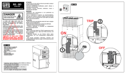
SITOP smart 48V/10A
6EP1 456-2BA00
Betriebsanleitung
Best.-Nr.: C98130-A7583-A1-3-6419
Operating instructions
Instructions
Istruzioni di servizio
Instrucciones
SIEMENS AG ÖSTERREICH, 10.2007
1/8
SITOP smart 48V/10A
Maßbild
Dimension drawing
Encombrement
Dimensioni d´ingombro
Croquis acotado
70
4
125
120
6,2
Hinweis
Diese Betriebsanleitung enthält aus Gründen der Übersichtlichkeit nicht sämtliche Detailinformationen zu allen Typen des Produkts und kann auch nicht jeden
denkbaren Fall der Aufstellung, des Betriebes oder der Instandhaltung berücksichtigen. Weiterführende Hinweise erhalten Sie über die örtliche SiemensNiederlassung bzw. über die Homepage http://www.siemens.com/sitop. Technische Änderungen jederzeit vorbehalten. In Zweifelsfällen gilt der deutsche Text.
Note
These instructions cannot claim to cover all details of possible equipment variations, nor in particular can they provide for every possible example of
installation, operation or maintenance. Further information is obtainable from your local Siemens office or visit our homepage http://www.siemens.com/sitop.
Subject to change without prior notice. The German text applies in cases of doubt.
Note
Pour des raisons de clarté, cette notice ne contient pas toutes les informations de détail relatives à tous les types du produit et ne peut pas non plus tenir
compte de tous les cas d'installation, d'exploitation et de maintenance imaginables. . Pour de plus amples informations, veuillez-vous adresser à votre agence
Siemens ou consultez notre site http://www.siemens.com/sitop. Sous réserve de modifications techniques. En cas de divergences, le texte allemand fait foi.
Nota
Ai fini della chiarezza le presenti istruzioni di servizio non contengono tutte le informazioni dettagliate su tutti i tipi del prodotto e non possono nemmeno
trattare tutti i casi di installazione, di esercizio o di manutenzione. Per ulteriori informazioni rivolgersi alla filiale Siemens di zona o consultare la homepage
http://www.siemens.com/sitop. Ci riserviamo eventuali modifiche tecniche. In caso di differenze o problemi è valido il testo tedesco.
Nota
Por razones de claridad, estas instrucciones no contienen todas las informaciones detalladas relativas a todos los tipos del producto ni pueden considerar
todos los casos de instalación, de operación y de mantenimiento imaginables. Para más información, contacte con la sucursal local de Siemens o visite la
Web http://www.siemens.com/sitop. Sujeto a cambios técnicos sin previo aviso. En casa de duda, prevalece el texto aleman.
SIEMENS AG ÖSTERREICH, 10.2007
2/8
SITOP smart 48V/10A
Deutsch
!
Warnhinweise / Gefahr durch elektrischen Schlag
Beim Betrieb elektrischer Geräte stehen zwangsläufig bestimmte Teile dieser Geräte unter gefährlicher Spannung.
Unsachgemäßer Umgang mit diesen Geräten kann deshalb zu Tod oder schweren Körperverletzungen sowie zu erheblichen
Sachschäden führen. Nur entsprechend qualifiziertes Fachpersonal darf an diesem Gerät oder in dessen Nähe arbeiten. Der
einwandfreie und sichere Betrieb dieses Gerätes setzt sachgemäßen Transport, fachgerechte Lagerung, Aufstellung und
Montage voraus. Vor Beginn der Installations- oder Instandhaltungsarbeiten ist der Hauptschalter der Anlage auszuschalten
und gegen Wiedereinschalten zu sichern. Bei Nichtbeachtung kann das Berühren spannungsführender Teile Tod oder
schwere Körperverletzung zur Folge haben.
Wichtiger Hinweis: Eingangsseitig ist ein Leitungs- oder Motorschutzschalter vozusehen (siehe auch „Eingangsgrößen“)
Achtung
Nur geschultes Personal darf das Gerät öffnen. Elektrostatisch gefährdete Bauelemente (EGB)
Beschreibung und Aufbau
Die SITOP-Stromversorgung 48V/10A ist ein Einbaugerät. Für die Installation des Gerätes sind die einschlägigen länderspezifischen
Vorschriften zu beachten.
Primär getaktete Stromversorgung zum Anschluss an 3-phasiges Wechselstromnetz (TN-, TT- oder IT-Netz nach VDE 0100 T 300 / IEC 3643) mit Nennspannungen 400-500 V, 50/60 Hz; Ausgangsspannung +48 V DC, potenzialfrei, kurzschluss- und leerlauffest.
Technische Daten
6EP1456-2BA00
Eingangsgrößen
Ausgangsgrößen
Schutz- und Überwachungsfunktion
Eingangsnennspannung Ue nenn:
3AC 400-500 V, 50/60 Hz
Ausgangsnennspannung Ua nenn:
DC 48 V ±1% (Auslieferzustand)
Strombegrenzung (Ansprechwert):
1,05…1,2 x Ia nenn
Arbeitsspannungsbereich:
3AC 360…550 V
Alternativ: DC ???...??? V
Einstellbereich: 42…56 V, Einstellung über
Potentiometer an der Gerätevorderseite
(Position siehe Seite 2)
Strombegrenzung dynamisch:
15 A für 5 s/min
Netzausfallüberbrückung bei 400 V:
7 ms
Derating bei Ua >48 V:
4% [Ia]/ V [Ua] (max. 480 W)
Eingangsnennstrom Ie nenn:
1,1-0,9 A
Welligkeit der Ausgangsspannung:
<150 mVss Restwelligkeit
<240 mVss Schaltspitzen
Einschaltstrombegrenzung (25°C):
2
<18 A, <0,8 A s
Vorzuschaltender 3ph. gekoppelter
Leitungsschutzschalter:
6 bis 16 A, Charakteristik C
Ausgangsnennstrom Ia nenn:
10 A
Das Parallelschalten von zwei gleichartigen
Geräten zur Leistungserhöhung ist zulässig.
Verhalten im Kurzschlussfall (Ausgang):
Konstantstrom ca. 11 A
Signalisierung:
LED grün: Ua > ~38 V
Meldesignale:
Potenzialfreier Relaiskontakt für Ua >38 V;
Kontaktbelastbarkeit DC 60 V/0,3 A
Vorschriften und Zulassungen
Schutzart: IP20 nach IEC 529
Schutzklasse 1
Alternativ:
Leistungsschalter 3RV1021-1DA10,
Einstellung des thermischen
Überstromauslösers: 3 A oder
3RV1721-1DD10 (UL489 - Listed)
Umgebung
Temperatur
für Lagerung/Transport: -25°C bis +85°C
für Betrieb:
0 bis +60°C
Sicherheit nach EN 60950: SELV
Sichere elektrische Trennung erfüllt nach
EN 60950 und EN 50178;
Trafo nach EN 61558-2-17
Wirkungsgrad bei Volllast (typisch):
ca. 93%
Feuchteklasse: entsprechend Klimaklasse 3K3
nach EN 60721, Teil 3; keine Betauung
Störaussendung nach EN 61000-6-3
Funkentstört nach EN 55022, Klasse B
Leistungsaufnahme (Wirkleistung):
520 W
Luftselbstkühlung
Störfestigkeit nach EN 61000-6-2;
EN 61000-4-2/-3/-4/-5/-6/-11
Gewicht
CE-Konformität gemäß 2004/108/EG und
2006/95/EG
1,2 kg
cULus (UL 508), File E197259
Montagehinweise
Montage auf Normprofilschiene DIN EN 50022-35x15/7,5. Das Gerät ist zwecks ordnungsgemäßer Entwärmung vertikal so zu montieren,
dass die Eingangsklemmen und die Ausgangsklemmen unten sind. Unterhalb und oberhalb des Gerätes soll mindestens ein Freiraum von je
50 mm eingehalten werden. Der Anschluss der Versorgungsspannung (3AC 400-500 V) muss gemäß IEC 60364 und EN 50178 ausgeführt
werden. Die oben angegebene Schutzeinrichtung (Leitungsschutzschalter oder Leistungsschalter) und Trenneinrichtung zum Freischalten der
Stromversorgung muss vorgesehen werden. Ein FI-Schutzschalter darf als alleinige Schutzmaßnahme bei indirektem Berühren nicht
angewandt werden, dies gilt für das gesamte, vom FI-Schutzschalter geschützte Netz.
Anschluß und Klemmenbelegung
Klemmen
L1, L2, L3
PE
+, –
Funktion
Eingangsspannung 3AC 400-500 V
Schutzleiter
Ausgangsspannung DC 48 V
13, 14
Potenzialfreier Relaiskontakt (Schließer)
für Ausgangsspannung >38 V
SIEMENS AG ÖSTERREICH, 10.2007
Klemmbereich
2
0,2… 4 mm
3/8
Bemerkung
Schraubklemmen; Verwenden Sie einen Schraubendreher mit
4 mm Klingenbreite.
Empfohlenes Anzugsmoment: 1,2 Nm
SITOP smart 48V/10A
English
!
Warning / Danger of electric shock
Hazardous voltages are present in certain parts of this electrical equipment during operation. Incorrect handling of the
equipment can result in death, severe personal injury or substantial property damage. Only qualified personnel are allowed to
work on or around this equipment. The successful and safe operation of this equipment is dependent upon proper transport,
storage and installation. Before installation or maintenance work is carried out, the main switch must be switched off and
locked to prevent it from being switched on again. If these rules are not adhered to, contact with live parts or improper use can
result in death or severe personal injury.
Important Note: Input 3 phase circuit breaker is required! (Refer to “Input Data”)
Caution
The device may only be opened by qualified personnel. Electrostatically sensitive devices (ESD)
Description and construction
The SITOP 48V/10A power supply are built-in units. The relevant local regulations must be observed during installation.
Primary switched-mode power supplies for connection to a 400-500 V, 50/60 Hz three-phase AC system (TN-, TT- or IT-system acc. to
VDE 0100 T 300 / IEC 364-3); output voltage +48 V DC, potential-free, short-circuit resistant and stable under no-load conditions.
Technical specifications
6EP1456-2BA00
Input data
Output data
Input rated voltage Vin rated:
400 to 500 V 3 AC, 50/60 Hz
Output rated voltage Vout rated:
48 V DC ±1% (as delivered)
Voltage range:
360 to 550 V 3 AC
Alternative: ??? to ??? V DC
Setting range: 42 to 56 V, adjustable by
potentiometer on front of device (see page 2 for
position)
Mains buffering time at 400 V :
7 ms
Derating at Vout >48 V:
4% [Iout]/ V [Vout] (max. 480 W)
Response to short circuit (output):
Constant current approx. 11 A
Input rated current Iin rated:
1.1-0.9 A
Ripple content of output voltage:
<150 mVpp ripple
<240 mVpp spikes
Signaling:
Green LED: Vout > ~38 V
Inrush current is limited to (25°C):
2
<18 A, <0.8 A s
Required 3-ph. miniature circuit breaker:
6 to 16 A, characteristic C
Alternative:
circuit-breaker 3RV1021-1DA10, setting of
the thermal overcurrent trip: 3 A or
3RV1721-1DD10 (UL489 - Listed)
Efficiency at full load (typical):
ca.93%
Power input (active power):
520 W
Protection and monitoring
functions
Output rated current Iout rated:
10 A
Current limitation (threshold value):
1.05 to 1.2 x Iout rated
Current limitation dynamic:
15 A for 5 s/min
Signals:
Floating relay contact for Vout >38 V;
contact rating DC 60 V/0.3 A
Two power supplies of identical design may be
connected in parallel in order to improve the
performance.
Standards and approbations
Environmental conditions
Safety to EN 60950: SELV
Safe electrical isolation met in accordance
with EN 60950 and EN 50178;
Transformer corresponds EN 61558-2-17
Temperature:
Storage/transport: -25.to +85°C [-13 to +185°F]
Operating:
0 to +60°C [+32 to +140°F]
Humidity:
according to EN 60721 class 3K3; no
condensation
Natural convection should be allowed to form
Degree of protection IP20 to IEC 529
Protection class 1
Emission to EN 61000-6-3;
RI suppression to EN 55022, limit curve B
Noise immunity to EN 61000-6-2,
EN 61000-4-2/-3/-4/-5/-6/-11
CE marking acc. to 2004/108/EG and
2006/95/EG
Weight
1.2 kg [2.65 lb.]
cULus (UL 508), File E197259
Installation
Mounting on a DIN EN 50022-35x15/7.5 standard rail. To ensure adequate convection, the device must be installed vertically, with the input
and the output terminals at the bottom. Be sure to leave a minimum clearance of 50 mm above and below the device. The supply voltage (3ph. AC 400-500 V) must be connected in accordance with IEC 60364 and EN 50178. It is important to provide the protective device referred to
above (miniature circuit-breaker or circuit-breaker) and the disconnecting device for isolating the power supply. A current-operated earthleakage circuit-breaker must not be the sole device used where protection against indirect contact is required. The same applies for the entire
system protected by a current-operated earth-leakage circuit-breaker.
Connections and terminal assignment
Terminals
L1, L2, L3
PE
+, –
13, 14
Function
Input voltage 3-ph. AC 400- 500 V
Protective earth conductor
Output voltage DC 48 V
Floating relay contact (make contact)
for output voltage Vout >38 V.
SIEMENS AG ÖSTERREICH, 10.2007
Terminal range
2
0.2 to 4 mm
AWG 24 to 10
4/8
Remarks
Screw-type terminals. Use a screwdriver with a blade width of
4 mm.
Recommended tightening torque 1.2 Nm.
SITOP smart 48V/10A
Francais
!
Marques d`avertissement / Danger décharge électrique
Le fonctionnement d´un équipement électrique implique nécessairement la présence des tensions dangereuses sur certaines
de ces parties. Toute utilisation et/ou intervention contraires aux règles de l’art peuvent donc conduire à la mort, à des
lésions corporelles graves ou à des dommages matériels importants. Seules des personnes qualifiées doivent travailler sur
cet appareil ou dans son voisinage. Le fonctionnement correct et sûr de cet équipement présuppose un transport, un
stockage, une installation et un montage conformes aux règles de l´art. Avant le début des travaux d’installation ou de
maintenance, le disjoncteur principal doit être ouvert et condamné pour interdire sa refermeture intempestive. Le non-respect
des consignes de sécurité peut avoir pour conséquence un contact avec une des parties sous tension et conduire à la mort
ou à des blessures graves.
Remarque importante : En entrée, il faut prévoir un disjoncteur de ligne ou un disjoncteur moteur (cf. aussi „Grandeurs d'entrée“)
Attention
L´appareil ne doit être ouvert que par du personell initié. Composants sensibles aux décharges électrostatiques (DES)
Description et constitution
L'alimentation SITOP 48V/10A est un appareil encastrable. L´installation de cet appareil doit se faire en conformité avec les reglementations
nationales.
Alimentations à découpage pour le raccordement au réseau triphasé (réseau TN, TT ou IT selon VDE 0100 T 300 / IEC 364-3) de tension
nominale 400 à 500 V ca, 50/60 Hz; tension de sortie +48 V cc, libre de potentiel, protégée contre les court-circuits et la marche à vide.
Caractéristiques techniques
6EP1456-2BA00
Grandeurs d'entrée
Grandeurs de sortie
Fonctions de protection et de surveillance
Tension d´entree nominale Ue nom:
3ph. 400 à 500 V ca, 50/60 Hz
Tension de sortie nominale Ua nom:
48 V cc ±1% (réglage à la livraison)
Limitation de courant (valeur seuil):
1,05 à 1,2 x Ia nom
Plage de tension:
3ph. 360 à 550 V ca
En variante: ??? à ??? V cc
Plage de réglage: 42 à 56 V, Réglage par
potentiomètre en face avant de l'appareil
(position voir page 2)
Limitation de courant dynamique:
15 A pendant 5 s/min
Temps de maintien sous 400 V:
7 ms
Déclassement pour Ua >48 V:
4% [Ia]/ V [Ua] (max. 480 W)
Courant d´entree nominal Ie nom:
1,1-0,9 A
Ondulation résiduelle:
<150 mVcàc ondulation résiduelle
<240 mVcàc pointes de commutation
Limitation du courant d'appel (25°C):
2
<18 A, <0.8 A s
Disjoncteur tripolaire de ligne amont
caractéristique C:
6 à 16 A
En variante:
disjoncteur moteur amont 3RV1021-1DA10,
Réglage du déclencheur thermique de
surcharge: 3 A, ou 3RV1721-1DD10 (UL489
- enregistrez)
Rendement à pleine charge (typique):
ca. 93%
Puissance absorbée (P active):
520 W
Courant de sortie nominal Ia nom:
10 A
La mise en parallèle de deux appareils du
même type pour augmentation de puissance
est admise.
Comportement sur court-circuit:(en sortie):
Courant constant env.
11 A
Signalisation:
LED verte: tension de sortie Ua > ~38 V
Signaux:
Contact de relais libre de potentiel: Ua >38 V;
Capacité de charge des contacts :
DC 60 V/0,3 A
Prescriptions et certificats
Degré de protection: IP20 selon IEC 529
Conditions d´environnement
Classe de protection 1
Température
stockage et transport:
en service:
Sécurité selon EN 60950: TBTS
Séparation de sécurité des circuits conforme
à EN 60950 et EN 50178;
Transformateur correspond à EN 61558-2-17.
-25 à +85°C
0 à +60°C
Classe d’humidité:
selon EN 60721 classification climatique
3K3, sans condensation
Refroidissement par libre convexion
Poids
Niveau d'émission: EN 61000-6-3,
Antiparasitage selon EN 55022 classe B
Immunité: EN 61000-6-2;
EN 61000-4-2/-3/-4/-5/-6/-11
Conformité CE selon 2004/108/EG et
2006/95/EG
1,2 kg
cULus (UL 508), File E197259
Montage
Encliquetage sur profilé chapeau normalisé EN 50022-35x15/7,5. Pour un refroidissement conforme aux règles l’appareil doit être monté
verticalement d’une telle facon que les bornes d’entrée et les bornes de sortie se trouvent en bas. Au-dessous et au-dessus de l’appareil, on
doit ménager un espacement d’au moins 50 mm. Le raccordement de la tension d’alimentation (3ph. 400 à 500 V ca) doit être réalisé
conformément à IEC 60364 et EN 50178. Un dispositif de protection tel qu'indiqué ci-dessus (disjoncteur de ligne ou disjoncteur moteur) et un
dispositif de sectionnement permettant la mise hors tension doivent être prévus. Un interrupteur différentiel est interdit en tant que disposition
unique de protection contre les contacts indirects; cette interdiction vaut pour tout le réseau protégé par l'interrupteur différentiel.
Bornes et caractéristiques de branchement
Bornes
L1,L2,L3
PE
+, –
13, 14
Fonction
Tension d’entrée 3ph. 400 à 500 V ca
Conducteur de protection
Tension de sortie 48 V cc
Contact de relais libre de potentiel (NO):
tension de sortie Ua >38 V
SIEMENS AG ÖSTERREICH, 10.2007
Section
2
0,2 à 4 mm
5/8
Observations
Bornes à vis. Utiliser un tournevis à lame de 4 mm de
large.
Couple de serrage recommandé 1,2 Nm
SITOP smart 48V/10A
Italiano
!
Pericolo / Pericolo di scossa elettrica
Durante il funzionamento, alcune parti degli apparecchi elettrici si trovano inevitabilmente sotto tensione pericolosa. L’uso
inappropriato di questi apparecchi può quindi causare la morte, gravi lesioni alle persone e ingenti danni materiali. Interventi
sull´apparecchio o nelle sue vicinanze vanno eseguiti solo da personale qualificato. Un funzionamento corretto e sicuro
dell’apparecchio presuppone che il trasporto, il magazzinaggio, l'installazione e il montaggio siano stati effettuati
correttamente. Prima di iniziare lavori di installazione o di manutenzione, occorre disinserire l’interruttore principale e
assicurarsi che non sia possibile una reinserzione. La mancata osservanza o l'uso inadeguato degli apparecchi potrà
provocare la morte o gravi lesioni al contatto con le parti che sitrovano sotto tensione.
Avvertenza importante: in entrata è necessario prevedere un interruttore di linea o un interruttore protezione motore (ved. Valori di
ingresso“)
Attenzione
L´apparecchio può essere aperto solo da personale addestrato. Componenti sensibli alle cariche elettrostatiche (ESD)
Descrizione e montaggio
L´alimentatore SITOP 48V/10A e un` apparecchio a giorno. L´installazione degli apparecchi deve essere effettuata conformemente le
corrispondenti prescrizioni nazionali.
Alimentatore con primario in switching per il collegamento a reti trifase a corrente alternata (rete TN, TT o IT sec. VDE 0100/IEC 364-3) da
400...500 V, 50/60 Hz; tensione d’uscita +48 V DC, con separazione galvanica, resistente a cortocircuito e marcia a vuoto.
Dati tecnici
6EP1456-2BA00
Valori di ingresso
Valori di uscita
Tensione d´ingresso nominale Ue Nom:
3AC 400...500 V, 50/60 Hz
Tensione d´uscita nominale Ua Nom:
DC 48 V ±1% (al momento della fornitura)
Campo di tensione:
3AC 360...550 V
In alternativa: DC ???...??? V
Campo di regolazione: 42...56 V,
Regolazione tramite potenziometro sul lato
anteriore dell’apparecchio (per la posizione
vedere pagina 2)
Intervallo di mancanza di rete ammissibile
con 400 V:
7 ms
Corrente d´ingresso nominale Ie Nom:
1,1…0,9 A
Limitazione della corrente d´inserzione
(25°C):
2
<18 A, <0,8 A s
Interruttore automatico accoppiato trifase da
collegare a monte con caratteristica C:
6...16 A
Derating con Ua >48 V:
4% [Ia]/ V [Ua] (max. 480 W)
Ondulazione della tensione d´uscita:
<150 mVpp ondulazione residua
<240 mVpp picchi di inserzione.
Corrente d’uscita nominale Ia Nom:
10 A
È ammesso il collegamento in parallelo di
due apparecchi dello stesso tipo allo scopo
di aumentare la potenza.
In alternativa:
Ambiente
Salvamotore da collegare a monte 3RV1021Temperatura
1DA10, Impostazione dello sganciatore
per magazzinaggio e trasporto: -25...+85°C
termico di sovraccarico: 3 A,
durante l’esercizio:
0...+60°C
opp. 3RV1721-1DD10 (UL489 - se elenca)
Rendimento a pieno carico (tipico):
ca. 93%
Assorbimento di potenza (potenza attiva):
520 W
Classe umidità:
sec. EN 60721 classificazione climatica 3K3,
Nessuna formazione di condensa
autoraffreddamento ad aria
Peso
Funzioni di protezione e di
sorveglianza
Limitazione di corrente (valore di soglia):
1,05...1,2 x Ia Nom
Limitazione di corrente dinamico:
15 A per 5 s/min
Comportamento in caso di cortocircuito
(uscita):
Corrente costante ca.
11 A
Segnalazione:
LED verde: tensione di uscita Ua > ~38 V
Segnalazione d`esercizio:
Contatto di relè a potenziale libero: Ua >38 V;
Sollecitazione ammessa die contatti:
DC 60 V/0,3 A
Norme e Omologazione
Grado di prot.: IP20 sec. IEC 529
Classe di protezione 1
Sicurezza sec. EN 60950: SELV
Interruzione elettrica sicura realizzata in
conformità alle norme legali EN 60950 e
EN 50178;
Trasformatore corrisponde a EN 61558-2-17
Emissione di disturbi sec. EN 61000-6-3,
Protez. contro radiodisturbi sec. EN 55022,
Classe B
Immunità ai disturbi sec. EN 61000-6-2;
EN 61000-4-2/-3/-4/-5/-6/-11
1,2 kg
Conformità CE secondo 2004/108/EG e
2006/95/EG
cULus (UL 508), File E197259
Istruzioni per il montaggio
Montaggio su guida profilata normalizzata EN 50022-35x15/7,5. Per garantire la dissipazione del calore montare l’apparecchio verticalmente
in modo che i morsetti d’ingresso e uscita siano sul lato inferiore dell’apparecchio. Al di sotto e al di sopra dell’apparecchio dev’essere
osservato uno spazio libero di almeno 50 mm. Il collegamento della tensione d’alimentazione (3AC 400...500 V) deve essere effettuato sec. le
norme IEC 60364 e EN 50178. Devono essere previsti un dispositivo di protezione (interruttore automatico o salvamotore) e un dispositivo di
sezionamento per isolare l’alimentatore. Un interruttore differenziale FI non è sufficiente come unico dispositivo di protezione in caso di
contatto indiretto; questo vale per l'intera rete protetta dall'interruttore differenziale FI
Allacciamento e assegnazione dei morsetti
Morsetti
L1, L2, L3
PE
+, –
13, 14
Funzione
Tensione di ingresso 3AC 400...500 V
Conduttore di protezione
Tensione di uscita DC 24 V
Contatto di relè a potenziale libero (di lavoro):
tensione di uscita Ua >38 V
SIEMENS AG ÖSTERREICH, 10.2007
Val. allacciam.
2
0,2...4 mm
6/8
Annotazione
Morsetti a vite. Impiegare un cacciavite con tagliente di
4 mm.
Coppia di serraggio consigliata 1,2 Nm
SITOP smart 48V/10A
Español
!
Instrucciones preventivas / Peligro por descarga eléctrica
Durante el funcionamiento de los equipos eléctricos, determinadas partes de los mismos se encuentran forzosamente bajo
tensión peligrosa. Por ello, cualquier manipulación incorrecta puede provocar la muerte o lesiones graves asi como daños
materiales considerables. En este equipo o en sus proximidades solo deberá trabajar personal adecuadamente cualificado.
El perfecto y seguro funcionamiento de este equipo presupone que ha sido transportado, almacenado, instalado y montado
correctamente. Antes de comenzar los trabajos de instalación o reparación es preciso desconectar el interruptor principal y
protegerlo contra reconexiones accidentales. De no observarse estas instrucciones, el contacto con partes bajo tensión
puede tener como consecuencia la muerte o lesiones corporales graves.
Nota importante: Por el lado de entrada debe preverse un magnetotérmico o guardamotor (ver también "magnitudes de entrada“)
Atención
Este aparato sólo podrá ser abierto por personal cualificado. El equipo contiene componentes sensibles a las cargas
electroestáticas
Descripción y estructura
La fuente de alimentación SITOP 48V/10A ha sido concebida como aparatos para montar en conjuntos para su empleo en ambiente
industrial. La instalación del aparato deberá realizarse de acuerdo a las normas y reglamentos nacionales.
Fuente de alimentación conmutada conveniente para su conexión a una red trifásica (red en esquema TN, TT o IT según VDE 0100/ IEC 3643) de 400-500 V, 50/60 Hz; tensión de salida +48 V DC, libre de potencial, protegida contra cortocircuitos y funcionamiento en vacío.
Datos técnicos
6EP1456-2BA00
Magnitudes de entrada
Magnitudes de salida
Funciones de protección y supervisión
Tensión de entrada nominal Ue nom:
400-500 V 3 AC, 50/60 Hz
Tensión de salida nominal Us nom:
48 V DC ±1% (ajuste de fábrica)
Limitación de corriente (nivel de percepción):
1,05 a 1,2 x Is nom
Rango de tensión:
360-550 V 3 AC
Alternativa: ???-??? V DC
Rango de adjuste: 42 a 56 V, Ajuste mediante
potenciómetro en el frontal del equipo
(posición, ver pág. 2)
Limitación de corriente dinámico:
15 A durante 5 s/min
Puenteo de fallos de red con 400 V :
7 ms
Derating con Us >48 V:
4% [Is]/ V [Us] (máx. 480 W)
Intensidad de entrada nominal Ie nom:
1,1-0,9 A
Rizado de la tensión de salida:
<150 mVpp de rizado residual
<240 mVpp picos de conmutación
Limitación corriente de conexión (25°C):
2
<18 A, <0,8 A s
Interruptor de protección trifásico
recomendado, característica C:
6 a 16 A
Comportamiento en caso de cortocircuito
(salida): Corriente constante aprox.
11 A
Señalización:
LED verde: tensión de salida Us > ~38 V
Intensidad de salida nominal Is nom:
10 A
Para aumentar la potencia pueden conectarse
en paralelo dos aparatos iguales.
Señales:
Contacto de relé aislado galvánico: Us >38 V;
Capacidad de carga del contacto
DC 60 V/0,3 A
Normas y Homologaciones
Alternativa:
Condiciones ambientales
Grado de protección: IP20 según IEC 529
Guardamotor 3RV1021-1DA10,
Ajuste del disparador térmico: 3 A ó
3RV1721-1DD10 (UL489 - poner en una
lista)
Temperatura para
almacenamiento y transporte: -25 a +85°C
servicio:
0 a +60°C
Clase de protección 1
Rendimiento a plena carga (típ.):
ca. 93%
Potencia (potencia activa):
520 W
Seguridad según EN 60950: SELV
La seguridad de aislamiento eléctrico
Clase de humedad:
conforme a EN 60950 y EN 50178;
según EN 60721 clasificación climática 3K3, sin Transformador corresponde a
condensación
EN 661558-2-17
Refrigeración natural por aire
Emisión según EN 61000-6-3, Supresión de
interferencias radioeléctricas según
Peso
EN 55022, clase B
1,2 kg
Inmunidad según EN 61000-6-2;
EN 61000-4-2/-3/-4/-5/-6/-11
De acuerdo con conformidad del CE
2004/108/EG y 2006/95/EG
cULus (UL 508), File E197259
Montaje
Enganche por resorte en perfil tipo omega normalizado EN 50022-35x15/7,5. Por razones de una refrigeración en forma debida al aparato
debe montarse en posición vertical de modo que los bornes de entrada y de salida serán situados en la parte inferior. Por abajo y por arriba
del aparato, se debe dejar un espacio libre de 50 mm como mínimo. La conexión a la red (400-500 V 3 AC) deberá realizarse conforme a las
normas IEC 60364 y EN 50178. Es preciso prever dispositivos de protección (interruptor automático o guardamotor) y seccionamiento para
aislar la fuente de alimentación de la red, tal como se indica anteriormente. No deberá utilizarse un interruptor diferencial como única medida
de protección en caso de contacto indirecto; esto es válido para toda la red protegida por el interruptor diferencial.
Asignacion de conexiones y bornes
Bornes
L1, L2, L3
PE
+, –
13, 14
Función
Tensión de entrada 400-500 V 3 AC
Conductor de protección
Tensión de salida 48 V DC
Contacto de relé aislado galvánico
(contacto NA): tensión de salida Us >38 V
SIEMENS AG ÖSTERREICH, 10.2007
Sección
2
0,2 a 4 mm
7/8
Observaciones
Bornes de tornillo. Usar un destornillador con hoja de 4 mm
de ancho.
Par de apriete recomendado 1,2 Nm
SITOP smart 48V/10A
Herausgegeben von
SIMEA
Bereich A&D
Siemensstraße 88-92
A 1210 Wien
Siemens AG Österreich
© Siemens AG Österreich All rights reserved.
Liefermöglichkeiten und technische
Änderungen vorbehalten
Best.-Nr.: C98130-A7583-A1-3-6419
Printed in Austria
Stand 10.2007

© Copyright 2026