
1 - American Standard
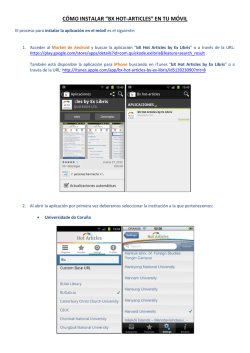
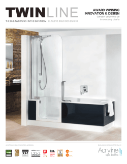
Installation Instructions
Instruccions de Instalación
Install Supports for Tub Spout, Valve Body and Shower
Roughing-In Dimensions
1-5/8" to 2-7/8"
(41 mm à 73 mm)
Finished Wall
Pared Terminada
Ensamble y suelde todas
las conexiones en los
ensambles de la tubería
Shower Arm
Support
1/2" (13mm) I.P.S.
3-7/8" REF. (97mm) REF.
Soporte del brazo
de la ducha
Optional to Finished
Floor Usually
Between 65" and 78"
(1651 a 1981mm)
1/2" NPT
Optativo al Piso Terminado,
Por lo General Entre
65" y 78" (1651 a 1981mm)
6-3/4" REF. (171mm)
74" for Head
Clearance
from Bottom
of Tub
"See Illustration"
De Altura
SHR
Valve Body
pport
74" para el
espacio de la
cabeza desde el
fondo de la tina
Vea la Figura Inferior
74" (188cm)
For Head Clearance
7-5/8" (194mm)
Su
cuerpo
Soporte del vula
de la vál
Optional
1-1/2" REF.
(102 mm) REF.
5-1/8" (130 mm) REF.
Apply Sealing Tape to
all Threaded Connections.
Thread the four Piping Assemblies
to the Valve Body.
4"
(102mm)
Top of Tub Rim
Borde Superior
de la Bañera
3-3/8" (86mm) NPT
Inlets
Fondo de la tina
Ducha
3-3/8"
(86mm)
“SHR” hacia arriba
Bottom
of Tub
1/2" (13mm) NPT
Shower
Entradas
“SHR” Faces Up
Aplique cinta sellante en todas
las conexiones roscadas.
Enrosque los cuatro ensambles
de la tubería en el cuerpo de
la válvula.
4" (102mm)
1/2" (13mm) Cobre
SH
R
Fondo de la Bañera
1/2" (13mm) Copper
2
Optativa
6-1/2" (165 mm)
Optativa
1/2" Cobre
Soportela tina
pico de
(457mm)
18"
(457mm)
Optional
1/2" Copper
out
Tub Spor
Supp det l
18"
TUB
Bottom of Tub
Assemble and Solder
All Connections on
Piping Assemblies
Instale los soportes, el cuerpo de la válvula y la ducha
Dimensions de Desbastado
1/2" (13mm) NPT
Inlets
Entradas
1/2" (13mm) NPT
Tub Port
Threaded Inlets
Entradas Roscadas
Orificio de Bañera
1
Secure the Bath/Shower Assembly to the Supports
3
Turn On Water Supplies and Check all Connections for Leaks.
Turn Off Supplies. Install Plaster Guards and Finish all
Wall Construction.
Asegure el ensamble de la tina/ducha en los soportes
Abra los suministros de agua y revise todas las conexiones en busca
de fugas. Cierre los suministros. Instale las protecciones de masilla
y termine toda
la construcción
de la pared.
Apply Sealing Tape to all
Threaded Connections.
Install Shower Arm, Shower
Head and Spout.
Long End
Extremo largo
Aplique cinta selladora en
todas las conexiones roscadas.
Instale el brazo de la ducha.
SH
R
1-1/2" (38mm)
5
6
R
SH
Remove Plaster Guard and
assemble Cartridge Cap,
Escutcheon and Dial Plate
to Valve Body.
Retire la protección de masilla y
ensamble la tapa del cartucho,
el escudete en el cuerpo y la Placa
de Carátula de la válvula.
Connect Hot and Cold
Water Supplies to
Valve Body
Conecte los suministros
de agua caliente y fría
al cuerpo de la válvula
F
OF
ld
Co
C
F
OF
t
Ho
d
Col
Cold
Hot
Fría
Hot
Caliente
Install Handle
Instale la manija
4
8
7
3
Adjust Hot Limit Safety Stop
1
51
311 5310
97
Turn CARTRIDGE STEM (2) to the OFF position (coldest setting)
before making adjustment to HOT LIMIT STOP (1). Use a flat
blade screwdriver to pry free the HOT LIMIT SAFETY STOP (1).
Pull forward and rotate counterclockwise one number to limit
hot water temperature. Use ARROW (3) on CARTRIDGE (4) and
NUMBERS (5) on HOT LIMIT STOP (1) for indication.
Care and Cleaning:
5
Do: Simply rinse the product clean with clear water, dry with a soft cotton flannel cloth.
Do Not: Clean the product with soaps, acid, polish, abrasives,
1
harsh cleaners, or a cloth with a coarse surface.
Para el Cuidado:
4
Debe: Lavar el producto sólo con agua limpia, secar con un paño suave de algodón.
No Debe: Limpiar el producto con jabones, ácido, productos para pulir, abrasivos,
limpiadores duros ni con paño grueso.
Regule el Limitador de Agua Caliente
Gire el TALLO DEL CARTUCHO (2) a la posición de cierre (OFF, la más fría)
antes de efectuar los ajustes al LIMITADOR DE AGUA CALIENTE (1).
Utilice un destornillador plano para separar el LIMITADOR DE AGUA
CALIENTE (1). Tire hacia fuera y gire en sentido antihorario una posición
para limitar la temperatura del agua caliente. Use la FLECHA (3)
del CARTUCHO (4) y los NÚMEROS (5) del LIMITADOR DE AGUA
CALIENTE (1) como indicadores.
2
Recommended Tools
3
2
Hotter
(Smaller Numbers)
Herramientas Recomendadas
10'
1
5
3
1
1
1
9
Más Caliente
(números menores)
7
5
1
1
3
1
9
7
5
3
1
MÁS FRÍA
(números mayores)
0 1 3 5 7 9 11 13 15
1
15
5
3
4
Colder
(Larger Numbers)
1
0 1 3 5 7 9 11 13 15
M965451_SP_EZ_Rev. 1.4
Grayson™ Pressure Balancing Bath and Shower Sets
7765.502 Series
Grayson™ Juegos de Bañera y Ducha con Presión Equilibrada
7765.502 Serie

© Copyright 2026