
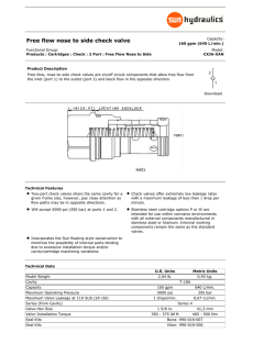
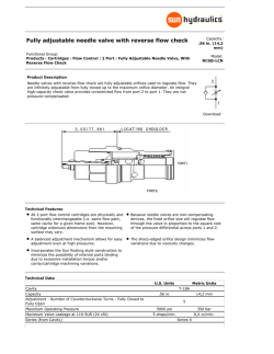
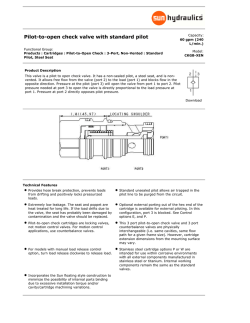
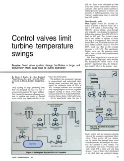
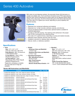
Operating Instructions Automatic Pump Recirculation Valve PSG-N
Holter Regelarmaturen GmbH & Co. KG
Heating, Ventilation, Air Conditioning Valves - Industrial & Power Station Valves
Operating Instructions
Automatic Pump Recirculation Valve PSG-N
Type 75 / 76 / 77
0507 / 111856 / HORA / GB
Contens
Contens
Contens.........................................................................................................1
1.1 Address of Manufacturer.......................................................................................2
1.2 Right to alteration and copyright..........................................................................2
1.3 Validity of operating instructions .........................................................................2
1.4 Safety instructions and regulations .....................................................................3
1.4.1 Meaning of notes ..................................................................................................3
1.4.2 General safety instructions ...................................................................................3
1.4.3 Qualified personnel ...............................................................................................4
1.5 Warranty .................................................................................................................4
1.6 Sectional drawings ................................................................................................5
1.6.1 Sectional drawing example of PSG-N Type 75 and 75-K .....................................5
1.6.2 Sectional drawing example of PSG-N Type 75-T..................................................6
1.6.3 Sectional drawing example of PSG-N Type 76 .....................................................7
1.6.4 Sectional drawing example of PSG-N Type 77 .....................................................8
1.7 Identification of valves ..........................................................................................9
1.7.1 Notes on the nameplate........................................................................................9
1.8 Test pressure .......................................................................................................10
1.9 Special acessories...............................................................................................10
2 Transport, Storage and Handling.........................................................11
3 Description, Technical Data .................................................................12
3.1
3.2
3.3
Function and mode of working...........................................................................12
Intended use.........................................................................................................12
Limitations on use and constructional design of valves..................................12
4 Installing the valve in the system.........................................................13
4.1
4.2
Steps to take before installing the valve in the system!...................................13
Installing the valve ...............................................................................................14
5 Commissioning .....................................................................................15
6 Maintenance ..........................................................................................15
7 Error search list.....................................................................................16
8 Assembly and disassembly instructions ............................................17
8.1 Disassembly / Assembly Type 75, 75-K .............................................................17
8.2 Disassembly / Assembly Type 75-T ...................................................................18
8.3 Disassembly / Assembly Type 76 and 77 ..........................................................18
8.3.1 Stroke setting ......................................................................................................19
8.4 Valve with check valve in bypass (special accessory) .....................................20
8.5 Valves with starting flange (special accessories).............................................20
9 Zertifikat Modul H1 ................................................................................21
1/21
1 General Information
General Information
1.1
Address of Manufacturer
Holter Regelarmaturen GmbH & Co. KG
Helleforthstraße 58-60
D - 33758 Schloß Holte-Stukenbrock
Tel.:
FAX:
e-Mail:
Internet:
1.2
Postfach 14 60
D – 33751 Schloß Holte-Stukenbrock
+49 – (0) – 5207 – 8903 – 0
+49 – (0) – 5207 – 88 037
[email protected]
http://www.hora.de
Right to alteration and copyright
Any regulations, guidelines, norms etc. stated in these operating instructions correspond to the state of
information during preparation and are not subject to alteration services. It is the responsibility of the
operator to ensure that the latest version is used at all times.
The company reserves the right to carry out technical alterations and improvements in connection with any
technical data, statements and images in these operating instructions at any time. Claims for alterations or
improvements on already delivered valves will be excluded.
Copyrights for these operating instructions as well as any rights referring to the possible grant of a patent, or
utility-patented articles, shall remain the property of the manufacturer.
1.3
Validity of operating instructions
These operating instructions only apply to the valves Type 75, 75-K, 75-T. 76 and 77.
Please check that type designation and nameplate of valves match before any measures are taken,
especially when ordering any accessories or spare parts!
The regulations, guidelines and notes referred to in these operating instructions apply to the European
Union. Operators outside the EU are responsible for the observation of the rules as a practical basis for the
handling of the fittings and have to adapt these to the regional / national regulations applicable for the
installation site.
For any additional information, or if you should encounter any special problems which are not dealt with
sufficiently in these operating instructions, please contact the supplier / manufacturer directly.
2/21
1 General Information
1.4
Safety instructions and regulations
1.4.1 Meaning of notes
Hazard:
Attention:
Note:
Signifies that there is a danger of death, severe bodily injury or considerable damage
to property if adequate measures are not taken.
Signifies that there is a threat of damage to property or the environment through noncompliance.
Signifies the hint of a possible advantage when recommendations are followed.
1.4.2 General safety instructions
•
•
•
•
It is the responsibility of the operator that current regulations for labour protection, the prevention of
accidents and EU regulations are observed during the installation, operation and maintenance of any
fittings.
Any persons put in charge of any measures described in these operating instructions must have read
and comprehended these instructions.
Installation, service and maintenance personnel have to practise safe working techniques during any
measures taken and have to avoid any working practices which endanger the safety of persons or valves
or would damage other property in any way.
Before the start of any maintenance and / or repair work, any electric cables leading to any valve
operating gear must be disconnected in accordance with EU regulations by competent personnel. Also
ensure that the valves are free of pressure, cooled down and empty.
Hazard:
The valves are pressurized and hot during operation.
Non-compliance with warning signs could result in death, severe injury or damage to
property.
Only competent personnel (see 1.4.3) must be allowed to work on the valves.
These persons must have thorough knowledge of all warnings, the installation and the repair
measures pointed out in these operating instructions.
The faultless and safe operation of the valves requires professional shipping, storage, installation
and mounting as well as careful, safety-conscious operation and maintenance.
The notes above and the warnings below do not take into consideration any additional regional, local or inhouse regulations of companies and might have to be supplemented by the operator at his own
responsibility.
3/21
1 General Information
1.4.3 Qualified personnel
According to these operating instructions a person is qualified if he/she is familiar with the installation,
mounting, commissioning and operation or maintenance of valves and possesses the recommended
qualifications for the work. The necessary and stipulated qualifications include among other things:
• Training or instruction in accordance with the Standards of Safety Engineering with respect to
maintenance and use of adequate safety and the safety of labour equipment.
• First aid training.
1.5
Warranty
For the extent and duration of any warranties please see "terms and conditions of delivery" supplied by the
manufacturer. At any time the latest version at the date of delivery will apply.
No liabilities will be accepted for damages to valves which are the result of one or more of the following
causes:
• Ignorance of or non-compliance with these operating instructions.
• Insufficiently qualified installation, operating or maintenance personnel.
• Common wear and tear.
• Faulty or careless treatment of the valves.
• Chemical, electrochemical and / or electrical influences.
In addition to this the manufacturer will not accept any liability for:
• Non-compliance with regulations for the safety of labour, prevention of accidents, EU and any other
safety regulations.
• Improper changes or reconstructions of the valves without prior consent by the manufacturer.
• Faulty mounting, faulty commissioning or improper operation.
• Unsuitable or improper application, any other use than the use intended as well as the use under other
than the agreed application conditions.
Any violations against the restrictions above are, in the case of injury to persons or damage to property,
entirely at the operator’s risk.
4/21
1 General Information
1.6
Sectional drawings
The sectional drawings below show examples of the basic construction of valves.
1.6.1 Sectional drawing example of PSG-N Type 75 and 75-K
Both Type 75 and 75-K are mounted in a cast, straight-way type, 3 flange body.
Image 1:
Position
1
2
3
3
4
6
7
10
11
20
Designation
Body
Bypassflange
cover
Start-up flange
seat
(streched/armour plated)
Check valve*
spring *
Bypass bushing*
Non-return valve
Orifice plate
Valve Series Type 75, 75-K
Position
21
22
30
31
50
Designation
Orifice plate
Orifice plate
Stud bolt
Hexagon nut
Sealing *
53
55
70
Sealing
Sealing
Retaining ring
* = spare parts
Table 1:
Parts list for image 1
5/21
1 General Information
1.6.2 Sectional drawing example of PSG-N Type 75-T
Both Type 75-T are mounted in a cast, straight-way type, 3 flange body.
Image 2:
Position
1
2
3
3
4
6
7
10
11
20
21
22
Designation
Body
Bypassflange
Cover
Start-up flange
Seat
(streched/armour plated)
Check valve*
Spring*
Bypass bushing *
Non-return valve
Orifice plate
Orifice plate
Orifice plate
Valve Series Type 75-T
Position
30
31
50
52
53
Designation
Stud bolt
Hexagon nut
Seal *
Ready-made sealing *
Sealing
54
55
56
70
71
Saeling *
Sealing
Stopper *
Retaining ring
Safety element *
* = spare parts
Table 2:
Parts list for image 2
8
6/21
1 General Information
1.6.3 Sectional drawing example of PSG-N Type 76
Both Type 76 are mounted in a cast, straight-way type, 3 flange body.
Position
1
2
3
3
4
5
6
7
9
10
11
12
13
15
16
17
18
19
22
23
Table 3:
Image 3:Valve Series Type 76
Designation
Position
Designation
Body
24
Orifice plate
Bypassflange
25
Orifice plate
Cover
26
Orifice plate
Start-up flange
27
Orifice plate
Seat (streched/armour plated)
30
Stud bolt
Disk
31
Hexagon nut
Bushing
32
Cylinder bolt *
Lever
33
Lockring *
Pin
34
Crown nut *
Seal bushing*
35
Safety element *
Control plug*
40
Spring *
Cage bushing *
41
Spring *
Guide bushing
48
Sealing
Checkvalve *
49
Sealing
Stop bushing *
50
Sealing*
Guide bushing *
51
Sealing *
Ring flange *
52
Sealing *
Tellerfederführung *
53
Ready-made sealing *
Non-return valve
54
Ready-made sealing *
Trestle
60
Retaining ring
* = spare parts
Parts list for image 3
7/21
1 General Information
1.6.4 Sectional drawing example of PSG-N Type 77
Both Type 77 are mounted in a cast, straight-way type, 4 flange body.
Position
1
2
3
3
4
5
6
7
9
10
11
12
13
15
16
17
18
19
22
23
Table 4:
Image 4: Valve Series Type 77
Designation
Position
Designation
Body
24
Orifice plate
Bypassflange
25
Orifice plate
Cover
26
Orifice plate
Start-up flange
27
Orifice plate
Seat(streched/armour plated)
30
Stud bolt
Disk
31
Hexagon nut
Bushing
32
Cylinder bolt *
Lever
33
Lockring *
Pin
34
Crown nut *
Seal bushing *
35
Safety element *
Control plug *
40
Spring *
Cage bushing *
41
Coned disk spring *
Guide bushing
48
Sealing
Check valve *
50
Sealing *
Stop bushing *
51
Sealing *
Guide bushing *
52
Sealing *
Ring flange *
53
Ready-made sealing *
Diskspring guiding *
54
Ready-made sealing *
Non-return valve
60
Retaining ring
Trestle
* = spare parts
Parts list for image 4
8/21
1 General Information
1.7
Identification of valves
On the body or upper part of the valves you will find the following identifications:
• nominal width
• PN / class identification with or without the permissible maximum temperature (TS) or permissible
maximum temperature and permissible maximum pressure as a pair of variates
• material of body
• name of manufacturer (HORA)
• cast number
• product name (Series and/or manufactorer-no.)
• flow direction arrow, if required
• ring joint number, if required
• CE identification (for valves from category I in accordance with 97/23/EU onwards only)
• Spindle stroke in mm and number of adjusting nut revolutions at Type 76 and 77
• manufact-no.
The PN / Class identification in accordance with EN 1092 and EN 1759 sets the minimum and maximum
pressure/temperature limits for the body material.
If the valve has no definite PN or class identification the permissible maximum temperature (TS) and
maximum pressure (PS) are stated as a pair of variates.
The identifications are supplied:
• in integrated form (cast, engraved or stamped on the body or upper part of the valves)
• on a nameplate that is fitted to the body with grooved drive studs
• on note plates (flow arrow, safety notes which definitely have to be observed) which are connected to the
valves in a way that prevents their accidental loss.
1.7.1 Notes on the nameplate
The nameplates provided are made of CrNi steel. Image 5 shows the print (blue / RAL 5010) of the plates.
The additional details are engraved in the nameplates:
Image 5: Nameplate with and without CE-identification
The terms have the following meaning:
• Fab.-No.:
Shows the allocation to a certain order. The engraved number consists of a number
with at least 8 digits. The first two digits show the last two digits of the valves’ year
of manufacture. Example: 02210330 would be a valve from the year 2002 (as on
control valve data sheet)
• Code:
item number of the valve in the system (as on control valve data sheet)
• PSG-N:
Shows the model of valve. (as on control valve data sheet)
• max. TO:
Shows the maximum operating temperature. (as on control valve data sheet)
• CE 0045:
CE identification with code of the stated place 0045 (TÜV Hannover/SachsenAnhalt)
9/21
1 General Information
1.8
Test pressure
For bodies made of cast iron or steel casting with flange connections the maximum permissible pressure is
determined by the appropriate pressure level (EN 1092, EN 1759). The test pressure would therefore be the
1.5-fold of the permissible pressure at room temperature.
If in addition to this the customer has stated outlay values for pressure and temperature, or if no other values
exist, the formula below would be relevant:
• PT = 1.5 * PS/t * Rp0.2 / Rp0.2/t
For this applies:
• PT
Test pressure
• PS/t
permissible maximum pressure (outlay pressure supplied by customer)
• Rp0.2
0.2% expansion limit at 20°C
0.2% expansion limit at temperature TS in °C (outlay temperature supplied by customer)
• Rp0.2/t
If the generated test pressure deviates from the previously stated, the body will additionally show the
generated test pressure (PT).
1.9
Special acessories
Possible special accessories might be:
•
•
Start-up flange
Non-return valve in bypass
10/21
2 Transport, Storage and Handling
2 Transport, Storage and Handling
Please observe the following rules when transporting or storing the valves:
• Store the valves in a dry place until installation.
• The transport and storage temperature should be kept between –20 °C und +65 °C.
• Protect the valves against force (impact, shock, vibrations etc.).
• Any damages to corrosion protection (paintwork, oiled surfaces etc.) are to be remedied immediately.
• Do not store more than 6 months.
• The drain plugs fitted in the interior of the valves for the protection of the flanges must not be removed
before reaching the installation site.
For valves over 25 kg make sure that mounting rings for chain hoists are fitted at an adequate height above
the installation site. It would be even better if sliding rails or swivel arms with a hoist were available at the
installation site.
Image 6 shows examples of handling methods during the fitting of valves.
Place the straps around inlet and outlet flange of the body. Connect the valve to pump outlet flange and main
line. Please ensure that the right sealings (not included in delivery) are placed between the flanges. Finally
connect the bypass pipe to the valve
a (vertical assembly)
b (horizontal assembly, bypass horizontal)
c (horizontal assembly,
bypass vertical downwards)
Illustration 6: Lifting the valve for assembly/disassembly in the pipeline.
11/21
3 Description, Technical Data
3 Description, Technical Data
3.1
Function and mode of working
HORA-PSG-N-Valves protect feed water tanks by constantly maintaining required minimum flow. For this
purpose a part of flow is led back to the pump, if operating flow volume is less than required minimum flow
volume of the pump.
In order to keep the energy loss to the bare minimum, the bypass of HORA pump safety valve should be
opened only wide enough to maintain the required minimum pump flow.
While closing the main line to boiler the full minimum flow volume passes through the bypass.
In addition to this the valve serves as check valve for main line (not for bypass line). Optionally a check valve
can be integrated into the bypass.
3.2
Intended use
Valves of the product line described here are used for maintaining the minimum volume required by the
pump, for reducing the pressure of liquids and for blocking the main line in the pump direction. Pressure in
bypass is reduced in single-stage or multiple-stage method. The valve may be used only in the previously
mentioned pressure and temperature range and for operational data specified in the specifications sheet
(see also chapter 1.8).
Each use for any other task deviating from the abovementioned agreed use as well as an operation higher
than the allowed pressure and temperature proportions will be not be considered as agreed use. Only the
operator is responsible for risks towards humans or devices as well as other property.
The use intended also includes the compliance with regulations for the prevention of accidents and EU
regulations as well as safety-conscious working practices during any measures described in these operating
instructions while observing generally accepted rules of engineering.
The control valve data sheet is part of these operating instructions. If it is not enclosed please apply for it
before commissioning and compare it with the system identifications. Deviations from the system and
specification identification need to be clarified with the manufacturer before commissioning.
3.3
Limitations on use and constructional design of valves
Hazard
These state-of-the-art valves will be operative for the use intended and for operation in accordance
with the agreed, and the data stated on the nameplate. Operatibility might be impaired and result in
hazards to persons and property if:
• installation, setting and / or commissioning is not professionally carried out in accordance with
these operating instructions.
• the valve is operated at pressures and temperatures outside the values shown on the
nameplate.
• the valve is operated under environmental conditions with higher or lower than usual values
(atmospheric temperature, air humidity, dampness etc.).
• unsuitable or faulty accessories or spare parts are used.
Only use original accessories and spare parts!
12/21
4 Installing the valve in the system
4 Installing the valve in the system
Hazard
Safe operation of the valve requires proper installation and commissioning by competent persons in
accordance with the warnings of these operating instructions.
Special attention needs to be paid to general installation and safety regulations for heating,
ventilation, air condition and pipe systems as well as the proper use of tools, welding devices and
personal as well as other safety equipment.
Non-compliance might result in death, severe physical injury or substantial damage to
property!
4.1
Steps to take before installing the valve in the system!
To remove scale, welding residue and other impurities, the system is usually rinsed and a caustic agent
applied before running a service trial.
Before taking these measures pay attention to the following points:
• If possible, the valve should be replaced by a matching piece during rinsing and use of the caustic agent.
• If this is not possible, remove the internal members of the valve and rinse at low pressure. Please read
assembly and disassembly instructions (Chapter 8) for disassembly the inner parts. Note: Switch off
pressure reversing and reducing functions while removing the inner parts.
• If this is not possible, the customer / planner has to arrange for the valve material to be tested for
resistance to caustic agents. If nessesarry we supply a sectional drawing with parts list and details on
materials.
• The valve has to be kept in 100% off-position during cleaning; do not use it for control purposes of any
kind.
Special inserts for control purposes are available for delivery after details of cleaning operation data
have been supplied.
• Rinsing and operations using caustic agents might result in danger to the interior of the valve through
foreign matter and excessive differential pressures. In addition to this, acidic residues in the packing
between the guides and hollow spaces might lead to damage in the course of time.
Damages arising from rinsing and the use of caustic agents can lead to enforced idleness of the system
and will prove very costly. For this reason take the following steps after completing the service trial (to
ensure uninterrupted operation in the interest of the operator): all valves must be
a) opened and checked for damages. (see installation instruction)
b) repaired and parts renewed, as necessary. (see installation instructions)
c) properly installed and the packing of valves treated with caustic agents, renewed. (see installation
instructions)
• In case of lasting impurities of the medium install a dirt pan with mesh width of 0.25 to 0.5 mm in the
suction pipe, as solid material can block the movement of internal members of the valve.
Hazard! Valves are pressurized! Improper dismantling of the valve operating gear or
valve might result in a health hazard!
13/21
4 Installing the valve in the system
In addition to this check the following before installing the valve:
• Do nominal and operating data shown on the nameplate match the operating data of the system?
The manufacturer will not be liable to the substantial damage to the valve that can result from differing
data.
• Is there enough space for installation or disassembly (chain hoists for installation etc.) at the installation
site?
• Has the pipeline been rinsed and cleaned before installation? If this is not the case the manufacturer will
not be liable for any resulting damages.
• Does the distance between the pipe ends correspond to the valve construction length?
• If the optimal installation position of the valve, i.e. with vertically placed valve spindle, is not given, please
contact the manufacturer to discuss possible measures to be taken with respect to actuation forces.
• Is the pipeline set up in a way that mechanical stresses (e. g. forces and torques from pipeline expansion
during operation, vibrations etc.) during installation and operation will not affect the valve body? (possible
availability of compensators).
• Does the piping allow the continuous draining of condensate to avoid water hammer.
•
Note: A straight pipe or damping section with length approx. 10 x DN before and after the valve
will warranty control performance.
•
Note: To carry out installations during operation of the valve, fit leak proof fittings and a bypass at
an appropriate distance before and after the valve. The valved-off section of pipe must be drained.
Attention! If a slider or a ball valve is installed in the bypass line, this should be locked in the
open position under any circumstances before start up.
4.2
Installing the valve
Please pay attention to the following details during installation:
• Remove the safety flaps directly before installation.
• Ensure that the flow arrow on the body matches the flow direction of the pipeline. A reverse flow
direction can cause damages to pump!
• That the bypass line is laid as specified in the specification sheet. It is not allowed to position the bypass
line vertically upwards.
• The valve should be mounted directly on the pump outlet. If the distance is larger than 1.5 meters, inform
the manufacturer about planned position for considering while designing the valve.
• Ensure that the pipelines are connected free of stress, without offset, mismatch or longitudinal shifting.
• Ensure that only matching seals, screws and nuts (not included in delivery) are used for the flange
fittings.
• For welded-in valves, ensure that any work is carried out in accordance with the current regulations for
welding work. Do not attach polarization to the valve as the flow of current might damage important
sliding pieces. After welding is completed the pipeline will once again require cleaning. (The on-site
welding operations are not included in delivery. The valve will have to be opened and any foreign matter
removed. (see installation instructions)
•
•
Note: Remove the internal members before welding!
Ensure the proper attachment of any other connections to the valve.
Valves and pipelines operated at high (> 50 °C) or low (< 0°C) temperatures must be safeguarded against
touch with insulation, and appropriate warnings have to be attached to point out the hazards caused by
touch. The insulation will also absorb sounds.
14/21
5 Commissioning/Maintenance
5 Commissioning
•
•
Hazard! Before commissioning a new system, after alterations and repairs check that:
all installation and mounting work has been finished properly!
safe operation of the valve without hazards to persons or devices or the system is ensured!
Please also ensure the following:
• Increase the main flow gradually by opening the operating line during start up (when the medium is flown
through the valve) and finally close the operating line gradually again. When the operating flow
approaches the required minimum flow of the pump, the bypass must open. (Detectable due to heating
of bypass line or use a technical stethoscope) The bypass flow must increase for a further reduction of
operating flow. If the operating line is closed, the bypass flow has reached the required minimum flow
volume. Finally let the main flow rise to its maximum value. Now the bypass line is closed.
Attention: Product lines Type 75 do not seal 100 % in this range. A little leakage is still there)
•
Observe the valve.
•
Fill the line with appropriate medium before start up.
•
Bypass line must have a guaranteed free passage for flow and preferably should not contain any other
valves besides a check valve.
•
If a slider or a ball valve is installed in the bypass line, this should be locked in the open position.
•
Make sure that the valve interior is neither exposed to excess differential pressure nor to any medium
rendered impure by scale, welding residue, sand etc.
•
Tighten possible loose cover and flange sealings as described in Chapter 8.
•
Leaking gaskets have to be replaced with new gaskets.
•
During operation through the manual start-up line (special accessories), the bypassline must be closed.
The manual start-up line must be opened. The start-up line must have a guaranteed free passage for
flow and preferably should not contain any other valves. If a slider or a ball valve is installed in the startup line, this should be locked in the open position.
6 Maintenance
Inspect the valves once a year (if necessary together with the pump inspection) and check the internal
members for damages.
Check all parts for abrasion, cavitations, erosion or in case long standstills for corrosion.
Replace damaged and/or worn parts and sealings.
15/21
7 Error search list
7 Error search list
Error
No.
Pump
is
running 1.1
backwards
continuous bypass
volume at skin load
Fluctuation in the
system
•
Possible causes
inner parts are blocked by •
impurities
•
Measures
clean internal parts
if necessary use a filter or clean
1.2
•
internal parts are damaged •
replace damaged parts
2.1
•
design conditional leakage •
volume for Type 75, 75-K
Enquire the manufacturer about leakage
volume and compare
2.2
•
operating data does not •
match with data specified
in specification sheet
•
adhere to operating data
clean internal parts
inform supplier / manufacturer
2.3
•
internal
polluted
2.4
•
internal parts are damaged •
replace internal parts
3.1
•
minimum volume of pump •
is too low
inform supplier / manufacturer
3.2
•
Filter polluted
3.3
•
operating data does not •
match with data specified
in specification sheet
•
correct operating data
internal parts are damaged •
replace internal parts
3.4
•
members
are •
•
16/21
Clean or replace the filter
inform supplier / manufacturer
8 Assembly and disassembly instructions
8 Assembly and disassembly instructions
Hazard!
Before starting any work take the following steps:
• Work properly in accordance with EU safety regulations as well as the warnings and
notes shown in these operating instructions.
• Valves are pressure devices! Each improper opening of the valve can be dangerous to
your health! The system should be pressure-less and dry before disassembly.
• Switch off the pump.
• Lock the pipeline on both sides of the valve (valving-off of inlet/outlet of pipe section).
• Depressurize the pipe section (even if only dismantling the actuator).
• Allow the valve to cool down to room temperature.
• Seek information e. g. on the safety data sheet (EU directive 91/155/EWG) about the pipe
content and in all cases of hazardous material (EU directive 67/548/EWG) empty the pipe
section. Observe regulations on personal safety equipment stated on the safety data
sheet.
• Wipe up leakages, e. g. on the valve stem immediately and / or collect substantial
amounts or residue of medium in a suitable container.
• Dispose of medium residue in accordance with EU directive 75/442/EWG.
Note: It is possible to disassemble the internal members without removing the valve from pipe.
8.1
Disassembly / Assembly Type 75, 75-K
(see image 1)
The valve (diagram 1) consists of a body (1) with screwed in bypass flange (2) and cover (3). The cover is
screwed on the body with stud bolts (30) and hexagonal nuts (31). The bypass bushing (10) is screwed into
the bypass flange (2) or body (1). The checkvalve (6) is lead in to the bypass bushing (10) area. Flat
sealings (50 + 53) or if required standard O rings can be used on the outside for sealings. In addition there is
a pressure spring (7) and a seat ring (4) in the valve. Depending on the manufacturing seat rings (not
replaceable) are available in stretched or armour plated version.
Please proceed as follows:
•
Loosen hexagonal nuts (31)
Danger! Cover is under preload spring force, if necessary use assembly tools.
•
The cover (3) can be still impinged with a pressure force, if the hexagonal nuts (31) are already loosened
up to the end of the stud bolts. Please check, whether the cover can be pressed back by hand, otherwise
use assembly tools. For this purpose screw two opposite stud bolts out of the body and replace with two
longer stud bolts if not already available. Screw on hexagonal nuts on the long stud bolts and finally
release the cover and remove.
17/21
8 Assembly and disassembly instructions
Danger! Note cover weight and if necessary hang up the cover in hoist.
•
Take pressure spring (7) from the valve.
•
Pull out the checkvalve (6) from the bypass bush for this and if necessary screw threaded rod (not
included in delivery) into existing thread holes on the front side of the checkvalve for better handling.
Danger! Note the checkvalve weight, if necessary request for assembly tool for horizontal checkvalve
or support the checkvalve. Hang up in the hoist as soon as possible.
•
Take the checkvalve out of the valve.
•
Screw the bypass bushing (10) out of the body with a socket spanner (not included in the delivery).
•
Clean all parts, test and if necessary exchange and install again in the reverse sequence. Replace the
cover sealing under any circumstances!
•
Replace the sealing (53) (if available, versions with seal weld is also an option) only if a leakage is visible
between cast body (1) and bypass flange (2).
8.2
Disassembly / Assembly Type 75-T
(see image 2)
•
Read and follow the disassembly instructions of Type 75 for disassembly the cover.
•
Take pressure spring (7) from the valve.
•
Take the sealing ring (71) out of the checkvalve and remove stoppers (56).
•
Screw the bypass bushing (10) out of the body with a socket spanner (not included in the delivery). Take
bypass bushing (10) and checkvalve (6) out of the valve.
•
Clean all parts, test and if necessary exchange and install again in the reverse sequence. Replace the
cover sealing under any circumstances!
•
The assembly takes place in the reverse sequence.
8.3
Disassembly / Assembly Type 76 and 77
(see Image 3 and 4)
Loosen hexagonal nuts (31) and remove the cover (3).
18/21
8 Assembly and disassembly instructions
Danger! Cover is under preload spring force, if necessary use assembly tools.
•
The cover (3) can be still impinged with a pressure force, if the hexagonal nuts (31) are already loosened
up to the end of the stud bolts. Please check, whether the cover can be pressed back by hand, otherwise
use assembly tools. For this purpose screw two opposite stud bolts out of the body and replace with two
longer stud bolts if not already available. Screw on hexagonal nuts on the long stud bolts and finally
release the cover and remove.
•
After removing the spring (40) and the safety element (35), the adjusting nut (34) can be removed from
the control plug (11).
•
Remove the disc (5) and the bushing (6) (including three levers 7) from the body with two screwdrivers
or withdrawal tool (not included in the delivery) (bush 6 does not have a rim for this purpose).
•
Remove the complete return checkvalve from the valve body. This subassembly consists of:
1
Return checkvalve (15), bar sealing (53, 54), stop bushing (16), guide bushing (17) , flange (18), spring
2
unit (41), cylinder bolts and lockrings (32, 33) or countersunk screws (32) .
1) available according to nominal diameter
2) available according to pressure level
•
The standard unit consisting of seal bushing (10), control plug (11), cage/perforated plate (12), bar
sealing (53, 54) and O-ring (52) can be screwed out of the body only with a socket spanner (special tool
not included in delivery).
•
Unscrew the cage (12) from the adjustment bush.
•
Pull off the adjustment spindle (11) in the flow direction from the adjustment bush (10).
•
Remove the flange (18), the stop bushing (16) and if necessary guide bushing (17) by loosening the
fastening screw (32) from the return checkvalve (15).
•
Clean all parts, test and if necessary exchange and install again in the reverse sequence.
•
It is absolutely necessary to inspect particularly the control plug (11) (cascade area) and the seal
bushing (10) for damages caused by cavitations.
•
Replace damaged and/or worn parts and sealings.
•
Re-assembly is carried out in reverse order.
•
Check the right stroke of the adjustment spindle before locking the cover.
•
Correct the stroke if necessary with the adjusting nut (34).
Attention: Wrong stroke setting leads to damages!
8.3.1 Stroke setting
•
Remover only the cover for setting the stroke. (refer to cover disassembly)
•
The cover (3) can be removed from valve body (1) after loosening the hexagonal nuts (31)
•
Remover spring (40) and take out the safety element (35)
•
Loosen the seal bushing (34) from the control plug.
19/21
8 Assembly and disassembly instructions
Note:
This indicates that the shift point and the max flow volume can also be adjusted. On request
the adjustment can take place on-site (within tolerances).
•
Turn the adjusting nut (34) on the control plug (11) until the cascade area of the spindle has reached the
seat in the seal bushing (10).
•
Now turn the adjusting nut (34) for specified revolutions in the reverse direction according to the
specifications of the manufacturer.
•
At last the adjusting nut (34) must be fixed in the new position with a safety element. If it is not possible
to lock it, because the boring in control plug is out of the range of castle nut, place appropriate plain
washers under the castle nut. At last you can reset the stroke.
Depending on the process data, stroke and number of revolutions (rpm) is provided on the cover (3).
8.4
Valve with check valve in bypass (special accessory)
The check valves are to be replaced only if function troubles are noticed. Conduct a optical check during
annual inspection (by opening the cover) and/or check with a rod, whether the hood is still closing with a
sound. If the check valve needs to be replaced, proceed as follows:
•
Loosen the flange connection from the valve and pipelines and rotate the valve until it is disassembled. If
this is not possible, remove the valve from the pipeline.
•
Remove sealing ring and pull check valve from the bypass.
•
Check and if necessary replace
8.5
Valves with starting flange (special accessories)
Rinse off or remove the starting line for the valves provided with a starting flange. The starting flange is
disassembled according to same instructions as for the cover disassembly.
20/21
9 Certificate Modul H1
9 Certificate Modul H1
21/21
© Copyright 2026