
Masoneilan 87/88 Series Spring Diaphragm Actuator Instructions
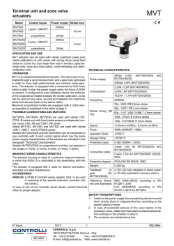
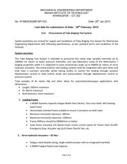
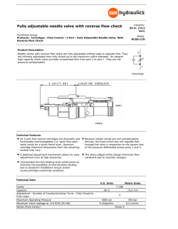
Instruction ER8788
06/97
Masoneilan 87/88 Series
Spring Diaphragm Actuator
Instructions
For complete listing of parts refer to Masoneilan publication FR8788
Instruction ER8788 06/97
87/88 Actuator
TABLE OF CONTENTS
8.
Actuator Range . . . . . . . . . . . . . . . . . . . .7 - 8
1.
Introduction . . . . . . . . . . . . . . . . . . . . . . . . . . .2
2.
General . . . . . . . . . . . . . . . . . . . . . . . . . . . . . .2
3.
Actuator Description . . . . . . . . . . . . . . . . . . . .2
9.
Air Action Changes . . . . . . . . . . . . . . . .8 - 10
4.
Unpacking . . . . . . . . . . . . . . . . . . . . . . . . . . . .2
10.
5.
Air Piping . . . . . . . . . . . . . . . . . . . . . . . . . . . . .2
Actuator Installation on Valve Body
and Plug stem Adjustments . . . . . . . . .10 - 11
6.
Actuator Removal . . . . . . . . . . . . . . . . . . .3 - 4
Parts Reference . . . . . . . . . . . . . . . . . . . . .12
7.
Maintenance . . . . . . . . . . . . . . . . . . . . . . .4 - 7
Table 4 . . . . . . . . . . . . . . . . . . . . . . . . . . . . .13
Tables 1, 2, 3 . . . . . . . . . . . . . . . . . . . . . . . . .7
The following instructions should be thoroughly reviewed and understood prior to installing,
operating or performing maintenance on this equipment. Throughout the text, safety and/or
caution notes will appear and must be adhered to strictly; otherwise, serious injury or
equipment malfunction could result.
1st Digit
2nd
8
Actuator Type
87
88
Air to Close (extend stem)
Air to Open (retract stem)
1. INTRODUCTION
3. ACTUATOR DESCRIPTION
The following instructions are designed to assist maintenance
personnel in performing most of the maintenance required on
the Model 87/88 actuator. Masoneilan has highly skilled service
engineers available for start-up, maintenance and repair of our
actuators and component parts. In addition, a regularly
scheduled training program is conducted at the Training Center,
to train customer service and instrumentation personnel in the
operation, maintenance and application of our control valves
and instruments. Arrangements for these services can be made
through your Masoneilan Representative or Sales Office. When
performing maintenance, use only Masoneilan replacement
parts. Parts are obtainable through your local Masoneilan
Representative or Sales Office. When ordering parts, always
include Model and Serial Number of the unit being repaired.
The 87/88 Series are pneumatic spring diaphragm actuators
which feature field reversibility (with no additional parts).
Because of its multiple spring design, four standard spring
ranges are achieved by varying spring quantity and placement.
A molded rolling diaphragm and deep cases minimize area
change, effecting a linear relationship between travel and air
pressure.
Caution: For full automatic operation, the handwheel
must be placed in the neutral position. If the handwheel
is not in the neutral position, travel will be limited.
4. UNPACKING
Care must be exercised when unpacking the equipment to
prevent damage to the accessories and component parts.
Should any problems arise, contact your Masoneilan
Representative or District Office.
2. GENERAL
5. AIR PIPING
These installation and maintenance instructions apply to the
Masoneilan Model 87/88 actuator regardless of the valve body
on which it is used. Actuator part numbers and recommended
spare parts required for maintenance are listed in the Part
Reference Table on page 12. The model number and action of
the actuator are shown as part of the model number listed on
the identification tag located on the actuator.
© 1997 Dresser Industries, Inc. All rights reserved.
The Model 87/88 actuator is designed to accept 1/4" NPT air
supply connections. If the actuator has been supplied with
accessories, they are piped at the factory.
Caution: Do not exceed pressure indicated on identification tag.
2
Instruction ER8788 06/97
87/88 Actuator
6. ACTUATOR REMOVAL
6.3 Air to open (Model 88), size 6, no handwheel
(Figures 2 and 4)
Maintenance on the valve body normally requires removal of the
valve actuator. The steps in removal of the actuator are different
depending on whether the actuator is air to close or air to open.
Since removal of the valve plug stem from the actuator stem
connector requires that the valve plug be off the seat, special
provisions are necessary to assure that the valve is in the
opened position. The actuator do not being equipped with a
handwheel, proceed as follows:
Note: Actuator action may be checked by referring to the valve
identification tag. Model 87 indicates unit is air to close and
Model 88 indicates unit is air to open.
Note: Since air supply piping connected to the actuator is
normally rigid and the actuator will be moved, it is required that
a manual loading panel with suitable flex tubing be used or
some suitable type of flex connections be made between the
supply piping and the actuator connection.
6.1 Air to close (Model 87), size 6, with or without
handwheel (Figure 2)
A. Shut off air supply to actuator and rotate handwheel to
the neutral position. [No force exerted on the stem
connector by the pivot pins (33)].
Caution: Unreasonably high stress placed on rigid
piping could cause breaking of the air supply line. A
flex connector is required.
B. Disconnect air piping from diaphragm case.
C. Check the travel indicator (7) against the travel scale
(9) to insure that the plug is up (off the seat).
A. Shut off air supply to the actuator.
B. Disconnect air supply piping to the actuator.
Note: No air pressure is required to the actuator since
the spring pressure tends to open the valve.
D. Loosen stem lock nuts (1).
C. Connect manual loading panel tubing to the lower
diaphragm case tubing connector.
E. Re-tighten lock nuts (1) against each other so they
will lock at a point that is not against the stem
connector (2).
D. Apply required air pressure through the manual loading
panel to open the valve as is indicated by the travel
indicator (7) and travel indicator scale (9).
Caution: Do not exceed pressure indicated on the
tag (63) on the diaphragm case.
Caution: At this time provisions must be made to
support and lift the actuator off the body using
recommended lift supports and procedures.
E. Loosen stem lock nuts (1).
F. Loosen and remove drive nut.
F. Re-tighten stem lock nuts (1) against each other so
they will lock at a point that is not against the actuator
stem connector (2).
Caution: Depending on stem length, it may be
required to slightly raise the actuator off the body
to enable the plug stem to disengage from the
actuator stem. The actuator must be raised straight
off the body to prevent stress on the plug stem.
Caution: At this time provisions must be made to
support and lift the actuator off the body using
recommended lift supports and procedures.
G. Turn the stem lock nut (1) counterclockwise and loosen
the plug stem until it disengages from the actuator
stem (10).
G. Loosen and remove drive nut.
Caution: Depending on stem length, it may be
required to slightly raise the actuator off the body
to enable the plug stem to disengage from the
actuator stem. The actuator must be raised straight
off the body to prevent stress on the plug stem.
Note: Do not allow the valve plug to drop or turn
against the seat ring, as this could damage the seat
and plug.
H. Remove actuator from the valve body.
H. Turn the upper stem lock nut (1) counterclockwise and
unscrew the valve plug stem until disengaged from the
actuator stem (10).
Caution: Care should be taken in handling the
actuator to prevent damage to gauges, tubing,
and component parts.
Note: Do not allow the plug to drop or turn against the
seat ring. This could damage the seat and plug.
I. Remove actuator from the valve body and shut off air
supply pressure.
6.2 Air to open, Model 88, size 6, with handwheel
Caution: The stem connector (2) on this size is not fixed
to the actuator stem and is a loose part with the plug
stem removed. For safety, the handwheel must be in a
free position and the actuator removed from the valve
using procedure 6.3 Air to Open without handwheel.
Caution: Care should be taken in handling the
actuator to prevent damage to gauges, tubing, and
component parts. In addition, since a flex connection is made between the actuator and air piping,
care must be taken not to exert pressure on the flex
tubing or air piping.
3
Instruction ER8788 06/97
87/88 Actuator
E. Loosen stem lock nuts (1).
6.4 Air to close (Model 87), sizes 10-23, with and
without handwheel (Figure 3)
F. Remove cap screws (5) from stem connector (2, 4).
A. Shut off air supply to actuator and rotate handwheel to
the neutral position.
Note: Do not allow the valve plug to drop or turn
against the seat ring, as this could damage the seat
and plug.
B. Disconnect air piping from diaphragm case.
C. Check the travel indicator (7) against the travel scale
(9) to insure that the plug is up (off the seat).
Caution: At this time provisions must be made to
support and lift the actuator off the body using
recommended lift supports and procedures.
Note: No air pressure is required to the actuator since
the spring pressure tends to open the valve.
G. Loosen and remove drive nut.
D. Loosen stem lock nut (1).
E. Remove cap screws (5) from stem connector (2, 4).
Caution: Progressively raise actuator off the body
to enable the top stem connector (4) disengage the
bottom stem connector (2). The actuator must be
raised straight off the body to prevent stress on the
plug stem.
Note: Do not allow the valve plug to drop or turn
against the seat ring, as this could damage the seat
and plug.
Caution: At this time provisions must be made to
support and lift the actuator off the body using
recommended lift supports and procedures.
H. Remove bottom stem connector parts (1, 2, 6) from
plug stem.
I. Remove actuator from the valve and shut off air supply
pressure.
F. Loosen and remove drive nut.
Caution: Progressively raise actuator off the body
to enable the top stem connector (4) disengage the
bottom stem connector (2). The actuator must be
raised straight off the body to prevent stress on the
plug stem.
7. MAINTENANCE
Caution: It is recommended that disassembly or
assembly work on these actuators be done in an
upright position.
G. Remove bottom stem connector parts (1, 2, 6) from
plug stem.
H. Remove actuator from the valve.
7.1 Replacing diaphragm air to open actuators (Model
88) with or without handwheel (Figure 4)
6.5 Air to open, Model 88, Size 10-23, with or without
handwheel (Figure 4)
A. Shut off air supply to the actuator, isolate the control
valve process pressure to eliminate the valve from
moving with spring tension removed.
Since removal of the valve plug stem from the actuator stem
connector requires that the valve plug be off the seat, special
provisions are necessary to assure that the valve is in the
opened position. Proceed as follows:
B. If valve is equipped with a handwheel, rotate handwheel to a neutral position.
Note: Since air supply piping connected to the actuator is
normally rigid and the actuator will be moved, it is required that
a manual loading panel with suitable flex tubing be used or
some suitable type of flex connections be made between the
supply piping and the actuator connection.
C. Remove diaphragm case cap screws and nuts (20
and 19).
Caution: Diaphragm case is under spring tension
and is equipped with tension bolts (27, 28 and 56)
which must be removed last.
Caution: Unreasonably high stress placed on rigid
piping could cause breaking of the air supply line. A
flex connector is required.
D. Remove tension bolts (27, 28 and 56) in multiple steps
to relieve spring tension gradually. Remove upper
diaphragm case (24).
A. Shut off air supply to the actuator and rotate handwheel to the neutral position.
E. Note position of springs (21) and spring spacers (18)
[if equipped] in the diaphragm plate (26), before to
remove these parts.
B. Disconnect air supply piping to the actuator.
C. Connect manual loading panel tubing to the lower
diaphragm case tubing connector.
F. Remove cap screw (23) [size 6] or jam nut (23)
[all other sizes] and diaphragm washer (22) [all sizes].
D. Apply required air pressure through the manual loading
panel to open the valve as is indicated by the travel
indicator (7) and stroke scale (9).
G. Remove diaphragm plate (26) and diaphragm (25).
H. Replace the new diaphragm (25) on the diaphragm
plate (26).
Caution: Do not exceed pressure indicated on the
tag (63) on the diaphragm case.
I. Size 6 actuator coat the threads of cap screw (23) and
4
Instruction ER8788 06/97
87/88 Actuator
mounted through the yoke and secure the handwheel
pivot (36) in place (see Figure 7).
D. Let the complete handwheel assembly swing down and
out of the way of the top stem connector (4) [bottom
stem connector (2) on size 6 actuator].
E. Proceed with the instructions for air to close actuators
without handwheel (7.3).
7.3 Replacing diaphragm air to close (Model 87)
actuator without handwheel (Figures 2 or 3 and 7)
A. Shut off air supply to the actuator and remove air
piping from the upper diaphragm case (24).
B. Remove the two socket head cap screws (5) which
hold the top and bottom stem connector (2 and 4)
together.
Figure 1
J. Checking placement of spacer (14), reassemble
diaphragm (25), diaphragm plate (26), washer (22)
then tighten fastener (23) in proper locations.
Note: The size 6 actuator only has a bottom stem
connector. For diaphragm replacement, the stem lock
nuts (1) must be loosened. The plug stem is turned
out at the actuator stem (10) in order to allow the
actuator stem to rise with release of spring tension.
Depending on stem length, it may be required, to allow
this step, to separate the size 6 actuator off the valve
body, as indicated in Section 6.1.
K. Position springs (21) and spring spacers (18) [if used]
in the diaphragm plate.
C. Remove diaphragm case cap screws and nuts
(20 and 19).
the surfaces of washer (22) with Dupont Sealant
Compound III or equal. All other sizes, coat the
actuator stem threads (10) and the surfaces of washer
(22) with Dupont Sealant Compound III or equal.
Note: Arrange springs so that the coil ends are pointed
toward the actuator stem as shown in Figure 1. This
step assures best actuator performance.
Caution: Diaphragm case is under spring tension
and is equipped with tension bolts (27, 28 and 56)
which must be removed last.
L. Replace upper diaphragm case (24) and tension bolts
(27, 28 and 56).
Note: Tension bolts should be spaced equally around
the bolt circle of the case.
D. Remove tension bolts (27, 28 and 56) in multiple steps
to relieve spring tension gradually. Remove upper
diaphragm case (24).
M. Tighten the tension bolts (27, 28 and 56) in equal steps
until the cases meet. Replace the remaining cap
screws (20) and nuts (19).
E. Remove cap screw (23) [size 6] or jam nut (23)
[all other sizes] and diaphragm washer (22) [all sizes].
F. Replace new diaphragm (25) on the diaphragm
plate (26).
Caution: Tighten cap screws and nuts evenly. Do
not over-tighten as this could possibly warp the
diaphragm cases. See Table 3 for torque values.
G. Size 6 actuator, coat the threads of cap screw (23) and
the surfaces of washer (22) with Dupont Sealant
Compound III or equal. All other sizes, coat the actuator
stem threads (10) and the surfaces of washer (22) with
Dupont Sealant Compound III or its equivalent. Install
washer (22) and tighten fastener (23).
N. If so equipped, rotate handwheel to the desired
position.
7.2 Replacing diaphragm air to close (Model 87)
actuator with handwheel (Figures 2 or 3 and 7)
H. Replace upper diaphragm case (24) and tension bolts
(27, 28 and 56).
Caution: The handwheel assembly can hold spring
tension in the actuator when the diaphragm case
is removed. To prevent possible injury, remove
handwheel per the following procedure.
Note: Tension bolts should be spaced equally around
the bolt circle of the case.
I. Tighten the tension bolts (27, 28 and 56) in equal steps
until the cases meet. Replace the remaining cap
screws (20) and nuts (19).
A. Shut off air supply to the actuator, isolate the control
process pressure to eliminate the valve plug from
moving with spring tension removed.
Caution: Tighten cap screws and nuts evenly. Do
not overtighten as this could possibly warp the
diaphragm cases. See Table 3 for torque values.
B. Rotate the handwheel (41) to a neutral position.
C. Remove two handwheel pivot pins (33) which are
5
Instruction ER8788 06/97
87/88 Actuator
E. Remove cap screw (38) and end flange (37). This will
release the bearing (34).
J. Position top and bottom stem connectors (2 and 4) and
replace the two socket head cap screws (5) and recalibrate the seated position of the valve (Section 10.2).
F. Replace or clean to repack the bearing with new
grease.
Note: Size 6 actuator - Screw the plug stem back into
the actuator stem (10) thru the bottom stem connector
and recalibrate the seated position of the valve. If the
actuator has been removed from the valve body, reinstall it as indicated in Section 10.2).
G. Pack bearing (34) with Mobilux No. 2 grease or equal.
Note: It is important that the bearing be packed, not
just coated, with grease.
H. For remounting, reverse removal procedures from step
(E) through (B).
Note: If the actuator has a handwheel (Section 7.2),
continue with the following steps :
7.6 Replace diaphragm seal and stem seal, air to
open (Model 88) actuators (Figure 2 or 4)
K. Swing handwheel assembly back up into place.
A. Shut off air supply to the actuator, isolate the control
valve process pressure to eliminate the valve from
moving with spring tension removed.
L. Install the two pivot pins (33) in the yoke and engage
them into the handwheel pivot (36).
B. If valve is equipped with a handwheel, rotate
handwheel to a free position.
7.4 Replace or repack handwheel bearing, size 6 and
10 actuators (Figures 5 and 7)
C. Remove diaphragm case cap screws and nuts (20 & 19).
A. Rotate handwheel to a free position.
Caution: Diaphragm case is under spring tension
and is equipped with tension bolts (27, 28 and 56)
which must be removed last.
B. Remove handwheel cap screw (20) and washer (42).
C. Remove handwheel (41) and lock nut (43).
D. Remove pivot pins (33) from the yoke which hold the
handwheel pivot (36).
D. Remove tension bolts (27, 28 and 56) in multiple steps
to relieve spring tension gradually. Remove upper
diaphragm case (24).
E. Remove snap rings (46) and remove lever pin (45) to
release handwheel assembly.
E. Note position of springs (21) and spring spacers (18)
[if equipped] in the diaphragm plate (26).
F. Turn handwheel stem (39) until it clears traveling
nut (40).
F. Remove springs (21) and spring spacers (18) if used.
G. Remove snap ring (38) and bearing ring (37) to release
the handwheel stem (39) from the bearing.
On size 6 Actuator:
G. Loosen lock nuts (1). Re-tighten lock nuts against each
other so they will lock at a point that is not against the
stem connector (2). By means of a wrench, hold the
nuts (1) and plug stem. Turn the actuator stem (10)
subassembly until it disengages from the plug stem
and remove completely from actuator.
H. Remove snap ring (35) to release bearing (34).
I. Replace or clean to repack bearing (34) with new
grease.
J. Bearing should be packed with Mobilux No. 2 grease
or equal.
On size 10, 16 and 23 Actuators:
Note: It is important that bearing be packed, not just
coated, with grease.
G. Loosen lock nut (32) on actuator stem (10). Hold the
connector device (2, 4, 6). Turn the actuator stem (10)
subassembly and remove it when it clears the
connector insert (6), (on size 6), or the top stem
connector (4), (on sizes 16 and 23).
K. To reassemble, reverse removal procedures from step
(H) through (B).
7.5 Replace or repack handwheel bearing size 16 and
23 actuators (Figures 6 and 7)
On all sizes:
H. Remove case cap screws (16) to gain access to seal
washers (15).
A. Rotate handwheel to a free position.
B. Remove pivot pins (33) which engage the handwheel
pivot (36) thru the yoke.
Note: If seal washers (15) replacement is the only
maintenance, proceed to Step N.
C. Remove snap rings (46) and remove lever pin (45) to
release complete handwheel assembly.
I. Remove lower diaphragm case (17) and stem bushing
(30).
Note: Mark orientation of the case to the yoke.
D. Remove snap ring (35) and slide the handwheel pivot
(36) off the bearing (34).
J. Replace stem wiper (11) and O-rings (12 and 13).
6
Instruction ER8788 06/97
87/88 Actuator
K. Coat O-rings (12 and 13) and inside of stem bushing
(30) with Dupont Compound III (or equivalent).
TABLE 1
ACTUATOR
SPRING
TRAVEL
COLOR
in. (mm)
RED
20 (0.8 )
BLUE
38 (1.5)
GREEN
51 (2.0 )
YELLOW
64 (2.5 )
L. Install stem bushing (30) in the yoke with new O-rings
(12 and 13).
M. Place the diaphragm case (17) on the yoke.
N. Coat the surface of the spring guides (29) in contact
with the diaphragm case with Dupont Sealant
Compound III or equivalent. Assemble spring guides
(29), new seal washers (15), and cap screws (16) in
this order.
TABLE 2
O. Re-install the actuator stem (10) subassembly into the
yoke bushing. Turn actuator stem into insert (6), (size
10), or into the top stem connector (4), (size 16 and
23). In case of size 6 actuator, turn actuator stem on
the plug stem after installing the stem connector (2).
Turn until stem spacer (14) contacts the lower
diaphragm case (17).
SPRING
NO. OF
SPRING POSITION
RANGE
SPRINGS
ON DIAPHRAGM
psi (m.bar)
REQUIRED
PLATE
3-15 (0.207-1.034)
3
BOTTOM
6-30 (0.414-2.069)
6
BOTTOM
11-23 (0.759-1.586)
3
PEDESTAL
21-45 (1.448-3.103)
6
PEDESTAL
P. Tighten lock nut (32) against connector insert (6), (size
10), or against the top stem connector (4), (on sizes 16
and 23). In case of size 6 actuator, lock the stem
connector (2) and the two nuts (1) against the lower
part of actuator stem.
SPRING
SPACER (18)
REQUIRED
NO
NO
YES*
YES*
* A spring spacer (18) is required on Size 10 for 1.5 in. (38 mm) travel only and
on
Sizes 16 and 23, for 1.5 in. (38 mm), 2.0 in. (51 mm) and 2.5 in. (64 mm) travels.
TABLE 3
Q. Position springs (21) and spring spacers (18) [if used]
in the diaphragm plate.
Bolt/Nut
Reference
Note: Arrange springs so that the coil ends are pointed
toward the actuator stem as shown in Figure 1. This
step assures best actuator performance.
R. Replace upper diaphragm case (24) and the tension
bolts (27, 28 and 56).
Note: Tension bolts should be spaced equally around
the bolt circle of the case.
S. Tighten the tension bolts (27, 28 and 56) in equal steps
until the cases meet. Replace the remaining cap
screws (20) and nuts (19).
Yoke Cap Screw (16)
Case Bolt (19, 20)
or Tension Bolt (27, 28)
Actuator Stem Nut (23)
or Cap Screw (23)
Socket Head Cap Screw (5)
Stem Jam Nut (1, 32)
Pivot Pin (33)
Handwheel Cap Screw (20)
Caution: Tighten cap screws and nuts evenly. Do
not over-tighten as this could possibly warp the
diaphragm cases. See Table 3 for torque values.
Handwheel Stem
Cap Screw (38)
Actuator Size
6
10
16
13.5 21.5
45
(120) (190) (400)
7.5
12.5
17
(65) (110) (150)
3.5
7.5
13
(25) (55) (95)
––
4.5
17
–– (35) (125)
3.5
7.5
13
(25) (55) (95)
8
8
11
(60) (60) (80)
7.5
7.5
17
(65) (65) (150)
––
–– 13.5
––
–– (100)
23
68
(600)
19
(170)
20.5
(150)
17
(125)
20.5
(150)
11
(80)
17
(150)
13.5
(100)
Numbers in standard type without parenthesis are in daN.m,
numbers in standard type with parenthesis () are in foot pounds.
T. If necessary, recalibrate the seated position of the
valve (Section 10.1).
Numbers in italic type without parenthesis are in N.m ;
Numbers in italic type with parenthesis () are in inch pounds.
The listed values are nominal torques ; Tolerance is : ± 10%
8. ACTUATOR RANGE
D. Remove tension bolts (27, 28 and 56) in multiple steps
to relieve spring tension gradually. Remove upper
diaphragm case (24).
8.1 Actuator range change, air to open (Model 88).
A. Shut off air supply to the actuator, isolate the control
valve process pressure to eliminate the valve from
moving with spring tension removed.
E. Position springs (21) [and spring spacers (18), if new
range uses them], in the diaphragm plate.
F. Refer to Tables 1, 2 and 4 for spring information :
B. If valve is equipped with a handwheel, rotate
handwheel to a free position.
a. For 11 and 21 psi (0,759 and 1,448 bar) initials, the
springs are placed directly on the upper pedestals
in the diaphragm plate (26).
C. Remove diaphragm case cap screws and nuts (20
and 19).
b. For 3 and 6 psi (0.207 and 0.414 bar) initials, the
springs are placed in the bottom cavity in the
diaphragm plate.
Caution: Diaphragm case is under spring tension
and is equipped with tension bolts (27, 28 and 56)
which must be removed last.
7
Instruction ER8788 06/97
87/88 Actuator
c. For 11 and 21 psi (0.759 and 1.448 bar) initials and
travel ranges larger than 0.8" (20 mm), the spring
spacers (18) are placed as shown in the cross
sectional view, Figure 4.
springs are placed directly on the upper pedestals
in the diaphragm plate (26).
b. For 3 and 6 psi (0.207 and 0.414 bar) initials, the
springs are placed in the bottom cavity in the
diaphragm plate.
Note: Spring spacers (18) are not required for 0.8"
(20 mm) travel ranges.
c. For 11 and 21 psi (0.759 and 1.448 bar) initials and
travel ranges larger than 0.8" (20 mm), the spring
spacers (18) are placed as shown in the cross
sectional view, Figure 4.
Note: Arrange springs so that the coil ends are pointed
toward the actuator stem as shown in Figure 1. This
step assures best actuator performance.
Note: Spring spacers (18) are not required for 0.8"
(20 mm) travel ranges.
G. Replace upper diaphragm case (24) and tension bolts
(27, 28 and 56).
Note: Arrange springs so that the coil ends are pointed
toward the actuator stem as shown in Figure 1. This
step assures best actuator performance.
Note: Tension bolts should be spaced equally around
the bolt circle of the case.
H. Tighten the tension bolts (27, 28 and 56) in equal steps
until the cases meet. Replace the remaining cap
screws (20) and nuts (19).
I. Replace the diaphragm plate (26) on the actuator stem
(10) and over the springs. To ensure the springs are
properly located, check the view hole in the diaphragm
plate. A spring should be seen.
Caution: Tighten cap screws and nuts evenly. Do
not overtighten as this could possibly warp the
diaphragm cases. See Table 3 for torque values.
J. Install the diaphragm (25).
K. Size 6 actuator coat the threads of cap screw (23) and
the surfaces of washer (22) with Dupont Sealant
Compound III or equal. All other sizes, coat the
actuator stem threads (10) and the surfaces of washer
(22) with Dupont Sealant Compound III or equal.
I. If so equipped, rotate handwheel to the desired
position.
8.2 Actuator range change, air to close (Model 87)
L. Replace upper diaphragm case (24) and the tension
bolts (27, 28 and 56).
Note: If actuator is equipped with a handwheel, please follow
steps 7.2 A, B, C and D to disengage this assembly.
Note: Tension bolts should be spaced equally around
the bolt circle of the case.
A. Shut off air supply to the actuator and remove air
piping from the upper diaphragm case (24).
M. Tighten the tension bolts (27, 28 and 56) in equal steps
until the cases meet. Replace the remaining cap
screws (20) and nuts (19).
B. Remove the two socket head cap screws (5) which
hold the top and bottom stem connector (2 and 4)
together.
Caution: Tighten cap screws and nuts evenly. Do
not overtighten as this could possibly warp the
diaphragm cases. See Table 3 for torque values.
Note: The size 6 actuator only has a bottom stem
connector (2). For access to springs, the stem lock
nuts (1) must be loosened. The plug stem is turned
out at the actuator stem (10) to allow the actuator
stem to rise with release of spring tension. Depending
on stem length, it may be required, to allow this step,
to separate the size 6 actuator off the valve body, as
indicated in Section 6.1.
N. Position top and bottom stem connectors (2 and 4) and
replace the two socket head cap screws (5) and recalibrate the seated position of the valve (Section 10.2).
Note: Size 6 actuator - Screw the plug stem back into
the actuator stem (10) thru the bottom stem connector
(2) and recalibrate the seated position of the valve. If
the actuator has been removed from the valve body,
re-install it as indicated in Section 10.2).
C. Remove diaphragm case cap screws and nuts (20 and 19).
Caution: Diaphragm case is under spring tension
and is equipped with tension bolts (27, 28 and 56)
which must be removed last.
Note: If the actuator has a handwheel (Section 7.2),
continue with the following steps:
O. Swing handwheel assembly back up into place.
D. Remove tension bolts (27, 28 and 56) and compression nuts (28) in multiple steps to relieve spring tension
gradually. Remove upper diaphragm case (24).
P. Install the two pivot pins (33) in the yoke and engage
them into the handwheel pivot (36).
E. Remove cap screw (23) [size 6] or jam nut (23)
[all other sizes] and diaphragm washer (22).
9. AIR ACTION CHANGES
F. Remove diaphragm plate (26) and diaphragm (25).
9.1 Air to Open to Air to Close (Model 88 to Model 87)
G. Place springs (21) over the spring guides (29).
A. Shut off air supply to the actuator, isolate the control
valve process pressure to eliminate the valve from
moving with spring tension removed.
H. Refer to Tables 1, 2 and 4 for spring information:
a. For 11 and 21 psi (0.759 and 1.448 bar) initials, the
8
Instruction ER8788 06/97
87/88 Actuator
B. If valve is equipped with a handwheel, rotate
handwheel to a neutral position.
until the cases meet. Replace the remaining cap
screws (20) and nuts (19).
C. Remove snap rings (46) and remove lever pin (45) to
allow handwheel assembly to swing away from the
stem connector (2-4).
Caution: Tighten cap screws and nuts evenly. Do
not over-tighten as this could possibly warp the
diaphragm cases. See Table 3 for torque values.
D. Remove the two socket head cap screws (5) which
hold the top and bottom stem connector (2 and 4)
together.
P. Position top and bottom stem connectors (2 and 4) and
replace the two socket head cap screws (5) and recalibrate the seated position of the valve (Section 10.2).
Note: The size 6 actuator only has a bottom stem
connector (2). For changing of action, the stem lock nuts
(1) must be loosened. The plug stem is turned out at
the actuator stem (10) in order to allow the actuator
stem to rise while springs installation in Model 87.
Depending on stem length, it may be required, to allow
this step, to separate the size 6 actuator off the valve
body, as indicated in Section 6.3.
Note: Size 6 actuator - Screw the plug stem back into
the actuator stem (10) thru the bottom stem connector
(2) and recalibrate the seated position of the valve. If
the actuator has been removed from the valve body,
re-install it as indicated in Section 10.2).
Note: If the actuator has a handwheel, continue with
the following steps :
E. Remove diaphragm case cap screws and nuts (20 and 19).
Q. Swing handwheel assembly back up into place. The
handwheel (41) may have to be turned in order to
position the lower pivot pins (33).
Caution: Diaphragm case is under spring tension
and is equipped with tension bolts (27, 28 and 56)
which must be removed last.
R. With the pivot pins positioned on top of the stem
connector (2 and 4), replace the lever pin (45) and
snap rings (46).
F. Remove tension bolts (27, 28 and 56) in multiple steps
to relieve spring tension gradually. Remove upper
diaphragm case (24). Remove springs (21) and spacer
(18) if equipped.
9.2 Air to Close to Air to Open,
(Model 87 to Model 88)
G. Remove cap screw (23) [size 6] or jam nut (23)
[all other sizes] and diaphragm washer (22) [all sizes].
Caution: The handwheel assembly can hold spring
tension in the actuator when the diaphragm case is
removed. To prevent possible injury, remove handwheel
per the following procedure.
H. Remove diaphragm plate (26) and diaphragm (25).
I. Place springs (21) over the spring guides (29).
J. Refer to Tables 1, 2 and 4 for spring information. Refer
also to Section 8.1 F, Steps a., b., c.
A. Shut off air supply to the actuator, isolate the control
process pressure to eliminate the valve from moving
with spring tension removed.
Note: Spring spacers (18) are not required for 0.8”
(20 mm) travel ranges.
B. Rotate the handwheel (41) to a neutral position.
Note: Arrange springs so that the coil ends are pointed
toward the actuator as shown in Figure 1. This step
assures best actuator performance.
C. Remove snap rings (46) and lever pins (45).
D. The complete handwheel assembly can now swing out
of the way of the top stem connector (2 and 4) [bottom
stem connector (2) on the size 6 actuator].
K. Invert and replace the diaphragm plate (26) on the
actuator stem (10) and over the springs.
E. Proceed with the instructions for actuators without
handwheel (9.3 Step B).
Note: To ensure the springs are properly located,
check the view hole in the diaphragm plate. A spring
should be seen.
9.3 Air to Close to Air to Open (Model 87 to
Model 88), without handwheel
L. Install the diaphragm (25).
A. Shut off air supply to the actuator and remove air
piping from the upper diaphragm case (24).
M. Size 6 actuator coat the threads of cap screw (23) and
the surfaces of washer (22) with Dupont Sealant
Compound III or equal. All other sizes, coat the
actuator stem threads (10) and the surfaces of washer
(22) with Dupont Sealant Compound III or equal.
B. Remove the two socket head cap screws (5) which
hold the top and bottom stem connector (2 and 4)
together.
N. Replace upper diaphragm case (24) and tension bolts
(27, 28 and 56).
Note: The size 6 actuator only has a bottom stem
connector. For changing of action, the stem lock nuts (1)
must be loosened. The plug stem is turned out at the
actuator stem (10) in order to allow the actuator stem to
rise with release of spring tension, while disassembly.
Note: Tension bolts should be spaced equally around
the bolt circle of the case.
O. Tighten the tension bolts (27, 28 and 56) in equal steps
9
Instruction ER8788 06/97
87/88 Actuator
Depending on stem length, it may be required, to allow
this step, to separate the size 6 actuator off the valve
body, as indicated in Section 6.1.
Note: If the actuator has a handwheel, continue with
the following steps.
O. Swing the handwheel assembly back into place.
C. Remove diaphragm case cap screws and nuts (20 & 19).
P. It may require turning the handwheel (41) to
position the lower pivot pins (33) under the stem
connector (2-4), [bottom stem connector (2) on the size
6 actuator].
Caution: Diaphragm case is under spring tension
and is equipped with tension bolts (27, 28 and 56)
which must be removed last.
Q. Install the lever pin (45) and snap rings (46).
D. Remove tension bolts (27, 28 and 56) in multiple steps
to relieve spring tension gradually. Remove upper
diaphragm case (24).
10. ACTUATOR INSTALLATION ON VALVE BODY AND
PLUG STEM ADJUSTMENT
E. Remove cap screw (23) [size 6] or jam nut (23)
[all other sizes] and diaphragm washer (22) [all sizes].
Caution : SIZE 6 - The stem connector (2) is not fixed to
the actuator stem and is a loose part with the stem nuts
(1) backed off. For safety reasons, adjustments should
only be made pneumatically.
F. Remove the diaphragm (25), diaphragm plate (26),
springs (21) and spring spacers (18) if used.
G. Invert the diaphragm (25) and diaphragm plate (26).
These installation and plug stem adjustment procedures are
available for mounting of the Models 87/88 Actuators on most of
the reciprocating and hard seat valves series. In case of the
valves with spring loaded internal auxiliary tight shutoff plug
(41400 Series), or valves with PTFE Soft seat ring, refer to
instruction Add. No 184399 E or to the Section “Models 87/88
Actuators Coupling” on the specific instructions of the valve.
H. Size 6 actuator coat the threads of cap screw (23) and
the surfaces of washer (22) with Dupont Sealant
Compound III or equal. All other sizes, coat the
actuator stem threads (10) and the surfaces of washer
(22) with Dupont Sealant Compound III or equal.
I. Checking placement of spacer (14) reassemble
diaphragm (25), diaphragm plate (26), washer (22)
then tighten fastener (23) in proper locations.
10.1 Air to open (Model 88)
J. Position springs (21) and spring spacers (18) [if used]
in the diaphragm plate.
A. Connect manual loading panel tubing to the lower
diaphragm case.
K. Refer to Tables 1, 2 and 4 for spring information. Refer
also to Section 8.1 F, Steps a., b., c.
B. Apply required air pressure through the manual loading
panel to completely retract the actuator stem (10).
C. Install actuator on the valve body with drive nut.
Note: Spring spacers (18) are not required for 0.8”
(20 mm) travel ranges.
D. Position top and bottom stem connectors (2 and 4) and
replace the two socket head cap screws (5). Turn as
far as possible the plug stem into lower part of the
stem connector (2 or 6).
Note: Arrange springs so that the coil ends are pointed
toward the actuator stem as shown in Figure 1. This
step assures best actuator performance.
Note Size 6 actuator - Screw the plug stem into the
actuator stem (10) thru the bottom stem connector (2).
Depending on stem length, it may be required, to allow
this step, to progressively lower the actuator towards the
body, during screwing plug stem into actuator stem.
L. Replace upper diaphragm case (24) and tension bolts
(27, 28 and 56).
Note: Tension bolts should be spaced equally around
the bolt circle of the case.
M. Tighten the tension bolts (27, 28 and 56) in equal steps
until the cases meet. Replace the remaining cap
screws (20) and nuts (19).
E. Release air pressure, then ensure that the actuator
stem is fully extended.
F. Using the stem lock nuts (1), unscrew the plug stem
until the plug touches the seat.
Caution: Tighten cap screws and nuts evenly. Do
not overtighten as this could possibly warp the
diaphragm cases. See Table 3 for torque values.
Caution: DO NOT TURN the plug against the seat
as damage can occur.
N. Position top and bottom stem connectors (2 and 4) and
replace the two socket head cap screws (5) and recalibrate the seated position of the valve (Section 10.1).
G. Pneumatically or with the handwheel, stroke the
actuator to raise the plug off the seat. Unscrew the
plug stem one full turn and lock the stem in place with
the lock nut(s) (1) against the stem connector (2 or 6).
Note: Size 6 actuator - Screw the plug stem back into
the actuator stem (10) thru the bottom stem connector
(2) and recalibrate the seated position of the valve. If
the actuator has been removed from the valve body,
re-install it as indicated in Section 10.1).
H. Line up the stroke scale (9) with the pointer (7) and
check actuator for operation.
10
23
10.2 Air to close (Model 87)
22
63
21
24
A. Install actuator on the valve body with drive nut.
B. Position top and bottom stem connectors (2 and 4) and
replace the two socket head cap screws (5). Turn as
far as possible the plug stem into lower part of the
stem connector (2 or 6).
27
20
56
19
Note: Size 6 actuator - Screw the plug stem into the
actuator stem (10) thru the bottom stem connector (2).
Depending on stem length, it may be required, to allow
this step, to progressively lower the actuator towards the
body, during screwing plug stem into actuator stem.
17
25
26
C. Pneumatically or with the handwheel, stroke the
actuator to the rated spring range or stroke (if using the
handwheel).
D. Using the stem lock nuts (1) unscrew the plug stem
until the plug touches the seat.
28
16 15 13
12
11
3
7
29
31
10
9
Caution: DO NOT TURN the plug against the seat,
as damage can occur.
59
14
30
1
8
E. Release the pressure in the actuator or back off the
handwheel to raise the stem.
2
F. Unscrew the stem 1/2 turn and lock the stem in place
by tightening the stem nuts (1) against the stem
connector (2 or 6).
Figure 2
Size 6 Actuator Air to Close (Model 87)
G. Line up the stroke scale (9) with the pointer (7) and
check actuator for operation.
23
22
63
24
27
21
20
56
19
25
26
17
16
15
28
14
13
12
30
11
9
10
5
3
7
29 59
31
32
4
2
8
6
1
Figure 3
Size 16 Actuator Air to Close (Model 87)
11
Instruction ER8788 06/97
87/88 Actuator
24
59
23
22
63
21
26
27
25
20
56
19
17
18
28
16
15
13
12
30
11
14
29
31
5
10
9
32
Figure 5
Size 10 Actuator
with optional Handwheel
4
8
3
7
2
6
1
Figure 4
Size 16 Actuator
Air to Open (Model 88)
Figure 7
Handwheel Cover
Figure 6
Size 23 Actuator
with optional Handwheel
Parts References
Ref.
No
Description
Ref.
No
1
2
3
★ 4
★ 5
★ 6
7
8
9
10
● 11
● 12
● 13
14
● 15
16
17
★ 18
Hex Nut
Stem Connector, bottom
Cap Screw, Hex head
Stem Connector, top
Cap Screw, soc. head
Connector Insert
Pointer
Screw, Pan head
Scale - Travel
Actuator Stem
Stem Wiper
O-Ring
O-Ring
Spacer
Seal Washer
Cap Screw, Hex head
Lower Diaphragm Case
Spring Spacer
19
20
21
22
■ 23
24
● 25
26
27
28
29
30
31
★ 32
33
34
35
36
● Recommended Spare Parts
★Not provided for Size 6 Actuator
■ Hex Head Cap Screw on Size 6 Actuator
❶ Not provided for 21 mm (.8 in.) travel
Underlined: Optional Handwheel Only
Description
Hex Nut
Cap Screw, Hex head
Spring
Washer
Nut, Jam
Upper Diaphragm Case
Diaphragm
Diaphragm Plate
Cap Screw, Hex head
Compression Nut
Spring Guide
Stem Bushing
Yoke, machining
Lock Nut
Pivot Pin
Thrust Bearing
Retaining Ring
Handwheel Pivot
▲ Bearing Ring on Sizes 6 and 10
▼ Retaining Ring on Sizes 6 and 10
12
Ref.
No
▲ 37
▼ 38
39
40
41
42
43
44
45
46
56
57
58
59
61
62
63
Description
End Flange
Cap Screw, Hex head
Handwheel Stem
Traveling Nut
Handwheel
Washer, Flat
Lock Nut
Handwheel Lever Assembly
Lever Pin
Retaining Ring
Warning Plate
Handwheel Cover
Groove Pin
1/4” NPT Plug
Serial Plate (Not Shown)
Drive Screw (Not Shown)
Caution Tag
Instruction ER8788 06/97
87/88 Actuator
Actuator
No.
6
Travel &
Color Code
0.8" (20 mm)
Red
0.8" (20 mm)
Red
10
1.5" (38 mm)
Blue
0.8" (20 mm)
Red
1.5" (38 mm)
Blue
16
2.0" (51 mm)
Green
2.5" (64 mm)
Yellow
0.8" (20 mm)
Red
1.5" (38 mm)
Blue
23
2.0" (51 mm)
Green
TABLE 4
Arrangement of springs into
diaphragm plate according to
actuator characteristics
2.5" (64 mm)
Yellow
13
Range
(psi)
Qty.
Springs
Position
3-15
6-30
11-23
21-45
3-15
6-30
11-23
21-45
3-15
6-30
11-23
21-45
3-15
6-30
11-23
21-45
3-15
6-30
11-23
21-45
3-15
6-30
11-23
21-45
3-15
6-30
11-23
21-45
3-15
6-30
11-23
21-45
3-15
6-30
11-23
21-45
3-15
6-30
11-23
21-45
3-15
6-30
11-23
21-45
3
6
3
6
3
6
3
6
3
6
3
6
3
6
3
6
3
6
3
6
3
6
3
6
3
6
3
6
3
6
3
6
3
6
3
6
3
6
3
6
3
6
3
6
A
B
C
D
A
B
C
D
A
B
E
F
A
B
C
D
A
B
E
F
A
B
E
F
A
B
E
F
A
B
E
F
A
B
E
F
A
B
E
F
A
B
E
F
Springs placed
in the bottom cavity
A
B
Springs placed
on the upper pedestals
C
D
Springs placed
on additional spacers
E
F
Sales Offices and Distribution Centers
AUSTRIA
Masoneilan HP+HP GmbH
Hans-Kudlich-Str. 35
2100 Korneuburg (b. Wien)
Telephone/Fax : 43 02262 63689
BELGIUM
Masoneilan Division of Dresser Europe S.A.
281-283, Chaussée de Bruxelles
1190 BRUSSELS - Belgium
Telephone 02 344 09 70
Fax 02 344 11 23
BRAZIL
Dresser Idustria E Comercio Ltda
Divisao Masoneilan
Rua Senador Vergueiro, 433
09521-320 Sao Caetano Do Sul
Sao Paulo - Brazil
Telephone 55 11 453 5511
Fax 55 11 453 5565
CANADA
Dresser Canada, Inc.
Valve & Controls Division
5010 North Service Road
Burlington, Ontario, L7L 5R5 - Canada
Telephone 1-905-335-3529
Fax 1-905-336-7628
Dresser Canada, Inc.
Valve & Controls Division
3530 78 th Avenue
Edmonton, Alberta T6B 2X9 - Canada
Telephone 1-403-465-7882
Fax 1-403-468-0934
FRANCE
Dresser Produits Industriels
Division Masoneilan
4, place de Saverne
92971 Paris La Défense Cedex - France
Telephone 33 1 49 04 90 00
Fax 33 1 49 04 90 10
Lyon Distribution Center
55, rue de la Mouche
69540 Irigny - France
Telephone 33 4 72 39 06 29
Fax 33 4 72 39 21 93
Martigues Distribution Center RN 568
13220 Chateauneuf-lesMartigues - France
Telephone 33 4 42 76 17 24
Fax 33 4 42 79 87 52
GERMANY
Masoneilan - HP+HP GmbH
P.O. Box 1208 - 47860 Willich
K.I. Kollenburg-Str. 78-80 - 47877 Willich
Germany
Telephone 49 2156 9189-0
Fax 49 2156 41058
GERMANY (Continuation)
SINGAPORE
Masoneilan HP+HP GmbH
Uhlandstr. 58
60314 Frankfurt - Germany
Telephone 49 69 439350
Fax 49 69 4970802
Dresser Valve & Controls Far East
16, Tuas Ave 8 - Singapore 639231
Telephone 65-861-6100
Fax 65-861-7172
Masoneilan HP+HP GmbH
Goethestr. 1700
06237 Leuna - Germany
Telephone/Fax 49 03461 434443
Dresser Limited
Valve & Controls Division
P.O. Box 2234 - 16 Edendale Road
Eastleigh, Edenvale 1610
Transvaal, Republic of South Africa
Telephone 27-11-452-1550
Fax 27-11-452-2903
ITALY
Masoneilan - Divizione of Dresser Italia S.p.A.
Headquarters, Sales Office,
Plant and After Sales : Via Cassano 77
80020 Casavatore (Naples) - Italy
Telephone (081) 7892111
Fax (081) 7892208
North Italy Sales Office :
C.so Garibaldi 113
20121 Milan - Italy
Telephone (02) 29005683/84
Fax (02) 29005660
JAPAN
Niigata Masoneilan Company Limited.
26th fl., Marive East Tower
WBG 2-6 Nakase Mihama-ku Chiba-shi,
Chiba, 261-71 - Japan
Telephone 81-43-297-9242
Fax 81-43-299-1115
LATIN AMERICA
Dresser Valve & Controls Division
10556 NW 26th Street, Suite D-201
Miami, Florida 33172 - U.S.A.
Telephone 1-305-470-2766
Fax 1-305-470-2743
MEXICO
Masoneilan Internacional, S.A. de C.v.
Henry Ford n° 114, Esq. Fulton
Fraccionamiento Industrial San Nicolas
54030 Tlalnepantla, Mexico
Telephone 52-5-310-9863
Fax 52-5-310-5584
MIDDLE EAST REGION
Dresser Valve & Controls Division
Middle East Operations
Unit JAO1 and JAO2 Roundabout 8
Jebel Ali Free Zone - United Arab Emirates
Telephone 971-4-838-752
Fax 971-4-838-038
SOUTH AFRICA
SPAIN
Masoneilan S.A.
Zona Franca, Sector M, Calle Y
08040 Barcelona - Spain
Telephone 34 3 223 41 75/223 41 28
Fax 34 3 223 47 54
UNITED KINGDOM
Valve & Controls - Dresser U.K. Ltd.
Trevithick Works
Gillibrands Estate, Skelmersdale
Lancashire WN8 9TU - England
Telephone 44-1695-52600
Fax 44-1695-720175
Valve & Controls - Dresser U.K. Ltd.
U.K. Sales Office :
Unit 5, Brook Business Centre
Cowley Mill Road, Uxbridge
Middx UB8 2FX - England
Telephone 44-1895-454900
Fax 44-1895-454919
UNITED STATES
Dresser Valve & Controls Division
Masoneilan North America Operations
85 Bodwell Street
Avon, Massachusetts 02322-1190
Telephone 1-508-586-4600
Fax 1-508-941-5497
Dresser Valve & Controls Division
15112 Morales Road (77032)
P.O. Box 60078
Houston, Texas 77205-0078
Telephone 1-281-871-6500
Fax 1-281-871-6569
NETHERLANDS
Dresser Industrial Products B.V.
Masoneilan Division
Steenhouwerstraat 11 - 3194 AG Hoogvliet
P.O. Box 640
3190 AN Hoogvliet RT - The Netherlands
Telephone 010-4384122
Fax 010-4384443
Masoneilan is an international leader in the design, manufacture, and support of final control
elements and solutions for efficient process automation. Masoneilan is an integral part of Dresser
Industries' Valve & Controls Division (DVCD), which also includes the Nil-Cor and Industrial Valve
Operations. DVCD provides a comprehensive portfolio of control valves, corrosion resistant valves,
pressure relief valves, and intelligent field instrumentation.
Experience, Knowledge & Technology...In Control.


© Copyright 2026