
Type I caller ID using the HT9032
AN9032
Type I caller ID using the HT9032
Author: Kan Wen. Chin
Holtek Semiconductor Inc.
Introduction
The purpose of this Application Note is to provide information on the operation and application of type I caller ID decoder circuits. The HT9032 Calling Line Identification Receiver will be discussed in detail, including their
functions, use and compatibility with telecom standards. Several application circuit examples are provided in this note also.
Caller ID (CID) is the generic name for a service provided by the telephone
companies to deliver information such as the caller telephone number
and/or name to the subscriber at the beginning of a call. In a caller ID system, a coded version of the calling number is sent from the central office to
the called phone where it is shown on a small liquid crystal display (LCD).
A typical LCD message display appears as follows:
10:34AM 8/21 call#4
886-563-1999
Danny Ho
Therefore, before a subscriber picks up the phone, the CID features easily
identifies the caller¢s telephone number, the caller¢s name, and even the
time of the call. This makes the subscriber know who is calling (provided it
is a known number) and be able to screen the calls. A few examples includetracking who has called over a specified period of time, access data information on the calling party, trace malicious callers, store number in
1
AN9032
memory for quick re-dialing, blocking unwanted calls. In more sophisticated applications, when the line is connected to a computer, the computer
can use the number to search a database and display information about
the incoming call.
Holtek¢s HT9032 is a device which handle the physical layer signaling according to the Bell 202 type I protocols. It offers the following functions.
·
·
·
·
·
Bell 202 or ITU-T V.23 FSK demodulation
Ring detection
Carrier detection
Three modes of operations
Simple serial data interface
Application Range
Caller ID technology has many commercial applications. For example, an
insurance company could display all the relevant information about a client¢s policies even before the phone is answered, which would save time for
both the company and the customer. A hospital might use this capability to
bring up a patient¢s medical records when they call in. A mail order company could display the buying record of a customer and be ready to conduct
business by the time the first word is spoken.
There are many CID implementations. The chip can be used in a small
stand-alone unit (with an LCD) connected to the line, or it can be built into
a telephone set. It can be used in a computer or on a trunk card in a PBX.
There is a growing interest in CID from companies that are designing the
next generation of answering machines. The answering machine companies want to be able to identify and record the number of callers who hung
up without leaving a message. In addition, answering machine users want
to be able to program certain numbers that the user doesn¢t want to talk to
so that these calls can be sent directly to the answering machine for recording and later reply. CID technology will also be incorporated in FAX machines and combination of FAX/answering machines to allow users to
screen for junk Faxes.
Telephone companies view Caller ID as another service to generate revenue. Consequently, the Bell Operating Companies asked Bell Communications Research (Bellcore) to prepare specifications that show
manufacturers how to build CID equipment. These describe the features
and functions of equipment or interfaces for possible use by any divested
Bell Operating Company or its regional affiliate. In the Calling Number
Delivery (CND) service, the information about a calling party is embedded
in the silent interval between the first and second ring. Besides CND,
2
AN9032
there are other telephone company services that use the same transmission scheme. For example, Calling Name Delivery (CNAM), another service using the same scheme, displays the name of the caller, rather than
the number only. Another service extends CND with call waiting so that
customers can tell who is calling on the other line. This requires some handshaking between the phone and the central office. Future devices will incorporate this feature.
Compliance to Standards
The HT9032 was designed to be used in North America and other countries
such as France, Italy, and Japan where 1200 baud Bell 202 or ITU-T V-23
format FSK is used to transmit the CID data. The physical layer caller ID
specifications in different regions differ even though all provide caller ID
information. The HT9032 complies to the on-hook data transmission associated with the ringing specified by TR-NWT-000030, or the so-called type
I application. The information herein should be used only as a reference.
Please consult current caller ID documents when implementing a system.
North American caller ID services were defined by Bellcore. The documents GR-30-CORE and SR-TSV-002476 specify the voice-band data transmission which governs the CO/CPE interface for caller ID and Calling
Identity Delivery on Call Waiting (CIDCW). CIDCW is also called type II
application where the data transmission is under the off-hook condition.
GR-30-CORE, Voice-band Data Transmission Interface, can be used to
gain an understanding of CID and its protocol. It describes the standard
modem-based technology from an SPCS (Stored Program Controlled
Switching System) to a CPE (Customer Premises Equipment). It provides
some of the lower-layer requirements of the CID protocol. SR-TSV-002476,
CPE Compatibility Considerations for the Voice-band Data Transmission
Interface, provides guidelines for CPE compatibility with GR-30-CORE. It
addresses signaling protocol, data transmission, signaling detection and
generation, and design consideration. According to the Bellcore Technical
Reference TR-NWT-000030, the Central Office physical layer interface has
the following parameters for providing CID service:
3
AN9032
Link Type
two wire, half-duplex from SPCS to CPE
Modulation Type
Continuous-phase binary FSK
Logical 1 (Mark)
1200 +/- 12 Hz
Logical 0 (Space)
2200 +/- 22 Hz
Transmission Rate
1200 +/- 12 baud
Signal Level
-13.5 dBm +/- 1.5dB at the point of application to the loop facility into a resistive load of
900 ohms.
Source Impedance
900 ohms in series with 2.16 mF to meet return loss requirements specified in
TR-TS-000507.
Application of data
Serial, binary, asynchronous
To properly interact with SPCS for both on-hook and off-hook data transmission schemes, the CPE should receive a data signal that meets the following parameters:
·
·
·
·
Link Type, Modulation Type, Transmission Rate, Application of Data,
Logical 1 (Mark) and Logical 0 (Space): same as Central Office transmit
values shown above.
Received Signal Level at 1200 Hz: between -32 dBm and -12.5 dBm.
Received Signal Level at 2200 Hz: between -36 dBm and -12.5 dBm.
Signal to Distortion Ratio: >25 dB.
The HT9032 can process a FSK modulated signal carrying information
compatible with one of the three data transmission methods specified by
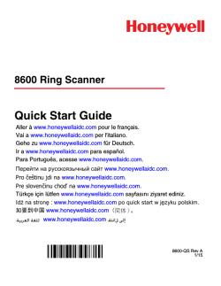
TR-NWT-000030, namely, on-hook data transmission associated with ringing (type I application). Figure 1 shows the physical layer signalling for
²on-hook data transmission with power ringing². The data packet shown is
in ²Multiple Data Message Format² (MDMF).
4
AN9032
T IP /R IN G
F ir s t r in g b u r s t
A
M
e s s a g e
ty p e
M
e s s a g e
le n g th 1
B
C h a n n e l s e iz u r e
C
P a r a m e te r
ty p e
M
a r k
D
P a r a m e te r
le n g th
D a ta
P a r a m e te r
b y te
P a r a m e te r
h e a d e r
E
p a c k e t
M o r e
p a r a m e te r
b y te s
F
S e c o n d
M o r e
p a r a m e te r
m e s s a g e s
G
r in g
b u r s t
C h e c k s u m
P a r a m e te r
b o d y
P a r a m e te r
m e s s a g e
M
e s s a g e
h e a d e r
M
e s s a g e
b o d y
M e s s a g e
Figure 1 Bellcore physical layer signalling (type I application)
The legend to the figure 1 above is described as follows:
1: Message length equals the number of bytes to follow in the message
body, excluding the checksum
A: First 2-second ring burst (nominal 0.2~2.2 seconds)
B: At least 0.5 second silent period between the first ring burst and the
start of data transmission
C: 300 alternating mark and space bits
D: 180 mark bits
E: Time available for sending data (C+D+E=2.9~3.7 seconds)
F: At least 0.2 second before sending the 2nd ring burst
G: Second ring burst
5
AN9032
Actually, the SPCS data interface supports single data message and multiple data message formats. In the single data message format, information
is sent to the CPE as a series of data words specifying message type, message length, message data and error detection information. In the multiple
data message format, information sent to the CPE is similar to the single
message format except the message data field is replaced by a series of parameter messages. Each parameter message consists of data words specifying parameter type, parameter length and parameter data.
For single and multiple data message formats each word shall consist of an
8-bit data byte preceded by a start bit (space) and followed by a stop bit
(mark). The least significant bit of each data byte shall be transmitted
first. The following shows the transmitted word format used by Bellcore.
Stop bit of
word N-1
Start bit of
word N
Bit0~Bit7
Stop bit of
word N
The data transmission must be continuous. If the CO is unable to send
data or is waiting for information to become available during the data
packet, it will insert up to 10 mark bits between data words. The exceptions are between words in a parameter body in MDMF (see Figure 1) and
between message words in SDMF. Since the FSK modulation is used in
both data message formats, the differences between the two formats are
transparent to the HT9032.
Briefly, the CNAM multiple data message format consists of the following:
Channel seizure
signal (1)
Mark signal (2)
Message type word (3)
Message length (4)
Parameter messages
(5)
Check sum word (6)
Field (1) : The channel seizure signal, used for on-hook data transmission
only, is a block of 300 continuous bits of alternating ²0²s and ²1²s. The first
bit to be transmitted is ²0² while the last bit is ²1².
Field (2) : The Mark signal is composed of 180 bits of continuous high.
Field (3) : 1 byte of Message type word.
Field (4) : The Message length is the 1-byte information that specifies the
total number of message data words (for single data message format) or parameter words (multiple data message format) sent to the CPE, excluding
the final checksum.
6
AN9032
Field (5) : Parameter messages can consist of N parameters and each parameter is further divided into three sub-fields in the order shown below:
Parameter Type Word (1 byte): Specifies the interpretation of the sub-field
Parameter Data Words. Possible message types include: time, dialable directory number (DDN), absence of DDN and call qualifier.
Parameter Length Word (1 byte): Equals the number of data bytes contained in the Parameter Data Words sub-field.
Parameter Data Words: Possible data words include: date, time, incoming
call number and reason for absence of DDN. Note all data bytes in this
sub-field are encoded in ASCII format.
Field (6) : 1 byte binary checksum = 2¢s complement of {field (3) + field (4) +
field (5)} mod 256.
mk: mark bits (0~10)
The packet may also be in ²Single Data Message Format² (SDMF). The
caller ID information is transmitted in 1200 baud Bell 202 format FSK between the first and second ring bursts. The transmitted data stream contains a channel seizure signal, a mark interval, and a data packet which
contains the caller ID information. Other information such as the time and
data may also be included in the packet. The channel seizure is 300 alternating marks and spaces. The mark interval is 180 bits.
Message Type
Message
Length
Message Byte
More Message
Bytes
Checksum
Error detection is provided by the use of a checksum word transmitted after the last parameter word of the last parameter message (i. e. it is the
last word of the transmission). It is the two¢s complement of the modular
256 sum of all the preceding words in the data packet (i. e. all message type
and length, all parameter type and length, and all parameter words). The
modular 256 sum is computed by adding the words together and then truncating the sum to the least significart (LS) 8 bits. The CPE should calculate
the modular 256 sum of all words received in the message and add it to the
received checksum. If the LS 8 bits of the result is non-zero, then the received caller ID data is incorrect. In this case an error message should be
displayed because the CO will not retransmit the data.
7
AN9032
The MDMF and SDMF message type values appropriate to CID and
CIDCW are shown in Table 1. Note that both MDMF and SDMF can be
used in CID whereas CIDCW uses MDMF only. Therefore in CID, the
microcontroller software should check for either 80h or 04h to indicate the
beginning of the data packet. In CIDCW, the software should check for 80h
only.
Format
Value
Message Type Meaning
MDMF
80h
MDMF packet header
MDMF
81h
MDMF test sequence packet header
MDMF
82h
Message waiting notification
SDMF
04h
SDMF packet header
SDMF
06h
Message waiting indicator
SDMF
0Bh
Reserved (for Message Desk Information)
Table 1 Bellcore message type word values
In SMDF, the message words contain the information which the CO needs
to transmit to the end user. The information includes only the date, time
and caller number. The following is an example of single data message format which convey the information.
Example of SDMF:
Date: March 21
Time: 2:05 PM
Number: (914) 555-1234 Type
Type
Hex Value
Word order
SDMF header byte
04
1
SDMF packet length byte
12
2
0
30
3
3
33
4
2
32
5
1
31
6
1
31
7
4
34
8
0
30
9
Date
Time
8
AN9032
Type
Number
Hex Value
Word order
5
35
10
9
39
11
1
31
12
4
34
13
5
35
14
5
35
15
5
35
16
1
31
17
2
32
18
3
33
19
4
34
20
53
21
SDMF packet checksum
In MDMF, each message can contain more than date, time, and calling
number, notably, caller¢s name. Thus parameter type words are created to
indicate different parameter data. The parameter type word will be one of
the values in Table 2. The values will depend on what is being transmitted.
01h
Time
02h
Calling Line Identification
03h
Reserved (for Dialable Directory Number (DN))
04h
Reason for Absence of DN
05h
Reserved (for Reason for Redirection)
06h
Call Qualifier
07h
Name
08h
Reason for Absence of Name
0Bh
Message Waiting Notification
Table 2 Bellcore MDMF Parameter Type Word Values for CID and CIDCW
Example of MDMF:
Date and Time: March 21, 2:05 PM
Number: (504) 555-1234
Name: Joe Doe
9
AN9032
Type
Hex Value
Word order
MDMF header byte
80
1
MDMF packet length byte
1F
2
Date & time message header
01
3
Date & time message length
08
4
Date
0
5
5
3
6
6
2
7
7
1
8
8
1
31
9
4
34
10
0
30
11
5
35
12
Calling line identification message
header
02
13
Calling line identification message
length
0A
14
Number
5
35
15
0
30
16
4
34
17
5
35
18
5
35
19
5
35
20
1
31
21
2
32
22
3
33
23
4
34
24
Name message header
07
25
Name message length
07
26
44
27
Time
Name
D
10
AN9032
Type
Hex Value
Word order
O
4F
28
E
45
29
20
30
J
4A
31
O
4F
32
E
45
33
D6
34
MDMF packet checksum
How it works
The principle of CID is relatively simple. Coded signalling information is
sent during the period between the first and second ring. Continuous
phase binary frequency shift keying (FSK) is used for coding. The CID chip
(HT9032) decodes analog information and transforms it into a digital bit
stream which is available at the DOUT pin. A micro-controller extracts
caller information from the digital stream. A CID system has five important functions: line termination during data reception, high voltage isolation, common mode rejection, ring detection and CID data reception. These
functions, with the exception of CID reception, are not built into most CID
devices, so a small amount of external circuitry is required. The receive
data dynamic range of the CID detection circuit is a critical requirement.
On a long loop the signal strength may be very low, but the CID device
must be able to detect it. The transmission level from the terminating C. O.
will be -13.5 dBm +/- 1.0. The expected worst case attenuation through the
loop is expected to be -20 dB. The receiver therefore, should have a sensitivity of approximately -34.5 dBm to handle the worst case installations. Consequently, analog performance as shown by the detect level and the ability
to perform in the presence of noise is very important. The HT9032 for example, has a detect level of -45dBm, specified over the entire temperature
range. The device is also specified to operate at a typical 20dB S/N ratio.
According to the Bellcore specifications, the Customer Premises Equipment (CPE) should terminate the transmission line with the correct impedance while data is being transmitted. The CPE must detect the end of the
first power ring and switch in the termination. The termination is external
to the CID chip and is typically connected with a relay during the period between the first and second ring signals.
11
AN9032
For applications requiring reduced power consumption, a power down
mode is desired. The HT9032 has a power down pin (PDWN), which when
pulled high, forces the device into power down. This is typically done after
receiving a message. In this mode, the CID device ceases to function and
the chip ignore an input signal. Pulling the pin to ground wakes up the
chip and it can then receive the FSK signal and start decoding.
Operation mode
There are three operation modes of Holtek¢s caller ID type I decoders. They
are power-down mode, partial power-up mode, and power-up mode. The
three modes are classified by the following conditions:
Modes
Conditions
Current Consumption
Power-down
PDWN=²1² and ²RTIME=²1²
<1mA
Partial power-up
PDWN=²1² and ²RTIME=²0²
1.9mA typ
Power-up
PDWN=²0²
3.2mA typ
Normally, the PDWN pin and the RTIME pin control the operation mode of
the HT9032. When both pins are HIGH, the decoder is set on the
power-down mode, consuming less than 1mA of supply current. When a
valid power ring arrives, the RTIME will be driven below VT- and the portions of the part involved in the ring signal analysis are enabled. This is
partial power-up mode, consuming approximately 1.9mA typ. Once the
PDWN pin is below VT-, the part will be fully powered up, and ready to receive FSK. During this mode, the device current will increase to approximately 3.2 mA typ. The state of the RTIME pin is nowa ²don¢t care² as far
as the part is concerned. After the FSK message has been received, the
PDWN pin can be allowed to return to VDD and the part will return to the
power-down mode.
Input stage
The input stage is a pre-bandpass filter whose output is then connected to
a precise bandpass filter. The pre-bandpass filter frequency response is analyzed as follows. To obtain a good differential condition, the resistors and
capacitors on the tip and ring path should keep a very good matching
value. The high voltage isolation is attained via resistors R1 and C1. Both
the resistors and the capacitors have a high voltage rating. The high impedance components limit the current and also cause less attenuation. To limit
the high voltage, diodes may be used.
12
AN9032
V
A 1
T o /fro m
T o /fro m
C 1
R 1
lin e
lin e
V
A 2
C 1
R 1
D D
T IP
Y 1
R IN G
Y 2
D D
B a n d p a s s
R 1 : 1 0 k W
C 1 : 0 .0 1 m F
Ring signal detection
The data will be transmitted in the silent period between the first and second power ring before a voice path has been established. The CID type I decoder should first detect a valid ring and then perform the FSK
demodulation. The typical ring detection circuit is depicted in Figure 2.
The power ring signal is first rectified through a bridge circuit and then
sent to a resistor network that attenuates the incoming power ring. The
values of resistors and capacitor given in Figure 2 have been chosen to provide a sufficient voltage at RDET1 to turn on the Schmitt Trigger input
with approximately a 40 Vrms or greater power ring input from tip and
ring. When VT+ of the Schmitt is exceeded, the NMOS on the pin RTIME
will be driven to saturation discharging capacitor on RTIME. The external
RC and internal NMOS on the RTIME constitute a high pass filter. The
value of RC must be chosen to hold the RTIME pin voltage below the VT+
of the RTIME Schmitt trigger between the individual cycles of the power
ring. The values shown will work for ring frequencies at a minimum of 15.3
Hz.
With RDET2 enabled, a portion of the power ring above 1.2 V is fed to the
ring analysis circuit. This circuit is a digital integrator which looks at the
duty cycle of the incoming signal. When the input to RDET2 is above 1.2 V,
the integrator is counting up at an 800 Hz rate. When the input to RDET2
falls below 1.2 V, the integrator counts down at a 400 Hz rate. A ring is qualified when an internal count of 48 is reached. The ring is disqualified when
the count drops to a 32. The number of ring cycles required to qualify the
signal will depend on the amplitude of the voltage presented to RDET2.
The shortest amount of time needed to do the qualification is approximately 60ms. The shortest amount of time required for de-qualification
will be approximately 40 ms. Once the ring signal is qualified, the RDET
13
AN9032
pin will be sent low. This can be used as an interrupt with a Pull-up resistor to an MCU. In this case, once the PDWN pin is below VT- the part will
be fully powered up, and ready to receive FSK. During this mode, the device current will increase to approximately 3.2 mA (typ). The state of the
RTIME pin is now a ²Don¢t care² as far as the part is concerned.
After the FSK message has been received, the PDWN pin can be allowed to
return to VDD and the part will return to the standby mode, consuming
less than 1 mA of supply current. The part is now ready to repeat the same
sequence for the next incoming message.
P D W N
V
D D
2 7 0 k W
P o w e r-u p
L o g ic
R T IM E
0 .2 m F
T o B r id g e
4 7 0 k W
In te rn a l
P o w e r-u p
L o g ic
R D E T 1
R D E T
1 8 k W
R D E T 2
R in g
A n a ly s is
C ir c u it
1 5 k W
1 .2 V
Figure 2 Ring detection circuit
Carrier detection
The carrier detector is a generic level detector together with a digital frequency analysis designed in the decoder. The FSK signals are bandpass filtered on the tip and ring path respectively. Then the difference between
the tip and ring path is fed into a comparator with a detect level. If the FSK
signals are larger than the detect level, the comparator output will be the
1200Hz or 2200Hz logic level signals. However, if the FSK signals are
smaller than the detect level, the comparator will only ouptut a logic one.
The level detector output is then fed into a digital integrator to analyze the
frequency. If both level and frequency are valid, a valid carrier is recognized. For the decoder part to demodulate the FSK signal, a valid carrier
level should be detected first. If no valid carrier is detected, the decoder
will perform no FSK demodulation. The carrier detect sensitivity is -48
dBm. The detect result is the open-drain CDET pin. This can also be used
as an interrupt with a pull-up resistor to an MCU.
14
AN9032
Serial interface
The HT9032 provides two serial data interfaces, namely, DOUT and
DOUTC. Both data output pin presents the output of the demodulator after CDET is low. The difference between DOUT and DOUTC is that
DOUTC does not include the alternate 0 and 1 pattern.
According to the GR-30-CORE, the data is transmitted in serial, binary
and asynchronous method. With asynchronous data, each character is
framed between a start and a stop bit. The first bit transmitted is the start
bit and is always a logic 0. The character code bits are transmitted next beginning with the LSB and continuing through the MSB. The last bit transmitted is the stop bit, which is always a logic 1. A logic 0 is used for the start
bit because an idle condition (no data transmission) is identified by the
transmission of continuous 1¢s or the so called mark signals. Therefore, the
start bit of the first character is identified by a high-to-low transition on
the DOUT pin. After the start bit is detected, the data are clocked into the
MCU with the baud rate of 1200 Hz. If data are transmitted in real time,
the number of idle line 1¢s between each character will vary. During this
idle time, the MCU will simply wait for the occurrence of another start bit
before clocking in the next character.
Problems occur when the MCU samples data from the DOUT pin. The first
is the frequency mismatch between the transmitter and the receiver. The
second is the noise pulse in the data stream. To achieve a robust reception,
the MCU may use a 16 times clock rate higher than the baud rate to sample the DOUT pin. This allows the start-bit verification algorithm to determine if a high-to-low transition on the DOUT pin is actually a valid start
bit and not simply a negative-going noise spike. The figure 3 shows how
this is accomplished. The incoming idle line 1¢s are sampled at a rate 16
times the baud rate. This assures that a high-to-low transition is detected
within 1/16 of a bit time after it occurs. Once a low is detected, the verification algorithm counts off seven clock pulses, then resamples the DOUT
pin. If it is still low, it is assumed that a valid start bit has been detected. If
it has reverted to the high level, it is assumed that the high-to-low transition was simply a noise pulse and is ignored. Once a valid start bit has been
detected and verified, the verification algorithm samples the DOUT once
every 16 clock cycles. Sampling at 16 times the baud rate also established
the sample time to within 1/16 of a bit time from the center of a bit. In addition, this simple algorithm will overcome the frequency mismatch between
the transmission end and receiving end.
15
AN9032
N o is e
p u ls e
S ta r t b it
b 0
tb
8 c lo c k s
tb
8 c lo c k s
D e te c ts h ig h ,
in v a lid
D e te c ts
lo w
D e te c ts
lo w
b 1
1 6 c lo c k s
S a m p le b 0
V a lid s ta r t b it
Figure 3 Start-bit verification
Application Circuits
General application circuit using the HT9032
T IP
0 .2 m F
~
0 .0 1 m F
H T 1 0 5 0
1 0 k W
0 .1 m F
9 V
~
4 7 0 k W
0 .2 m F
R IN G
0 .0 1 m F
T IP
R IN G
1 0 k W
V D D
D O U T C
R D E T 1
R D E T 2
1 8 k W
V
1 5 k W
N C
D D
2 0 k W
2 0 k W
D O U T
C D E T
R D E T
m +
R T IM E
P D W N
V S S
2 7 0 k W
0 .2 m F
0 6 ' !
16
X 1
3 .5 8 M H
X 2
1 0 M W
3 0 p F
3 0 p F
![[参考資料]](http://s2.esdocs.com/store/data/000489216_1-5bbad8a5fad3f11d19ecf30a87a397d9-250x500.png)


© Copyright 2026