
8600 Ring Scanner Quick Start Guide
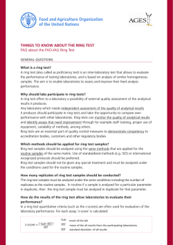
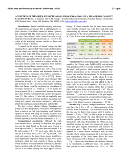
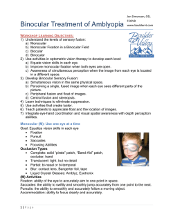
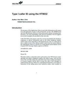
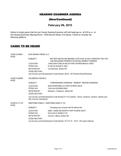
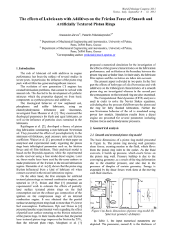
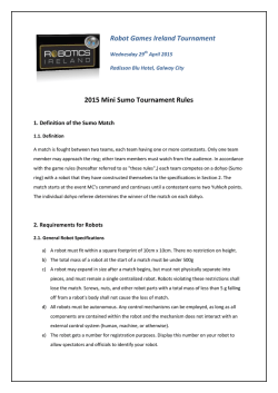
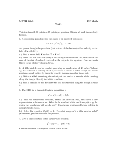
8600 Ring Scanner Quick Start Guide Aller à www.honeywellaidc.com pour le français. Vai a www.honeywellaidc.com per l'italiano. Gehe zu www.honeywellaidc.com für Deutsch. Ir a www.honeywellaidc.com para español. Para Português, acesse www.honeywellaidc.com. Перейти на русскоязычный сайт www.honeywellaidc.com. Pro češtinu jdi na www.honeywellaidc.com. Pre slovenčinu choď na www.honeywellaidc.com. Türkçe için lütfen www.honeywellaidc.com sayfasını ziyaret ediniz. Idź na stronę : www.honeywellaidc.com po quick start w języku polskim. 如要到中国 www.honeywellaidc.com(简体)。 www.honeywellaidc.com 8600-QS Rev A 1/15 Laser Scanner. 1 2 3 4 1. Scan Window 2. Trigger 3. Ring Strap 4. Connector (connect to sled) Laser Imager 1 2 3 4 5 1. Illumination LEDs 2. Scan Window 3. Trigger 4. Ring Strap 5. Connector (connect to sled) Trigger Rotation Scanner head can be rotated 180° Left Hand Right Hand Connect Scanner to Arm Mount Sled Slide the ring scanner cable connector into the bottom of the sled until the connector ring clicks shut. Attach Ring to Finger Step 1 - Slide finger into loosened ring strap Remove Shipping Film The ring cable should not cross under the hand. Step 2 Pull ring strap to secure ring to finger How to Scan a Bar Code Scan Beam Type DANGER Ring Scanner Ring Imager Correct LASER DO NOT STARE DIRECTLY INTO THE LASER BEAM Linear Bar Code 2D Bar Code Incorrect Bar Code Type Wrist Position When Scanning Incorrect Wrist Position Incorrect Wrist Position Correct Wrist Position Remove Ring Strap Module Step 1 - Turn 90°. Step 2 - Press latch down. Step 3 - Remove the ring strap module. Replace Ring Strap Module Step 1 - Connect ring latch with trigger catch. Step 2 - Press together until a click occurs. Step 3 - Turn 90°. Step 4 - Ready to scan. Remove Trigger Step 3 - Lift the trigger up. Step 1 - Remove the ring strap module. Turn the trigger until a black screw is visible. Remove the screw. Step 2 - Turn the trigger 180°. Replace Trigger Step 3 - Insert and tighten the black screw. Step 4 - Replace the ring strap module. Step 1 - Lower the trigger into the ring strap module as shown. Step 2 - Turn the trigger 180°. Technical Assistance Contact information for technical support, product service, and repair can be found at www.honeywellaidc.com. User Documentation For localized versions of this document, and to download the User’s Guide, go to www.honeywellaidc.com. Limited Warranty Refer to www.honeywellaidc.com/warranty_information for your product’s warranty information. Patents For patent information, please refer to www.honeywellaidc.com/patents. Disclaimer Honeywell International Inc. (“HII”) reserves the right to make changes in specifications and other information contained in this document without prior notice, and the reader should in all cases consult HII to determine whether any such changes have been made. The information in this publication does not represent a commitment on the part of HII. HII shall not be liable for technical or editorial errors or omissions contained herein; nor for incidental or consequential damages resulting from the furnishing, performance, or use of this material. This document contains proprietary information that is protected by copyright. All rights are reserved. No part of this document may be photocopied, reproduced, or translated into another language without the prior written consent of HII. 2015 Honeywell International Inc. All rights reserved. Web Address: www.honeywellaidc.com


© Copyright 2026