
1 - Ship Structure Committee
—
SSC-309
A RATIONAL BASIS FOR
THE SELECTION OF ICE
STRENGTHENING
CRITERIA
FOR SHIPS–VOL.
I
Thisdocument has been approved
forpublic
release
and sale;
its
distribution
isunlimited.
SHIP STRUCTURE
1981
COMMllTEE
SHIP STRUCTURE CO+MITTEE
The SHIP STRUCTUREOXLFFITTEEis constituted
to prosecute
a research
progr~
LO ~prove
the hull structures
of Ships and other =rine
structures
by an exten.1.n
.f howledse
pertaining
to design,
materials
and methods of
cc.rmtruction.
skim Clyde T.
Chief,
Office
(Chairman)
Lusk, Jr.
of Merchant Marine
Safety
U. S.
Coast
Guard Headquarters
Hr. J. Gross
Deputy Assistant
Administrator
Crn50ercial
Development
Naxitime
Administration
Mr. P. M. Palemo
Executive
Director
Ship Design & Integration
Directorate
Naval Se. Systems Comand
Mr. J. B. Gresory
Chief,
Research
.5 Dcvelwvmt
of Planning
& Assessment
U.S. Geological
S“mey
m. W. N. Harm..
Vice President
America”
Bweau of
Nr. l%m.ss W. Nle.
Chief Engineering
Officer
Nilitav
Sealift
C-rid
Shipping
LCdr D. B. Anderson,
U.S.
Coast
Guard
for
Staff
(Secretary)
SHIP STRUCTURE SUBCOMMITTEE
The SHIP STRUCTURE SUBCOKrUTTEEacts for tbe Ship Structure
Co.xmittee on technical
matters
by providing
technical
coordination
for the
determination
of goals
and objectives
of tbe program,
and by evaluat i“g and
i“terpreti”g
the results
in terms of structural
design,
construction
and
operation.
u
S
MILTANY SW1
COAST GUARD
IT COF!MAND
Capt. R. L. Brovn
Cdr. J. C. Card
M.. R. S. william.
Cdr. J. A. Sanial
H..
H,.
Ur.
H?.
NAVAL SM
ANZRICAN BUREAUOF SHIPPING
14r.
Mr.
w.
Lcdr
Mr.
SYSTEMS COFS4AND
R. Chlu
J. B. O’Brien
1.1. c. Smdberg
D. W. bhiddor,
T, Nomura (Contracts
Dr.
Hr.
N.
W.
F.
M.
D. Liu
1. L. Stern
U. S . GEOLDCICAL SURVEY
Admi”. )
MARITIMS AIV41N1STRATION
Fir.
Dr.
M..
Mr.
Nbert
At t ermeyer
T. W. Chapman
A. B. Stavovy
D. Stein
D. Hamer
M. tfaclean
Seibold
Tow
Hr. R. G%.ngerelli
Mr. Charles
Smith
INTERNATIONAL SHIP STRUCTURES CONGRESS
Fir.
S.
G. Stiansen
-
Lirnon
Af4SR1CAN IRON & STEEL INSTITUTE
NATIONAL ACADEMYOF SCIENCES
SHIP RESEARCH COFD41TTEE
Mr. A. Dudley Haff - Liaison
U.. R. W. Sunk. - Liaison
sOCIE’11 OF NAVAL ANCHITSCTS 6
NARINE ENGINEERS
N1’. A. B.
StaVOVy - Li8is0n
WELDING RESEARCH COUWCIL
Hr.
K. H. Kwpmcm - Liaison
Hr.
S. H. Sterne
- Liakon
STATE UNIV. OF NEWYORX MARITIME COLLECE
Dr.
W. R. Porter
U. S.
Lcdr
- Liaison
COAST GUARD ACADEMY
R. G. Vorthman
- Liaison
U. S. NAVAL Aw~
U?.
R. Sattacharyya
U. S.
Dr.
- Liaison
NIRCNAW, MAR1fJE ACAnEMY
Chin-Sea
Kin - Liaison
Member
Agencies:
United States CLXW Guard
Naval Sea Systems Comnkmd
Military .5?aIift Command
Maritime Administmtion
United States Geo/ogica/ Survey
American Bwasu of sipping
Address
Correspondence
to:
Secretary, Ship Structure
Committee
Headquarters, (G-MITP
D.C. 20593
U.S.CoastGuard
*
Washington,
#:wJtue
An Interagency
AdvisoryCommittee
Dedicatedto Improvingthe Structure
of Ships
SR-1267
1981
As marine activity in ice covered waters is
expected to increase in the foreseeable future, the design
of ships to meet the varying conditions will have an
expanding role for the naval architect.
The Ship Structure Committee has undertaken a
program to acquire the necessary knowledge to permit a
rational design for vessels which will be operating in
various ice conditions. This first effort in the program
surveyed the various classification societies and government
regulations in order to discern the similarities and
differences of their requirements, and further to recommend
a procedure for selecting appropri ate ice strengthening
criteria. The results of this project are being published
in two volumes. Volume I (SSC-309) contains the analytical
portion of the work and Volume II (SSC-31O) contains the
appendices.
Rear Admiral, U.S. Coast Guard
Chairman, Ship Structure Committee
13)
Technical
ReportDocutnentation
Page
1.
Rep.,,
N.a,
2, Government Acces, ion No.
3, Rec; p:e., s Catalog No.
SSC-309
4. Title
1
I
end S. bt?tl.
5.
A RATIONAL BASIS FOR THE SELECTION OF ICE
STRENGTHENING CRITERIA FOR SHIPS
VOLUME I
Report D.,.
15 February 1981
7
‘“’h”’”)J. L. Coburn, F. W. DeBord, J. B. Montgomery,
9.
Pe,fc.rmin.j
6.
Perto,ming
8.
Per$o,ming Orgon, z@on
A. M. Nawwar, K. E. Dane
O,gon; za,ion N.m,
S.pplemm,.a,y
No. iTRAIS)
or G,.m, No.
DOT-CG-904937-A
Typm O+ Rep.,,
and Per; od Ccm. red
Final Report
20 August 1979 26 May 1980
Nom. .md Address
U.S. “Coast Guard
Office of Merchant Marine Safety
Washington, D.C.
20593
15.
u.,,
I1. Con,,ac,
13.
Spo,m,o,ing Agmcy
Report No.
SR-1267
10.w.rk
and Add,,..
ARCTEC, Incorporated
9104 Red Branch Road
Columbia, Maryland 21045
12.
O,gQ., ZO,im Code
14.
Sponsoring A.aemc. Cod.
R-M
Note,
SHIP STRUCTURE COMMITTEE PROJECT SR 1267
16,
Ab,,r.aci
A major consideration in the development of marine transportation for icecovered waters is the knowledge of the strength required for ship’s hulls. Several
classification societies and various government regulations provide guidelines for
strengthening of ice-transiting ships. However, there are inconsistencies among
these different guidelines, and ships have suffered hul1 damage from ice while
operating in zones for which they were supposedly strengthened adequately. This
report presents the results of a study to develop the basis for rational selection
of ice strengthening criteria for vessels.
Volume I describes sources and differences between ice strengthening
criteria in use by various classification societies, and Government regulations
such as Canadian Arctic Pollution Prevention Regulations, and Swedish-Finnish Winter
Navigation Board Regulations. A comparison of the different criteria is presented
on the basis of a relative weight and relative cost. Effectiveness of the criteria
is evaluated on the basis of statistical ice damage data and on a sample of individual ice damage cases. In addition, a comparison of different materials and fabrication techniques used for ice strengthening is presented. Deficiencies in current
ice strengthening procedures are identified and a rational procedure for selecting
appropriate ice strengthening criteria is presented. In addition, recommendations
for research needed to improve current ice strengthening criteria are described.
Volume II contains the appendicesn~ the report including ma
ice conditions bv month. tabular data. a
a review of methods or
17. Key Word,
18. Di, tribu, ion St.+em.nl
Iassltlcatlon Society Rules
Ice Loads
Documentation is available to the U.S.
Ice-Worthy Ships
Ice Damage
Ice Strengthening
public through the National Technical
Information Service, Springfield,
Hul 1 Strength
Virginia
22161
Icebreaker
Ice Classification
19.
Securi+y C1.aSSif. (oI ?hi, raporl)
Unclassified
FormDOT F 1700.7[8-72)
20.
S.=.ri,y
C1. s,; f. (.{ this ~.ge)
Unclassified
Rcpmd.ction
of completed
. . .
‘Lt-L
21. N=,. of Page,
22,
Price
152
page
authorized
-
:
l“ ‘z ‘;““z“ “ “ “ “ “ “ “ “
0’6 ‘ L ‘
s ‘ cz ‘“’
‘ MlI1111
I INII1111
‘ 11111111
I 11111111
I
11111111
111111111
;11 I 1111111111111111
II 1111111111111111
II 11111111
I 1111111111111111
II 1111111111111111
II 11111111
I 111111111111
II Ill
I 1111
IM 111111111
I11111111
1111
1[11
11111111
g
v
u
=
,,,,,,OO!!!!0,,000!0!4!!,!!!1!!1,!!!!,1!!,,,,,,,,,,,,,,!,,,,,,,,,,!!,,,,
1[1 1[1 Ill Ill Ill Ill 1]1 Ill Ill Ill Ill Ill 1[1 Ill Ill Ill Ill [Ii
9
1
7
1
$
4
3
2
1
,“*
s
L
—
CONTENTS
VOLUME I
1.
Page
INTRODUCTION
. . . . . . . . . . . . . . . . . . . . . . . . . . . . ..1-1
l.lObjective
. . . . . . . . . . . .. . . . . . . . . . . . . .
. ..1-1
1.2 Background
. . . . . . . . . . . . . . . . . . . . . . . . . . . .1-1
1.3 Approach . . . . . . . . . . . . . . . . . . . . . . . . . . . . .1-3
2.
PROBLEP 1DEFINITION.
2.1
2.2
2.3
2.4
3.
4.
6.
7.
ICE STRENGTHENING
.
.
.
.
.
.
.
.
.
.
.
.
.
.
.
.
.
.
.
.
.
.
.
.
.
.
.
.
.
.
.
.
.
.
.
.
.
.
.
.
.
.
.
.
.
.
.
.
.
.
.
.
.
.
.
.
.2-1
.2-2
. 2-12
.2-14
. . . . . . . . . . . . . . . . . . ..
CRITERIA
Ships
. .
. . . . . ,
. . . . . .
. . . . . .
.
.
.
.
.
.
.
.
.
.
.
.
.
.
.
.
.
.
.
.
3-1
OF ICE-CLASSED SHIPS
.
.
.
.
4-1
.
.
.
.
4-1
4-9
4-12
4-13
. . . . . . . . . . . . . . . . . . 5-1
General Description of Existing Criteria
. . . . . . . . . . .
Methods for Selecting the Level of Ice Strengthening
. . . . .
Load Criteria, Rationale, and Structural Design Methods . . . .
Resulting Scantl ings for Three Representative Ships . . . . . .
Analysis of the Load-Carrying Capabi 1ity of Resulting Scantlings
Analysis of Equivalence Between Certain Criteria
. . . . . . .
Comparison of Relative Steel Heights and Fabrication Costs
. .
.
.
.
.
.
.
.
.
.
. .
. .
5-1
5-1
5-4
5-19
5-27
5-33
5-36
. . . . . . . . . . . . . . . . . . . .6-1
Specific Ice Damge
. . . . . . . . . . . . . . . . . . . . . . ..6-1
General and Fleet Experience with Ice-Classed Ships . . . . . . . . 6-1
CRITIQUE OF CURRENT CRITERIA
7.1
7.2
7.3
7.4
.
.
.
.
. . . . . . . . . . . . . . . . . . . . . . . . . . . . . ..
EXPERIENCE
6.1
6.2
. . . . . . . . .
.
.
.
.
Material Requirements for Ice Strengthened
Currently Available Steels
. . . . . . .
Existing Criteria for Material Selection
Requirements for Additional .Information .
EXISTING
5.1
5.2
5.3
5.4
5.5
5.6
5.7
. . . . .
. . . . .
Response
. . . . .
Introduction
. . . . . . . . . . . . . . . . . . . . . . . . ...3-1
Govern ing Ice Conditions
. . . . . . . . . . . . . . . . . . ...3-1
Sources of Data and Analysis Procedures . . . . . . . . . . . . . . 3-4
MATERIALS
4.1
4.2
4.3
4.4
5.
Introduction
~ . . . .
DefinitionofLoad
. .
Definition of Structural
Reliability . . . . . .
ENVIRONMENT.
3.1
3.2
3.3
. . . . . . . . . . . . . . . . . . . . . . . . . .2-I
. . . . . . . . . . .. . . . . . . . ...7-1
General Deficiencies..
. . . . . . . . . . . .
Assumed Distribution of Load for Frame Oesign . .
Factors and Method Used to Determine Design Load
Structural Analysis Methods and Response Criteria
1)
.
.
.
.
.
.
.
.
.
.
.
.
.
.
.
.
.
.
.
.
.
.
.
.
...7-1
. . .7-2
. . .7-6
. . .7-6
—-.
. ..
CONTENTS
(Continued)
.
8.
PROPOSED RATIONAL BASIS FOR SELECTING
8.1
8.2
8.3
8.4
8.5
9.
Material s........
Reliability . . . .
Loads.
. . . . . .
Response Criteria.
Summary of Proposed
RECOMMENDATIONS-NEEDED
.
. . . .
. . . .
. . . .
Approach
.
.
.
.
.
.
.
.
.
Page
ICE STRENGTHENING
.
.
.
.
.
.
.
.
.
.
.
.
.
.
.
.
.
.
.
.
.
.
.
.
.
RESEARCH AND DEVELOPMENT
9.1
9.2
9.3
9.4
R&D Program Summary . . . . .
Full -Scale Tests
. . . . . .
Refine the Rational Approach
Incorporate Response Criteria
in Section 8 ...,.....
9.51ce
Interaction . . . . . . .
9.6 Generalize the Analytic Model
.
.
.
.
.
.
.
.
.
.
.
.
.
.
.
.
.
.
.
.
CRITERIA
.
.
.
.
.
.
.
.
.
.
.
.
.
.
.
.
.
.
.
.
.
.
.
.
.
. . . . 8-1
.
.
.
.
.
...8-1
. ..8-1
. . .8-4
. . .8-5
. . . 8-8
. . . . . . . . . . . . 9-1
. . . . . . . . . . . . .
. . . . . . . . . . . . .
. . . . . . . . . . . . .
into the Approach Proposed
. . . . . . . . . . . .
. . . . . . . . . . . . .
of Ship-Ice Interaction .
. . . . ..9-1
. . ...
.9-1
. . . . . . 9-3
. . . . ..9-3
. . . ...9-4
. . . . . . 9-5
. . . . . . . . . . . . . . . . . . . . . . . . . .. . .
10.
BIBLIOGRAPHY
11.
APPENDIX - Ice Terms Arranged in Alphabetical
Order.
.10-1”
. . . . . . . . . . 11-1
VOLUME II
A - Maximum and Average Ice Conditions by Month . . . . . . . . . . . . .
A-1
B - Tabular Data . . . . . . . . . . . . . . . . . . . . . . . . . . . ..
B-1
C-
c-1
Review of Methods for Damage
. . . . . . . . . . . . . . . . . . ..
LIST OF FIGURES
Number
.
Title
~
1.1
Projected Offshore Alaska Commercial
2.1
General Effect of Strain-Rate
2.2
Bore-Hole
2.3
Effect of Ice Thickness and Failure Mode on Maximum Ice
Impact Force
. . . . . . . . . . . . . . . . . . . . . . . . . ..
Jack Test Results
on Ice Strength
. . . . . . . . . 1-3
. . . . . . . . . . . 2-3
. . . . . . . . . . . . . . . . . . . . 2-5
2.4
Effect of Crushing Strength
2.5
Effect of Impact Speed on Maximum
3..1
Maximum
Ice Conditions,
Development
in Crushing-Bending
April
Ice Load
Failure Mode
2-13
. . . 2-13
. . . . . . . . . . . . 2-13
. . .“. . . . . . . . . . . . . . . . 3-3
LIST OF FIGURES (Continued)
Number
F’aQg
~
4.1
Summary of DT Test Performance of the ABS Grade A Plates
. . . . . 4-2
4.2
Summary of DT ‘1
~st Performance of the A8S Grade 8 Plates
. . . . . 4-2
4.3
Summary of DT Test Performance of Heat Treated (Normalized A8S
Grade D Plates and of One As-Rolled A8S Grade D Plate . . . . . . . 4-3
4.4
Summary of DT Test Performance of A8S Grade E Plates
4.5
Summary of DT Test Performance of ASS Grade CS Plates . . . . . . . 4-4
4.6
5/8” Parent DT, Press-Notch, AH-32 (Heat 2) . . . . . . . . . . . . 4-4
4.7
Charpy V-Notch Impact Test Curves for A8S-DH Steel
4.8
EH-32 (Heat 3), 5/8” Parent DT, Press-Notch
4.9
DT and CVN Test Results for 537A Steel
4.10
DT and CVN Test Results for A537B Steel . . . . . . . . . . . . . . 4-6
4.11
OT and CVN Test Results for A537B Steel . . . . . . . . . . . . . . 4-7
4.12
A678-C
4.13
DT Test Results for ASTM A-71O Grade A Steel Plates . . . . . . . . 4-8
5.1
Arctic Pollution
5.2
Canadian ASPPR Hul 1 Areas for Ice Strengthening
5.3
ASPPR Rule Ice Pressure vs. Arctic Class of Ship
. . . . . . . . . 5-lo
5.4
Example of Damage Analysis Conducted
. . . . . . . . . 5-13
5.5
Comparison of Framing Design Ice Pressures Specified by Johansson
with Those Specified by the Finnish-Swedish Ice Class Rules . . . . 5-13
5.6
POLAR Class Icebelt Configuration
5.7
Oesign Ice ,Loads for Icebreakers Based on USCG Experience
!5.8
Regression of Full-Scale Ice Load Data From the MACKINAW and
LEON FRAZER Tests . . . . . . . . . . . . . . . . . . . . . . . ..
. ,. . . . . . 4-3
. . . . . . . . 4-5
. . . . . . . . . . . . 4-5
. . . . . . . . . . . . . . 4-6
(}{eat 7), 5/8” Parent DT, Press-Notch
. . . . . . . . . . . 4-7
Prevention Control Zones . . . . . . . . . . . . . 5-5
Structural
Configuration
. . . . . . . . . . 5-9
by Johansson
Showing Design Pressures
.
.
.
5-18
. . . . . 5-18
5.9
Assumed
5.10
Comparison of Bow Plating Design Pressures for Three
Representati re ships
. . . . . . . . . . . . . . . . . . . . . ..
vii
of Three Representative
.
Ships
5-20
. . 5-21
5-21
—
LIST OF FIGURES (Continued)
Number
Title
~
5.11
Comparison of Bow Transverse Frame Design Pressures for Three
Representative Ships
. . . . . . . . . . . . . . . . . . . . . . . 5-25
5.12
Variation in Plating Design Pressure with Hull Area for
POLAR STAR
. . . . . . . . . . . . . . . . . . . . . . . . . ...5-26
5.13
Load-Carrying Capabi 1ity of PDLAR STAR Bow Structure for Various
Ice Strengthening Criteria
. . . . . . . . . . . . . . . . . . . . 5-30
5.14
Load-Carrying Capability of MV ARCTIC Bow Structure for Various
Ice Strengthening Criteria
. . . . . . . . . . . . . . . . . . . . 5-31
5.15
Load-Carrying Capability of Arctic Tanker Bow Structure for
Various Ice Strengthening Criteria
. . . . . . . . . . . . . . . . 5-32
5.16
Percentage Increases in Steel Weights Above ABS Al for Ice
Strengthened Midbody Panels . . . . . . . . . . . . . . . . . . . . 5-40
6.1
MV ARCTIC
6.2
Structural Differences Between the EDldIN H. GOTT and the
BELLE RIVER . . . . . . . . . . . . . . . . . . . . . . . . . ...6-6
6.3
Predicted
12inchand
~.4
Relative Frequency of Ice Damage to Ships with Various Ice
Classing
. . . . . . . . . . . . . . . . . . . . . . . . . . . . . 6-9
6.5
Relative Frequency of Ice Damage for Different Types of Ships . . . 6-9
6.6
Histogram Showing Distribution of Damage Incidents According to
Ship Tonnage
. . . . . . . . . . . . . . . . . . . . . . . . . . . 6-10
6.7
Distribution
7.l(a)
General Description
7.l(b)
Form of Load Distribution
7.2
Comparison of Section Modulus for MV ARCTIC as Computed by
Eqn. 7.2 and in Accordance with Ref. [C-11] . . . . . . . . .
‘7.3
Ice Damage, October 1978
. . . . . . . . . . . . . . . . 6-2
Ice Impact Forces on Hull vs. Distance from F.P. for
6inch Level Ice..
. . . . . . . . . . . . . . . . . 6-7
of Damage Incidents Per Time of the Year . . . . . . . 6-11
of Load Distribution
in Johansson’s
Used by Johansson
Example of Damage Analysis Conducted
Proposed Triaxial
8.2
POLAR STAR Hull (Strain Gage) Response,
9.1
Recommended
. . 7-3
in Final Form . . .
by Johansson
8.1
Method
.
.
. 7-3
.
. 7-5
from Ref. B-16] . 7-7
Strength Factor . . . . . . . . . . . . . . . . . 8-3
Schedule for R&b Program
1976
. . . . . . . . . . . 8-6
. . . . . . . . . . . . . . . 9-6
‘
...
v%%%
-
. —
LIST OF TABLES
Number
~
Title
2.1
Selected Class for Ice Load Predictions
2.2
Model Hull Oata Sheet -MV
2.3
Comparison of Characteristics of NV ARCTIC as Bui 1t and
Scaled-Up Ship
. . . . . . . . . . . . . . . . . . . . . . ...-2-9
2.4
Results
5.1
Listing of Current Ice Strengthening
5.2
Classification Society Regulations Oeemed Equivalent to
Canadian ASPPR Types
. . . . . . . . . . . . . . . . . . . . . . . 5-3
5.3
Classification Society Ice Classes Identical or Equivalent to
Finnish-Swedish Regulations . . . . . . . . . . . . . . . . . . . . 5-3
5.4
Canadian Restrictions to Navigation by Control Zone and
Time of Year
. . . . . . . . . . . . . . . . . . . . . . . . . ..
ARCTIC
. . . . . . . . . . . . . . 2-7
. . . . . . . . . . . . . . ...2-8
. . . . . . . . . .. . . . . . . . . . . . . . . . . . . ..
Criteria
2-11
. . . . . . . . . . - 5-2
5-6
5.5
Ice Strengthening Criteria Which Specify Scantlings by
Increasing Normal Rule Scantlings . . . . . . . . . . . . . . . . . 5-8
5.6
Ice Pressures Used by the Canadian Arctic Shipping Pollution
Prevention Regulations
. . . . . . . . . . . . . . . . . . . ...5-10
5.7
Principal Characteristics
5.8
American 8ureau of Shipping Scantl ings for Three
Representative Ships
. . . . . . . . . . . . . . . . . . . . . . . 5-22
5.9
Ice Strengthened Bow Plating Thickness for Three
Representati re ships
. . . . . . . . . . . . . . . . . . . . . ..
5-28
Ice Strengthened 80W Transverse Frame Section Modul i for Three
Representati re ships
. . . . . . . . . . . . . . . . . . . . . ..
5-29
5.10
of Three Representative
Ships . . . . . . 5-20
5.11
Typical
5.12
Equivalent Design Pressures
6.1
Powering and 80W Structure Specifications for Ten Great Lakes
Vessel s . . . . . . . . . . . . . . . . . . . . . . . . . . . . . . 6-4
6.2
Selected Oamage Incidents for Ice Classed Ships in Canadian
Waters (1970-1978 )........
. . . . . . . . . . . . . ...6-13
Ice Class Cargo Ship Oata . . . . . . . . . . . . . . . . . 5-37
in Various Criteria
‘h
. . . . . . . . . . 5-38
—
LIST OF TABLES (Continued)
Number
—m
@
7.1
Ice Pressure, Bow Area.....
. . . . . . . . . . . . . . . . . 7-2
7.2,
Summary of Differences
8.1
Uniaxial Crushing Strength
9.1
R&D Programs to Improve Ice Strengthening Criteria
Breakdown by Objectives . . . . . . . . . . . . . . . . . . . . ..
Among Ice Strengthening
Criteria
. . . . . . 7-8
. . . . . . . . . . . . . . . . . . . . 8-3
.
9-1
1.
1.1
INTRODUCTION
Objective
The principal objective of the work described by this report is to develop
a basis for the rational selection of ice strengthening criteria for vessels.
An important secondary objective is to identify areas requiring research and
development.
The role and nature of the “rational basis” for the selection of ice
It is understood that it is not the
strengthening are described as follows:
position of this project team, nor any other R&D team or investigator, to
specify that a ship for this ice service must have plating so many inches
Rather, the results should
thick, or scantl ings of thus and so dimensions.
be cast in a format that presents to the regulatory body, the classification
society, and the owner, a method to associate a level of confidence with the
selection of certain plating and scantl ings for a given ice service.
In this
format, the researcher presents his results, independent of the important, but
separate, consideration of risks. The weighing of risks is left to the various
sovereign governments, the underwriters, and the owners.
1.2
Background
The need to address the subject of a rational basis for ice strengthenthe world-wide increase of marine
ing criteria stems from two conditions:
activity in ice-covered areas, particularly, but not restricted to, the Arctic,
and the rather wide disparities among the existing criteria for ice strengthening ships. The existing criteria and their differences are analyzed in detail
in this report. Marine activity in the Arctic and subarctic areas with sea
ice has been spurred by the worl d-wide petroleum shortage and the presence
For example, the Prudhoe Bay oil field
of major proven and probable reserves.
is the largest outside of Saudi Arabia.
At the current production rate of 1.2
mi 11ion barrels per day, Prudhoe Bay production ranks near the middle of the
OPEC nations.
The recent (late 1979) lease sale of offshore tracts in the Beaufort Sea
is an important portent that the technology to produce and deliver petroleum
from offshore areas of the Arctic will be developed.
The U.S. Bering Sea may
prove to be as fruitful, if not more difficult, than the North Sea. The U.S.
Department of the Interior, Bureau of Land Management, has published lease sale
schedules which are summarized in Figure 1.1. Although subject to revision,
there is 1ittle doubt that exploration and production wil 1 proceed.
The U.S. and Canadian Arctic are not the only ice-covered areas which
are being developed.
The Russians and Japanese are proceeding with plans to
develop petroleum reserves offshore Sakhal in Island and the Chinese are expanding operations in Po Hai Bay with Japanese help. Both of these areas are subjected to heavy seasonal sea ice conditions.
In the Great Lakes, a major effort has been undertaken by both government
and industry to achieve year-round transportation in an area where eight months
a year was previously the rule. To expand the eight month operating season, a
variety of systems had to be developed to permit commercial vessel operation
through the ice bottleneck portions of the Great Lakes. Progress in this area
1-1
—
172
~
I !
,,
K221.
90
@owe.Gmk Inlet
@B-bd3.rs.
QG4C d Af=h
@KOdi& Shelf
@NoXon
,,
.,
?.9 km m:
P—
.
—
~
E
./-
33asJn
!.E
@Chuk&iSe.
L
7 Zhemchug Z3asIh
@se &wy. Be.+.
@8F1.tiI Zkzy
@NwYwi.
.!.
Bud.
@w2.bu.
SoLid
@4.Ld/u.
shelf
@5tA-fo?Yha4%$/in
L = Lease
Figure
1.1
5./c
Projected
L
=.&/7/Ora
?,0/7
p
= Fh7ducfion
Offshore Alaska Commercial Development
1-2
—
was initially slow but within a period of seven years, year-round operation has
been achieved on some routes. Today, both industry and government real ize the
benefits of year-round shipping within the Great Lakes and new ship construction
ref 1ects the capabi 1ity for year-round transportation.
The focus of this report is on the required hull strength for ships to be
operated in ice. The classification societies provide guidelines for the strengthIn order to implement these guidelines, however,
ening of ice-transiting ships.
the ship owner must select the class of ice strengthening for a vessel. The
information and guidance upon which to base such a selection is,in many cases,
It is not at all clear how a particular trade route (area and month)
inadequate.
is related to medium, severe, or extreme ice conditions as described in some of
the classification rules. Nor has any relationship relating ice thickness and
type with an ice class been shown.
The Canadian Government, much to its credit, did recognize the dependence
of appropriate ice strengthening on ice conditions.
The CANADIAN ARCTIC SHIPPING
POLLUTION
PREVENTION REGULATIONS (CASPP17)specify degree of ice strengthening
in terms of geographic location and season (monthly). An examination of the
Canadian ASPPR ice strengthening requirements shows that the ASPPR requi res
greater and, in some cases, much greater ice strengthening than those required
by classification societies in the design of U.S. Coast Guard icebreakers.
Nevertheless, recently two Canadian ships, one an icebreaker and the other a
commercial icebreaking ship, suffered extensive hull damage while operating in
an ice zone specified by the CASPPR.
These and other deficiencies in selecting adequate ice strengthening
criteria, combined with the recognition of the near-term growth in the number
of ice-transiting vessels, led the Ship Structure Comnittee to address the need
to develop a basis for the rational selection of ice strengthening criteria.
1.3
Approach
In the next section, the problems of ice strengthening wi 11 be discussed
in detai 1 and defined in meaningful terms. Subsequent sections focus on the key
variable over which there is no control and, as will be shown, about which 1ittle
is known--the environment; material properties are described and criteria proposed.
It appears that the importance of materials is fully recognized and that
it is reasonably within the state-of-the-art to describe adequate materials
Existing ice strengthening criteria are compared in detail , including
criteria.
load-carrying capacity, weight, and cost for three specific applications.
Certain general and specific shortcomings of various criteria are identified.
Specific and general experience with operations of ice strengthened ships in ice
Some statistical sumnaries are presented and an analysis of a
is examined.
dramatic ice strengthening failure is included.
Ouring this project, certain elements, which are essential to a rational
approach to ice strengthening, became obvious. These key elements are combined
into a proposed framework for rational ice strengthening.
The framework, or
approa~h, to ice strengthening criteria is proposed although there are many
specific details which are not now known. These areas of the unknown become
the basis for the recommended R&D program.
1-3
L——.
,——
2.
PROBLEM DEFINITION
2.1
Introduction
To effectively define the problem, the objective of the program, as stated
in Section l.must be broken down into elements and defined in terms which are
Accordingly, the general objective, to develop a
meaningful to the designer.
rational basis for ice-strengthening shiPS, was broken down following the Ship
Structure Commi ttee’s Long Range Goals:
.
.
o
.
.
.
.
Plannin~ and R&O
Load Cr~teria
Response Criteria
Materials Criteria
Fabrication Criteria
Reliability
Design
Load criteria, response criteria, and reliability are discussed in detail in the
fol lowing subsections.
Section 4 presents the materials and fabrication
criteria.
Planning and R&O are discussed in Section 9. The design element was
not treated in this study.
2.1.1
Load Criteria
Load criteria must somehow be related to ice properties, ice conditions,
ice features, the interaction between the ship and the ice, and, ultimately,
to the fundamental design parameters of trade route (including season) and
acceptable level of risk. The specification of the load must be compatible with
the analytic techniques to be applied in evaluating the response element of the
ice strengthening criteria.
2.1.2
Response Criteria
Response criteria must include consideration of the methods for analyzing
the structure’s response to loads, as wel 1 as the index of satisfactory structural
performance.
Consideration of a particular analytical tool , e.g. finite-element
analysis or plastic analysis, is not intended to preempt alternative analytical
methods.
One or more methods must be considered in detail to ensure that the
nature of the load definition is complete or adequate for analysis, even though
alternative methods are accepted as val id.
2.1.3
Naterials and Fabrication Criteria
Material properties and fabrication techniques wil 1 be considered to~ether. Material pro~erty specifications should be derived from environmental
~onditions and load c;ite;ia’. Since this studv is limited to normal shiobuildina
practices, the only aspects of structural fabr~cation to be considered are those
special fabrication requirements or restrictions imposed by the materials themselves.
2.1.4
Reliability
,The state of knowledge of icc-imposed loads does not warrant a quantitative
approach to structural reliability.
However, the factors which must be considered
are identified and a subjective approach to factors-of-safety is proposed.
—
2.2
Definition of Load
The load should be defined in terms of an intensity (pressure, psi),
a description of that intensity over the hul 1 surface (x, y extent, and variation
with location); the rate of application or generation of the load, and the
intensity-frequency distribution expected over the ship’s 1ife. It has been
shown [E-14] that the rate of application is not significant in the res Ponse of
the structure of the ship, but it may be an important variable in determining the
load which the crushing ice can impose on the ship.
An implicit element of any criterion is that the ice will fail , or the
load wil 1 be relieved by other mechanisms or motion, before the structure fai 1s.
Therefore, it is necessary to study the load-carrying ability of the different
kinds of ice under consideration.
2.2.1
Ice Properties
Michel [A-25] provides an excel lent compilation of research data and interpretation pertinent to ice properties.
Some of the well-known properties are:
. Ice is a polycrystal line material found in nature with totally random
When a
crystal orientation and with varying degrees of preferred orientation.
strong preferred orientation exists, general ly designated in terms of the “taxis”, the ice is anistropic, being stronger in the direction parallel to the
c-axis orientation.
. Important mechanical properties of ice are strongly temperature dependent. As a result, ice strength varies with temperature through the ice sheet,
decreasing from the colder air temperatures to the warmer water temperatures.
. Ice strength is dependent on the salinity of the ice. A consequence of
this is that fresh water ice is generally stronger than sea ice and old, multiyear ice, which loses salinity with warming and refreezing, is stronger than newly
frozen sea ice.
. Ice strength is strain-rate dependent, exhibiting almost perfect plastic
properties at strain rates in the creep (10-” see-]) range. The transition to
elastic behavior occurs around 10-2 see-l. The quantity of pertinent data is
almost inversely proportional to the strain rate, much of the research having
focused on the plastic-creep behavior of glaciers. There are data which indicate
that ice behaves elastically for some range of strain rates greater than 10-2
see-’. However, there are virtually no data available in the open literature at
strain rates which may be characteristic of ship-ice interactions.
Some proprietary research has been performed which indicates that entirely different
fail ure modes are induced at very high rates of loading.
Figure 2.1 is a combination of some generalized information from Michel [A-25] and a qualitative
representation of the proprietary research results.
. Ice strength, as in the case of many materials, is dependent on the
method of measuring it. Of particular importance is the dependence of crushing
strength on confining pressure. Uniaxial crushing strength ranges from 100 psi to
500 psi depending on direction, temperature, salinity, and strain rate. The
maximum triaxial crushing strength may be several times the uniaxial. Virtually
‘
al 1 of the data available are for uniaxial tests. Some research has been conducted on the triaxial strength of ice but the results of these efforts are
proprietary.
2-2
~
_—
—-...
—
Ice
Stmn@h
4
f
I
,.-6
I
,Q-5
i
/0-3
1
/0+
2
Figure 2.1
1
M-z
1
,.-1
I
1
I
10
(+ec-’)
General Ef feet of Strain Rate on Ice S’mengtil
2-3
L.
In terms of ship-ice interaction, neither triaxial nor uniaxial test
results are directly applicable.
As the ice is crushed by the ship, the crushing
interface of the ice and the fai lure zone immediately behind it are confined to
some degree by the surrounding ice. This sel f-confinement does increase the
crushing strength through the triaxial mechanism, although there are no
quantitative data which can be used directly. “Bore-hole” tests [A-19] o~h~se~~ushir
strength bring the appropriate mechanisms into play and are pertinent.
an experiment in which a hydraulic CY1 inder jack is placed horizontally in a
vertical hole in the ice. A pressure-time (or displacement) record is made as
the jack is forced against the walls of the hole. An example is shown in
Figure 2.2. The peak stress imposed can be calculated from the pressure and
appropriate areas. Although there is no known exact relationship between this
stress and those developed in a ship-ice interaction, it is felt that this method
provides a “handle” for accounting for the self-confined, partial triaxial
strength of ice. Unfortunately, there are no bore-hole test results available in
the open 1iterature.
Experience has shown that, as ice sample size increases from laboratory
scale to field test scale. ice strenath aoDears to decrease. This is due to
the inclusion of more natural defect: in the test specimen. To date, no real lY
large (several meters) scale. tests of ice properties have been made available to
the public. A proprietary program for such tests is currently entering a second year
2.2.2
Hull-Ice Interaction
The real phenomena involved as a ship transits ice-covered waters are
dynamic, unsteady, and very complex. The resistive components of the hul l-ice
interaction have been studied from, purely theoretical, purely empirical, and
combined semi-empirical viewpoints.
The results of several years of research
and analysis have led to a state-of-the-art in predicting the resistance of ships
in ice roughly equivalent to that achievable for open water in Froude’s day.
The state of the art in predicting structural forces acting on a ship’s hull in
ice is much more rudimentary.
This is due primarily to the limited full-scale
data which have been CO1 lected.
One such set of full -scale structural data comes from the MACKINAW trials
[B-7 ]. It was shown that the ice load varies both in space (location on the
hull ) and time. It is neither a simple concentrated load nor a purely
distributed load. Edwards, et al [ B-7] describe the sPatial and temPoral
variation of the ice loads. Since the observed parameter was structural response
(straim gage arrays~ the description of the actual load is at best ambiguous.
No simple generalization was found which described the load.
A purely analytical mathematical model has been developed [B-26,B-3B].
This is essentially a rigid-body mechanics treatment of the collision of a shiu
with ice. The resulting force is calculated by a computer program in a timestep sequence. The main factors considered are:
. Elastic and nonelastic response of ice in crushing and
bending.
. Rigid-body motions
of the ship and, in the case of
discrete ice floes, the ice.
. The hydrodynamics effects, added mass, and damping.
2-4
1
Nax
0u5~i~
———
——.
(..&deV
5trwn@7
54P
-
—.—
—
Gonfi’ed
Cbruii+ions
P(6)
t
Figure 2.2
or dispkernen
t
Bore-Hole Jack Test Results
2-5
L.
—
The shape, in terms of direction cosines, of the ship’s
hull .
. Speed and size of the ship.
. Thickness, size of ice floes, and properties of ice.
The aoDroach is ex~lained in detail by Major, et al [B-261. ln that PaPer,
the results o+ exercising” the mathematical model are compared with full-scale
Interpretation of the MACKINAW data is so
results of the MACKINAN trials.
clifficult that al 1 that can be said about the comparison is that the two methods
are in agreement in the order of magnitude and in the most general of terms.
Nevertheless, the analytical method should accurately reflect the dependence of
ice induced forces on the key parameters.
2.2.2.1 Application of Analytical Hodel of Hull-Ice Interaction - This
section presents the results of the analysis of selected cases of impact between ship
Its main objective is to study the effect of variation
and various ice features.
of key parameters on the ice load. It is not intended to validate the prediction
program nor to reproduce ice conditions which can inflict damage on the selected ship.
In fact, the MV ARCTIC, a 28,000 D!dT bulk carrier, was chosen for this work.
A total of 18 runs were specified for the fol lowing conditions:
Level Ice:
Discrete Floes:
Bergy Bits:
Crushing Strength:
Speed:
h=l,3,
and6ft
D = 50, 200, and 500 ft
h = 10 and 20 ft
oc = 300, 1000, and 2000 psi
u = 6 and 12 kts
where
h = ice thickness
D = diameter
All runs were made using the MV ARCTIC as built except for three cases. where
a scaled-up MV ARCTIC (A = 150,000 short tons) was used. Table 2.1 provides
details of the selected runs.
for the
2.2.2.2
Ship Characteristics and Input Data - The major characteristics
MV ARCTIC (as built) are given in Table 2.2.
To develop the characteristics for a scaled-up ship, the deadweight
was used as a basis for the scaling factor:
~ =
tonnage
p]
DWT (Scaled-Up Shi )
DWT (As 8uilt
[
1/3
For a scaled-up MV ARCTIC of 100,000 tons OWT, the seal inq factor is 1.527 and the
displacement of the large ship equals 134,206 L. tons (13G,360 tonnes) as compared
to 37,704 L.tons (38,309 tonnes) of the as-built ship.
Applying this seal ing factor to the as-built ship resulted in ship
characteristics for the scaled-up vessel .. Table 2.3 presents a summary of data
2-6
-
TABLE 2.1
SELECTED CASES FOR ICE LOAD PREDICTIONS
SHIP
MV ARCTIC
(as built)
(ft)
(k;ots)
(ft)
ICE
CRUSHING
STRENGTH,
%
(PS1 )
1
1.0
6.0
.
300
2
3.0
6.0
.
300
3
3.0
12.0
m
300
4
3.0
6.0
.
1,000
5
3.0
6.0
.
2,000
6
6.0
6.0
.
300
7
3.0
12.0
50
300
8
3.0
12.0
200
300
9
3.0
12.0
500
300
10
3.0
12.0
200
1,000
11
3.0
12.0
200
2,000
12
3.0
6.0
200
300
13
6.0
12.0
200
300
14
20.0
12.0
50
1,000
15
10.0
12.0
50
1,000
Level Ice
~i~crete Floes
16
6.0
6.0
.
300
17
3.0
12.0
200
300
Bergy Bits
18
20.0
12.0
50
1,000
ICE TYPE
Level ice
Discrete Floes
Bergy Bits
MV ARCTIC
(A = 134,206 LT)
c~:E
2-7
ICE
THIC~NESS, V;![;!;Y, DI~~;ER,
TABLE 2.2
DESIGNATIOii
;ERIAL #
1
MODEL HULL DATA SHEET
—
.—
‘ESSEL NAME
SCALE
MV ARCTIC
(14,770 HP)
(27,650 L ton DWT)
&
FS
IULL FORM
*DIMENSIONAL
PARAMETERS
=
0.759
Cbf =
0.798
Cb
L = 645.33 ft
~ =
75.00
ft
H = 50.00
ft
‘
0.764
=
0.876
‘P
2’ =
36..00
v=
1,317,150 ft’
& =
37,764 L ton
Cw
Cwf =
cm
=
0.991
Y.
=
30”
65
=
o“
pARA~~~TERs
**NONDIMENSIONAL
L/B =
8.60
BIT =
2.084
GEOMETRY-FRICTION
PO =
1.650
V2 =
2.620
FRICTION
COEFFICIENTS
f
0.000”
0.650
0.382
FACTORS , j%
f = 0.2
1
FOREBODY
MATERPLANE
ANGLES
.
STATION
10
(FP)
9$
a“
32.8
30.8 27.2 21.8 15.2 10.3
B“
55.4
44.1 35.0 27.2 19.6 12.3. TT
9*
94
9
—. .——
2-8
8+
%
6.3
E%
8
7;
7*
2.9
0
0
0
2.4
0
0
0.
—
TABLE 2.3
COMPARISON OF CHARACTERISTICS
OF
FIV ARCTIC AS BUILT AND SCALEO-UP SHTP
AS BUILT
SCALED-UP
DWT, LT
27,690
100,000
POWER, HP
14,770
100,000
LENGTH , ft
645.0
985.0
BEAM, ft
75.0
114.5
HEIGHT, ft
50.0
76.4
DRAFT, ft
36.0
55.0
37,704
134,206
SHIP
DISPLACEMENT, LT
2-9
—
for both ships, noting that the form coefficients remain unchanged for the scaledUP ship; i .e. the shape and hull angles are identical.
The location of impact was arbitrarily selected in the vicinity of the area
where damage was known to occur. The approximate bow damage area on the MV
ARCTIC was estimated to span a region bounded by Frames 176 and 185, and between
the 19 ft and 30 ft waterlines.
The location of impact was selected close to the
center of the damaged area. This impact location was geometrically identical
for the scaled-up ship. The characteristics of the impact point for both ships
are given as follows:
CY
_Bz__L
MV ARCTIC
21.80
27.2
274.27
25.33
Scaled-Up ARCTIC
21.80
27.2
418.83
28.68
where
~ = angle of shel 1 plating to centerline in the half breadth plan
B = angle of shell plating to vertical in the body plan
X,Y = waterline coordinates of the impact as i1lustrated below
2.2.2.3 Results and Discussions - The ice
specially developed computer capability at ARCTEC
of the selected runs are given in Table 2.4 where
listed. In addition to the selected ice crushing
properties were assumed:
load was estimated using a
CANADA LIMITED. The results
the test conditions are also
strength, the fol lowing ice
Flexural Strength
=
72.52 psi (500 kPa)
Elastic Modulus
=
427,000 psi (2942 MPa)
Poisson’s Ratio
=
0.33
2-1o
2-11
—
It is shown that in level ice,failure occurs n bending after initial crushing
to develop sufficient load to fail the ice. Therefore, a trend of increasing
load with increased ice thickness is obvious. A maximum of 938.5 L. tons
occurs at 6 knots in 6 ft ice. We note that the ship size does not affect the
maximum load in this case (compare #6 and #16) due to the fact that ice fai 1ure
in bending is independent of the impacting body. It is not surprising to observe
the same thing in smal 1, thin floes or small bergy bits because the ice mass
is rather smal 1 compared to the ship, and hence, a smal 1 difference is to be
It appears, on this basis, that large ice masses of probably similar
expected.
mass to the ship and of sufficient depth may be investigated to add a third
dimension to the present information.
Effects of ice thickness, crushing strength, and impact speed are i1lustrated in Figures 2.3, 2.4, and 2.5 respectively.
Figure 2.3 shows that the
largest ice loads are to be expected during continuous crushing of an ice floe,
as in case #3. If the ice is thin, it fails in bending (as in level ice) and if
its mass is small compared to the ship, it can easily be pushed away by ship
impact. The largest bergy bit used weighed only 2400 tons, which is approximately 6% of the ship’s mass. Figure 2.4 illustrates clearly the effect of crushin9
strength on the ice loads. It shows a larger influence during impact with
discrete floes than level ice. The effect of speed is also shown in Figure 2.5
to be quite significant.
It should be noted that the highest observed load was approximately
4000 tons and it occurred when the ship hit a 200 ft floe, 6 ft thick. This
floe was small and thick, so it would not fail in bending and, therefore, had
to be crushed and pushed away. Its mass was only 4800 L. tons, i.e., 13% of
MV ARCTIC’s displacement.
2.3
Definition of Structural Response
U1timately, the structural response is defined by the presence or absence
of elastic strain, yielding, collapse, fracture, etc. of the structural components
under the influence of the load. These terms are al 1 used in the sense of the
common structural mechanics’ definitions.
Since we are dealing primarily with
this problem in the abstract, the structural response must be synthesized by
analytical techniques.
These techniques then become integrated into the problem
definition and, either explicitly or implicitly, into the basis for the ice
It is important to keep the influence of the analytical
strengthening criteria.
techniques in focus. Although it may be preferable to express a criterion
independent of the analytical technique, it wi 11 be necessary to choose some
particular technique for i1lustration, comparison, and evaluation purposes.
The requirements for the analytical techniques to be applied are:
. 8e reasonably accurate, with the inaccuracies known and
documented.
Gross conservatism should be avoided and
factors of safety explicitly applied.
o Be reasonably easy to use, since the criteria wil 1 be
applied earlY and often in a normal design spiral.
. Should reflect the real phenomena to the maximum extent
consistent with keeping it simple.
2-12
-
ICE
THICKNESS
, ft
Figure
2.3
Effeet of Ice Thickness
and Failure Mode on Msximum Ice Impact Force
0’
low
800
m
1600
t5
knot,
Cws+rnc SIDIIWH,
V4
Figure
Figure 2.4
10
5
lWAC1 WED,
2C40
Ef feet of Crushing Strength
in Crushing-Bending Failure
Mode
2.5
Effect of Impact Speed
on Maximum Ice Load
2-13
-
2.3.1
Structural Response - Plating
Several noted structural analysts have published papers in which the point
was made that the load-bearing capacity of a panel , plate, or structural element
is much greater if plastic deformations are accepted. The three plastic hinge
method suggested by Johansson [E-13] indicates twice the load caPacitY compared
to the elastic design to yield. Jones [E-14] points out that at a permanent
set in plating equal to the thickness of the plate, the load capacity is twice
again, i.e. four times the elastic yield condition.
Plastic behavior of plates can be synthesized in finite-element methods.
Properly done, these solutions are more precise than the rigid plastic methods.
They are, however, much more complex and are not amenable to the recycling of
early design studies.
2.3.2
Structural Response - Framing
Both plastic and finite-element approaches to framing design are available in addition to various grill age and truss techniques for elastic design.
An important factor in the consideration of analysis techniques for ice strengthening of ship’s frames is experience (for more detai 1, see Section 6.2).
The U.S. Coast Guard’s experience [ G-1 ] is that the failures of icebreaker hulls
have predominantly been due to framing fai lures. Both instability, the result
of imperfect structural detailing, and plastic collapse have been observed in
the frames, but no significant fai lures of the plates between the frames have
been observed.
This reflects a clear imbalance in the approach to specification
of cri teria.
The simple plastic analysis by Johansson [E-13] results in workable and
easily understood relationships.
The shortcoming, however, as pointed out by
Jones [E-14] is that the single-fai lure mode used is not necessarily the actual
CO1 lapse mechanism and is, in essence, a kind of incomplete “upper bound”
solution.
The techniques of limit analysis could be systematically applied until
all of the possible collapse mechanisms have been examined to determine if there
is a failure mode at a lower load. These techniques have been refined for
civi 1 engineering practice, but are not commonly used in marine practice.
Final ly, whatever degree of sophistication is used to synthesize the
structural response of a framing system to ice loads, the execution of the
design, in terms of structural detailing and workmanship, may be the predominant
factor in the ultimate load-carrying capacity.
In view of this, a simple
structural response analysis wi 11 be wcomnended
and appropriate safety factors
applied.
2.4 Reliability
Probabi 1istic methods of ship design are emergin and the growing importance of these methods was forecast by Professor Evans !E-8 ]. Although
wave bending moments may be expressed in statistical terms, a rigorous statistical method is still not available for normal ship design. Mansour and Faulkner,
in Chapter 4 of Ref. [ E-8] acknowledge that the techniques are only useful for
comparison.
,
2-14
-
..—
--—
The demands of operating in heavy ice clearly present a “significant
departure” from the bulk of ship design experience according to Professor
Caldwell in Chapter 13 of Ref. [ E-8]. This means that there is no basis for
extrapolation from valid experience ;from Baltic Sea operations, for example~ to the
very large icebreaking ships foreseen as likely candidates to exploit the mineral
resources of the Arctic. Without the benefit of evolutionary development, “the
need for a more deterministic approach to design becomes imperative” [E-8 ].
It has been shown in previous sections that the current knowledge and
understanding of the problem is insufficient for a complete, closed analytical
approach to a design for ships operating in ice. The loads cannot be described
with precision and the structure’s response to those loads cannot be synthesized.
Nevertheless, it is important that the approach to ice strengthening preserves
the framework upon which to build; first to the analytical determinist c level
and ultimately to the statistical level. For, in the absence of extensive
experience, it is only through these methods that a measure of an ice strengthened
structure’s reliability may be made. Hopeful lY, an approach which uses identified
load factors and 1imit response factors [E-8, E-12] can be devised.
2-15
3.
3.1
ENVIRONMENT
Introduction
The purpose of this section is to develop representative maximum ice conditions as a function of calendar time for the U.S. and Canadian Arctic, the
Great Lakes, Gulf of St. Lawrence, the Baltic Sea, and Antarctica.
It must be
initially understood that the quantity and quality of data are limited and liberal
Prior to the historic iceinterpretation of available data has been required.
breaking voyage of the SS MANHATTAN, the WIND Class and GLACIER icebreakers
Data from “cruise reports on ice thicknesses
operated in western Alaskan waters.
and irregular ice features suitable for use in technical design are virtual lY
Missions for these ships were primarily operational in nature and
nonexistent.
few attempts were made to physical lY measure ice thicknesses.
Similar results
can be reported for the other ice-covered regions of the world. After the SS
MANHATTAN voyages and the decision to build the Alyskan pipeline, it became
obvious that little was known about the environmental conditions affecting
Arctic marine equipment. Programs were subsequently initiated, but at relatively
low funding levels, and not on an on-going annual basis, to obtain field data.
Only in the last three to four years have serious attempts been made to learn
the governing ice features which dictate design criteria. Historically, operators
Once
of marine vessels have done everything to avoid severe ice conditions.
encountered, however, it was usually followed by sleepless nights to get through
to light ice, with no attempts to measure or define the constraining mass of ice.
For most geographic areas, ice is dynamic and always in motion.
The ice
motions are initiated by wind and currents acting on the ice surfaces. Reports
Needless
in the Bibliography can provide details on ice”dynamics and behavior.
to say, there would be flat ice everywhere were it not for external forces on
level ice. It is the irregular (non-level ice) features that govern the design
of offshore equipments.
3.2
Governing Ice Conditions
Seven prevailing ice conditions are of major importance.
These are:
first-year level ice
first-year consolidated pressure
ridges
multi-year level ice
multi-year pressure ridges
icebergs and ice islands
bergy bits and growlers
broken ice
Definitions for these terms are provided ~n the Appen iX. These conditions
do not exist for all areas and the varlatlon in annua f Ice conditions can
As the purpose of the project is related to ice strengthenbe significant.
ing criteria, the focus on environmental conditions is to make a reasonable
determination of ice conditions that may be experienced during a thirty- year
It must be noted that such design
period (the expected 1ife of the equipment).
ice conditions are not suitable for routing or transportation analysis where
average annual ice conditions would be more appropriate.
3-1
—
To describe these ice conditions on a consistent basis for the geographic
areas of interest on a month by month basis, a standard format needed to be
The format selected is as fol lows:
developed.
FY XX
MY XX
IB IS
BI XX
where
FY
MY
IB
IS
=
=
=
=
first-year ice
multi-year ice
iceberg, bergy bits, growlers, and any other fragments
ice iS1and or fragment therefrom
BI = broken ice
xx = level ice thickness. The corresponding pressure ridge depth
(water surface to keel depth) contained within level ice floes
is ten times the level ice thickness.
The depth of consolidation
within the first-year pressure ridge is assumed 2W of the depth;
for multi-year ice 50% of the depth is assumed to be consolidated.
A few amplifying notes may be of value at this time.. Icebergs, bergy bits,
growlers, and ice islands are grouped separately from first-year and multi-year
More
sea ice because they pose a different type of problem to marine equipment.
specifically, the ice strength properties are greater than those of normal sea
ice. Furthermore, the bulk volume and mass of these ice features result in shipice interactions at the opposite et?dof the spectrum of dynamics compared to
normal sea ice. In most areas (less land-fast ice) , pressure ridges exist where
ice motion is dynamic. Pressure ridges consist of broken ice pieces resulting
from the fracturing of the edge of CO11 iding level ice floes. With air temperatures below freezing, the underwater broken ice pieces refreeze wi thin the
ridge and the depth of refreezing is usually of a greater depth than the adjacent
level ice floes. As such, they impose a major barrier to marine equipment in
terms of strength and mass. An example of how the above format is used may be
of value.
Ex. 1.
Ice area defined as:
FY 5
MY 7
means that within the geographic area, first-year ice of
5 ft thickness with first year pressure ridges having keels
of 10 times the level ice thickness or 50 ft. As indicated
above, the first-year ridges are consolidated to a depth of
12.5 feet. The multi-year ice is 7 ft thick with 70 ft
pressure ridges consolidated to 35 ft.
Exceptions to the
formulation of maximum keel depth wil 1 be noted by a number
following the level ice thickness: MY 10-40.
Using this ice classification format, ice conditions for the geographic
areas of interest can now be established on a monthly basis. These are shown
in the appendices and one example is shown in Figure 3.1.
3-2
_..—
I&
AREA
1
\,
I
3
ICE G+AQ.4CTERIST1C5
1
FY 6.5,
MY 11, 1S
I
n 6; l!” 10
I
I
“5’”’1’
I
I
I
I
161FY2
L -l-!:___
Figure 3.1
—-J
Maximum Ice Conditions, April
3-3
It should be re-emphasized that delineation of ice thickness within each
ice area is based on the maximum ice accretion that can be expected to occur within a thirty-year time period and that marine transportation systems may never exIce conditions, thickness and areal coverage vary
perience these conditions.
Physical measurement of ice conditions in the North
greatly each and every year.
Bering Sea [A-41, A-42] have shown that ice floes of four feet level ice thickness
constitute
less than twenty percent of the floes in Apri 1 and the number of pressure
ridges of forty feet keel depth (ten times the level ice thickness) probably is less
than one percent. Furthermore, for this study, knowl edge of number of ridges,
frequency of encounter, and size variation have been determined to be of 1ittle
significance for ice strengthening criteria.
Rather, worst ice conditions have
been defined without assignment on probability of occurrence.
It should also be
noted that fresh-water ice in the Great Lakes tends to be harder and stronger than
normal saline ice of the same thickness in the other geographic areas.
3.3
Sources of Data and Analysis Procedures
As previously mentioned, good ground-truth data are hard to find. Nevertheless, it is possible to estimate with some confidence, reasonable values of
governing ice conditions for the geographic areas of interest on a month by month
basis. This level of confidence is based on a review of all available 1iterature
and.,in many cases, connuinication over the years with people who have been in the
geographic areas of interest. From these sources, a rational approach to ice
conditions as a function of calendar time has been made.
The intentional limitation of this study to maximum conditions becomes
acceptable, even necessary, when the quantity, detail, and quality of the data
Except for a few, one time in depth, field studies [A-41 ,A-42],
are considered.
there simply are not enough data to support a statistical treatment of the distributions and probability of ice features.
In many geographic areas, data are nonexistent and in others limited to one year.
In these cases, assumptions have been
made based on ice conditions in either adjacent areas or an assessment based on
knowledge of stable and dynamic ice conditions.
It should be noted that prior to
the start of the SS MANHATTAN Arctic Marine Project, data CO1 lection of environmental conditions in ice-covered U.S. areas could rarely, if ever, be justified
except in the name of science. Data which did evolve have only marginal appli cation as it relates to ice strengthening criteria.
Even after the Arctic Marine
Project, our understanding and knowledge did not appreciably change as cormnercial
development would fol low the pipeline system. That being the case, few initiatives
were taken to obtain data on the governing environmental conditions offshore.
Without question, additional field data are needed. Projects designed for
field data CO1 lection should focus on the “worst” ice features in the area rather
than the “best”.
Unfortunately, these data are expensive to take in terms of
Profiling of one pressure ridge can take
time, manpower, and other resources.
al 1 day;whereas, dozens of level ice thicknesses can be obtained during the same
time period. Furthermore, profiling of pressure ridges takes special and expensive
equipment to accurately measure the physical and mechanical properties of the
ridge. There are several systems that can be used for the required collection
of environmental data. Helicopters and fixed-wing aircraft can be used to transport personnel and equipment from land-based facilities to the ice and camps
subsequently established on the ice for measurement of ice features. An alternate
method is to use vehicles that transit on ice, but these vehicles have, to date,
3-4
-——.
had severe operational limitations in a dynamic ice environment and are usual IY
non-buoyant should the ice fai 1. Another method is the use of icebreaking ships.
These shim have numerous advantages over the other systems in terms of range of
operations, available accormnodati~ns, and a ready logi sties support base.
However, the limiting icebreakinq capability of the WIND Class icebreakers has
historically restricted the area of operation during the severe winter months
to portions of the Bering Sea.
With the advent of the POLAR Class icebreakers, in the late 1970’s,
operations in winter along most of the Alaskan ice-infested coast are now
achievable.
Deployment of these icebreakers into the more northern trade routes
is necessary if sufficient statistical data are to be developed sui table for
establishing governing ice conditions and the eventual formulation of improved ice
strengthening criteria.
Programs of this type are now in progress in the United
States and should be established on an annual basis rather than a project by project
basis with little continuity.
This appears to be recognized by the governments and the quantity and quality of data during the last few years are leading
to a better understanding of the governing ice features.
However, years of data
CO1 lection wi 1J be required to develop statistical confidence in the governing
ice conditions.
3-5
--
—
.
4.
4.1
4.1.1
MATERIALS
Material Requirements for Ice Strengthened Ships
Introduction
The selection of hul1 steels for a ship strengthened for navigation in ice
represents an important factor in the design of such a vessel, especially if intended for Arctic service. The ship designer must consider that the material
should not only withstand the large dynamic loads during icebreaking, but also
maintain its original properties at low service temperatures throughout the 1ife
of the vessel.
In addition, load severity and ambient temperature variations
with hul1 location must be accounted for. In specifying the appropriate materials, the purchasing costs and any additional costs arising from the use of such
materials during fabrication and welding must also be considered.
4.1.2
Required Properties
The process of selecting the steels best suited for specific applications
involves the study of the environmental conditions, such as operating temperatures
and abrasive effects of the ice; and the stresses in the hull components as a
function of the expected static and dynamic loads. Stresses govern the thickness
of plates and shapes. The thickness is of significance in the choice of materials.
Forming, cutting, and welding during fabrication is of importance as well.
It is essential that in the selection of materials for ice strengthened
ships the fol lowing properties are obtained in order to satisfy the above generalized
constraints:
. Adequate Tensile and Yield Strength.
Tensile and yield strength have
to be high enough” to keep material thicknesses within reasonable
limits. The relatively high loads in certain areas of the ship’s hull
caused by ice pressures and impact make the utilization of higher
strength steels attractive in order to reduce hul1 steel weight and
fabrication and welding costs.
. Adequate
Ductility. Material toughness has to be sufficient enough
to avoid brittle fracture at low operating temperatures.
Temperatures
may be as low as -60” F (-51”C) in the Arctic. This toughness would
be reflected in the steel components and welds as the ability to
withstand plastic deformation without fracture under maximum static
and dynamic loads. The ‘material toughness at low temperatures is
evaluated from Charpy V-notch test results, from NDT (nil-ductility
transition) temperatures which are determined by drop-weight tests
according to ASTM E208-69, and from dynamic tear energy test results.
These values have to be established for the base metal , the heataffected zone, and the weld as such. Figures 4.1 through 4.13
represent examples of such required data.
Satisfactory Fatigue Characteristics:
Many areas of the ship’s hull
are subjected to repeated dynamic loads of high magnitude.
S-N curves
and crack propagation rates should be developed for the low temperatures. Allowable stress limits should be selected such that the cumulative fatigue damage during the 1ife of the structure should
not lead to a hiqh probability of failure
4-T
“
L.
‘IA’SF
.F[i
*GRADE M
pw..’m
t
L
1
920020406080
tt
6
I
-25
~$+—1
180
I
0
j,
X7’-’’”’’’’’:’’”)
1
1
25
I
2C0
1
75
I
220-
1
100
Id.
240
~-
250
350‘F
12$
175 *C
TEMP%ATURE
Figure 4.1
Summary of DT Test Performance of the ASS Grade A
Plates. The NDT Temperature (Vertical Arrow) Corresponds to the Toe of the DT Curve in each case.
————
ABS GRADE B
(X1031
101
MATL
u-14
u-m
U-21
8{
)
-25
Figure 4.2
—
l“!o~)
13.6
Cccf
.
9
0
I
0
\
0
1
25
!
m
TEMPERATURE
\
75
1
00
!
125
1
175 z
Summary of DT Test Performance of the ASS Grade B
Plates
4-2
-
.—
MO+
ABS GRADE D (NORM)
IO—
>
MATL
, -
CODE
1.10$1
,S7AUC,.,.*,,
.!3.6
o
+ ,_
~
2–
0
-Lx
_,,50FT,
-40
-20
Figure 4.3
Figure 4.4
0
20
I -+~~
40
LB .). ., ,.,..”
,ROLFE,,,,,.
!.,
Iwla
!60
180
200
253
Summary of DT Test Performance of ‘Heat Treated
(Normalized) ABS Grade D Plates of One AsRolled ABS Grade D Plate
Summary of DT Test Performance of ABS Grade E
Plates (Grade E Specification Requires Normalization Heat “Treatment)
4-3
—
ABS GRADE CS
MATL
CODE
●
U-16
U-24
9
U-96
o
f ow-ND,
P“’)—’
.
o
/
o
I
-50
/
t
-25
&
/
I
1
0
I
75
1
50
1
125
I
175
‘C
%MPERATuRE
Figure 4.5
Summary of DT Test Performance of AsS Grade CS
Plates (Grade CS Specification Requires Normalization Heat Treatment)
ABS AII-32 I lKkT 2)
8[0 -
Piwss+olcll
e L-T 0101.
N1ATIO!4
o T-L OIIIINIAIION
6!0
4cf3
-0
2CJ
-0
0/!
o
40
Figure 4.6
u——
eo
160
120
KMPWITU12[, 7
m
24U
5/8” Parent DT, Press-Notch,
AH-32 (Heat 2)
4-4
. ,—
150
8
I
9
.
0
NDT
r-i
0
,.ONGITUDINA1 SPECIMEN 0
TRANSVERSE SVECIMEN
.
31410
-Belo
llYNEs’
1 1/2
-4$
TEMPERATURE;F
Figure 4.7
Charpy V-Notch Impact
Test Curves for AES-DH
Steel
lm
I
ABS F.11-32
IH[AT 31
PRESS-NOTCH
~
7
c
8C0-
e
L-T oRIINIATION
e
T-1 oRIENTATION
!11
-—+
-.
>“
g #2.
/
$
,*
:?
:
0
/’
20
.}
//
o
-80
-40
0
40
m
m
TIIWCNAT1lRC,
“f
Figure
4.8
EH-32 (Heat3), 518” ‘arent
VI, Press-Notch
4-5
L
m
.
.
60
40
5/8- D1
m
m
m
m
-m
-MI
-Im
-m
+0
0
~
m
lEWEKAIURC
Figure 4.9
Figure 4.10
DT and CVN Test Results for 537A Steel
-UY = 55 ksi (379 MN/m2)
DT and CVN Test Results for A537B Steel
‘uy = 64 ksi (441 MN/mz)
4-6
Sm D1 CVN
x
Im ~
k-.
.; . 71 M
mm
tam
4m
40
.
S/a-or
//
. ,
2,,,
mm
●
ND1JO%
L
00
-am
-Im
o
-B
m
)m
11M?21ATURE. “f
Figure 4.11 DT and CVN Test Results for A537B steel
-LTV= 71 ksi (490 MN/m2)
ASTI.1 A67S.C(1:1.AT
7I
PRCSSNOICN
‘“1/7
~
e L-1 OI<IINIATION
800
—.
Q T-L 0RlCt41A110N
c
z
~(co.
6
~
,03-
~
:
z
.. ——
/0
m-
-:
-!20
-80
Figure 4.12
-i?._
2-
,
,
-,+0
0
40
A678-C (Heat 7) , 5/8”
Press-Notch
m
120
Parent
DT,
4-7
-
—.
“c
,*m -120 -loo -80
THICKNESS
-20
-60 -40
0
m
40
<Isco
YIELD STRE?@TH
!LI!?!!nl &iw
.16
87
~
Icoo- 5/0
25
80
517
;E075
q *00
5/8IN.
(I6mm
~
-
IIN.
(25mm)
1400
1200
loco ~
; 600
~
(50mm)
2 IN.
sccf
600:
~ 400
&
4WI
200
2(20
x’
“o
;-1s0 +20
-s0
-40
0
40
80
120
TEMPERATURE (“F)
Figure 4.13
DT Test Results for ASTM A-71O
Grade A Steel Plates
4-8
L.
-—-
..-_.
-
. Adequate Properties After Fabrication and Welding-: The selected
steels must have the abil it.y to recover their original strength
and toughness properties at- normal and 1ow temperatures in the base
metal, heat-affected zone, and weld without sharp increases in
fabrication and welding costs.
Of these properties, the most critical for a material at low temperatures
and under repeated high stress in a ship is the resistance against brittle fracture.
There are three primary factors that need to be present for brittle fracture to
occur.
. High Stresses.
The magnitude of stress for a given location in the
hull depends on the static and dynamic loading, on built-in, residual
welding stresses, and on the quality of the structural arrangement and
detail design with respect to crack-initiating discontinuities.
Material Toughness. The toughness of the material in a structure is
control 1ed by its chemical composition, by the heat treatment during
its production, by the applied fabrication and welding techniques
during construction, and by the operating temperatures of the vessel .
. Material Flaw Size.
The structures in a ship have many initial flaws
or
hair cracks in the base material or in the way. of welds for various
.
in spite of careful design practices
reasons. ‘“These “cannot be avoided
and stringent quality inspection. These f1aws have to be prevented
from growing to a critical size with the correct choice of steel.
4.2
4.2.1
Currently Available Steels
Description of Tables
A number of materials currently used throughout the industry in the construction of ice strengthened ships have been compiled in Table B-3.1, Appendix
B-3 of Volume II. This includes the ice strengthening of vessels operating in
the Bal tic Sea, in Arctic waters, and on the Great Lakes. Table B-3.1 gives the
material destination and the specification source, such as classification society
rules, and specifications of built vessels and proposed vessels; it also includes
the area of material application within the ship’s hull, such as the ice belt,
shell, weather decks, superstructure, etc. Abbreviations used in this table and
in other tables in Appendix B-3 are as fol lows:
MS
HTS
ASTM
USCG
ABS
LR
DNV
BV
NKK
GL
=
=
=
=
=
=
=
=
=
=
Mild steel
Higher strength steel
American Society for Testing and Materials
United States Coast Guard
American Bureau of Shipping
Lloyd’s Register of Shipping (British)
Det norske Veritas (Norwegian)
Bureau Veritas [French)
Nippon Kaiji Kyokoi (Japanese)
Germanisscher Lloyd (German
4-9
.-
Information on a number of additional steels suitable for the ice-strengthening of ships has been gathered and listed in Table B-3.2 of Appendix B-3. These
steels are proposed mainly for ships designed for Arctic or Antarctic service. The
table also gives the suggested area of application.
Many of the above proposed
materials were original ly developed by the steel industry for low-temperature
pressure vessel applications, low-temperature structural components of LNG and LPG
carriers, and cold-region offshore structures. Therefore, they should be suitable
for ice-strengthening of ships as well.
The chemical and physical properties as wel 1 as fabrication techniques are
compared in tabular form in Table B-3.3 of Appendix B-3. The materials are the currently used, or specified, steels for ice strengthening, and also the steels proposed in Table B-3.2. All materials listed in Table B-3.3 have been organized by a
relative cost factor. This cost factor was determined for each material based on
January 1980 market prices using ABS mild steel Grade A as the comparison basis,
with a cost factor of 1.0.
The fol Iowing properties and information have been compi 1ed in Table B-3.3
using metric units, as applicable, with English units in parentheses:
.
Process of manufacture
.
Oeoxidati on method
Type of heat treatment
. Chemical material composition
. Ultimate tensile strength and yield point
. Minimum elongation of the material
. Charpy V-notch impact test results
. NDT (nil-ductility
.
transition) temperature
Dynamic tear energy test results
. Abrasion
resistance in the form of Brinel 1 hardness
.
Required welding and fabrication techniques
.
Relative cost factor based on ABS Grade A.
The sources for the material data produced in Tables B-3.1 , 8-3.2, and
E-3.3 consist of the information given in the material sections of the various
classification societies, specifications of USCG and commercial ice strengthened
vessels, steel manufacturers material specifications, and ASTM specifications.
Most of the additional steels proposed in this report for the ice strengthening
of ships were recormnended by the various steel producers who had been contacted
for this purpose.
The information with respect to welding and fabrication techniques was
verified by welding and fabrication specialists from a shipyard. The relative cost
factors for the steels were provided by cost engineers using current prices of
the steel producers.
4.2.2
General Discussion of Steels Available for Low-Temperature Applications
A number of mild and higher strength steels are given in the structural
material section of classification society rules which are available for
4-1o
L.
Materials
ships.
ice strengthened
the following society rules:
included
in this
report
are extracted
from
. American Bureau of Shipping
. Lloyd’s Register of Shipping (British)
o Det norske Veri tas (Norwegian )
. Bureau Veri tas (French)
. Nippon Kaiji Kyokai (Japanese)
. Germani sscher L1oyd (German ).
These steels are satisfactory for al 1 areas of ship‘s hul1 for service
in the Northern Baltic Sea and the Great Lakes, but only for certain areas of
the hull in Arctic waters.
If it comes to relatively 1ow temperatures in conjunction with high pressures or impact loads, most classification society steels
are not usable due to their insufficient ductility at low temperatures.
The U.S. Coast Guard developed a steel specif ication, CG-A537M, for their
Polar Class icebreakers, which has the qualities required for Arctic service
together with acceptable cost and good weldabil ity.
Two steels, according to military specifications, are included in
Table B-3.3--HY-8O and HY-1OO. Those twg steels satisfy the most stringent requirements for Arctic service, but are relatively expensive and difficult to
fabricate.
There are a number of steels available to ASTM specifications which are
suitable for Arctic service and favorable with regard to cost and producibility.
These steels are more fami 1iar to the industry under their consnercial trade
names. No preference is given for a particular steel of this category in this
report.
4.2.3
Range of Properties
The range of the more significant physical properties of the steels incorporated in Table B-3.3 are indicated below. Of course, some of the properties
wi 11 vary for a particular material depending on the thickness.
The yield stresses vary from 34 KSI (24 kg/mm2 ) for mi 1d steels covered
by the classification society to 100 KSI (70 kg/mm2) for HY-1OO steels.
The Charpy V-notch impact test results range for longitudinal specimens
from 20 ft-lb (2.8 kg-m) at 32°F (O°C) to 50 ft-lb (6.9 kg-m) at -119°F (-84°C)
and for transverse specimens from 14 ft-lb (2.0 kg-m) at 32°F (O°C) to 50 ft-lb
(6.9 kg-m) at -119”F(-84”C).
For some of the mild or higher strength steels,
Charpy V-notch impact tests are not required.
In a few exceptional cases, the required energy values are lower than indicated above, but the test temperatures
are lower as well; see ASTM-A678 Gr. B and ASTM-A537 Class 2, for instance.
The NDT (ni1-ducti 1ity transi tion) temperatures were not avai 1able for the
majority of steels. The temperatures which were obtained varied between
+50°F (+1O”C) and -161°F (-107”C).
4-11
.
The dynamic tear energy test results range from 101 ft~lb (14 kg-m) to
1012 ft-lb (140 kg-m) at 75°F (24”C) , but are not available for most of the
materials.
The abrasion resistance of the steels, given in the form of Brinel 1 hardness, is closely related to the ultimate strength of a material . The Brinell
hardness for the steels in Table B-3.3 starts with a value of 110 for the mild
steels and goes up to 233 for the strongest material 1isted in the table, which
is HY-1OO.
4.2.4
Range of Required Special Fabrication Techniques
The ordinary mild steels given in Table B-3.3 do not require any special
welding or fabrication techniques. Moderate preheating of the base material and
low-hydrogen practice for the welding process is required for the higher strength
steels of the classification societies.
This applies also to the USCG steel
CG-A537 M and to all ‘ASTM steels, except those discussed below. In addition
to preheating and low-hydrogen practice, special electrodes are required for ABS
low-temperature steels Gr. V-039 and V-05, ASTM steels A678 Gr. C and A71o Gr. A
Class 3, and Military Spec. steels HY-80 and HY-1OO. Normal forming and cutting
practice may be used for al 1 steels listed in Table B-3.3, except for HY-80 and
HY-1OO, which require additional forming power and special precautions during
flame cutting.
The impact on construction costs for. limited preheating and low-hydrogen
practice is moderate.
On the other hand, the cost for careful control of the
whole welding process and the use of special electrodes, as required for some
steels, could be high enough to make certain steels infeasible for ship construction. This is especially true if the material purchase price is very high
and, in addition, special fabrication techniques are to be employed.
4.2.5
Range of Steel Costs
A relative cost factor was established for each material in Table B-3.3,
as indicated above. The cost factors, with ABS Grade A as the basis, range from
1.0 for mild steel to 3.23 for special high-strength steels requiring careful
production control , costly heat treatment, and extensive testing. High-quality
steels are available for Arctic service for a price increase of only 46 to 52%
above the ordinary mild steel prices, as can be seen in Table B-3.3.
4.3
Existing Criteria for Material Selection
A study was made with respect to existing criteria which a ship designer
could use in the material selection for the hull structure of ice strengthened
ships. The rule sections deal ing with the strengthening for navigation in ice of
the following classification societies and regulatory bodies were investigated:
o American Bureau of Shipping
. Lloyd’s Register of Shipping
. Det norske Veritas
4-12
.
Bureau Veritas
.
Nippon Kaiji Kyokai
.
Germani sscher L1oyd
.
Registro Italiano Navale
.
Canadian Arctic Pollution Prevention Regulations
.
Finnish-Swedish
Ice Class Rules
The above classification societies and regulatory bodies specify required
minimum plate thicknesses, section modul i, and ice pressures on the ship’s hull.
Only one of the classification societies and regulatory bodies, the Germanisscher
Lloyd, specifies criteria pertaining to design temperatures in Arctic waters for
material selection purposes. None of the classification societies and regulatory
bodies provide toughness criteria for low service temperatures on steels.
This fact does not present too much of a problem for the Northern Baltic
Sea or the Great Lakes, since classification society steels are probably satisfactory for those areas. For the Arctic and Antarctic, however, there is a
deficiency
in the failure to specify materials criteria.
The fol lowing suggested criteria are based on those already in use by
classification societies for low-temperature materials for ships carrying liquified
gases in bulk:
. Establish Environmental Service temperatures based on specific
Arctic or Antarctic regions.
. Apply the Environmental Service temperatures to hul1 steels
from 5 ft below the 1owest waterline up, and throughout the deck
for all steels exposed to the air.
. Base temperatures for Interior Service on heat transfer
calculations.
The toughness criteria of ABS Section 24.55 [C-13] and USCG Marine
Engineering Regulations Subchapter F are to be applied at a test temperature
of at least 10”F (-12”C) below the service temperatures defined above.
4.4
Requirements for Additional
Information
In the process of gathering the data on materials from the various sources
for this report, it became apparent that very 1imited published and non-propriccary
information is available on the toughness performance of steels, as can be seen
in Table B-3.3. This is especially true for data to be given over a range of
1ower temperatures. A similar lack of published information exists in the area
Most published S-N curves for
of fatigue properties for 1ower temperatures.
steels are based on tests at. room temperature.
4-13
L—.
—
5.
5.1
EXISTING ICE STRENGTHENING CRITERIA
General Description of Existing Criteria
Ice strengthening criteria which have been reviewed include government
regulations, classification society rules, currently employed design practices,
and criteria which have been proposed in the 1iterature. A list of these criteria
and the classes within each is shown in Table 5.1. Although the criteria overlap
in some cases, they are for the most part independent. Sources of information
used in comparing these criteria include the regulations and rules themselves,
the literature, and personal communication with cognizant individuals. The following paragraphs provide a brief description of each of the criteria 1isted in
the table.
Subsequent sections include comparisons of methodologies, resulting
scantl ings, and economics associated with these criteria.
Currently, the most comprehensive criteria available for the ice strengthening of ships are the Canadian “Arctic Shipping Pollution Prevention Regulations”
[C-11]. In these regulations, which were issued by the Governor General in Council ,
required levels of ice strengthening for ships are specified as a function of geographic area of operation and time of year. The Canadian ASPPR includes 9
Arctic Classes and 5 Subartic Types. The subarctic types are equivalent to
various classification societies’ classes as shown in Table 5.2
The Finnish-Swedish Ice Class Rules were issued by the Board of Navigation in 1971 to establish ice strengthening criteria for ships operating in
the Baltic. These rules, which are based on analysis of ice damage to ships
[B-16], have subsequently been adopted by a number of classification societies
for classing ships which operate in the Baltic. A summary of identical or
equivalent classification society classes is shown in Table 5.3. Strengthening
requirements are specified for ice conditions ranging from “mild” to “extreme”.
Al 1 major classification societies specify ice strengthening requirements
for ice classed ships as illustrated in Table 5.1. Most of these societies have
adopted the Finnish-Swedish Rules as part of their classification system. The
American Bureau of Shipping [C-13], Lloyd’s Register of Shipping [C-14], Bureau
Veritas [C-15], and Nippon Kaiji Kyokai [C-16] assign ice classes based on the
Finnish-Swedish Rules and their own parallel set of rules. Det norske Veritas
[C-17] specifies three classes in addition to those of the Finnish-Swedish Rules;
Registro Italiano Navale [C-18] and Germanisscher Lloyd [C-19] specify classes
based solely on the Finnish-Swedish Rules. The USSR Register of Shipping [C-20]
and the Register of Shipping of the Peoples Republic of China [c-21] are the only
societies that rely solely on their own rules.
Other ice strengthening criteria which have also been considered include
U.S. Coast Guard Design Practice [D-21 , 0-22, D-23] and several theoretical and
empirical methods proposed in the literature [B-16, B-23, B-26, B-38, D-3]. Although some of these works are not complete ice strengthening criteria and thus
cannot be compared directly to regulations and classification society rules,
analysis does provide insight into alternate load criteria and design methods.
5.2
Methods for Selecting the Level of Ice Strengthening
Current government regulations and classification society rules present
a wide range of methods for selecting the level of ice strengthening.
The Canadian
5-1
TABLE 5.1
LISTING OF CURRENT ICE STRENGTHENING CRITERIA
GOVERNMENTREGULATIONS
Canadian
Arctic
Classes:
Types:
Shipping
Pollution
Prevention
Regulations
1, 1A, 2, 3, 4, 6, 7, 8, 10
A, B, C, D, E
Finnish-Swedish
Ice Class Rules
Classes:
IA Super,
IB, IC, II, 111
IA,
CLASSIFICATION
SOCIETYRULES
Amrican
Bureau
Classes:
Lloyd’s
Register
Classes:
ilet Norske
IAA, IA, IB, IC
of Shipping
1*, 1, 2, 3, IA Super,
IA, IB, lC, ICEBREAKER,
Veritas
Classes:
Bureau
of Shipping
A, B, C,
ICE 1A*, ICE IA, ICE IB, ICE IC, ICE C, ICEBREAKER
ARCTIC ICEBREAKER
Veritas
Classes:
Glace
I-Super,
Glace
1, Glace
II, Glace IIi, IA Super,
IA, R, IC
Registro
Italiano
Classes:
Gemanisscher
Lloyd
Classes:
Nippon
Navale
RG 1=, RG 1, RG 2, RG 3
E, El, E2, E3, E4
Kaiji Kyokai
Classes:
AA, A, B, C, IA Super,
IA, IB, IC
uSSR Registerof Shipping
Classes: ‘iKA,‘iA, Al, A2, A3, .!4
Register
of Shipping
Classes:
CURRENT
OESIGN
of the Peoples
Republic
of China
61+, BI, BII, BIII, B
PRACTICE
AND OTHER
PROPOSEO
CRITERIA
U.S. Coast Guard
Polar Icebreaker Oesign [0-21]
Great Lakes Icebreaker Oesign [0-22,
Nethod
Proposed
by Johansson
Method
of Popov et al. [B-3D]
.
Method
Proposed
by Major
Method
Proposed
by Crighton
Method
Proposed
by Levine
O-23]
[B-16]
et al. [B-26]
[0-3]
[B-23]
5-2
L.
TASLE 5.2
Finnish-Swedish
Classification
American
Bureau
Lloyd’s
Register
Oet Norske
ClaSSl
Society
1A Super
IA
IB
of Shipping
IRA
1A, AZ
[B, B’
IA Super,
of Shipping
Nippon
Kaiji
USSR Register
100 Al’
IC, ICE
IB
12
Glace
1112
E4
E3
E2
El
Kyokai
IA Super’
1A’
IB’
lC ‘
YAA, YA
Al
AZ
of Shipping
RG 3
I 313 E’
IooA-l .1’
100A41
NS’
A3, A4
A4, KN
to be equivalent.
approved
TAELE 5.3
CanadianASPPR Type/
Classification
Society
American
Bureau
Lloyd’s
Register
of Shipping
of Shipping
Veritas
Veritas
Itali ano Navale
German isscher
lA1l
Ic,
Gla;~’ 112
Lloyd
For ships with designs
Note:
Ic, 3
RG 2
2.
Register
A1(E)l
RG 1
Oeemed
Bureau
Ic, C’
IA,
Glace
II
RG 1*
Navale
1.
Oet Norske
lC
IB, 2
IA
1A-Super,
Glace I-Supe#
Italiano
Gennanisscher
IA, 1
1*
1A
Veritas
BureauVeritas
Registro
CLASSIFICATION SOCIETT REGULATIONS DEEMED
EQUIVALENT TO CANADIAN ASPPR TTPES
Lloyd
These equivalences
were
Swedish rules and should
prior to 115171.
CLASSIFICATION SOCIETY ICE CLASSES IDENTICAL
OR EQUIVALENT IO FINNISH-SWEDISH REGULATIONS
A
IAA
B
c
o
IA
lB
IC
E
Al
1*
1
2
3
ICE A*
ICE A
ICE B
ICE C
lA1
ICE I Super
ICE I
ICE 111
I 313 E
RG 1*
E4
ICE
II
RG 1
RG 2
E3
E2
published in 1972.
Since that time other
be included in the above table.
RG 3
El
societies
have adopted
1ooA-1
looA- 1.1
1ooA-4
the Finnish-
—.
ASPPR specify ice classes required for operation in the Canadian Arctic by geographic area and time of year. However, most classification society rules leave
selection of the 1evel of strengthening completely up to the owner and some do
not even give qualitative descriptions of ice conditions for the levels of ice
The following paragraphs discuss the guidelines (or requirements)
strengthening.
specified by each of the regulations and classification society rules.
As stated previously, the Canadian Arctic Shipping Pollution Prevention
Regulations require that ships be ice strengthened to a certain Class (or Type) in
order to enter specified geographic areas during specified months. The division
of the Canadian Arctic into 16 zones is shown in Figure 5.1. These zones are
based on the types and thickness of ice encountered; the most severe ice conditions
are found in zones with the lowest numbers. Table 5.4 illustrates the time periods when ships with different ice classes can enter these zones. As an example~an
Arctic Class 10 ship can operate year-round anywhere in the Canadian Arctic, while
a Type A ship which is equivalent to ABS IAA can only operate in 13 of the 16 zones
for periods ranging from 1 to 5 months per year.
The Finnish-Swedish Ice Class Rules state that it is the responsibility of
the owner to determine which ice class is most suitable for his intentions; however, the Board of Navigation does restrict shipping to and from specified ports
in the winter. This is done by specifying the minimum ice classes which will be
escorted to each 1ocation for certain time periods. These rules are more flexible
than the Canadian rules in that the restrictions are based on observed and expected
ice conditions during the year in question rather than on one set of typical ice conditions. The ice conditions are defined as extreme, severe, medium, and 1ight and
equate with classes IA Super, IA, IB, and IC, respectively.
The American Bureau of Shipping, Lloyds, Bureau Veritas, Registro Ital iano
Navale, and Nippon Kaiji Kyokai state that it is the responsibility of the owner to
determine which ice class is most suitable for his intended service. Each of these
rules define ice conditions which the different classes are intended for in general
terms such as extreme, severe, moderate, and 1ight. The American Bureau of Shipping,
Lloyds, and Nippon Kaiji t(yokai define two parallel sets of classes, one set for
general service and one set for operation in the Northern Baltic.
Germanisscher Lloyd defines ice conditions for each class as described
above, but does not specify how the proper ice class is to be selected. Det norske
Veritas and the Register of the Peoples Republic of China do not attempt to describe
ice conditions which the ice classes are intended for and do not specify a method
for selecting an ice class. Only Lloyds and Oet norske Veritas have classes for
icebreakers.
Lloyds describes the application of the class to ships engaged in
icebreaking duties; Det norske Veri tas does not define the application of the two
classes, Icebreaker and Arctic Icebreaker.
5.3
Load Criteria, Rationale, and Structural Design Methods
Comparison of existing ice strengthening criteria requires that the methods
used to specify structural requirements for alternate ice classes be analyzed.
This analysis can be divided into two basic parts:
(1) comparison of the loads
which are assumed to act on the structure; and (2) comparison of the design methods
used to specify structures suitable for those loads. Furthermore, analysis of the
rationale and assumptions utilized in the development of the loads is necessary
as a basis for formulation of an improved procedure for specifying ice strengthening
criteria.
Currently, no universally accepted procedure exists for estimating the
‘5-4
~
. .—
r
TABLE 5.4
column
C!OlnlnllCnlunul column
1
caterwy
llllllVVVI
zone I
zone 2
a=
zone 4
Arctic
Clas 10
1.
AU
Y-t
All
Year
All
Year
AI!
Yea,
Ardc
class 8
2.
Id. 1
.
Oct. 15
AU
Year
All
Year
AU
Year
Ami.
Ctals 7
3,
Au,.
t.
sew
1
Auc. 1
Jut1
30
%.
‘&.
Arctic
30
3
column
hi
31
k.
M.
1S
10
Nov. 20
%
1
1S
A“’
15
Aug. 1
4,
&L
13
&l,
A1’Clic
C!*SS 4
3,
Au&
1S
Aw.
15
:.1.
Is
&
1s
Jul. 15
to
Oct. 31
Jul. 15
10
Nov. !S
Arctic
class 3
6.
Am
10
%L
20
Au8. Xl
JaL 2S
1“1, 20
m
15
:PL
Amlic
am
2
1.
No
No
EwY
EmlY
Amic
Ne
No
Clas81A
ElM7
Ealw
am
6
No
EaW
Type
NO
E-m
TY$+
B
11.
No
TYPC
D
13.
TYPC
E
14.
&
A&
15
15
RY
1“1. 1$
30
column
Zone S
cd”.”
COIIJ?M
W2VM11XXXI
Zone 6
2%.. 7
Zone 8
zone 9
20..10
Zone 11
Zone 11
Zone 1]
All
Yea,
AII
Year
All
Yea,
All
Yea,
All
Yea,
All
Ycu
All
Y.,,
All
Year
All
Year
All
Year
All
Yea,
All
Y.,,
All
Year
A!!
Yea,
All
Year
A!!
Y.,,
All
Year
All
Y.,,
Jul. 1
to
Dec. Is
All
Yeal
All
Year
Al[
v.,,
All
Y.*,
All
Y..,
A!!
Yea,
All
Yea,
At!
Ye,,
AIM, 1
1.
Oct. 15
M 1s
,.
Feb. 22
1“!. 1
m
Ma,, 31
Jul. 1
to
Mar. 3i
Al!
Y.,,
All
Year
1.1, 1
,0
Ma,. 31
A!!
Y,,,
All
Y*.,
AUZ. 13
Jul. 20
:x,
&
11
1.1, 13
to
Jan. 1S
1“1. 13
IQ
J.”. IS
Jul. $
to
Jan. 15
June 1
to
h“. 31
1...1
to
,.,.1,
Auz.
1
Jul. 10
m
1.1.20
:.”,
20
10
Am,
20
NOV. 5
:%
‘2s
A“z,
NO
1
Entry
&.31
Aw.
20
AUZ, Xl
Lt.
15
i%
No
Ew)
No
Bury
20
No
Entv
No
Enuy
-w
AUL m
AUZ, ~
&t
10
Lt.
20
A.,.
to
SW.
20
Au,,
20
5
%
1s
2UY
RY
No
cd”.”
X11
1.1.10
%b,
1.1.20
to
J,”. N
1“1, Is
w
1,”. 2s
1“1, 5
June 10
h..
10
k,
h.]!
k.
31
June Is
June 7.3
10
Nov. 1S
28
&31
1
AW
1
Aug. 1
1“1. 2$
Jul.
:w.
20
&v.
30
L20
&20
%,lo
10
&2.
10
Au.
25
:u&
AtJs 10
AUS
:!
31
No”. s
Nov. 20
k,
10
to
DCC. IO
AuL
23
Au&
.
AWL
Au,.
10
10
AUZ. 15
Au,.
&c
NO
Entry
Aus. 25
,.
2CP. 20
Aw.
1
&
10
3!
C.l”nm
XIV
1“1. 10
Dee, 15
cm, 13
co!”.”
XIII
m
Mar, 3(
AW
::.15
No
NO
NO
EC@
Gw
Entry
Entry
No
Entry
s%
No
Em-j
!&
No
Entry
NO
EmrY
&
1
13.
10
k.
1.1.15
5
1“1, 1
Jul. 15
k.
:0”.10
Nov.
10
&
31
r5
Au,.
1
Jul. 1$
Jul. 1
1.1.
to
C3m 31
to
tit.
31
t.
Oct. 20
,0
Oct. 31
,0
Oct. 1s
Aw.
1
Aug. 1
:;1.
Jul. 10
June IS
3...23
:..,
10
%.
Nov. 20
&
%
&
ALU. 10
m
&t. 1s
Au,.
,.
10
Aug. 10
m
AUS
10
Jul. 1s
to
-
25
Ads. 10
10
Oct. 10
Aug.
22
NO
Er,trY
Aw
Aug.
&
NO
Enw
column
2S
EMC3
No
NO
=MIY
column
Aw. 15
to
Nov. m
&.. 24
A
10.
TYV
c
12.
20
WL20
8.
Arclk
a.
!
9.
31
C&m
CANADIAN RESTRICTIONS TO NAVIGATION BY
CONTROL ZONE ANO TIME OF YEAR [C-11]
NO
Enw
No
Fatry
No
Entry
No
Au.
2s
10
J
10
*1.
1%
&t.
31
IO
2s
1S
20
20
Oct. 31
OcL 31
*L
Au%
Aw. 1
10
Oct. 23
Jul. 15
,0
*1, IS
::,
AW
&
10
25
IS
20
30
Au2
&t
S
m
20
Jul.
,.
10
1
Oct. 2s
Oct. 15
1“1. 1s
m
Oc,. 10
:1.25
Jul. 15
Jul. 1.
1.1, 30
:t,
:1.
m
to
w,
1
Auz.
!0
AW
20
Au8, 10
Jul. 1S
hi.
:,,
&
1$
to
Oct. 20
:*.
to
Oct. 20
20
21
Jul. 1s
to
Jul. I
hug. 20
Er,lrY
&
1
31
w
&
20
!S
20
—.—..
-“””–’
—
ice loads acting on a ship’s hull. The fol lowing paragraphs describe load criteria,
rationale, and structural design methods utilized by each of the ice strengthening
criteria. Where similarities exist, these criteria are considered as a group.
5.3.1
Criteria Which Specify Percentage Increase in Rule Scant] ings
The first category of criteria considered is that which specifies scantl ings
for operation in ice by increasing normal rule scantl ings by a given percentage.
Classification
society rules which utilize this method are shown in Table 5.5 along
with the specified scantling increases. This procedure assumes implicitly that ice
loads are related to longitudinal and transverse strength requirements and hydrostatic loads. As is the case with most classification society ice rules, increased
scantl ings are specified for an ice belt divided into forward, midbody and aft
sections with
fixed value.
vertical extent exceeding the range of operating waterlines
by a
As shown in Table 5.5, the specified percentage increases in scant-
1ings vary greatly from rule to rule. The only two sets of rules which are approximately equivalent are Bureau Veritas and the Register of the Peoples Republic
of China.
5.3.2
Canadian ASPPR
These regulations specify the ice loads in the form of pressures which are
used to design shel 1 plating and frames. The division of a ship’s hull into six
areas for application of these pressures is shown in Figure 5.2. The loads range
from 100 psi to 1500 psi as shown in Table 5.6. Since these regulations specify
area of operation for alternate ice classes as a function of time of year, the
pressures 1isted in Table 5.6 must be based on an estimation of the maximum ice
pressure which might be encountered in a given type of ice. The procedure used
for estimating these pressures is not known exactly; however, the zonin9 of the
geographic Arctic regions into ice zones was due mainly to average level ice conditions at different times of the year. Ice thickness and intensity were the main
criteria in characterizing geographic divisions with implied homogeneous level ice
In effect, the ice thickness in each zone was used
conditions in an average year.
For inas a basis to allow entry of ships with specified ice classifications.
stance, an Arctic Class 3 ship will be allowed to enter zones where and when ice
thickness does not exceed 3 feet. Consequently, the class of a ship is the same
as the maximum level ice capability of that ship. No distinction is made between
different types of ice and, accordingly, the ice pressures specified in the rules
seem to vary in a rather linear fashion with increasing class of the ship (implying
1inear correlation with ice thickness).
Figure 5.3 illustrates the observed 1inearity between the ice pressure and ship class. The significant variation of pressure at different segments of the hul1 reflects the degree of detail in the
selection of pressure criteria.
The levels of ice pressure were selected on the basis of then existing data,
e.g. Johansson’s work on the ice-strengthening of ship hulls [B-16]. These data resulted from an analysis of damage to ships operating in regions which differ significantly from the Canadian Arctic, e.g. the Baltic Sea. This necessitated some
extrapolation to estimate the relevant pressure level. The documentation and
rationale of the procedures used were not publ ished and it is difficult to establ ish,
at the present time, how the rule values were derived.
5-7
TABLE 5.5
ICE STRENGTHENING CRITERIA WHICH SPECIFY
SCANTLINGS BY INCREASING NORMAL RULE SCANTLINGS
PERCENTAGE
M 1DBODY
Bobl
Class
society
Plating*
Increase
Geinlani
USSR Register
Peoples
Republ ic
of China
*Increase above
~
I
.-.
midship
Frame
S.M,
Increase
Franu?
Spacing
Oecrease
Plating*
Increase
Frame
S.M.
Increase
?5%
15%
tione
To Midship
To Midship
To Midship
50%
50%
5V4
25%
50-15%
None
None
None
None
50%
None
None
80%
50%
50%
257,
100%
100%
NOne
None
50%
50%
50%
50%
20%
15%
NOm
None
None
None
None
50%
50%
None
None
20%
15%
None
E
25%
None
40X
None
None
None
.42
A3
A4
50%
25%
25%
20%
20%
None
50%
50%
40?4
None
None
None
None
None
None
15%
None
None
81*
80%
100%
BI
011
B1lI
50%
40%
I00%
100%
25%
None
Glace
Glace
Glace
Glace
Ss’her Lloyd
Plating*
Increase
TO Midship
TO Midship
TO Midship
c
Bureau Veri tas
Frame
Spacing
Oecrease
STERN
50%
50%
25%
A
B
A8S
Frame
S.N.
Increase
INCREASE IN SCANTLINGS
I.Super
I
11
111
rule thickness
50%
50%
50%
50%
15%
None
Nom
40%
20Z
10%
None
None
None
None
50%
50%
None
None
Fran,e
Spacing
Decrease
50))
None
None
25%
25%
20%
1Oz
None
100!!
None
None
20%
20%
None
100%
IOWL
None
None
50%
NOne
None
None
None
None
50%
50??
None
None
,
u
G
..
MILIEU
ARFl!kRE
m
-
-j
-
ollIIIl
-
AVA’NT
g:$:e:vant
Lower Bow Area
Section avant inferieuf’
Area
Mid-Body
Section mediane
Stern Area
Section arri.lwe
mF3zEzl
DE LA COQUE
-
mFigure 5.2
Lower Transition Area
Section de transition inferieure
Upper Transition Area
Section de transition superieure
Canadian ASPPR Hull Areas for Ice Strengthening
[C-n]
,..
ICE PRESSURES USED BY THE CANADIAN
ARCTIC SHIPPING POLLUTION PREVENTION
REGULATIONS [C-n]
TABLE 5.6
——
1..
Prc.,urcs
in round,
“,,
square :n.h (ki!.lm”d,
C.l.
m.11
cd. m.l
Amic
ct*s,
Bow .,<2
1
1
250(17.58)
2
1A
Area
1
,.
;*
hwcr
Am,
.,
Stem A,,.
. .
100.
(7.03)
(:?[8)
320
(22. 50]
(%
I 2)
(%’28)
(RW
(F15)
(%4)
420
[29.53)
510
(37 26)
370
(26.01)
(;8:28)
(4T40)
(%0)
530
(37.26)
660
(46.40)
464
,32.34)
330
(23.20)
820
(57.65)
12ca
(84.36)
640
(44 .99)
750
(52,73)
520
(36, 56)
370
(26.01)
(%08)
! 4C.I
,95.4?)
740
(52.02)
8 so
(59 76)
600
(42. !8)
420
(29.53)
I 050
(13.82)
A
m,.
Figure 5.3
,,,mm.
m.-,..,
.nc.
.
,.-.00..-.
,0.,
”..
An.!,m.
~#--A...
T=_..=.
* -,,’,
,7
p
~’,;
,*?
1
.~
70!.
s4.
-.
,U&rTrensitiom
325
[22,8S)
m
!.,
TralSilio.
~1.-~r
130
(9.14)
.
4
C.1.m.v[
180
(12.6S)
4
~
C.1.m.v
Mk.body
Area
260
(18.28)
2)
3
6
C.1.m.lv
ICw
(7.01)
. .
2
7
Bow
210
(!4.76)
(R
4
. . . ..—
. . . square ce”lim.rrc)
c.1.~.111
Low.,
J,C”I
3
—
.,
...
5-1o
ASPPR Rule Ice
Pressure vs.
Arctic Class of
Ship
———
~“”-
—
‘“
Design of scantl ings to withstand the loads discussed above is ?ccompl i shed
Shell plating thickness is specified by the
using plastic analysis methods.
formula:
t=s
where
~g
[ 3f
d-]
(5.1)
t = thickness
s = frame spacing (selected by designer)
P = design pressure from Table 57
j“ = yield stress of the plating
This equation is similar to
~=g?’
(5.2)
2fJ
multiplied by a factor of safety of 1.5. Equation (5.2) is based on the development of 3 ulastic hinqes in a fixed-fixed beam sub.iect to a uniform load. The
section modulus of th~ main transverse frame is specified by the equation
~M .Ps(b-4oo)
. .
8f
where
S.M.
(5.3)
= section modulus
p=
design pressure from Table 5.7 [kp/cm]
~.
frame spacing [mm]
b.
span of the frame [mm]
f=
yield stress of the frame material
[kp/cm2]
Equation (5.3) is similar to the following equation which calculates the section
modulus required to just prevent development of plastic hinges when a uniform load
800 mm long is applied at mid-span, multiplied by a factor of safety of 1.25.
S.M. =
‘s {gf- 400)
(5.4)
In summary, the ASPPR design scantl ings to the specified load by calculating
the scantl ing which would barely withstand the load without development of plastic
hinges and then multiplying by a factor of safety of 1.5 for plating and 1.25 for
framing. For plating the load is assumed to be uniform over the entire area and
for framing the load is assumed to be uniform for a 800 mm load acting at mid-span.
5.3.3
Finnish-Swedish
Ice Class Rules
These rules are based in part on the work of Johansson
[B-16]. The following paragraphs describe his work and the resulting set of ice strengthening
criteria as adopted by the Finnish-Swedish Ice Class Rules and subsequently by the
classification societies identified in Section 5.1.
The load criteria proposed by Johansson specifies design pressures as a
function of iDisplacement (A) x Shaft Horsepower (SHP)_for three regions of the
ice belt, bow, midbody, and aft. The rationale for this approach is that a larger,
nmre powerful ship is more 1ikely to encounter stronger ice. In order to quantify the
5-11
-
.
relationships
between ice pressure, displacement,
and horsepower,
over 200 cases
of ice damage in the Baltic were analyzed and plots similar to that shown in
Figure 5.4 were developed for each ice class.
The proposed design 1ines were ar-
bitrarily drawn so that “most of
sure, but not necessarily all”.
bow region of Class 1A Super) is
assumed to be a reasonable value
the damaged ships are beneath the design presThe maximum required design pressure (for the
specified as 30 kg/cm2 (427 psi). This is
for the crushing strength of ice.
The Finnish-Swedish Ice Class Rules accept the rationale of Johansson that
design pressure should be a function of /A x SHP, however, the design pressure 1ines
used in the rules are well below those proposed by Johansson.
A comparison of design pressures for Class 1A Super is shown in Figure 5.5. Although the rationale
for the rule design lines is not known in detail , the selection of design 1ines
based on analysis of damage data is arbitrary and apparently the Finnish-Swedish
in
Figure
5.4, the
Navigation Board was not as conservative as Johansson. AS shown
Finnish-Swedish Ice Class Rules accept a higher number of historical failures above
the design 1ine than does the analysis by Johansson.
The structural design methods incorporated in the Finnish-Swedish Rules are
similar to those discussed previously for the Canadian ASPPR.
For transverse framing the design methods are identical . A section modulus of 1.25 times that which
would just prevent development of plastic hinges when a uniform load of the specified pressure is applied over 800 mm at mid-span is required.
For plating thickness, the design methods are identical with the exception that the Finnish-Swedish
Rules modify the design pressure when applying it to plating, and a 2 mm corrosion
allowance is required. Thus
*==
r
P3
—+2rml
%
3
where
(5.5)
t = thickness of plating
S = frame spacing
P~ = 1.2 P (1.1 - s/3,000)
P = design pressure
a = yield stress of the steel
Y
The factor (1.1 - s/3,000) is a correction for the load distributing effects
of frame spacing and the factor 1.2 is a correction to increase design plating
pressure to account for locally high impact pressures.
5.3.4
USSR Register of Shipping
Ice strengthening criteria specified by the USSR Register of Shipping for
the Classes YA and Al are similar to the criteria proposed by Popov et al [B-38]
in that the ice loads acting on the ship are calculated for each case. Unlike the
Canadian rules which specify constant pressures and the Finnish-Swedish Rules which
specify pressures based on horsepower and displacement, the Russian rules calculate
ice pressures as functions of ship length and bow shape (i .e. hul1 angles).
Popov et al [B-38] state that design loads at the bow should be calculated
based on the impact loads experienced when a ship CO11 ides with an ice floe and
provide a theoretical method for calculating these loads from hul1 shape and size.
The following equation, which is used in the Russian rules, is a simplification of
the load-predicting relationship given in [B-38].
5-12
[
‘1
. /.. +=
..u,~
e.,
.
..
~
.-
-L;..
.
.
.
.
9
.
.
.
.
.
---,.
-
‘s-y
-a
Figure 5.4
2Zssg. L)”e
.-
Example of Damage Analysis Conducted
by Johansson from Ref. [B-161
----
?0
2?-
.
/“
P20
[+’1
.-
.’
.“
.’
,’#@*O”
-----/+,,
,.
r
Figure 5.5
Comparison of Framing Design
Ice Pressures Specified by
Johansson [B-161 with Those
Specified by the Finnish Swedish Ice Class Rules
[C-12]
5-13
(5.6)
P = design pressure (or line load for plating)
where
A = a constant depending on class and whether the load
is for plating or framing
L = ship length
~ = angle between the waterline and the ship centerline at:
0.1 L aft of the fwd perpendicular for plating design and
0.2 L aft for framing design
B = a function of B depending on ice class and aPPl ication
to plating or framing
Although the above is a simplification,
of hul l-ice impact loads.
it is based on a theoretical estimation
For the remainder of the ship’s hul1, the Russian rules specifY. design
pressures in the form
P = ‘L - constant (plating)
(5.7)
P = constant. L
(5.8)
(framing)
The rationale for these relationships are that in the midbody, design loads should
be taken as the compressive strength of ice multiplied by a function of ice thickness and that this thickness should vary with ship class and size. Since impact
loads at the stern will be small due to low velocities, these same pressures
are used.
Structural design techniques for plating are similar to those discussed previously in that plating is designed to just prevent development of plastic hinges.
When plating thickness is less than 21.8 mm, a corrosion allowance of 4 mm is provided. The factor of safety used (if any) is not known since relationships inIn the case of transverse framing,
clude constants for load distributing effects.
ice loads are expressed as 1ine loads (force per unit length) and are applied at
mid-span.
5.3.5
~d’s
Register of Shippinq
Although Lloyd’s Register of Shipping incorporates the Finnish-Swedish Rules
for Navigation in Ice, a parallel classification system for ice strengthening is
also specified. Classes 1*, 1, 2, and 3 specify scantl ings for ice strengthening
as percentage increases over a basic plating thickness and frame spacing. Unlike
the rules discussed previously, however, these increases are applied to basic
scantlings calculated for ice rather than the normal rule scantl ings. Basic
scantl ings are calculated as fol lows:
%’ ()
%3+20
‘b‘(’”20‘+dg
5-14
(5.9)
(5.10)
—
where
Sb = basic frame spacing [in]
L = length of the ship [ft]
S = frame spacing [in]
tb = basic plating thickness [in]
It is evident from the above that basic scantl ings are calculated as a minimum
plus an increase for ship size. These values are then modified by percentage increases for each of the four ice classes.
Lloyd’s Register of Shipping, in addition to classing ice-strengthened vessels, issues a classification for icebreakers. The structural requirements for
the class 100AI Icebreaker are unpublished and each vessel is considered individually. Insight regarding the ice load criteria is provided by Crighton [0-3] who
suggests that design pressure be calculated as a function of displacement x horsepower. However, the expression used is a function of SHP x L x B x 10-6. The one
example given is for transverse frames
S.M.
where
= k X 0.54 X 22
(5.11)
2 = span of the frame
k = a function of SHP x L x B x 10-6
Included in the above expression are the assumptions that the frame is uniformly
loaded between supports and the yield stress of the material is 16 ton/in-2.
5.3.6
Oet morske Veritas
Det norske Veritas specifies ice strengthening criteria for three classes
in addition to those which are identical to the Finnish-Swedish Regulations.
These
three classes are ICE C, ICEBREAKER, and ARCTIC ICEBREAKER. The level of strengthening for the Class ICE C is generally not to exceed that for ICE IC ( IC from the
For the Class ICE C, transverse frame section modulus
Finnish-Swedish Regulations).
is specified as a function of frame spacing, ship length, and draft as:
z = 0.4 L Sd (main frames)
(5.12)
2
Z
= &
+
2(I
(intermediate frames)
(5.13)
Z = section modulus
L = ship length
s = frame spacing
d = draft
Plating thickness (t) at the bow is specified as a function of ship length (L),
t=6+0.11
L
(5.14)
For the class ICEBREAKER, scantl ings are calculated as a function of the
ratio of installed power to ship beam. Ordinary frames below the design waterline
5-15
‘
—
and those forward of the CO11 ision bulkhead are designed to
Z=7Dd
S
(5.16)
z=k12S
or
section modulus
where
(5.15)
(5.17)
shaft horsepower
beam
depth
draft
span of the frame
frame spacing
In a simi ar manner, plating thickness (t) is calculated as:
.
P~
“25s
( –)
1+735B
5.18)
The factor P~/B is essentially a load per unit width based on Propulsion forces
only.
Scantl ings for the class Arctic ICEBREAKER are specified by percentage
increases above those specified for ICEBREAKER.
5.3.7
Nippon Kaiji Kyokoi
Nippon Kaiji Kyokoi specifies ice strengthening for four classes in addition
to those which are identical to the Finnish-Swedish Regulations.
Plating thicknesses for these four classes are specified as:
t=cm?T
where
+3.5
t.
thickness of plating
c=
contact depending on class and hull area
s=
frame spacing
v.
ship speed
(5.19)
L’ = ship length
The factor ‘/L’, in a sense, is a measure of the potential impact load when the ship
collides with an ice floe. This is in contrast to Det norske Veritas where propeller forces per unit width are used as a measure of hull loading. The section
modulus of transverse frames is specified as a function of frame spacing, span,
and ship length.
5.3.8
USCG Icebreaker Design Practice
In recent years, the U.S. Coast Guard has completed preliminary designs of
several icebreakers including the POLAR Class, a Great Lakes and Eastern Arctic
Icebreaker (WBAL), and a Great Lakes Icebreaking Tug (WYTM). In addition, operating experience has been developed with the WIND Class, the GLACIER, the MACKINAW,
5-16
..—
-
and the POLAR Class. The method of approach used in the recently completed designs
has been to specify a design ice pressure and derive scantlings based on
state-of -the-art structural analysis techniques, such as two-or three-dimensional
finite-element analysis.
During the design of the POLAR Class (1966-1971), available data on crushing strength of ice were compi 1ed as described by Barber et al [B-2]. The maximum crushing strength of ice was determined to be 1,000 psi. Average design
pressures for the midbody and bow and stern areas were derived by multiplying
this maximum crushing strength by factors to account for sample size, strength
profile, contact area, and data reliability.
Design values of 300 psi and 600 psi
were derived for uniform static 1oads and impact 1oads respective y. These were
applied to the pOLAR Class hull as shown in Figure 5.6. The structural design
philosophy used was to design the shell structure to within elastic 1imits for
the above pressures. With plastic deformation, the bow and stern shel 1 structures
are then capable of withstanding ~200 psi. For the supporting structure, the
600 psi impact 1oads are assumed to be distributed over a 1arger area supported by
nany transverse frames.
The preliminary design of the WBAL [D-23] specified uniform ice pressures of
300 psi forward, 240 psi aft, and 200 psi in the midbody.
This decrease is based
on the different sizes and dimensions of the two ships and further analysis of
damages to existing Coast Guard icebreakers [G-1] and consideration of the mission
of the.ship. For example, the original WIND Class structures could withstand
approximately 150 psi and there were numerous fail ures. However, no failures have
been experienced since the structures were upgraded to approximately 300 psi. The
required design ice pressures are thought to take the form shown in Figure 5.7,
where a maximum uniform pressure of 300 psi is reduced as ship size decreases.
For example, the new 140 ftGreat Lakes icebreakers are designed to approximately
33 psi as compared to 300 PSi for the 315 ft WBAL.
5.3.9
Empirical and Theoretical
Prediction of Ice Loads
Two approaches to ice strengthening which have not been discussed above
are empirical and/or theoretical predictions of the ice loads acting on a particular hull due to a particular ice feature. Although no classification society or
government regulatory body employs this procedure, several examples of load
Prediction methods are available in the 1iterature.
Levine et al [B-23] suggest that ice 1oads can be determined with an
mpirical expression based on full-scale test data. The following expression is
;iven:
03B5(iY”3’(%kkY”’7
(5.20)
+=
@t-e
F~ = ice force on the hul 1
00 = density of water
g = acceleration of gravity
h = ice thickness
5-17
L.
.--J--l
~.....o.
+.300,,;–+–W,..—+
I
SE CTlON
Figure
A–A
5.6 Polar Class Icebelt
Configuration Showing
Design Pressures [B-28]
7oop5<--————----———-
——-–-—————
ve5/9n
Ice
%es+urcz
Ship
Figure 5.7
Size
Design Ice Loads for Icebreakers Based on USCG Experience
5-18
L—.
.
a3, a,
—.
= direction cosines of the hull at “the
point of impact
v=
(J.
ship speed
flexural strength of ice
f
The above expression is based on test data collected in the Great Lakes for the
USCGC MACKINAW and the bulk carrier LEON FRASER as shown in Figure 5.8. This
suggests that ice forces on the hull are functions of ice thickness and strength,
ship speed, and the shape of the hull at the point of impact. Al though the above
expression gives the total force due to ice, the d’ist.ributionof this force is not
addressed and, therefore, it is somewhat 1imited as a des~gn tool .
Major, et al [8-26] published a theoretical computer model used to
calculate ice loads on ships operating in the Gul f of St. l.~wi.ence. This model
is based on the work of Popov, et al [8-38]. Both models Wil 1, therefore, be discussed
concurrently.
The basis for this work is a rigorous solution of the equations
of motion for the ship and the ice floe. The basic model of Popov was modified by
Major to include inertial effects related to broken ice, added mass due to water
beneath the ice, and an exact solution for fai lure of the ice sheet. The modified
model is capable of predicting loads for several cases:
(1) ship impact with a
discrete floe; (2) continuous breaking of an infinite floe; (3) reflected impacts;
, and (4) ice compression due to pressure in the ice. Ship characteristics, hull
form, ice properties, and operating conditions such as speed are input to the model .
Output consists of predicted ice loads as a function of position on’ the hull , the
distribution of these loads, and the impact time. A sample application of. this
model was included in Section 2.2.2 of this report. As discussed by Major, the
model apDears to be conservative in that predicted loads are qreater than those
measured’ during full-scale tests.
5.4
Resulting Scantlings fo’(’
Three Representative Ships
In order to determine the effects of alternate ice strenathenina criteria
on actual ship structures, scantl ings have been calculated for ~hree r~presentative ships using each of the criteria identified in Section 5,1, The three
ships selected for this analysis are:
(1) the USCGC POLAR STAR, a modern icebreaker described in Ref. [B-2 ]; (2) the MV ARCTIC, a recently constructed bulk
carrier designed for operations in the Canadian Arctic [G-10]; and (3) a proposed
Arctic Tanker designed for shipment of Alaskan oil through the Canadian Arctic
[B-32].
These three ships represent a wide variatirm in size as shown in Table 5.7;
the structural configurations are shown in Figure 5.9. POLAR STAR is transversely
framed with frames supported by closely spaced decks. MV ARCTIC is a transversely
framed bulk carrier with side tanks. Although the MV ARCTIC has stringers spaced
at approximately 4 ft intervals, a frame span of 27 ft was assumed for this
analysis to illustrate the effects of relatively large unsupported frame lengths.
The Arctic Tanker is framed Tonaitudinal lV with transverse ice frames supported
by closely spaced stringers.
C~lculated ‘Merican Bureau of Shipping rule’ scantlings for each ship are given in Table 5.8 also. These have been used as a basis
for calculating ice strengthened scantl ings in those cases where percentage increases are specified.
For each of the three ships, plating thickness and
transverse frame section modulus have been calculated using all of the previously
5-19
‘
.
. .
TABLE 5.7
PRINCIPAL CHARACTERISTICS OF
THREE REPRESENTATIVE SHIPS
MC71 c T)W.IR
E!AuM
mm,
C-V*11
Lmvth,
M
399
[?t)
[F, )
1.247
352
18P (f, )
k...
m..
Be..,
km
1.150
(ft)
83.6
75.0
19,.0
WL [ft)
78.0
75.0
189.0
[F, )
49.3
W.o
105.0
28.0
24.0
11, BW
36,6%
370. 8CC
W,cca
1,.770
?Io,ccm
0!$<9
CT,ft
D{s, t,ccm.t
(V*]
●t w
[L. T.]
SW
80.0
.
.
.
.
●
.
.
.
✎
.
‘*2
.
m
m
.
.
.
.
.
Figure 5.8
A w
mm
● -
rmssn
.
JNWRY
JMUU”
1973
,974
MUIUU
Regression of Full-Scale Ice Load
Data from the Mackinaw and Leon
Fraser Tests
5-20
—
.
r
ff.
t/3.6
POLAR
STAR
—
56
ft. +
n-m-d
01010101010
-3
4
-1
Spaclhg
ARC
TIC
TANKER
““”
~/’5*-j
1.
—
46
ft.
-__L
DWL
27fi
M.
V
ARCTIC
1
00000
Figure 5.9
d
hstmd
Structural ~nf iguration of ~ee
5-21
Representative %@
-
. .
TABLE 5.8
AMERICAN BUREAU OF SHIPPING SCANTLINGS
FOR THREE REPRESENTATIVE SHIPS
Rule Length, L (ft)
Midship Frame Spacing (in)
POLAR STAR
~lV ARCTIC
ARCTIC TANKER
341
(0.97xLWL)
626
(0.97xLWL)
1,150
25.8
32.9
39.5
Midship Shell Plating
Thickness (in)
0.40
0.67
1.05
End Shel 1 Plating
Thickness (in)
0.42
0.60
0.78
Immersed Bow Plating
Thickness (in)
0.48
0.71
0.95
Bottom Shel 1 Plating
Amidships (in)
0.47
0.80
1.21
Bottom Plating Forward (in)
0.60
0.94
1.46
SM of Midship Transverse
Frame (in3)
5.8
116.9
5-22
38.4
-—
.
discussed classification society rules and government regulations. The results
of these calculations for the bow, midbody, and stern portions of each ship are
shown in Appendix B-1 of Volume 11. The following paragraphs discuss and compare:
(1) the loads used to calculate scantl ings; (2) the resulting plating thicknesses;
and (3) the resulting frame section modulus for each of the rules and regulations.
Several of the ice strengthening criteria considered specify ice loads
in terms of a pressure which is used to calculate scantl ings. These criteria
include the Canadian ASPPR, the Finnish-Swedish Regulations for Navigation in Ice
(and all identical classification society rules), the Russian Rules for the
Classification and Construction of Sea-Going Ships, and the criteria proposed
by Johansson [B-161. Since each of these criteria, except the Ganadian ASPPR,
calculate design pressures based on certain hul 1 characteristics, comparison of
the resulting pressures for representative ships is useful .
Plating and transverse framing design pressures (from Appendix B-1 ) for the
bow areas of the three ships considered are shown in Figure 5.10 and Figure 5.11.
In each case, the Finnish-Swedish Regulations (and identical classification
The criteria proposed
society rules) specify the lowest plating design pressures.
by Johansson and the Russian Rules specify slightly higher pressures; the ASPPR
specify the highest pressures.
Several differences between these four criteria
should be noted. The ASPPR specify similar pressures for any ship of a particular
class with the exception that vessels without double hul 1s must use higher
pressures (as in the case of the Arctic Tanker).
Johansson’s criteria and the
Finnish-Swedish Regulations specify pressures as functions of displacement times
horsepower; however, each of the ships considered must use the maximum required
pressures and, therefore, design pressures for the three ships are approximately
equal. The Russian Rules specify design pressures as functions of ship length
and hul1 shape, and design pressure increases rapidly as length increases.
With the exception of the ASPPR, each of the criteria shown in Figures 5.10
and 5.11 specify framing design pressures which are 1ess than the corresponding
plating design pressures. The difference between these pressures is relatively
The Russian
small for the Finnish-Swedish Regulations and Johansson’s criteria.
Rules specify framing design loads as force per unit length and can, therefore,
not be readily compared to the pressures.
One further difference between the
above criteria is the variation in design pressure with hull area. As illustrated
in Figure 5.12, all of the criteria specify reduced pressures for the midbody as
compared to the bow; however, pressures required in the stern area vary greatly.
The ASPPR specifies stern design pressures greater than midbody pressures; the
Finnish-Swedish Regulations and Johansson specify stern pressures which are less
than midbody pressures; and the Russian Rules specify stern pressures identical
to midbody pressures.
Calculated ice strengthened scantl ings for the three ships are included in
Appendix B-1 . Web frames, stringers, decks and bulkheads have not been considered;
scantl ings have only been calculated for the shell plating and the associated
stiffeners (transverse ordinary and intermediate frames) for the bow, midbody,
and stern areas of the ice belt. No attempt has been made to optimize the structures with res~ect to weiaht or cost. For those rules which s~ecif.y Percentage
increases in r“ule scantlings, the American Bureau of Shipping MF
s_cantlings were
*
Al classification is the basic ABS open water class for unrestricted ocean
service at the assigned freebowds.
5-23
—
—
/@Opsi+
ASPPR
45PPR6-_
8-@
/ax
I
-A6PPR
A5W
2-
lk.45Pfx4
d%PPR 3 -m
A5PPR3—
3
5?
eA
SPPR
fA
J0habMva.7rAsw
-+-
./4kanssonIA
@kan5#0nm-
tih
Al—
ffHni5A 1A
-
F,inwish l_C -
o
0
PvuR Sz4R
Figure 5.10
M. E ARC77C
of Ekx Plating Eesign Pressures for Three
Representative Ships
&qarism
5-24
- F/Wish
la SLfDer
9- fin-d
SB
--’-”-””
AS-,7A
psi
8-10 —t
/5@
—ASP.%’
7
A5PPU
7 —
p5i —mp~
-I
I
8+*
/9
Wi—ASPER
7-/0
.4SPPR 6 _
/
A5PRR
.45*U 6
6 b
/#0
PS !-
A5P,-7? 4
#
I
-.45PPR
1
-
5#
.45Pm
A5PPU
2
PSI
z —
3
ma
PSI
.4+wmmJa
—
--i
-wk=nnm
X4
AsPPfl
ZA
+’-
*m
o
PULAR
o
STAR
FicJuIe 5.11
M. K A KCZ/C
~imn
.
of ~
Transverse Frm
Representative Ships
C7
#lrc* i5nke/-
Design Pressures for ~Kee
5-25
-
..
40G
“\
. ...
“-..
..
““
-.,
\
---------.. ::\
‘+..,
‘=.
--.
“-.
“\
--- Johcvwxw
.1A 5@&-
‘2’A., ~
—.
WU55,2W
Yh
-—_
-—_
-
F/h-7 , .5)7
1A
–.J–—___________
&xd
I
M,dt.ody
Sfern
W4 /( ?+-ea
~’igl~e S.12
Variat.i.oni.nPlating l)esi~l Pressure
for H31#.R STAR
5-26
with
HU1l Area
5@er
used as the basic rule scantl ings. With respect to the Canadian ASPPR, only the
three hull areas at the waterline were considered and the ships were assumed to
have three different configurations with respect to double hulls:
(1) the MV
ARCTIC was assumed to have side tanks; (2) POLAR STAR was assumed to have no
side tanks, however, no waste is stored next to the hull; and (3) the Arctic
Tanker was assumed to have no side tanks and waste is stored next to the hul 1.
Table 5.!3 swmnarizes the calculated bow shell plating thicknesses for the
three ships. The highest and lowest classes from each of the rules and regulations
considered are illustrated in the table. In cases where required plating thickness varies throughout the bow area, the average thickness is shown. Also, where
frame spacing is not specified, the ABS -J-AImidbody spacing is used. Comparison
of plating thickness as a function of ice strengthening criteria, or ship parameters, is difficult due to the required variations in frame spacing. Therefore,
the next section of the report will compare the load-carrying capabi 1ity of these
plating thicknesses and frame-spacing combinations.
Table 5.10 provides a sumnary of the required bow transverse frame section
modulus for the highest and lowest ice classes from each rule or regulation.
Frame spacing varies as described above for plating thickness; the frame spans
used in the analysis are B.5 ft for POLAR STAR, 27 ft for the MV ARCTIC, and 7.5 ft
for the Arctic Tanker.
The load-carrying capability of the resulting framing wil 1
be discussed and compared in the following section.
5.5
Analysis of the Load-Carrying
of Resulting Scantl ings
Capabi 1ity
A meaningful comparison of ice-strengthened scantl ings based on the various
criteria is difficult due to specified variations in frame spacing which in turn
affect plating thickness and frame section modulus.
Therefore, a compari son of
the load-carrying capabilities of the resulting structures has, been made. The
uniform pressures (distributed over an 800 mm band) which the structures of
the three ships will withstand have been calculated using the plastic-elastic
method which was used by Johansson [B-16 1 in the analysis of ice damage data. Results of the calculations and a description of the analysis method are contained
in Appendix B-2. of Volume II.
The load-carrying capabilities of ice strengthened bow structures for each
of the three ships are compared in Figures 5.13 through 5.15. With the exception
of the Canadian ASPPR, only the highest ice class from each rule or regulation is
included. Review of these figures leads to several observations. First, the loadcarrying capacity of structures designed to the classification society rules, al 1
For example,
of which are intended for “extreme” ice conditions, varies greatly.
the bow plating on POLAR STAR would be designed to withstand between 440 psi and
13!$Opsi depending on which classification society ice class is used. Secondly,
all of the Canadian ASPPR classes above Class IA yield structures which are
significantly stronger than the other rules and regulations.
Several exceptions
to this should be noted, however. The Det norske Veritas Icebreaker and Arctic
Icebreaker classes require very heavy plating for the Arctic Tanker. This is
due to the fact that plating thickness is calculated as a function of horsepower
divided by beam and the rules were probably not intended for ships similar to the
tanker with 210,000 SH~. These two classes and the Nippon Kaija Kyokai classes
require very heavy framing for the MV ARCTIC.
In both cases, section modulus is
calculated as a function of frame span squared. Thus ,a very large span (27 ft) was
used for the MV ARCTIC.
5-27
-
TABLE 5.9
ICE STRENGTHENED BOW PLATING THICKNESS
FOR THREE REPRESENTATIVE SHIPS
Plating Thickness [in]
RULE OR
REGULATION
POLAR STAR
(s=26 in. )
MV ARCTIC
(s=33 in. )
ARCTIC TANKER
(s=40 in. )
0.42
0.602
0.502
0.60
1.003
0.843
0.78
1.00”
1.004
1.26
1.11
1.57
1.35
1.81
1.55
3
1.252
0.502
1.253
0.673
1.25’
1.004
1
10
1.22
2.98
1.55
3.80
2.36
4.56
ICEBREAKER
ARCTIC ICEBREAKER
0.695
1.382
1.792
1.005
0.85”
1.11”
1.005
3.176
4.12’
Glace I-Super
Glace III
1.262
0.502
1.263
0.843
1.26’
1.004
USSR RULES
‘tA
A4
0.712
0.503
1.063
0.84’
2.024
1.007
NIPPON KAIJI KYOKAI
AA
c
1.203
0.873
1.443
1.033
1.834
1.30”
BI*
0.722
0.502
1.213
0.843
1.26’
1.004
CLASS
ABS
-tA1
A
c
FINNISH-SWEDISH 1
IA-Super
IC
1*
LLOYD’S
CANADIAN ASPPR
ICE C
DET NORSKE VERITAS
BUREAU VERITAS
PEOPLES REPUBLIC
OF CHINA
BIII
~And all identical classification society rules
‘Frame spacing = 13 ins.
3Frame spacing = 16.5 ins.
‘Frame spacing = 20 ins.
5Frame spacing = 12 ins.
6Frame spacing = 27 ins.
7Frame spacing = 24 ins.
5-28
L.
ICE STRENGTHENED BOW TRANSVERSE
FRAME SECTION MODULI FOR THREE
REPRESENTATIVE SHIPS
TABLE 5.10
Transverse Frame S.M. [in’~
RULE OR
REGULATION
CLASS
ABS
POLAR STAR
(s=26 in. )
-i-Al
A
c
FINNISH SWEDISH1
H’
5.12
IA-Super
IC
51.4
37.5
1*
LLOYD’S
5.82
4.82
3
CANAOIAN ASPPR
54.8
328.8
io
DET NORSKE VERITAS
ICE C
ICEBREAKER
ARCTIC ICEBREAKER
BtiREAU VERITAS
USSR RULES
ARCTIC TANKER
(s=40 in. )
116.9
116.93
102.33
38.4
38.44
33.6’
234.2
170.8
67.8
49.4
116.93
96.53
38.4’
31.74
249.7
498.1
106.2
398.4
7.45
27.53
34.43
170.85
161.0
451.0
49.45
61.26
76.56
Glace I-Super
Glace III
8.72
5.12
175.43
102.33
57.6’
33.6’
YA
A4
15.62
5.8’
20.63
16.9’
70.5’
38.47
57.13
12.13
10.93
2.33
185.7’
39.44
11.62
5.82
23.43
16.93
76.84
38.4’
NIPPON KAIJI KYOKAI
PEOPLE’ S REPUBLIC
OF CHINA
MV ARCTIC
(s=33 in. )
BIfI
BIII
lAnd all identical classification society rules
‘Frame spacing = 13 ins.
3Frame spacing = 16.5 ins.
‘Frame spacing = 20 ins.
5Frame spacing = 12 ins.
‘Frame spacing = 27 ins.
‘Frame spacing = 24 ins.
5-29
-
#cvo~’
?0
- A5PPN
A5PPf76
7
_
~,. — w
.4%-PR 4
G/...
r5*/
— A 5PPR 3
A5PPR 6
A5P?% 4
A5PPRZ
DMV
Amf7c —
—
JO
Icebulker
– AIKK .4A
A5PPR
m;
1
3 _/&-i
— A5PPR /4
–
WV Iccb=a&r
- A5PPR
— AS5A
1
L
Figure
5.13
Uxd-CarLYing
Capability of B3LAR S12+R W
for Various Ice Strengthening Qitiia
5-30
StructuIe
----------.
Op$i
,4SPPR
4( 7 psi
8-/0 —
t“sPPR
-
ASPPR
7
30
f%i
—
.4KKAA
6
1
1-
A5PPR
4
22
/%4’%7.
NHK
AA
_AS7PR
6
tA5PM
Z
t
A5R??4
W
-
lcd~
t
=@@Y-
Figure 5.2c4 bad-carrying
Cq&ility
of N ARCTIC Ecw S’Iiucture for
Various Ice %rengtlening
Criteria
5-31
A5PP4
7-10
i
E
A 5PPR 6
I
k
A5PPR
3
2a
A5PPK
7-/0
-
NKXAA
BV&ue
—
I
A9PR
z wv
PKC BE*
.aw
*AI
ASPPU
4
+
A5WR
z —
m
/000p’
T
Lbyds
,%ww3h ZA *F
+
A%
/*
PRC Br”
A
—
itwG/aer*—
A3WR
I
—
/cetvwake+F,hrw”
ZA +Y
DNV
ASS
1
+Al
—
—
—
==9-Figure 5.15
Load @.rr@ng Capability of Arctic Tanker Pow Structure for
Various Ice St.renqtheninq Criteria
5-32
In most cases, the load-carrying capacity of transverse frames is less thar
the load-carrying capacity of shel 1 plating for the same ice class. In addition,
the classification society rules are more consistent with respect to frame strength
than they are for plating. Most of the classification society rules yield framing which will withstand 50-700 psi. As is the case for plating, the Canadian
ASPPR classes above Class IA typically require stronger framing than any of the
classification society rules.
5.6
Analysis of Equivalence Between Certain Criteria
The various ice strengthening criteria which have been examined may be
divided into the following broad categories:
(a)
Criteria which use an incremental approach to increase the
thickness and stiffening over the rule values based on nonstrengthened ship design.
Examples of this category are
Lloyd’s Register of Shipping, Bureau Veritas, and the Register of Shipping of the Peoples’ Republic of China.
(b)
Criteria which use estimates of ice pressures based on ship
characteristics, i .e. horsepower, displacement, length or
hul 1 angles at specified stations.
Examples are the Soviet
and Polish regulations, as well as Finnish-Swedish
Ice Rules and all identical classification society rules.
(c)
Criteria which define the operating environment of ships
to determine the appropriate ice class and, hence, use
corresponding values of ice pressure and load to compute
the structural requirements.
The only set of criteria
which may be listed in this category is the Canadian Arctic
Shipping Pollution Prevention Regulations (ASPPR).
Uhile categories (a) and (b) use an arbitrary system for class selection which
places the responsibility of classing a ship entirely on the owner, category (c)
is more restrictive in this regard and once the owner specifies the zone of
operation and time of the year, the class can easi 1y be determined from selection
schedules of the regulations.
In order to be able to compare the various criteria, a common ground must
be established as a basis of comparison.
In view of the failure of the classification society rules to specifically relate ice conditions to ice classes, it is
necessary to establish some equivalence between the classification society classes.
In this com arisen, ships of equivalent classes can operate under similar environmental (ice ! conditions with the same desired level of safety. There are no
direct procedures which establish equivalence between ice classification on this
basis. In the fol lowing paragraphs, an attempt will be made to establish a basis
for equivalence among various ice strengthening
criteria for commercial ships.
The comparison wil 1 be based on the required design pressure versus the level ice
thickness in which the ship is designed to operate continuously.
Consider a typical ice class cargo ship with:
- Thrust to power ratio, l’/P= al
- Power to displacement
ratio, P/A = a2
- Basic dimensions, length L, beam B and draft D
5-33
- Block coefficient, Cb
- Dimensionless ratios:
L/B, B/D
lines and angles, a and B
- Hull
Other Symbols are defined in Table 5-11.
The displacement of the ship may be expressed in terms of ship length as fol lows:
A =
=
P$
LBD. Cb
~tig Cb L3/[(L/B)2.
(B/D)l
(5.21)
~=a3L3
where a3 is a constant which depends on ship geometry as
a3
=
pug cb/[(L/B)2 . (B/D)l.
The ship power may be expressed in terms of length as follows:
P =
(P/A) . A
P =
a3 L3
.
a2
(5.22)
ak,L3
where
a4=a2”a3
Similarly ship thrust may be written:
2’ =
(T/P)
. P
al - ah L3
(5.23)
Z’=a5L3
where
a5=al.
a4=al”a2
“as
The ship capability to progress in standard level ice conditions can be
obtained from a resistance equation such as:
B=c
PgBh2+c1B~
Oi
UV
(5.24)
Therefore, the maximum level ice thickness may be obtained by substituting v = O
and R = T in the above equation resulting in:
h<
/T/
(5.25)
(C.pig B)
5-34
r
where
co =
0.727 Ulz0”g65 (L/B) 1”03s (tanyo)o” 332 (cos65)-0” G76
and is a constant depending on the hul 1 geometry and friction
coefficient.
Substituting equation (5.23) into (5.25), the maximum thickness is obtained:
~=
4a, L’
Co Yi
B
(5.26)
h=
UGL1.5
where
a6
--~
a/[CO
Y~B]
2/3
or
L=~
2/3
h
()a6
where
a 7 =
2/3
(5.27)
L = a,h
3{(?+”
Now, let us examine values of ice pressure according to various classification society rules. In the Canadian ASPPR design pressure is given in tabular
form as a function of the ice class.
It is implicit that the ice class represent
the maximum ice thickness, in feet, that the ship can penetrate continuously.
Therefore, the governing parameter in this case is the ice thickness 1.
The Russian Rules give ice pressures as function of the ship length L:
Substituting
‘=
“’2’(1‘@J;’5’1
for the bow
P=
9.8 (L - 15),
for midship and aft
(5.28)
(5.27) into (5.28) obtain
p =
1.412a7 h
2’3[1‘:~la””
Z’ =
‘1
(5.29)
9.8 (a7h2~3 - 15)
Equation.. (5.29) provides a direct relationship between ice thickness and the
Russian design pressures.
However, the ice thickness should be substituted in
metric units. Typical values of hul 1 angles at 0.1 L must be determined to
calculate VI and solve Equation (5.29).
5-35
L.
-——
.
The Finnish-Swedish rules and Johansson’s criteria use the following
formulas to calculate design pressures:
P=
C,+C2K
(5.30)
K =
~
1000
(5.31)
where
Cl and Cz are constants which have different values for different classes of
ships and various hull sections. Substituting (5.21)and (5.22) into (5.31):
x=
10”3 ~
Using (5.27) in (5.32),
K=
10”3~.
P=
c1+c2
L3
5.32)
then substituting it back into (5.30):
4
(a~~
a3,
h’
10-3)h2
5.33)
5.34)
Equation (5.34) establishes the relationship between pressures estimated by the
Finnish-Swedish rules and the ice thickness.
Using the MV ARCTIC as an example of a typical Arctic Class cargo carrier,
the coefficients calculated using the above equations are shown in Table 5.11:.
The “design pressures” derived above have been calculated as a function of ice
thickness, and are shown in Table 5.12. As shown, even for similar ice thicknesses, there are significant differences in ,design pressures for the various rules.
For ice thicknesses of less than 4,,ft the Canadian ASPPR are the most conservative
criteria.
For higher thicknesses, however, the Finnish-Swedish Rules are the most
conservative, if the extrapolation of pressures used in this analysis is considered
valid.
5.7
Comparison of Relative Steel Weights and
Fabrication Costs
The effects of various ice strengthening criteria on the structures of the
three representative ships were assessed through a comparison of relative steel
weights and fabrication costs. Midbody shel 1 structures were designed for each set
of required scantl ings as shown in Appendix B-1 and the weights and costs per unit
The percentage increases in weight and cost above ABS *AI
area were calculated.
were then calculated for each ice strengthening criteria.
Results are presented
in Appendix B-4 of Volume II.
Several limitations
in this analysis should be
First, only shel 1 structures in the midbody area were considered;
noted.
supporting structures and the bow and stern structures were not included.
Second, no attempt was made to optimize the designs with respect to frame and
support spacing; the basic ABS rule frame spacings were used unless changes were
required by the particular ice strengthening criteria under consideration.
Third,
the application of higher strength steels to reduce weight and possible cost
was not considered.
5-36
—
TABLE
5.11 TYPICAL ICE CLASS CARGO SHIP DATA
‘W
L = 196.59m
B= 22.86 m
D= 10.93m
A = 38,309 t
ARCTIC
P = lLI.770 BHP
T = 156.76 t (Bollard)
Co = 11.501 (Resistance
OERIVED
L/B =
COEFFICIENTS
8.60
a3=
B/’;
= 2.0B4
~
= 0.759
o– - 11.501
al = T/P= 10.75 X 10⁻³ tfHP
n~
=
YWcB/[rL/3)2
(BID)]
DEFINITIONS
g = gravitational
constant
~ = mass density of water
pi = mass density of ice
h = ice thickness
c1 = experimentally
a = iCe strength
v = ship velocity
defined
cmstants
= hull form coefficients
5-37
= 4.92 x 10⁻³ tfm3
ak = a~ o~
= 1.90 x 10⁻³ HP/m3
as = a, 0,
= 20.43
X 10-6 tires
ah = Jo5/( coyi&?!
= 278.8
X 10-6 m-V2
Ll, = l/a6?A
= 234.3
P/A= 0.3B6 HP/t
y
PI,
coefficient)
~ lh
TABLE 5.12
EQUIVALENT DESIGN PRESSURES IN VARIOUS CRITERIA
RULE OESIGN PRESSURE,
ASPPR
Arctic
Class
b
Aft
Mid-body
Bow
L
psi
-L-
a
bc
a
b
c
91.37
100. OB
127.63
72.52
127.63
91.37
324.89
127.63
72.52
216.11
123.28
500.38
216.11
91.37
1
0.98
249.47
223.36
127.63
100.08
127.63
1A
0.98
400.30
223.36
127.63
259.62
2
1.97
600.46
390.15
237.86
400.30
3
2.95
799.16
549.69
422.06
529.39
2BB,63
‘176.95
659.92
288.63
124,73
4
3.94
999.31
709.24
680.23
659.92
355.34
250.92
819.46
355.34
169.69
6
5.91 ,199.46
028.32
415.57
749.85
471.37
462.67
939.85
471.37
301.68
7
6,89 ,399.62
190.76
900.00
849.92
525.04
600.46
1050,08
525.04
387.25
8
7.87 1499.69
354.65
!451.14
950.00
575.80
758.55
1199.46
575. BO
484.43
10
9.84 1499.69
686.79
1770.99
950.00
r
671.53
1140.00
a)
AsPPR
b)
Soviet,
c)
Finnish,
1199,46
671.53 720.84
T
regulations
Polish,
Swedish,
(The specified
olation
Yugoslavian
and Bulgarian
and ONV regulations
upper
limits
(Class
of pressure
is assumed)
5-38
Regulations
(Class
YAA)
1A Super)
are ignored
and linear
extrap-
The results shown in Appendix B-4 of Volume II were developed as follows.
First, a stiffener size was calculated for each combination of plating thickness
These calculations used normal shipbuilding practice, with
and section modulus.
the effective width of plating equal to 60 t or the stiffener spacing, whichever was
less, and with stiffener sizes 1imited to standard rolled shapes or bui it-up sections. Each panel was “optimized” to provide minimum weight, but the 1ighest
commercial ly available rolled shape usually had more strength than was required.
This means that the actual design is usually heavier than the best theoretical
design which could be developed using a fictitious stiffener. The weight per
square foot was then calculated for each of the base cases (ABS~Al ) and for each
The “percentage change in weight” is the ratio of these weights
of the variations.
per square foot and is, therefore, applicable to any extent of structure.
Final Iy,
fabrication costs and the percentage change in costs were calculated.
Shipbuilding structural costs are usual ly estimated on a “per pound” basis, with different
values for different materials.
Normal ly,such second-order effects as number of
members, structural complexity, weld design, etc. are not wel 1 defined when the
cost estimate is prepared so the cost per pound is based on average values.
In
this study, however, allowance has been made for such effects. The tabulated
values for “percentage change in cost” are, therefore, on a “per square foot”
basis and apply to any extent of structure. They are based on medi urnsteel
plating and stiffeners.
A graphical sumary of steel weights for the three ships is shown in
Figure 5.16. As illustrated in Appendix B-4, percentage increases in costs are
about identical to percentage increases in steel weight and will, therefore, not be
discussed separately.
Increases in steel weights due to ice strengthening can be
very 1arge, as evidenced by the 533% increase for POLAR STAR designed to Canadian
Arctic Class 10. It should be noted however, that the increase in weight can be
reduced by reducing the frame spacing. Also, as ship size increases, the percentage
increase in steel weight above the ABS rule value decreases.
This is due to the
fact that standard rules require heavier plating and framing for larger ships,
while most of the ice strengthening criteria either specify a pressure which is not
a function of ship size or set upper 1imits for the required scantlings.
5-39
-
600%
600%
L
A5PPR /0
45PPR
nw,%
7
5m%
7%
,45PPR 4
1
m
400 %
I
$0%
D,!W Ar.I’/’e
3Ou/%
~~)7p,Q~
.4SPPR 7
1
/. eb.mk.r
—
L
-
,45PPR
DNV /+.?,’.
/eebreek.r
DN V I.eb.eaker
--i=
200 %
BY Gloce
r super
%
A5.=PR 7
Zcey
ff5PPR ~
N,YK ,48
1-
tDk’v
k.kred.
,4SPPR f —
/0;%
USSR YA
PRc i9l,4BS
L /OYdS
A &
1“
,4B5
+.Af
/0
—
POLAR
●
USSR YA
STAR
AWN
-
AA
H57PR
i-
AB5
o
Figure 5.16
f
Bv 6/..=
I sup.
L/.yds 7’-
+Al
-L
4-
As7’PR 2
U55R YA
—
MV ARCT/C
ARCTIC
Percentage Increases in Steel IJeigl’lts
.Wxe
for Ice Strengthened Wiclkxiy Paaels
TANKER
.X!SkAl
5-4.0
L
6.
EXPERIENCE OF ICE-CLASSED SHIPS
Information on the experience of ice-classed ships was sought on two
levels--specific damage incidents and general overal 1 experience.
Johansson
[G-9 ] was able to CO1lect specific ice damage data. His interpretations of
the data and the techniques he advocated have been incorporated directly and/or
indirectly into several of the sets of criteria in use.
6.1
Specific Ice Damage
Appendix C of Volume II describes an analysis method to infer ice loads
from a study of ice-inflicted damage.
With the exception of the photograph in Figure 6.1 and a survey report of
the damage to the MV ARCTIC, no significant specific damage data were obtained.
The MV ARCTIC is a 28,000 DWT bulk carrier designed to the Canadian
Arctic Shipping Pollution Prevention Regulations as an Arctic Class 2 ship. It
normal1y operates on a year-round basis from Nani sivi k Northwest Territory to
Antewerp, Belgium, carrying ore. It is interesting to note that the precise
moment of the damage was not noted; the impact which did the damage went unnoticed.
It is presumed to have occurred on or before 17 October 1978 when a 1 ist developed.
The ice conditions are unknown, but on the 17th there was relatively open water
and growl ers were known to be present. The damage, a ripped, gapping hole about
25 ft long and 5 ft high on the starboard side, is shown in Figure C.5 which was
;@~d
from Laskey [G-11]. There is a claim that the failure was a brittle
. Under brittle failure conditions, the full elastic-plastic strength of
the material is not developed.
6.2
General and Fleet Experience With Ice-Classed Ships
Some of the observations in this category tend to be qualitative rather
than quantitative.
However, in the following cases, the experience is extensive
3nd
the
5.2.1
subjective
evaluations
and
conments
seem
to
be
worthwhile.
U.S. Coast Guard Icebreakers
The WIND Class icebreakers were originally designed around 1940 with
T-5/8° HTS shel 1 plating; the original framing design would withstand an
ice loading of approximately 150 psi (elastic design). This combi nation resulted
$n many structural failures, always of the frames.
Through the years, the WIND CLASS
‘rames were strengthened so that they would withstand an ice pressure of approx:rntely 300 psi and the incidence of hull failures was greatly reduced. However,
‘~ failures sti 11 involved collapse or instability of the frames.
The Coast Guard designed the POLAR Class with 1-7/8” high yield steel
:lating and the framing for 600 psi (elastic design). Particularly careful atten:ion was devoted to structural details such as connections, haunches, fit, etc.
%us far, the structures of these two ships have not had any failures.
ere
The Catcus Class icebreaking buoy tenders of around 980 tons displacement
designed in 1942 with 3/4” mild steel plate supported by frames which would
6-1
-
6.2
.
.
withstand about 80 psi (elastic). Most of these ships are still in service,
having recently undergone machinery and habitability renovations.
They have
been used for icebreaking in the northeastern U.S. harbors, the Great Lakes, and
occasional summer voyages to the Arctic (both eastern and western) . There has
been very 1ittle ice damage to the structure.
6.2.2
Mi 1itary Seal ift
Command Experience
The Military Sealift Comnand has had responsibility for marine logistics
support of the U.S. Antarctic Deep freeze Expeditions.
Most of the ships used
in that service were originally standard merchant ship designs which would
withstand pressures around 60 psi . These ships suffered considerable ice damage
and have subsequently either been strengthened to what is essentially equivalent
to A8S ice class IB or IC or have been replaced with ships designed to be “ice
strengthened”.
The strengthening was accomplished by doubling the plating and
reinforcing the framing to support about 240 psi design pressure. The ships
have not been formal ly given any ice class by ABS. These ships are frequently
escorted through the Antarctic pack by icebreakers at the beginning of the
Antarctic summer. The operation in close company with icebreakers in heavy ice,
does still lead to structural damage,. sometimes of a spectacular nature. However,
these incidents are fairly rare and the view is that the structure of these
ships is performing adequately.
6.2.3
Great Lakes Season Extension Experience
Naval architects and fleet managers on the Great Lakes have faced a unique ice
strengthening problem in terms of the environment and of the ships themselves.
The crushing strength of fresh water ice may be four times that of sea ice, and
impacts with fast ice and medium-sized floes up to 4 ft thick have caused
damage to ships every winter operating season.
In addition to the harsh Great
Lakes winter environment, most Great Lakes bulk carriers are wall sided and
have 90° bow stem angles which make them more vulnerable to ice damage than
ocean-going ships. The A8S and U.S. Coast Guard requirements for longitudinal
strength are about one-half of that required for ocean-going ships because wave
bending is not as severe on the Great Lakes. This fostered the development of
a fleet of ships substantially weaker than ocean-going ships until recently,
when the economic issues of extending the shipping season have been studied.
Although the ABS Ice Classifications for ice transiting vessels are recognized
on the Lakes, ships are not specifically built to these ice class specifications
because no definite correlation between ice classification and resistance to ice
damage has been formulated.
Instead, ice strengthening is a specialty item,
added at the owner’s request and specified by experience.
Ice strengthening usual ly occurs only on the bow, between 1ight and
loaded waterlines, and is accomplished by increasing the scantl ings, changing
to higher yield strength steels, or both. Ships designed for ice-free operations
usually incorporate 36,000 psi yield strength steel in their bow structures,
whereas ships designed to operate for longer seasons incorporate 46,000 psi
yield strength steel and increased scantl ings. Table 6.1 1ists and summarizes
the bow structure of ten Great Lakes bulk carriers including al1 existing
1000 ft ships. The technical information for this table was compiled by Marine
Consultants and Designers, Incorporated, directly from the files of the fleet
operators.
(A more complete description of each ship’s structure can be found
in Volume III of the MarAd report, “Ship Oesigns for Maximizing Utilization of
6-3
-
TABLE 6.1
POWERING AND BOW STRUCTURE SPECIFICATIONS*
NAME
EDWIN H. GOTT
GEORGE A. STINSON
JAMES R. BARKER
MESABI MINER
LEWIS WILSON FOY
BELLE RIVER
PRESQUE ISLE
STEWART J. CORT
ROGER BLOUGH
HEYRY FORD 11
DISPLACEMENT
~
75,500
76,321
76,321
76,321
75.550
75:550
75,720
74,400
62,000
13:000
@
@
@
@
@
6
@
@
@
@
27’6“
28’0”
28’0”
28’0”
27’6”
27’6”
28’0”
27’10”
27’11”
22’4”
BHP
19,500
16,000
16,000
16,000
14,400
14:400
14,840
14,400
14,200
3,000
FOR TEN GREAT LAKES VESSELS
BOW ICE BELT
PLATING**
BOW ICE 8ELT
VERTI CAL CANT FRAME
SPACING AND TYPE*
3/4” , A514
13/16“ , AH32
13/16”, AH32
13/16”, AH32
3/4” , AH36
3/4” , AH36
7/8” , Gr. A
7/8”, Gr. B
13/16”, Gr. A
5/8”, Gr. Btt
*X A514 (Includes U’j’j
T.l A, Bethlehem Steel RQ-1OOA, ARMCO SSS-1OO, Great
AH32 - 45,000 psi yield
AH36 - 51,000 psi yield
Gr. A - 34,000 psi yield
Gr. B - 34,000 psi yield
20 1/2”, A514
24”. AH36
24” ; AH36
24”, AH36
20 1/2”, AH36
20 1/2” , AH36
24”, Gr. A
24”, Gr. B
24”, Gr. A
18”, Gr. At
Lakes Steel NA-X
* It is interesting to note that the bow structures on Great Lakes bulk carriers are usual
to meet any specific design pressure minimums for impact loading. Although the EDWIN H
structure meets the requirements for ABS ice class 1A, the suitabil it.vof ABS ice classe
the Great Lakes is unknown.
t 8“ x 4“ x 1/2” angle, transverse frames, not cant frame.
tt Strengthened to 5/8” A514 during winter of 1973-74.
r“-
~.......
Great Lakes Waterways”. ) Most recently, 100,000 psi yield strength steel has
been used for plating and framing with great success. The HENRY FORO II,
oriqinall.v built in 1924, was ice strengthened
b.v re~lacinq her bow Dlatinq
wit~ 5/8’’-USS T-1A (U.S. “Steel’s 100,006 psi yield strength steel , ASTM A5~4).
The HENRY FORD II traditional 1y transported coal from Toledo to Ford Motor
Company’s River Rouge Plant in Detroit through ice conditions severe enough to
double round trip times and necessitate tug support. Prior to the plating
replacement, the old plating showed extreme washboarding and deformation.
Ford’s Director of Marine Operations, Mr. John Nye, has been very pleased with
the performance of the new plating, which has suffered no damage in several
years of service. Fleet inanagers for U.S. Steel , whose ships have seen more
winter service than any other fleet, have stated their confidence in using A514
steel for ice strengthening.
U.S. Steel’s recently built lYOOO ft EDWIN H. GOTT
uses A514 for ice-belt plating in the bow and stern and also uses A514 cant
frames and transverse frames. On the GOTT’S maiden voyage in unusually severe
ice, a bal lasting and trimming problem caused the bow to ride much higher than
normal, resulting in washboarding of plating below the ice belt while the
A514 ice belt remained unscathed.
(Ouring the same voyage, an accompanying ship
punctured her bow and flooded her forepeak. ) Additional construction costs due
to ice strengthening al ;000 ft Great Lakes bulk carrier during construction
are as follows (costs valid 6/79):
Ice Strengthening Forward:
Change shel 1 plate and stiffeners
from AH36 to A514 steel at same thickness between the
17’-6” and 34’-7” waterlines from stem to a point 160
ftafter the stem . . . . . . . . . . . . . . . . . . . . $57,000
Ice Strengthening Midbody:
Change shell plate from
A514 steel at same thickness from a ooint 160
of stem to a point 50 feet forward of transom
the 18’-3” and 32’-10” waterlines . . . . . .
AH 36 to
ft aft
between
. . . . . . $150,000
Ice Strengthening Aft:
Change shell plate from AH36 to
A514 steel at same thickness from a point located
50 ft forward of the transom to a po’int located 24 ft
forward of the transom between the 25’-6” and 40’-2”
waterlines
. . . . . . . . . . . . . . . . . . . . . ..
$5,000
Figure 6.2 details the main structural differences between the ice
strengthened EDWIN H. GOTT and the non ice strengthened BELLE RIVER. The
comparison is particularly significant because both vessels share the same set
of lines and principal characteristics.
These two ships represent the most
modern ships on.the Lakes intended for extended season (the GOTT) and normal
season operations (the BELLE RIVER). Application of the method used by Johansson
[B-16] to analyze ice damage data indicates that the bow plating of the EDWIN
H. GOTT will withstand a uniform load of 576 psi, 800 mm high, and the bow of
the BELLE RIVER will withstand 294 psi prior to the development of plastic
hinges in the plating.
An alternative or addition to ice strengthening (particularly on
planned l;OOO ft bulk carriers) would be to angle the bow stem to allow the ice
to break in flexure rather than compression.
This approach has one drawback
in that it decreases the cargo deadweight by 0.2%. However, as Figure 6.3 shows,
changing the bow stem angle may decrease ice impact forces by 70.0%.
6-5
L
—
Figure 6.2
_
Structural Differences Between the Edwin H. Gott and the Belle River
A.P.
MID.
COLLISIONS
BHD .
Y
---1
-
~
NV EDWIN H. GOTT
FOREBODY FRAMING:
Stem to Collision BHO (32’ Aft of Stem) Between 2nd OK. and 17’ W .L.
Cant Frames- 9“ x 4“ x 1/2” Angle, T-1A, Spaced 20-1/2”
Collision BHD to Frame 17 (128’ Aft of Stem) Between 34’ W.L. and T7’ W.L.
Transverse Frames - 9“ x 4“ x 1/2” Angle, T-1A, Spaced 19. 2“
Frame 17 to About 3’ Forward of Frame 21 (158’ Aft of Stem) 8elow 34’ W. L.
Longitudinal Frames
8“ x 4“ x 7/16” Angles, T-1A Spaced 29-1/4”
Above 19’ W.L.
PLATING THICKNESS
Forward Ice Belt:
Aft Ice Belt
:
Stem to 158’ Aft of Stem
8etween 34’-7” and 17’-6” W. L.,
Side Shell From 50’ Fwd of
Transom to 8‘ Fwd of Transom
8elow 40’ W.L.
3/4” T-1A Steel
3/4” T-1A Steel
COLL1S1ON SW!.
112’
128,
MV BELLE RIVER
FOREBODY FRAMING
Stem to Collision 8HD (32’ Aft of Stem) 8etween 2nd DK. and 18’ W.L.
Cant Frames
9“ x 4“ x 1/2” Angle, AH-36, Spaced 20-1/2”
Coil ision BHD to Frame 17 (128’ Aft of Stem) Between Hopper Slope and 18’ W. L.
Transverse Frames - 9“ x 4“ x 1/2” Angle, AH-36, Spaced 19. 2“
PLATING THICKNESS :
Side Shell
Transom Corner P1ate
Bilge Strake Forward and Nidships
Bilge Strake Aft
Skeg Side Shell
Transom
End of Skeg
3/4”, AH36 Steel
,,,
II
3/4”
5,891
“
,,
9/16”
7/16”
,,,
“
“
,!
6-6
*. -
{*.)( 7(.)
—..
.— —,+
F/gure
6.3. Fbdtcfed
from
EP
Ice /mPcf
/b
/2
Ah
6-7
Fom.s
and
00
/fu//
VS. Distance
6 /hch l.ve{ /cr
—
6.2.4
Canadian Statistical Records of Ice Damage
Records of vessel casualties in Canadian waters as reported to the
Ministry of Transport (MOT) during 1966 to 1978 inclusive were obtained. These
records were examined and analyzed statistical ly to determine as much as
possible about the frequency of ice damage to ships as a function of:
.
.
.
.
Various ice classing or strengthening
Vessel type
Zone in which damage occurred
Time of year where damage occurred
Such records only provide abstract data which can be used to draw
statistical values. However, they do not give sufficient information to conduct
a damage analysis at any level. Therefore, in this section, we wil 1 present the
results of analyzing a total of 196 damage incidents statistically.
Figure 6.4 illustrates the relative frequency of ice damage to ships
(in Canadian waters, 1966-1978) according to their ice class or strengthening.
Note that approximately 50 percent of ice damage incidents were associated with
non-strengthened ships. Compari sons between the strengthening requirements
for various ice classes may be found elsewhere in the report.
The relationship of ice damage to the type of vessel is shown in Figure
6.5. More than 70 percent of the reported ice damage incidents occurring
between 1966 and 1978 involved general cargo ships, bulk carriers, and tankers.
Most of these incidents, approximately 96.4%, occurred to smaller vessels having
30,000 L. tons or less. More than 50% of the ships with inflicted ice damage
were 6000 L. tons or below. The distribution of damage incidents according to
ship tonnage, for al 1 types, is described in Figure 6.6. The figure shows
three histogram representations which are based on different intervals and
tonnage range. The trend is clearly that the smaller the tonnage, the higher
the incidence of ice damage.
Interpretation of this, however, is difficult
since there are no data which report the exposure to potential ice damage; for
example, the number of miles steamed in the presence of ice as a function of
ship size.
The time of the year where most damage occurred was also examined.
Figure 6.7 shows the distribution of damage incidents for the 13 years under
investigation. These are, again, repoP~aG? damage incidents in Canadian waters.
The damage incidence is directly connected with the ice year; i .e., in a “bad”
ice year the likeli hood of damage increases and vice-versa. When unfavorable
ice conditions prevai 1, the possibility of ice damage can extend through the
sunnner months, while early breakup and clearing reflect on the absence of
damage incidence during surmner as is the case in 1972 and 1975. It should also
be noted that early in the period under consideration a smaller number of damage
incidents was attributed to ice. This reflects the recent increase in demand
for marine transportation in the presence of ice.
.
Over the entire period, an average histogram shows that the probability
of damage peaks in April , and it is generally highest in January through March
(winter months ). November is a month with the best record for almost no ice
damage occurrence (except once in 1978 involving the Canadian Coast Guard icebreaker JOHN A.MACDONALD which suffered bow damage during its transit between
Resolute and Tuktoyaktuk).
6-8
i
--
--
—
-
NON-STRENGTHENED
ASPPR,CLASS
2
ABS , CLASSA
CLA’&
Figure 6.4
Figure 6.5
2
Relati~e Frequency of Ice Damage to
Ships with Various Ice Classing Casualties in Canadian Waters
(1968 - 1978)
Relative Frequency of Ice Damage for
Different Types of Ships (1966 - 1978)
6-9
(I.
0
z
I
0
m
r
[
0
0
00
r-am
0
0
*ION-
I
I
0
*~
1
m
0:
OUJ
m
3WWVCI
Om
N
30140
A3N3003U3
6-10
0
1970
1977
1976
1976
1s74
1973
1972
1971
1970
40
1969
20
1966
20
1967
10
1966
0
DISTRIBUTION
DAMAGE
OF
DISTRIBUTION
INCIOENTS
YEAR
ROUND
EACH
YEAR
Figure 6.7
DAMAGE
FOR
YEAR
1966-78
OF
INCIDENTS
ROUND
-TOTAL
1966-1976
Distribution of Damage Incidents Per Time of Year
6-11
—
Most incidents occurring during the winter months are confined to subArctic waters while summer months (unti1 November) are associated with northern
activities (drilling, mining, supply, and support operations, etc.). This,
of course, is proportional to the frequency of marine operations in the presence
of ice. The months of June and July in 1974 are an exception where a large
number of damage incidents (14) occurred in the Strait of Belle Isle and Hamilton
Inlet off Labrador coast and were mainly associated with a “bad” ice year.
A review of the geographic vicinity where damage occurred gives the
fol lowing statistics for the total number of incidents:
St. Lawrence River and Seaway
Gulf of St. Lawrence
Off Coast - Newfoundland
Off Coast - Labrador
Strait of Belle Isle
Other Sub-Arctic Locations
Arctic Locations
Total (1966 through 1978)
55
30
30
19
7
;;
196
An attempt was made to compare the actual class of damaged ships and
the minimum Arctic class requirement according to ASPPR for the time of the year
and ice zone where damage was reported. A total of 25 incidents were analyzed
and the results are reported in Table 6.2.
While it is not surprising to expect a higher incidence of damage to
non-strengthened ships (one third of the cases reported in Table 6.2), it
is important to note that ships with supposedly adequate strengthening suffer
ice damage while operating in the proper season and within the boundaries of
designated ice zones. The latter incidence constitutes 40 percent of the cases
reported in Table 6.2. In the remaining 28 percent of the cases, there is not
sufficient data to determine whether the damaged ship was sufficiently strengthened or not (according to ASPPR criteria).
However, we are inclined to interpret
this percentage in the category of inadequate strengthening; i .e., increasing
its proportion to 60 percent of the 25 cases studied.
The nature of casualties reported due to ice was mainly damage of various
extents to the ship hull. Listed below is a statistical
account of the reported
due to ice:
damage categories
. 107 Incidents of hull damaged divided as follows:
Bow holed or damaged
Stern damage
General damage to shel 1 plating, may
include bow or stern cases
66
2
39
(In 5 cases, collision with icebergs was reported)
. 39 Incidents in which ships were forced aground or ashore, and in
some cases, severe bottom damage was inflicted.
6-12
TABLE 6.2
SELECTED DAMAGE INCIDENTS FOR ICE CLASSEO SHIPS IN CANADIAN WATERS (1970-1978)
DATE OF
REPORTED DAMAGE
YEAR
TIME
1970
1971
1973
31 July
18 Aug.
30 July
11 Aug.
5 Sept
12-13 July
17-27 July
1 Aug
20 Sept
20 Aug
1 Aug
12 Aug
21 July
11 Aug
23 Aug
29 Aug
10 Sept
10 Sept
13 Sept
21 Sept
24 Sept
2 Ott
17 Ott
23 Ott
23 tiov
1976
1977
1978
MINIMUM ICE CLASS
REQUIREMENT
ASPPR ZONE OF
ACTUAL LLOYD ‘S
REPORTED DAVAGE
ICE CLASS
Zone
Zone
Zone
Zone
Zone
Zone
Zone
Zone
Zone
Zone
Zone
Zone
Zone
Zone
Zone
Zone
Zone
Zone
Zone
Zone
Zone
Zone
13
9 or 10
15
15
13
15
15
15
15
9 or 10
4 or 12
7
4
9
13
10
7
13
8
6
8
14
Zone 9 or 13
Zone 10
Zones 6,11,120r13
Unknown
0
Unknown
3
0
1
‘o
Unknown
:
;
Strengthened
Non-strengthened
1
Icebreaker
Icebreaker
Strengthened
Icebreaker
1
Strengthened
Non-strengthened
ASPPR Class 2
Non-strengthened
Icebreaker
ASPPR
Type D
Type D
Type E
Type E
Type E
Type D
Type D
Type E
Type E
Type E
Class 2
Type E
Class 3
Type C
Type E
Type E
Type E
Type D
Type C
Type C
Type E
Type E
Type D
Type C
Class 3
EQUIVALENT
LLOYD’S
Class
Class
10OA1
10OA1
10OA1
Class
Class
100A1
10OA1
100A1
STRENGTHENING
~
$
m
s
m
3
~
:
2
3
3
g
2
z
5
J
J
i
d
d
3
3
J
d
J
J
J
?
10;A1
?
Class
10OA1
100A1
100A1
Class
Class
Class
100A1
100A1
Class
Class
?
/
?
J
2
$
4
3
2
2
?
J
J
?
4
3
2
4
J
J
—
. 26 Incidents in which damage was inflicted on propellers, rudder
stock or steering gear in the following proportion:
-
Propel ler damage
Rudder stock twistealor sheared
Steering gear damage
Other
13
9
3
1
. 10 Incidents of collision with other ships in ice or due to ice
conditions including some cases of collision with icebreakers.
. 8 Inci dents in which damage was not specified or reported.
. 3 Incidents of total loss of vessels.
(In three other incidents the
vessels were extensively damaged and were reported sinking, one
of them was an 89,536 ton ~argo ship).
7.
CRITIQUE OF CURRENT CRITERIA
It is not the intention of this reoort to find fault with each current
However, it is
rule or regulation pertaining to ice strengthening criteria
instructive to review those criteria in the 1ight of the requirements for a
rational basis for ice strengthening developed so far.
7.1
7.1.1
General Deficiencies
Failure to Relate Criteria to Specific Geographical Region and Season
Only the Canadian ASPPR require a specific level of strengthening for a
specific time and location. The Canadian ASPPR approach is thorough but
somewhat inflexible.
The Finnish-Swedish Winter Navigation Board apparently
publish seasonal advisories which limit operations in certain parts of the Baltic
to specific ice classes. This does accomplish the same purpose and provides the
flexibility to accommodate “hard” or “easy” ice years. The classification
societies’ approach is to allow the owner to select whatever classification
he desires. This approach is consistent with the classification societies’
overall role in serving owners. In the case of -icestrengthening, hcwever,
a criterion -isnot complete until the location and season are related to the
degree of etrengthen~ng.
7.1.2
No Requirements for Information to Refine Criteria
In view of all of the uncertainties associated with ice strengthening
Systemcriteria, feedback of experience is essential to refine the criteria.
atic CO1 lection of data defining exposure to various degrees of ice and of ice
damage data would fulfi 11 this requirement.
The Canadian ASPPR requires reports
of pollution or pollution threatening incidents only. The United States and
Canadian governments (Department of Transportation and Ministry of Transport)
require reports of damage to ships in general . The damage cause, “ice” in this
case, is coded into the data base. However, the reporting requirements are
not detailed enough to make the best use of ice damage data for the purpose of
evaluating and refining the criteria.
Neither the United States Department of
Transportation nor the Canadian Ministry of Transport collect data from which
~ndez -k
the exposure to risk of ice damage may be inferred. some scposure
essent~a
of #hat
waters.
1 to evaluate
the ef fect<veness
of cr-Lter<a
may become an exp los;ve
&ac.rease in mar%-te
and regukit~one
-in the
operations
in ;ce.covered
face
It has not been the role of the classification societies to collect
such information, especially since it would duplicate much of what is required
by the various governments.
7.1.3
Absence of a Basis to Specify or to Infer the Reliability Inherent in
Ice Strengthening Criteria
Al 1 of the existina criteria, which are clearly built on experience, are
employing the evolutionary
design method. The shortcomings of this method are
described by Evans [ E.8] and others. On the other hand, this method does lead
to a comfortable sense of reliability provided:
7-1
a)
There is no departure from past design practices.
b)
The applications are limited to very small incremental
extensions of the range of the experience base.
c)
No importance is given to optimizing the design.
In general, houever, it is not possible to determine what, if any,
safetg factors have been applied in establishing the criteria. An approach to
establ-ish-ing
ice strengthening criteria oh-iohdoes not attempt to evaZ.uatektividually and speeifically all design factors
involved -isnot satisfactory.
7.2
Assumed Distribution of Load for Frame Design
Johansson [B-16], whose work has influenced many of the current criteria,
begins his development in terms of a general load on the frames. This is shown
in Figure 7.l(a). The remainder of this development, however, is based on a
specific assumption for the distribution of the load. He assumed the ice load
was applied equally over 800 mm (2.6’ ) at the mid-span of the frame as shown in
Figure 7.l(b). This is quite a reasonable assumption for the Bal tic Sea where
the maximum level ice thickness is around 3 feet. The mid-span aspect of the
assumption is a conservative “worst case”.
Most classification societies (see Table 5.3) offer classifications based
on the Finnish-Swedish rules, which are based on Johansson’s work and incorporate
this specific load distribution.
Although these classifications are identified
as specifically meeting the requirements of the Finnish-Swedish Winter Navigation
8oard, there is no guidance which indicates to the owner that the rationale behind
these classifications is based only on 8altic Sea conditions.
Thus, the load
distribution which was reasonable for the Baltic may be unknowingly applied for
other services, more or less arduous.
The Canadian ASPPR [G-11] specify frame strengthening based on a design
pressure which increases with the nominal ice thickness. Table 7.1 is an
excerpt of the Canadian ASPPR.
TABLE 7.1
ICE PRESSURE, BOW AREA
ARCTIC ICE
CLASS
NOMINAL
ICE THICKNESS
(ft)
1
1A
2
1.0
1.5
2.0
:
6
7
1:
:::
6.0
7.0
8.0
10.0
P*
psi )
250
400
600
800
1000
1200
1400
1500
1500
* Ice pressure for ice strengthening.
7-2
~-‘
—
‘--
I
I
Figure 7.1 (a)
Geiwxal Description of Load
Distribution in Johansson’s 1.kthcd
Figure 7.1 (b)
Form of Ioad Distribution Used
by Johansson in Final Form
7-3
-
These design pressures are used in Equation 8(1) of the Canadian ASPPR
[C-1 1] to determine the section modulus of main transverse frames:
Section Modulus = 709‘S
~
- 1“31 )
(7.1)
where
p
S
b
f
=
=
=
=
Pressure in psi
Main transverse frame spacing in ft
SDan of the main transverse frame in ft
Yield stress of the main transverse frame material in psi
It can easily be shown that this is derived directly from Johansson [8-161 with a
1.25 safety factor and conversion factors. Implicit in this equation is the assumption that the ice pressure is spread equally over a height of 800 mm at the mid-span
of the frame. This assumption is applied even though the nominal ice thickness may
be as great as 10 feet. An alternative assumption is that the vertical extent of the
ice pressure distribution should be proportional to the ice thickness. If this is
true, and if the ice pressure is assumed to be constant independent of ice thickness
(or ice class), an equation can be derived which will provide an equivalent ice
strengthening.
The relationship that satisfied this is
Section Modulus = 380 ~
(b - 1.5t)
(7.2)
Symbols are the same as above, except
t = nominal ice thickness in ft
~ = pressure in psi , a constant 600 psi in this case
s = frame spacing
The MV ARCTIC, as used for illustration in other sections, is used again
here for compari son. In Figure 7.2, the section modulus for the MV ARCTIC
is shown as computed by Equation 8(1 )a of Ref. [C-11 ] and as computed by
Equation (7.2) above.
The derived equation, (7.2) , was forced to be equal to the Canadian
ASPPR requirements at Class 2 and Class 10 and for the physical characteristics
of the MV ARCTIC. This equation is not offered as the criterion for ice
strengthening of frames. It was derived simply to illustrate that equivalent ice
st~engthening of frames can be achieved bg considering the eztent (height)
of the ice Pressure as the independent variable, as we11 as considering the
ice pressure itself as the independent variabZ.e.
The USSR Register of Shipping Rules takes another approach to describing
the distribution of the load. For frame strengthening, the USSR Regi strY
specifies the load in terms of a concentrated 1ine load at the mid-span.
For
the same total load and with other conditions equal , this causes a larger
bending moment and thus specifies a larger frame section modulus.
However, the
USSR Registry Rules use an entirely different formulation for required section
modul us and there is no true comparabi Iity (see the detai led comparisons made
in Section 5).
7-4
Compted
E-.
72
Figure 7.2
f-m
COnpariecm of Section Itiulous for 14V ~IC
by ~.
7.2-
in Kcordimce
7-5
with ~f.
(c-~1)
as C~utecl
7.3
Factors and Method Used to Determine Design Load
Johansson [B-16], through analysis of Lloyd’s records of ice strengthened
ships and ice damage, inferred a relationship between satisfactory ice pressure
bearing capacity and a factor representing ship size and power. He must have
intuitively believed that larger and more powerful ships required the ability
to withstand greater ice loads. This report wi 11 not reconstruct his work,
which was certainly the most rational approach to the problem at the time.
Figure 7.3 is taken from reference [B-16]. In this figure, Johansson has plotted
the computed value of each ship’s ice pressure bearing capabil it{, u~ing the ship’s
designed scantlings and his plastic analysis, as a function of t e dimensional
term ~
for the ship. By coloring the points solid black for instances
where ice damage was recorded, Johansson presents a third dimension.
Johansson’s data are not at all conclusive.
He admits in [B-16] that
“drawing the line” is based on judgement and is quite difficult. Without a preconceived notion of a relationship, it would be hard to justify drawing any
line defining a relationship.
An obvious alternative criterion would be a
horizontal line of p * 14 kp/cm2.
The Finnish-Swedish WNB accepted Johansson’s approach but tempered the
impact by requiring lower ice pressures than he recommended.
Thus, the same
approach is also included in all those classification society rules which have
classifications designed to meet the Finnish-Swedish WNB’S rules.
The intuitive feel that the ship size and power should be reflected in
the ice strengthening persists. The rigid-body mechanics analysis described
in Section 2 clearly indicates a relationship between ship speed and ice force.
It fol lows that higher powers would produce greater speeds. However, the same
analysis just as clearly indicates that there is 1ittle or no dependence on
The USSR Registry Rules [C-20]
ship size for the same speed and ice conditions.
were obviously based on Popov, but the formulation obscures the detailed assumptions, analyses, etc. The ice strengthening required by Ref. [C-20~ is strongly
dependent on ship length and on the hul 1 geometry at the bow. Ref. [C-20] is
the only set of criteria which reflects the hull shape’s ability to “glance” off
the ice.
It is clear that the resistive component of force from the interaction
between a ship’s hul 1 and ice is dependent on the hull geometry at the point
It is not clear whether the structural forces are similarly
of interaction.
dependent as is implied by the USSR rules. Considering the random nature of
small but significant ship motions while proceeding in ice, it seems that the
angles between the hul1 and the ice vary unpredictably and a “worse case” should
be used in structural design considerations.
7.4
Structural Analysis Methods and Response Criteria
As pointed out in Sections 2 and 5, Johansson applied elastic-plastic
techniques in his approach.
The many criteria based on his work also are based
are eons-idered
to
on elastic-plastic analysis. Since the three plastic hinges
form without
any plastic
deformation,
this
miterion
does not account for the
plating materiaL‘s eapability to uithstand high membrane stresses. Thus, the
elastic-plastic, three-hinge nWhod
is conservative.
However, this method’s
ease of application is a strong reconrnendation for its use.
Table 7.2 summarizes the more salient differences among the various ice
strengthening criteria.
7-6
L.
[‘L”:]
I
fJ,
.
w%
e
.
15-
———
——~
———
—
———
———
0
4 lfema+f’ve
C)’f’fey,bn
—-—
.
●
e
*-
.
m
●
,,,
m
,,
Uul
m
12!3)0
!Wlo
Kz-
Fi@re
73.
EXamPIe
from
of
Re#
~m.9e
[D-
.’?nalysis
16~
7-7
TABLE 7.2
SUMMARY OF DIFFERENCES AMONG ICE STRENGTHENING
...-!’.,
.. . . ..
h sm80N
tables
?. mm
o“bli, h,.d
v,,,
CASPPR
J.ha.ssm
!4”
Ih”t
in.
rACTOR5
“WC) ,0
. . . .
>!!,. >,[,
k pWdER
OETFRI!, M
No, ,,,it,. size
& poller f.,
,.,,
1.C.
D[STK11K2, !,INOF
CfS, Gll (CIAO
..
ml,,
GIOMETRY
!(,,
PRW[RT,E!
No
N.,
? thr.
di rf.r.. t
,,,,, , “, ,hio
tended for
Baltic 5.,
SIRUCIUML RE5FllNS1
LIMO
“,, ,,.., m
FURFRAME!,
,,,id.
S,,,. for all
.1. s,,,
800 mm@
(10” mm @ ln)idSpan f“,
,11
.1,,,,,
No
Y,,
.. .
FORFRAMES
Cretin. o.,
be-
t.,,.
“.11
francs (,,
Ihulkhead,
Lwtin. o”,
t.wen web
frames
he-
No
(uSSR R.,, i ,t,,
“f ship,, ‘ ,)!,
N.
Rule, for [l.,,
Ific. ti.n
Y,,
800 “m P
N“
,0.?” r.,
,1 ,5,,<
r(ship
length)
-
Not :“ ,.1.,
but. .I’lmrmt.
ly used in
d.rri vat!””
Y,,,
not a
v,, ri. hl,
but
,a,.i”n,?l. i.
ap,,lid
11,,
1,”,
,,0
“,,,,
mid,11
be-
l!c>
7-8
pla%t{c..,1”,1.
ti.n
“f
3
1“,< [PLfl,:”c
n“,,
tin
n“ ,0,,,. .
r“? li. ited
I,, iyht
\{”ql l,.
elasticSi.rle
ela$t4c pl<!sti.
.I!aly
<i, plastic
an*l Y515
corrected for
[<>rmat.lm of 3
\18!Pl,,
plasttc
fonmtio.
hinges
k-
Frame, o,
8“1 kheads
r,,,, ”,, q.
plied to full.
SPan bet“,,”
$trl.!lers
Line
Co.tinu..,
over f“ll h,iqht be,“.,” deck,
Co.tin”o”,
over fulI
C.”, in,,o,, !
“W,
h, i,ht. 1>.twcm <Irck$
?h
li,oiti.q
[“”’ii , i<,”<
C.nt in...
%
““,,
full
(.,,,,, ).,,,,”.,
,,”.,
r,,ll!.,, ~ !qh,. Ih.
,,,,,,,,
,!..,,
,ff, r 1 !,,!,,in,,
,),,,,
i, ;,”,.,
C“!ltiml”m
““.,
t,,ll I.!lt, tl! lh$! .{,,,.
h,, I P,,(,., CI,
?,”,
li,,!l, i”(,
m.,ii ! ,,, !’,,
r.ll
-
I Imi ted vert {ml
di, t. of load
hi%,g.,
I,”lkl,e, d,
Cent in...,
twen
MA
elastlc
hi”q,?s
0,
Continua”,
tween “.h
frame,
or
N.
Simple,
fem.
bulkhead,
fiRS, Lloyd,,
,1.. t,$ed m
Pi,,,, ish. Sw,di%h
CRITERIA
,la, ticanalysis
or 3
Sam, .0
<orrec
Si,,)c! le. ,1,,,
{..
plastic
maly$i,
Formttm
of 3
hinge,
Sam, “o ,.,.,, IIn, {t,d
tion
f“,
Prellm-,lmole
elastic analy,1, . Final -
Pml i,n. sinple
ela, tic anal Y,i, , F1nal.,,,!,, !,,i.,,!, “(
,,,,.,
n.l.hod.
h,iql, t
load
length bet “em
b.lkhead,
-
lion for Ii. !ted
height
mmparlm.
,ma,,y mthd,
of
?
for 1 i,,’i t. i,,!,
C“nditicm
? f“,
l{,.i
tin!,
c“ndlt i””<
I,nqtl# bet wee”
b,>lkheads
?f,~r I In,itinq
cam!{t i“.,
?
r,,. Ii!,,!,
, ,,,,, !; t +(,,,,,
1,1!,
7 f,,,
,“.d!ti”n<
l{,,, i!. irl!,
8.
PROPOSEO RATIONAL BASIS FOR SELECTING ICE
STRENGTHENING CRITERIA
8.1
Materials
is required
No significant departure from the current state-of-the-art
to properly address the requirements
for materials
for ships in ice covered
The following suggested criteria are based on those already in use by
waters.
classification
societies for low-temperature
materials
for ships carrying
liquified gases in bulk.
o Establish an Environmental
Service Temperature
based
on specific Arctic or Antarctic region and season
of proposed operation.
. Apply the Environmental Service Temperatures to hul1
steels from 5 ft below the lowest waterline up, and
throughout the deck for all steels exposed to the air.
o Base Service Temperature for Interior Service on heat
transfer calculations.
The toughness criteria of ABS Section 24.55 [C-13] and USCG Marine
Engineering Regulations Subchapter F are to be applied at a test temperature of
10”F (5°C) below (colder than) the service temperatures defined above.
8.2
Reliability
The absence of definitive descriptions of the loads and comprehensive
response synthesis tools have been pointed out. There is a technique which
allows these shortcomings to be recognized while preserving sufficient rigor
to make at least general inferences about a structure’s reliability.
This
technique is to attempt to evaluate individually and specifically all design
factors involved.
It involves the use of load factors, material property
factors, 1imit response factors, failure mode factors, etc. [E-8, E-14].
There is not enough information to address the fatigue aspect of
structural reliability.
Both the cyclic nature of the ice loading and the
fatigue properties of the particular steels suitable for ice strengthened ships
need to be determined.
The fact that fatigue and 1ifetime cycles are not included in these proposed criteria does not indicate that this aspect should
remain undefined.
In the fol lowing paragraphs, an approach is presented which establishes
a framework within which the individual design factors are defined. As a point
of departure, specific numerical values are proposed for the design factors.
It is recognized, even recommended, that the values assigned to these design
factors be reviewed, researched, and revised.
8-1
-
-.
8.3
~
The 1ink between the environment and a ship’s structure, in the case of
conventional ship design, is the sea’s surface--the waves. A single wave has
four main parameters, height, length, direction, and frequency or period, not
The sea’s surface, in general , requires a
all of which are truly independent.
directional spectrum of distribution of wave heights by probability and direction.
Al though these factors are known and understood, the tools to apply this knowledge
There has been, therefore, a great deal of reliance
are still being developed.
on analysis of the effect of a single wave. Conventional approaches usually use
a wave length equal to the ship’s length and a wave height defined by one of
several relationships to wave length (HU = 0.6~0”6,
1.1 m,
or LLJ/20); and
examine the static structural response in those terms. It was from this rather
ideal ized approach that greater understanding developed.
In the case of ships in ice where, incidently, there are no waves, the
loads imposed by the ice are every bit as stochastic in nature as wave loads.
Since there are insufficient data to describe the ice itself in any probabil iistic terms, let alone the impacts, the focus should be on an idealized form of
interaction between the ship and ice.
It has been shown that to be relevant in terms of the analytical methods
available, the description of the interaction must include the fol lowing:
Intensity of the Load
Vertical Extent of the Load
Longitudinal Extent of the Load
Spatial Dependence of the Intensity
Time History of the Load.
8.3.1
Load Intensity
The two categories of factors which determine the intensity of ice
loading are:
a)
The physical properties of the ice (particularly crushing strength),
including triaxial effects and strain-rate effects; and
b)
the nature of the interaction between the hull and the ice.
It is clear that these two categories are not truly independent since the
triaxial and strain-rate effects are implemented by conditions stemming from
the interaction.
Since uniaxial crushing strength has been measured extensively and its
dependence on temperature and salinity are fairly well known, the recommended
point of departure for describing the load intensity is the uniaxial strength.
This referenced crushing strength, Uc, is therefore a function of: the kind of
ice -- fresh or salt; the age of salt water ice -- first-year or multi-year;
and the ambient air temperature (for simplicity broken into two categories -“mid-winter” and “warm” ). The following range of values is suggested:
8-2
~
TABLE B.1
UN IAXIAL CRUSHING STRENGTH
TEMPERATURE
TYPE OF
IIWARM,,
“MIDWINTER”
ICE
Fresh
MY
FY
psi
psi
250 psi
270 psi
240 psi
200 psi
400
300
Triaxial or confined strength is not wel 1 enough understood to be treated
definitively, but clearly the extent of ice in contact with the hull is a factor.
For now the “triaxial factor”, f , is defined and assumed to be a function of ice
thickness. Another possible mec Kanism which may bring triaxial strength into
At present this effect wil 1 be combined
play is the rate of load application.
with other dynamic effects.
~T(t) is assumed to be on the order of 1 to 2 to 3 and to increase with
thickness, approaching some maximum value asymptotical ly. A proposed fT(t) curve
is shown in Figure 8.1.
Strain-rate effects at the high strain rates of interest are not al 1 known,
but as pointed out previously, there is some evidence that the effective crushing
strength at appropriate strain rates may be higher by several times than the
crushing strength in the nominal brittle range of strain rates.
The approach used in the mathematical model of hull-ice interaction discussed previously, does not reflect the dependencies on the interaction described
above. Thus, there is no method available to adequately define or even evaluate
this factor at the present time.
A strain-rate factor, fr, which is truly a function of the details of the
interaction but at the present state-of-knowledge a constant value on the order
of 1.2 is recormnended.
30 -
d’
>
;
$
2.0 -
\
.:
.:
~
.
1,0 .
00
I
2
4
3
Ice
Figw+
8.1
Props.@
5
Th,ckmes> , t
6
7
( #eet)
Triax.ial strength ~ac~
8-3
8
9
)0
—
The load intensity becomes:
P = [5C(T, s) . fT(t) . fr]
where
(8.1)
T = temperature
s = season
u
= from Table 8.1
f; = triaxial factor - from Figure 8.1
fr = strain rate factor, 1.2
8.3.2
Extent of Load
The maximum vertical extent of the load, to a first, crude approximation
is approximately equal to the ice thickness.
The question of defining and being
cognizant of” the appropriate ice thickness to use must be addressed next.
Level , unbroken ice of uniform thickness rarely occurs in situations
Irregular
ice features
interest.
This is unquestionably
ships.
inevitably
pose
the
1 imiting
conditions
of
for
so in the case of ship resistance and is reasonably
assumed to be the case for structural loading. The main ice features of interest,
defined previously, are:
. Pressure ridges, where the degree of consolidation in addition
to total thickness is necessary to describe ridges.
. Iceberg
and fragments,
which are generally very thick and hard.
It is suggested that an effective level ice thickness, te, be defined
which is the level ice thickness times a pressure ridge factor, fpp, or iceberg
or fragment factor, f~~. These factors wil 1 be applied in a mutually exclusive
sense to reflect that the effects of ridges and icebergs are not cumulative.
te ‘
[t
.
fpp]
(8.2)
or
Le = [t “ fib]
te is proposed to be used as the vertical extent of the load in subsequent
analysis or synthesis.
proposed to be 2.5 for first-year and 5 for
As an initital value, fpris
is proposed to be 5.0.
multi-year ice. fib
The horizontal extent of the load is more difficult to describe and it
In view of
seems to be less significant in terms of strengthening required.
this, it is proposed that the horizontal extent of the load always be considered
greater than one frame space. Concentration effects wi 11 be combined as
described below.
,
8-4
-
—
8.3.3
Spatial and Temporal Variations
On the basis of general observations, we know that a typical ice load
may be applied very rapidly and moves relative to a ship’s hull. This motion
is shown in Figure 8.2, taken from Ref [8-22]. These data from the POLAR STAR
trials of 1976 clearly illustrate that the magnitude of ice loading varies with
both time and location on the ship. Furthermore, the irregular shape of broken
ice certainly does not truly result in the idealized uniform pressure used thus
far to describe the load. At present, there is no way to describe these factors
in general terms. The thickness dependence of the ice load intensity suggested
in Section 8.1 represents the maximum or peak of the intensity distribution.
Thus, refinements to incorporate the distribution will tend to make the criteria
less stringent.
8.4
Response Criteria
Response criteria will be recommended only in the most general terms.
The principal thrust of this effort was directed towards load Criteria.
Response
criteria were introduced for completeness and in order to put the load criteria
in perspective.
8.4.1
Plating Response
In keeping with the requirements that an analytical method be accurate
and real istically represent the real world phenomena, the analysis of the plating
of Jones [E-14] is recommended.
8uhW
p=+
i
where
Pi
Wsh
(8.3)
= pressure which will cause a permanent set
w = permanent set
h = plate thickness
in consistent units
= yield strength
‘Y
S = frame spacing
1
It is recognized that this approach has not been used by any of the
It has been
regulatory/classification bodies in specifying plate thickness.
shown, however, that plating design standards have frequently been over specified
relative to the frame and supporting structure design criteria. The plating
should be given full credit for being able to carry the load calculated as
a failure of the
recommended above. Deformation in itself does not constitute
Limiting
the
deformation
to
the
thickness
of the plating is
plating’s function.
a reasonably conservative criterion.
Putting Equation (8-3) into the form suggested by this reasoning and
incorporating the recommended allowable deformation, and adopting consistent
notation:
P
“S8UY
8-5
(8.4)
: 76
75
-
74
-
73
-
72
?l~
o
C%LJI
of i=
.2
.+
--.*
== +i*
Figure 8.2
.6
gii.ics
.6
speed
of
/.0
tee
AOvhg
LZ
a/Ong
77me
hwz
Polar Star Hull (Strain Gage) Response, 1976
8-6
[S)
--
... .
t = plate thickness
where
s = frame spacing
P = design load intensity from Equation (8.3)
au = yield stress of plating material
Finite-element methods may also be used for the plating response analysis.
Properly done, these solutions are more precise than other methods.
The finiteelement approach, to be consistent, must however al low for the same deformation
recommended above. The relatively greater costs of finite element analysis make
it more practical for a final design or verification than early preliminary
. designs.
8.4.2
Frame Response
Two factors tend to make the prediction of the framing response to loads
more difficult than predicting the plating’s response. These are:
a)
The susceptibility of framing systems to instability and
consequent failure at low loads. Instability can result
from either lack of attention to design details, (i.e. ,
insufficient brackets) or from frame failure due to the
production facil ity ’s failure to comply with the structural
design details, (i.e. poor workmanship).
b)
The large number of possible CO1 lapse mechanisms.
In view of these factors, the shortcomings of Johansson’s approach became
Therefore, the 3-hinge plastic analysis relationship derived by
acceptable.
Johansson for the generalized distribution of the load is recommended.
The midspan location of a load of height te is proposed, where te is to be determined,
along with the ice load, p, in accordance with the load criteria above.
In
consistent units, Johansson’s Equation (8.2) becomes
Required Section Modulus = p “‘e
“,~a(22 - ‘e)
(8.5)
Y
where
P = ice load (design pressure) from Equation (8.1)
tf? = height of ice load (effective thickness) from Equation (8.2)
S = frame spacing
2 = frame span, corrected if appropriate for end brackets and
haunches
u = yield stress of the material
.Y
The need for further analytical work on the structural response to ice
loads is particularly acute in the area of the supporting structure. The method
recommended above should only be used until a complete 1imit analysis has been
conducted.
8-7
8.5
Summary of Proposed Approach
The proposed approach is as follows:
First
:
Determine the ship operating area by season (month)
from the owner’s requirements.
Then determine the
environmental (ice) data from Appendix A.
Second
:
With the season and location determine the uniaxial
crushing strength from Table 8.1.
Third
:
With the 1evel ice thickness from Step 1, detenmine
fT from Figure 8.1.
Calculate the design load intensity using Equation (8.1).
Fourth
Fifth
:
The required shel 1 thickness is calculated according
to Equation (8.4).
Sixth
Seventh
Using fpP = 2.5 or 5.0 for first and multi-year ice
respectively and fib = 5.0, determine the effective ice
thickness from Equation (8.2).
:
The required frame section modulus is calculated
according to Equation (8.5).
8-8
9.
RECOMMENDATIONS - NEEDED RESEARCH AND DEVELOPMENT
The recommendations take the form of an R&D program directed at
the
overal 1 objective of developing
and improving ice strengthening
criteria.
The need for several particular projects was identified in the preceding
sections.
The breakdown proposed follows the SSC’s long term goals:
. Reliability Criteria
. Load Criteria
. Response Criteria
No R&D is recotmnended for the materials and fabrication areas. The work
required in these fields seems to be either straightforward engineering
applications of the state-of-the-art, or research to lower the cost of providing
the required properties in shipbuilding steels.
Although the need for greater definition of ice conditions was clearly
demonstrated in Section 3, no purely environmental projects are included in the
recommended program. Rather, it is recommended that the Ship Structure Cornnittee
encourage the U.S. Coast Guard and other agencies to expand the current programs
for CO1 lecti ng ice data. A particularly efficient approach would be to incorporate
a very broad integrated environmental program with the ful1-seal e test program.
To a certain degree, this is planned, although the scope of any program is always
“limited by the available budget.
9.1
R&D Program Summar~
Five project areas are recommended which address the objectives as
shown in Table 9.1.
TABLE 9.1
R&D PROGRAMS TO IMPROVE ICE STRENGTHENING
CRITERIA BREAKDOWN BY OBJECTIVES
Objectives
Reliability
Criteria
Load
Criteria
Response
Criteria
Full-Scale Tests
x
x
x
Refine Rational Approach
(Section 8)
x
x
Project Areas
Response Criteria/Factors
x
Ice Interactions
Analytic Model
9.2
Full-Scale Tests
The entire problem of selecting ice strengthening criteria is severely
complicated by the scarcity of pertinent data. Although the Canadian Coast
Guard, Ship Safety Branch, has an R&D program which includes instrumentation
of a Canadian icebreaker, the total amount of data is inadequate to:
9-1
1)
Support any valid generalization of ice loads on
a ship’s
hull;
2)
Convincingly
validate
hull-ice interaction;
any analytical
models
of
3)
Provide any insight into the cyclic nature of
ice loads with special attention
to fatique
problems.
The U.S. Coast Guard’s POLAR Class icebreakers are the most powerful
in the free world and operate extensively in the Arctic and Antarctic.
An
ongoing research program, cooperative with MARAD and industry, is focused on
the other aspects of icebreaker performance and environmental observation.
This program provides an ideal basis for incorporating a structural research
program.
The problems of instrumenting an icebreaker’s hull and interpreting
the results are considerable, but with proper design and planning, this may
be accomplished on any one, or all , of three levels:
1)
The least cost, simplest approach is to apply scratch strain
gages. These are simple, reliable, and proven for shipboard
This approach wil 1 provide
appl ication through SSC programs.
the level of stress in the members strain gaged from which some
general inferences about the adequacy of the design may be
made.
It will also provide important data about the cyclic
nature of the ice loads. This method will not allow determination
of the actual loads on the hull .
The first year’s program, including experimental design, procurement, installation, analysis, and reporting could be accomplished
for $25,000. Subsequent years’ data could be CO1 lected and
analyzed, and the report u dated for about $10,000 per year, assuming
the same gages remain in p1’
ace.
2)
It is possible to so stiffen a section of the hull around
unstiffened area that the hull plating acts as a diaphram
response to ice loads. With accompanying instrumentation
it would be possible to infer the average ice load acting
“diaphram. “ This system and the required instrumentation
data handling techniques have been developed to the point
it can be planned in detail with confidence.
an
in
and analysis,
on that
and
where
The structural work is such that a long lead time and coordination
with the ships drydocking or repair schedule would be necessary.
A project, “piggybacked” on the existing R&O projects for the POLAR
Class, is estimated to cost $250,000 for the experimental design,
installation, and the first year’s data acquisition, analysis, and
report. Subsequent years’ data acquisition would cost about
$100,000 per year.
9-2
3)
It is possible to instal 1 pressure transducers through the hul1
of an icebreaker. The data handling required would be similar to
that required for level (2) above. Al though the techniques are
developmental , this is the approach selected by the Canadian Coast
Guard. A large array of these transducers would al low the actual
pressure distribution to be determined.
This approach also requires a long lead time for plannina and
coordination.
It is estimated that the first year’s eff~rt WOU1 d
cost $500,000.
9.3
Refine the Rational Approach (Section 8)
Section 8 proposes a basis for the rational selection of ice strengthening criteria.
The basis may be more accurately thought of as a framework;
However, no
an approach and certain specific concepts have been identified.
comprehensive set of rules or criteria have been developed.
To work towards
that end, additional work along this line is required. Three particular tasks
are necessary:
TASK 1 - Refine the load factors. Assemble al 1 pertinent data and
generate an exchange of opinions of researchers in the
field. Strive for a consensus; however, keep the basic
approach intact.
TASK 2
Compare the ice strengthening plates and scantl ings resulting
from this approach with existing criteria, generally along
the 1ines that the existing criteria were compared among
themselves. Analyze and resolve inconsistencies.
TASK 3
Rationalize the ice data into a 1 imited number of ice classes.
The framework proposed offers methods to develop equivalent
An equivalent ice
ice loads for varying ice conditions.
thickness concept may emerge.
The three tasks wil 1 contribute to an overal 1 revision of the basis or framework, each task having some feedback to the other tasks. The framework itself
wil 1 be modified as these efforts are pursued.
If performed together, under the direction of the same principal
investigator, the three tasks would entail about one man-year of effort and
cost $60,000. This approach is recommended, since each task would cost
$25,000 to $30,000 if done independently.
9.4
Incorporate Response Criteria into the Approach
Proposed in Section 8
Response criteria
The approach of Section 8 focuses on load criteria.
considerations must be incorporated into the overall approach.
9-3
.
1)
Develop Response Factors - Apply analytic techniques systematically
to a 1imited but large number of configurations.
Finite-element
methods may be appropriate, if valid simplifying assumptions can
be made. Plastic frame failure mode analysis should allow insight
from which general izations can be made at a lower level of effort
than would be required for finite element analysis.
It is proposed that a man-year effort, under the direction of
a structural analyst and coordinated with load criteria research,
would produce significant results.
It is estimated that this would
cost $60,000.
2)
Conduct Analysis of Hull Ice Damage, Correlating Where Possible
With Ice Conditions and Ship Operating Parameters. A thorough
analytical analysis, applying the techniques of McDermott [E-241
and others, wi 11 be required to develop the most effective methodology. Once the method is established, the investigating team
would personal ly investigate ice damage incidents and apply the
techniques. The Canadian Coast Guard R&O program includes damage
analysis.
The first year’s effort, including the development of techniques
and their application, would cost $50,000.
In follow-on years,
the team could investigate ice damage incidents as cases occur,
or on a level-of-effort basis. A budget figure of $25,000 per
year is suggested.
9.5
Ice Interaction
The goal would be to define the governing ice structure interaction
process in sufficient detail and accuracy to be pertinent to ship ice
strengthening criteria.
The effects of confinement and rate of load application in generating
higher triaxial crushing strengths must be determined.
As a starting point,
proprietary research results should be purchased and studied. The detai 1 of
these tests and the range of variables are both of 1imited application to
The entire phenomenon
involved should be studied
ship-ice interactions.
analytically,
in laboratory
experiments,
and in very large, essentially
fullThe confinement
effect should be related to some easily
scale, field tests.
measured ice property, such as the bore-hole jack test results [A-9 ], and/or
easily defined parameters of the interaction, such as a component of impact
speed. The strain-rate dependence of ice crushing strength should be investigated experimentally
and in laboratory and full-scale
tests.
Finally,
the distribution
of the ice pressure should be determined.
Some of the
experiments
outl ined above above may provide data which describe the load
The Canadian Coast Guard, Ship Safety Branch, has a research
distribution.
program which will address these requirements
to a considerable
extent.
The initial effort should be an in-depth analysis of the solid mechanics
phenomena
involved in hul l-ice interaction.
The output of this would be an
analytical
basis for a mathematical
model . A $100,000 effort will be required
to focus on both triaxial and strain-rate
effects.
The second phase is seen
as a rather extensive
experimental
1aboratory program to expand” and validate
the anal yti cal model . The program would cost approximately
$300,000.
9-4
—
Because scale effects may prove to be very significant, a field test
program with very large samples wi 11 be required to definitively validate the
Depending on the hardware required, this program would
analytical model.
Proprietary results of an oil company’s
cost between $500,000 and $1,500,000.
large-scale field tests would serve as important input for planning these
field tests.
9.6
Generalize the Analytic Model of Ship-Ice Interaction
The mathematical model used in Section 8 can be improved to provide
much more insight into the dynamics of ship-ice interactions.
The model
should be modified to provide for the effects of:
1)
Confinement from which high triaxial crushing strengths are
developed in the ice;
2)
High strain rates which may effect the crushing strength of
the ice;
3)
A non-constant load distribution.
The model should be revised to provide an output load in terms directly
Finally, the
applicable to the selection of ice strengthening criteria.
iwdel must be validated with full-scale data. The Canadian Coast Guard’s
research program includes the incorporation of pressure distribution into the
analytical model of ship-ice interaction.
A $50,000 effort should be sufficient to refine the model including
computer time. A second fol low-on effort is recommended to incorporate the
results of the R&D programs defined in Section 9.5. The val idation effort
will also include “tuning” the analytical model with the full-scale test
data and should cost about $25,000.
9-5
-
Year
1
2
3
/4
PI
5
Full-Scale Tests
a)
Scratch Gage Program
b)
Hull Instrumentation
c)
Hull
t%
250
l—l
PQi
Pressure
#Q-
Refine Approach
If Done
Separately
a)
Load Factors
30
)
b)
Compare
25
P-i
t
c)
Ice Classes
25 )
Response Criteria/Factor
a)
Analysis & Systemize
b)
Damage
t-Q-i
Analysis
t-%
Ice
t%
Interaction
a)
Triaxial
Effects
b)
Strain Rate
c)
Distribution
F%
tJ’Q1~1
F%
Lab *rator
Test Program
*ale
Field Test
Program
Analytic Model
a)
Refine
b)
Validate (Based on
Full-Scale Tests)
P-%
“
* Thousands of Dol lars
Figure 9.1
Pi
Recommended Schedule for R&D Program
9-6
25
H
10.
BIBLIOGRAPHY
A review of pertinent U.S. and foreign literature was conducted to assess
the current state-of-the-art in the selection of ice strengthening criteria for
vessels. The fol lowing bib] iography presents the results of this search and
the references cited in the text of this report. To facilitate use of this
bibliography, the references have been categorized as fol 1ows:
Environmental
Ice Loads on a Hull
Classification
Society Rules
Oesign Criteria
Oesign and Analysis Techniques
Materials and Fabrication
Operating Histories of Existing Ships
it
is
If a reference contained information relevant to more than one category,
listed in both sections.
1o-1
Environmental Conditions
A-l Ahlnas,
K. and G. Wendler, “Sea Ice Conditions in the Chukchi, Beaufort, East
Siberian, and Northern Bering Seas During March of 1973 and 1974 as Seen
from NOAA 2/3,” Proceedingsof the Third InternationalConferenceon Port
and Ocean EngineeringUnder Arctic Conditions,University of Alaska,
Institute of Marine Science, Fairbanks, Alaska, Vol . I, 1975, PP. 83-104.
A-2 Bilel lo, M. A., “Ice Thickness Observations in the North American Arctic and
Subarctic for 1958-59 [to Current year], ” U.S. Army, Cold Regions Research
and Engineering Laboratory, Hanover, NH, Special Report 43 (produced
annually).
A-3 Borgert, N., “Ice Conditions Along the Alaskan Coast During Breakup,” Proceed-
ings of the Third InternationalConferenceon Port and Ocean Engineering
Under Arctic Conditions,University of Alaska, Institute of Marine Science,
Fairbanks, Alaska, Vol . I, 1975, pp. 555-556.
A-4 Bradford, J. D. , “Sea-Ice Pressure Generation and Its Effect on Navigation in
the Gulf of St. Lawrence Area,” Inet. Nav. J., VO1 . 24, No. 4, 7971,
pp. 512-52D.
A-5 Brewer, W..A., Jr., H. W. Searby, H. F. Diaz, A. S. Prechtel, and J. L. Wise,
“Climatic Atlas of the Outer Continental Shelf Waters and Coastal Regions
of Alaska; Volume III:
Chukchi-8eaufort Sea, ” Arctic Environmental
Information Data Center, University of Alaska, Anchorage, Alaska;
National Climatic Center, Environmental Service, Asheville, NC; and
National Oceanic and Atmospheric Administration, for U.S. Department of
the Interior, Bureau of Land Management, AEIDC Publication B-77, 1977.
A-6 Butyagin, 1. P., Strength of Ice and Ice Cover - Nature Research on the Rivers
of Siberia, Nauka Publishing House, Siberian Department, Novosibirsk, 1966
(CRREL Translation TL284, Hanover, NH).
A-7 Dayton, R. B., “Polar Icebreaker Preliminary Structural Design and Special
Studies,” Consultee, Incorporated Report No. 006, for U.S. Coast Guard,
Office of Engineering, Icebreaker Design Project, Washington, D.C. ,
August 1968.
A-8 Deily, F. H. , “Aerial Reconnaissance and Subsea Profiling of Sea Ice in the
Bering Sea,” Proeeedingeof the Fifth InternationalConferenceon Port
and Ocean EngineeringOnder Arctic?Conditions, The University of Trondheim,
The Norwegian Institute of Technology, Trondheim, Norway, Vol. 1, 1979,
pp. 207-220.
A-9 Ounbar, M. , “The Monthly and Extreme Limits of Ice in the Bering Sea,” PaPer
presented at the Eleventh Pacific Science Congress, Tokyo, Japan, 1966.
A-10 Environment Canada, “Ice Data, 1965 to 1973,” Ottawa, Canada.
10-’2
-
A-11
Environment Canada, “Ice Thickness Data for Canadian Stations,” Ottawa,
Canada, 1972-73, 1973-74, 1974-75, 1975-76, 1976-77, 1977-78.
A-12
Environment Canada, Ice Climatology Branch, Ottawa, Canada, personal
convnunication,1980.
A-13
Estrada, H. and S. R. Ward, “Forces Exerted by Ice on Ships, JOUTYZZ2of Ship
Resemch, December 1968, pp. 302-312.
A-14
Fenco Consultants Ltd. and F. F. Slaney and Company, Limited, “An Arctic Atlas:
Background Information for Developing Marine Oilspill Countermeasures,”
for Environmental Emergency 8ranch, Environmental Impact Control Directorate,
Environmental Protection Service, Calgary, Alberta, Canada, EPS-9-EC-78-1,
August 1978.
A-15
Gold, L. W., “Use of Ice Covers for Transportation,” Canadian Geotechn<caZ
Jowna2, Vol. 8, No. 2, May 1971, pp. 170-181.
A-16
Hibler, W. D. 111 and S. F. Ackley, “A Sea Ice Terrain Model and Its Application
to Surface Vehicle Trafficabi1ity ,“ Cold Regions Research and Engineering
Laboratory, Technical Note, Hanover, NH, July 1973.
A-17
Hibler, W. D. III and s. J. Mock, “Classification of Sea Ice Ridging and Surface Roughness in the Arctic Basin,” Compiled by S. Santeford and J. L.
Smith for National Academy of Science, Washington, D.C. , 1974, pp. 244-254.
A-18
Hibler, W. O. 111 and W. F. Weeks, and S. J. Mock, “Statistical Aspects of Sea-Ice
Ridge Distribution,” Journal of GeophysicalResearch, VO1 . 77, NO. 30,
1977, pp. 5954-5970.
A-19
Kivisine, H. R. and S. H. Iyer, “Insftu Tests for Ice Strength Measurements,”
Ocean Engineering,Vol . 3, 1976.
A-2o
Kniskern, F. E. and G. J. Potocsky, “Frost Degree Oay, Related Ice Thickness
Curves, and Harbor Freezeup and Breakup Dates for Selected Arctic Stations,”
U.S. Naval Oceanographic Office, Washington, O .C., Technical Report No.
TR-60, July 1965 (reprinted April 1970).
A-21
Kovacs, A., “On the Structure of Pressured Sea Ice,” U.S. Army, Cold Regions
Research and Engineering Laboratory, Hanover, NH, September 1970.
A-22
Lowry, R. T. and P. Wadhams, “On the Statistical Distribu,.i~fi
of Pressure
Ridges in Sea Ice,” Jouz?uzlof Geophysical
Research, VO1 . 84, NO. C5,
May 20, 1979.
A-23
Lyon, W. , “Under Surface Profi1es of Sea Ice Observed by Submarine,” Paper
presented at the Eleventh Pacific Science Congress, Tokyo, Japan, 1966.
A-24
Major, R. A. , D. M. Berenger, and C. J. R. Lawrie, “A Model to Predict Hull-Ice
Impact Loads on the St. Lawrence River,” Par)errsresentedat the Ice Tech
Symposium, Society of Naval Architects and Marine Engineers, New York,
NY, April 1973.
A-25
Michel , B., Tee Mectiics, Les Presses Oe L’University Laval , Quebec, 1978.
10-3
A-26
Mock, S. J., A. D. Hartwell, and W. D. Hibler, “Spatial Aspects of Pressure
Ridge Statistics,” Journal of GeophysicalResearch, VO1. 77, No. 30, 1972,
pp. 5945-5953.
A-27
National Oceanic and Atmospheric Administration, “Sumnary of Great Lakes Weather
and Ice Conditions [1964-1978],” Great Lakes Environmental Research Laboratory,
NOAA, Technical Memorandum, Ann Arbor, MI, published annual1y.
A-28
Nevel, D. E., “A Semi-Infinite Plate on an Elastic Foundation,” U.S. Army, Cold
Regions Research
March 1965.
A-29
Northern
Associates
and Engineering
(Holdings)
Laboratory,
Report No. 136, Hanover,
Ltd., “Arctic Resources
BY
NH,
Sea,” for Ministry
of Transport, Ottawa, Canada, July 1973.
A-30
Peyton, H. R. and C. E. 8ehlke, “A Thickness Survey of Pack Ice Along the Northwest
Alaska Coast,” Arctic Environmental Engineering Laboratory, University of
Alaska,
Fairbanks,
1969.
A-31
Potocsky, G. J. , “Alaskan Area 15- and 30-Day Ice Forecasting
Oceanographic Office, Washington, D.C., February 1975.
Guide, ” Naval
A-32
Rondy, D. R., “Great Lakes Ice Atl as, ” Department of Conmerce,
and Atmospheric Administration, Detroit, MI, April 1969.
A-33
Richardson, F. A. and 8. M. 8urnS, “Ice Thickness Climatology for Canadian
Stations,” for Environment Canada, Ottawa, Canada, 1975.
A-34
Secretariat of the World Meteorological Organization, “World Meteorological
Organization Sea-Ice Nomenclature,” Geneva, Switzerland, WMO/OMM/BMO
No. 259 TP.145, 1970.
A-35
Selkregg, Lidia L. (cd.), “Alaska Regional Profiles:
National
Oceanic
Volume II - Arctic
Region, ” Arctic Environmental Information and Data Center, University
of Alaska, Anchorage, for the State of Alaska, Office of the Governor
and the Joint Federal-State Land Use Planning Commission for Alaska, 1975.
A-36
Shapiro, L. H. , “A Preliminary Study of Ridging in Landfast Ice at Barrow,
Alaska Using Radar Data, ” Proceedingsof the Third Intemtiom
1 Conference
on Port and Ocean Engineering Under Arctic Conditions, University of Alaska,
417-426.
Institute of Marine Science, Fairbanks, Alaska, Vol . I, 1975, pp.
A-37
Shapiro, L. and J. J. Burns, “Satellite Observations of Sea Ice Movement in the
8ering Strait Region, ” in Climate of the Arctic, Gunter Weller and Sue Ann
Bowling, eds. , University of Alaska, Fairbanks, Alaska, 1975, pp. 379-386.
A-38
U.S. Department of the Navy, “Birds Eye, ” Naval Oceanographic Office, Oceanographic Prediction Division, Informal Reports, Washington, O.C. , 1965-1970.
A-39
U.S. Department of the Navy, “Report of the Arctic Ice Observing and Forecasting
Program, ” Naval Oceanographic Office Special Publ ication, Washington, D.C. ,
published annual ly.
A-4o
U.S. Department
of the Navy, “Oceanographic Atlas of the Polar Seas, Part 1,
Antarctic, ” Naval Oceanographic Office, H. O. Pub. No. 705, Washington, D. C.,
1957 (reprinted 1970).
10-4
I
~
~-
A-41
Voelker, R. P., F. W. DeBord, and K. E. Dane, “Operational Assessment of Commercial
Icebreaking Ships in Western Alaskan Waters Based on POLAR Class
Trafficabil ity Test Data, ” Volumes I and II, for U.S. Department of Connnerce,
Maritime Administration Report MA-RD-940-79071 , Washington, D.C. ,
July 20, 1979.
A-42
Voelker, R. P., F. W. DeBord, J. J. Nelka, and J. W. Jacobi, “Assessment of Ice
Conditions in the South Bering Sea Based on Apri 1 1980 USCG POLAR Class
Trafficability Test Data, ” Volumes I and 11, for U.S. Department of Commerce,
Maritime Administration, Washington, D.C., June 6, 1980.
A-43
Weeks, W. F. and A. Kovacs, “On Pressure Ridges, ” U.S. Army, Cold Regions
and Engineering Laboratory, Hanover, NH, January 1970.
A-44
Wittman, W. I. and J. J. Schule, Jr., “Comnents
Ice; Informal Report, ” Naval Oceanographic
March 1967.
A-45
Wright, B., J. Hnatiuk, and A. Kovacs,
Beaufort Sea, ” tioceedings
of the
Research
on the Mass Budget of Arctic
Office, Washington, D.C. ,
“Multi-Year
Pressure
Ridges
Pack
in the Canadian
Fifth Interncrtiona
1 Converencoon Port
and Ocean ,%zgineering
Umder AretZe Conditions,The University of Trondheim,
The Norwegian
pP. 107-126.
Institute
of Technology,
Trondheim,
Norway,
Vol . 1, 1979,
10-5
L
—
B-12 Fisher, L. and R. R. Addonizio, “Investigation of the Strengthening of Large
Tankers for Operation in the Arctic Region, ” SS MANHATTAN Arctic Marine
Project, Report No. 337, U.S. Maritime Administration, Washington, D. C.,
1979. (Original report prepared by Gibbs and Cox, Inc. for Esso International , Inc. , August 1969. )
B-13
Frederking, R. , “Preliminary Results of Plane Strain Compression Tests on
Columnar - Grai ned Ice, ” Proceeding of the IAHR Symposium on Ice and
Its Action on Hydraulicstructures, Leningrad, September 1972, pp. 23-27.
B-14 Gold, L. W., “Engineering Properties
Council , Ottawa, Canada, 1976.
of Fresh-Water
Ice, ” National
Research
B-15 Gold, L. W. and A. S. Krausz, “Investigation of the Mechanical Properties of
St. Lawrence River Ice, ” National Research Council , Report Paper No. 470,
Journal, Vol. 8
Ottawa, Canada, May 1971. (Reprinted from Canadian Geotech.
No. 2, p. 163, May 1971. )
B-16 Johansson,
B. M. , “On the Ice-Strengthening of Ship Hulls, ” International
ShipbuildingProgress;Shipbuildingand Marine EngineeringMonthly, VO1 . 14,
No. 154, June 1967.
B-17
Kheisin, O. E., “Determination and Appraisal of the Structural Strength of
Ships Navigating in Ice, by Recalculating from the Prototype. ” Translated
from ,%iostroenie, 27, No. 1, January 1961.
B-18
Kheisin, O. E., “Determination of External Loads Which Act on a Ship Hul 1 During
Vol. 7,
Ice Compress ion.” Translated from Problemy Arlo$ikii Ants.rktiki,
1961, pp. 25-31.
B-19 Kheisin, O. E., “Determination of Contact Forces Acting in the Zone of Impact
of Ships With Ice. ” Translated
by G. J. Dvorak
from
Prob2emy Arktiki i
Antarktiki, VO1 . 22, 1966, pp. 96-102.
B-20 Kheisin, O. E. and Iu. N. Popov, “Ice Navigation Qual ities of Ships, ” Trudy
AANII, Vol . 309, 1972. Translation available from Oefense Documentation
Center, Alexandria, VA.
B-21
Kotras, T. V. , P. P. Kosterich, and R. P. Voelker, “Ice Impact Forces on the
Bow of a Great Lakes Bulk Carrier, ” ARCTEC, Incorporated, Repo:t No. 160C-2,
for U.S. Department of Commerce, Maritime Administration, Washington, D.C. ,
March 1977.
E. J. and J. A. McIntosh, “pOLAkSTAR1976 Ice Trial s,” U.S. coast
Report DOT-CG-4339A,Washington, D.C., October 1977.
B-22 Lecourt,
Guard
B-23 Levine, G. H. , R. P. Voelker, and P. B. Mentz, “Advances in the Development of
Cominerical Ice-Transiting Shies. ” Transactions,Societ.vof Naval Architects
and Marine Engineers, New York; ”N.Y., Vol. 82, ”1974. -
10-7
B-24 Lloyd’s Register of Shipping, “Large Polar Icebreaker for the U.S. Coast Guard, ”
R&TA Report No. 5047, London,
England, March
1967.
B-25 Lloyd’s Register of Shipping, “Cargo Tank Reinforcement of SS MANHATTAN for
Polar Ice Service, ” SS MANHATTAN Arctic Marine Project, Report No. 201,
U.S. Maritime Administration, Washington, D.C. , 1979. (Original report
prepared for Esso International , Inc. )
B-26 Major, R. A. , 0. M. Berenger, and C. L. R. Lawrie, “A Model to Predict HullIce Impact Loads in the St. Lawrence River,” Paper presented at the Ice
Tech Symposium, Society of Naval Architects
N. Y., April 1975.
and Marine
Engineers,
New York,
B-27 Maklakov, N. T., “IcebreakingCargo Vessels for Arctic ‘daters,” Sudostroenie,
27, Vol . 1, 1967, p. 4, British Ship Research
No. 1870, Tyne and Wear, England.
Association,
Translation
B-28 MARCOM Corporation, “Determination of Forces Generated During Impact Between
a Ship and a Large Mass of Ice, ” for Esso International Inc. , New York,
N. Y., not dated.
B-29 Mel berg, L. C., J. W. Lewis, R. Y. Edwards, Jr. , R. G. Taylor, and R. P. Voelker,
“The Design of Polar Icebreakers ,“ Society of Naval Architects and Marine
Engineers, Spring Meeting, New York, N.Y, April 1970.
B-30 Michel, B. and N. Toussaint, “Mechanism
Plates, ” Laval University, Quebec,
and Theory of Indentation
1976.
of Ice
8-31 Milano, V. R., “Ship Resistance to Continuous Motion in Ice, ” Transactions,
Society of Naval Architects and Marine Engineers, New York, N.Y., VO1 . 81,
1973.
“Problems Associated with the Design of an
B-32 Nookhoek, A. O. and M. J. Bielstein,
Arctic Marine Transportation System, ” Preprints of the Third Annua Z Offshore
TechnologyConference,Volume II, Houston, Texas, 1971, pp. 123-146.
B-33 Newport News Shipbuilding and Dry Dock Company, “SS MANHATTAN Shel 1 Loading
Analysis, ” SS MANHATTAN Arctic Marine Project, Report No. 232, U.S.
Maritime Administration, Washington, O.C. , 1979.
(Original report prepared
by Hul 1 Technical Department, Newport News Shipbuilding and Dry Oock
Company for Humble Oil and Refining Company, January 1971. )
B-34
Neill, C. R. and H. Schultz, “Measurements of Ice Forces and Strengths,
REH/73/l , Canada,
1972, “ Research Council of Alberta, Report No.
January 1973.
B-35
Nielsen, Richard Jr. , “Ice Compression of Ships, ” SS MANHATTAN Arctic Marine
Project, Report No. 333, U.S. Maritime Administration, Washington, D.C. ,
1979.
(Original report prepared by MARCOM Corporation for Humble Oil and
Refining Company, 3 January 1969. )
10-8
Spring
B-36
Noble, P. G., W. K. Tam, B. Nenon, and I. M. Bayly, “Ice Forces and Accelerations
on a POLAR Class Icebreaker, ” p~oceedingsof the Fifth International
1
Conferenceon Port and Ocean EngineeringUnder Arctic Conditions,The
University of Trondheim, The Norwegian Institute
Norway, Vol . II, August 1979, pp. 1003-1022.
of Technology,
Trondheim,
B-37
Nogid, L. M. , “Impact of Ships with Ice, ” Transactionsof the LeningradShipbuilding Institute,No. 26, 1959, p. 123, British Ship Research Association,
Translation No. 1867, Tyne and Wear, England.
B-38
pOpOV, Yu.
B-39
prewitt
N., O. V. Faddeev, D. E. Kheisin, and A. A. Yakovlev, “Strength
Ships Navigating in, Ice.” Translated from Sudostroenie,1968.
of
Associates,
“Oata Obtained from Scratch Strain Gages Instal led on
SS NANHATTAN Trip, 28 March - 18 June 1970, ” SS MANHATTAN Arctic Marine
Project, Report No. 233, U.S. Naritime Administration, Washington, D.C. ,
1979.
(Original report prepared for Humble Oil and Refining Company. )
B-40 Shimanskij, J. A., “Conditional Standards of Ice Qualities of a Ship, ” Transactions of the Arctic Institute, 1938. Translated by Narine Computer
Applications
B-41
Corporation,
1969.
Sodhi, D. S., L. Button, R. Boetes, and M. Arockiasamy, “Estimation of Ice
Forces on the Hul 1 of M.V. ARCTIC EXPLORER 8y Strain Gage Measurements, ”
P?oeeedingsof the Fourth InternationalConferenceon Port and Ocean
EngineeringUnder Arctic Conditions,Memorial University of Newfoundl and,
St. Johns,
Newfoundland,
Canada, Vol . 1, 1977, pp. 475-484.
B-42
Sun Shipbuilding and Dry Oock Company, “Sun Conversion C-3, SS NANHATTAN Salient
Features List, ” SS NANHATTAN Arctic Marine Project, Report No. 200, U.S.
Maritime Administration, Washington, O.C. 1979.
(Original report prepared
for Humble Oil and Refining Company and Esso International , Inc. , 25 June
1969. )
B-43
Tarshis, M. K. , “ Ice Loads Acting on Ships. ” Translated
Vol. 16, No. 12, 1957, p. 19.
B-44
Technology Incorporated, “Analysis and Presentation of Prewitt Scratch Gage
Oata as Recorded on the SS MANHATTAN, ” SS NANHATTAN Arctic Narine Project,
Report No. 234, Washington, D. C. , 1979. (Original report prepared for
Prewitt Associates, 16 July 1970. )
B-45
Vuorjo, J.,K. Risks, and D. Varsta, “Long Term Measurements of Ice Pressures
and Ice-Induced Stresses on the Icebreaker, SISU, in Winter 1978, ” Winter
Navigation Research 8oard, Report No. 28, April 1979.
B-46
Waterman, R. L. , “Structural Tests of Coast Guard Icebreaker WESTWINLI (WAG8 281 ),“
Oavid Taylor Model Basin, Structural Mechanics Laboratory, Research and
Development Report No. 2134, Washington, D.C. , January 1966.
B-47
White, R. N., “Dynamically Oeveloped Force at the Bow of an Icebreaker, ” dissertation presented to the Massachusetts Institute of Technology, Cambridge,
MA, September 1965, in partial fulfillment of the requirements for the
degree of Doctor of Science.
from
Rechnoi Transport,
10-9
L
——..
CLASSIFICATION
SOCIETY
RULES
C-1
Achtarides,
T. A. , “Plastic Design of Plate Panels for Ice Strengthening
Slamming, ” Society of Naval Architects and Marine Engineers, New
England Section, Quincy, MA, September 1972.
C-2
Aldwinckle, O. S., “Direct Calculation Methods in Ship Structural
Lloyd’s Register of Shipping, for International Shipbuilding
London, England, May 1978.
C-3
8oard of Navigation, “Regulations for Classification of Ships into Various Ice
Classes, ” Finland, 9 April 1965. Translated by the Department of the Navy.
C-4
Board of Navigation, “Finnish-Swedish Ice Class Rules - Rules for Assigning
Ships Separate Ice - Oue Classes, ” Finland, 6 April 1971.
C-5
Johansson,
and
Design, ”
Symposium,
B. M. , “On the Ice-Strengthening of Ship Hull s,” International
ShipbuildingProgress;Shipbuildingand Marine .Jhgirwe?ing
Monthly,
Vol. 14, No. 154, June 1967.
C-6
Kal djian, M., “ Ice Strengthening of Great Lakes Ore Carriers - A ComputerAided Analysis, ” University of Michigan, College of Engineering,
Department of Naval Architecture and Marine Engineering, Report No. 138,
Ann Arbor, 141, January 1973.
C-7
Lloyd’s Register of Shipping, “Large Polar Icebreaker
Guard, ” R & TA Report No. 5054, London, England,
C-8
Major, R. A. , D. M. Berenger, and C. L. R. Lawrie, “A Model to Predict Hull-Ice
Impact Loads in the St. Lawrence River, ” Paper presented at the Ice
Tech Symposium, Society of Naval Architects and Marine Engineers,
New York, N.Y. , April 1975.
C-9
Makinen, P. , “Winter Navigation in the Bothnian Bay and the Iceworthiness
of Merchant Vessel s,” Translated by M. Kaldjian, University of Michigan,
College of Engineering, Department of Naval Architecture and Marine
‘Engineering, Report No. 132, Ann Arbor, MI, September 1972.
C-10
Nowacki, H., “Great Lakes Winter Navigation - Technical and Economic Analyses;
Vol. III:
Parametric Series, ” University of Michigan, College of
Engineering, Department of Naval Architecture and Marine Engineering,
Report No. 153, Ann Arbor, MI, May 1974.
for the U.S. Coast
not dated.
I
L—
C-n
“Arctic Water Pollution
No. 20, 10 October
C-12 “Finnish-Swedish
C-1 3 Rules for
Prevention
1972.
Act, ”
Canadia Gazette, Part II,
VO1 . 106,
Ice Class Rules 1971 .“
the Suilding and Chasing of Steel Veseele, American Bureau of
Shipping, 1979.
C-14 Rules and Regulationsfor
Lloyd’s Register
the Construction
of Shipping, 1972.
C-15 Rules and Regulationsfor the
Bureau Veritas, 1972.
and Classification
C-18 %lee
for the
Navale.
and
constructiond
Ship8,
Classificationof Ships,
Classificationof Steel Shipe, Oet Nors ke
Classificationof Ships, Registro Italiano
C-19 Rules for the classificationand construction
G6rmanisscher Ljoyd, 1973.
C-20
Stee Z
Constmction and Classificationof Steel Ships,
C-16 Rules and Regulation for the Constructionand
Nippon Kaiji Kyokai , 1979.
C-17 Rules for the construction
Veritas, 1977.
of
of Seagoing Steel
Shipe,
Rulee for the Classificationand Conetructiunof Seagoing Ships, (JSSR
Register
C-21 hles
of Shipping,
1978.
of Seagoing
for the Construction
Peoples Republic of China, 1978.
Shipe,
10-11
Register
of Shipping
of the
. . . . . ...lJL>ltiN
.. . . . .
LK1 lkKIA
D-1
Achtarides, T. A., “Plastic Design of Plate Panels for Ice Strengthening and
Slamming,” Society of Naval Architects and Marine Engineers, New England
Section, Quincy, NA, September 1972.
D-2
Barber, B. H., L. M. Baez, and G. J. North, “Structural Considerations in the
Design of POLAR Class Coast Guard Icebreakers, ” Paper presented at the
Ship Structure Symposium, Society of Naval Architects and Marine Engineers,
New York, N. Y., October 1975.
D-3
Crighton, L. J., “Icebreakers - Their Design and Construction, ” Lloyd’s
Register of Shipping, London, England, not dated.
D-4
Dayton, R. B. , “Polar Icebreaking Preliminary Structural Design and Special
Studies,” Consul tee, Incorporated
Report No. D06, for U.S. Coast Guard,
Office of Engineering, Icebreaker Design Project, Washington, D.C. ,
August 1968.
D-5
Fallen, H. E. Jr., “USCG POLAR Class Icebreaker Design Parameters and Features
in Advancement of Icebreaker Design, ” proceedings of tk Third
InternationalConfezwnceon Port and Ocean EngineeringUnder Arctic
Condition.,University of Alaska, Institute of Marine Science, Fairbanks,
Alaska,
Vol, I, 1975, pp. 571-580.
D-6
Fey, E., W. Pilkey and P. Estes, “Structural Analysis of Polar Icebreaker
80WS ,“ IIT Research Institute, Project
J6127 for U.S. Coast Guard,
Icebreaker Design Project, Washington, D.C., November 1968.
D-7
German, J. G., “Design and Construction of Icebreakers, ” Transactions,
Society of Naval Architects and Marine Engineers, New York, N.Y., Vol . 67,
1959.
D-8
Gibbs and Cox, Inc. , “Icebreaker (AGB) Report on Preliminary Design for
8ureau of Ships, ” for Bureau of Ships, Department of the Navy, Washington,
D.C., June 1951.
D-9
Goul jaeff, N. , “Modern Icebreakers, ”
Bui2der, Vol. 67, June 1960, pp.
D-10
The Sh@bui lder and Marine Engineering
368-371.
B. M. , “On the Ice-Strengthening of Ship Hulls,” International
ShipbuildingProgress;Shipbuildingand Marine EngineeringMonthly,
Johansson,
Vol. 14, No. 154, June 1967.
D-n
Kheisin, D. E., “Oetermination and Appraisal of the Structural Strength of
Ships Navigating in Ice, by Recalculating from the Prototype. ” Translated
from Sudostroenie,27, No. 1, January 1961.
10-12
D-12
Kheisin, D. E. and Iu. N. Popov, “Ice Navigation Qualities of Ships,” Twdy
AANII, Vol .309, 1973. Translation available from Defense Documentation
Center, Alexandria,
VA.
D-13
Laskey, N. V., “Designing a 8ulk Carrier for the Canadian Arctic, ” The Motor
Ship, March 1976, pp. 71-76.
D-14
Lloyd’s Register of Shipping, “Large Polar Icebreaker for U.S. Coast Guard, ”
R & TA Report No. 5047, London, England, March 1967.
D-15
Lloyd’s Register of Shipping, “Large Polar Icebreaker for the U.S. Coast Guard, ”
R & TA Report No. 5048, London, England, April 1967.
D-16
Lloyd’s Register of Shipping, “Large Polar Icebreaker for the U.S. Coast Guard, ”
R & TA Report No. 5051, London, England, not dated.
D-17
Lloyd ‘S Register of Shipping, “Large Polar Icebreaker for the U.S. Coast Guard, ”
R & TA Report No. 5054, London, England, not dated.
D-18
Maklakov, N. T., “Icebreaking Cargo Vessels,for Arctic Waters, ” Sudostroenie.
27, No. 1, 1967, p. 4. British Ship Research Association,
No. 1870, Tyne and Wear, England.
D-19
Translation
Melberg, L. C., J. W. Lewis, R. Y. Edwards, E. G. Taylor, and R. P. Voelkert
“The Oesign of Polar Icebreakers, ” Society of Naval Architects
Engineers, Spring Meeting, New York, N. Y., April 1970.
and Marine
D-20
Popov, Yu. N., O. V. Faddeev,
D. E. Kheisin, and A. A. Yakovlev, “Strength
Ships Navigating in Ice. ” Translated from Sudostroenie,1978.
D-21
Shimanskij, J. A., “Conditional Standards of Ice Qualities of a Ship, ”
1938.
Translated by Marine
Transactions
of the Arctic Institute,
Computer Applications Corporation, 1969.
D-22
U.S. Coast Guard, “Specifications for 400-Foot Icebreaker for the Uni ted States
Coast Guard, ” Naval Engineering, Washington, D.C. , February 1971.
D-23
U.S. Coast Guard,
Engineering,
0-24
U.S. Coast Guard,
Arctic
“Specifications for 140-Foot Harbor Tug (WYTM), ” Naval
Washington, O.C. , October 1975.
“Preliminary Design Report for a Great Lakes and Eastern
Icebreaker, ” Naval Engineering, Washington, D.C. , October 1978.
10-13
of
DESIGN AND ANALYSIS
TECHNIQUES
E-1
Achtarides, T. A., “Plastic Design of Plate Panels for Ice Strengthening and
Slamming, ” Society of Naval Architects and Marine Engineers, New England
Section, Quincy, MA, September 1972.
E-2
Aldwinckle, D. S. , “Direct Calculation Methods in Ship Structural
Lloyd’s Register of Shipping, for International Shipbuilding
London, England, May 1978.
E-3
Band, E. G. U., “Analysis of Ship Data to Predict Long-Term Trends of Hull
Bending Moments,” American Bureau of Shipping, New York, NY, November 1966.
E-4
Barber, B. H. , L. M. Baez, and G. J. North, “Structural Considerations in the
Design of POLAR Class Coast Guard Icebreakers, ” Paper presented at the
Ship Structure Symposium, Society of Naval Architects and Marine
Engineers, New York, NY, October 1975.
E-5
Chazal, E. A., J. E. Goldberg, J. J. Nachtsheim, R. W. Rurnke, and A. B. Stavouy,
“Third Decade of Research Under the Ship Structure Symposium, ” Paper presented at the Ship Structure Symposium, Society of Naval Architects and
Design, ”
Symposium,
Marine Engineers, New York, NY, October 1975.
E-6
Clarkson, J. , “A New Approach to the Design of Plates to Withstand Lateral
Pressures,” Transacv%ns, Institution of Naval Architects, Vol . 98, 1956.
E-7
Oayton, R. B. , “Polar Icebreaker Preliminary Structural Oesign and Special
Studies, ” Consul tee, Incorporated Report No. 006, for U.S. Coast Guard,
Office of Engineering, Icebreaker Design Project, Washington, O.C. ,
August 1968.
E-8
Evans, J. H., cd. , “Ship Structural Oesign Concepts, ” Ship Structure
Report SR 200, Washington, O.C. , June 1974.
E-9
Fey, E., W. Pilkey, and P. Estes, “Structural Analysis of Polar Icebreaker
Bows, ” IIT Research Institute, Project J6127 for U.S. Coast Guard, Icebreaker Oesign Project, Washington, O.C. , November 1968.
Committee
E-10 Genalis, P., “Three Dimensional Stresses in Icebreaker Primary Structures, ”
Massachusetts Institute of Technology, Department of Naval Architecture
and Marine Engineering, Cambridge, MA, for U.S. Coast Guard, Office of
Engineering, Icebreaker Oesign Project, Washington, D.C. , May 1967.
E-n
Haaland, A. , “Damages to Important Structural Parts of the Hul 1 ,“
Veritas, Publication No. 61, Oslo, Norway, January 1968.
10-14
Det Norske
.
E-12 Hughes, O. F., F. Mistree, and V. Zanic, “A Practical Method for the Rational
Design of Ship Structures, ” Journa2 of Sh{p Research, Vol . 24, No. 2,
New York, June 1980.
E-13
Johansson,
B. M., “On the Ice-Strengthening of Ship Hull s,” International
ShipbuildingProgress;Shipbuildingand Marine EngineeringMonthZy,
Vol. 14, No. 154, June 1967.
E-14
Jones, N., “Plastic Behavior of Ship Structure s,” Transactions,Society of
Naval Architects and Marine Engineers, New York, NY, Vol. 84, 1976.
E-15
Kheisin, O. E., “Determination and Appraisal of the Structural Strength of
Ships Navigating in Ice, by Recalculating from the Prototype. “ Translated from sudostroenie,27, No. 1, January 1961.
E-16
Kheisin,
D. E. and Yu. N. POPOV, “Ice Navigation Qualities of Ships, ” Trudy
Translation available from Defense Documentation
Center, Alexandria, VA.
AANII, Vol . 309, 1973.
E-17 Kiesling, E. W. , “Structural Analysis Including Thermal Effects for Icebreakers, ” Southwest Research Institute, Houston, TX, for the U.S.
Coast Guard, Icebreaker Branch, Washington, D.C., 30 June 1967.
E-l B Kirrkamm, O. and E. C. Bumb, “Ein Beitrag Zur Entwicklung eins Festigkeitsnachweises fiir Schiffe auf der Grundlaqe der Methode der fi niten
Elemente, ” Finite Element Congress, Baden-Baden, Germany, 6-7 November
1972 (in German).
E-19 Lloyd’s Register of Shipping, “Large Polar Icebreaker for the U.S. Coast
Guard, ” R & TA Report No. 5048, London, England, April 1967.
E-20 Lloyd’s Register of Shipping, “Large Polar Icebreaker
Guard, ” R & TA Report No. 5051, London, England,
for the U.S. Coast
not dated.
E-21 Lloyd’s Register of Shipping, “Large Polar Icebreaker for the U.S. Coast
Guard, R & TA Report No. 5054, London, England, not dated.
E-22 Lloyd’s Register of Shipping, “Cargo Tank Reinforcement of SS MANHATTAN for
Polar Ice Service, ” SS MANHATTAN Arctic Marine Project, Report No. 201,
U.S. Maritime Administration, Washington, D.C. , 1979. (Original report
prepared for Esso International , Inc. )
E-23 Lloyd’s Register of Shipping, “Representative Finite Element Model of Sicieshel 1 Gri 1lage and a Plane Transverse Frame Subject to Ice Loads Appropriate to Arctic Class 7,” Lloyd’s Register Industrial Services, London,
England, 1976.
E-24 McOermott, J. F., R. G. Kilne, E. L. Jones, N. M. Maniar, and W. P. Chiang,
“Tanker Structural Analysis for Minor Col 1is ions,” Transactions, Society
of Naval Architects and Marine Engineers, New York, NY, November 1974.
10-15
-
E-26 POPOV, Yu. N., 0. V. Faddeev, D. E. Kheisin, and A. A. Yakovlev, “Strength of
Ships Navigating in Ice.” Translated from Sudostroenie, 1968.
E-26 Raskin, Yu. N. , “Method of Determining the
Bulkheads
stresses
Caused by Ice Loads, ” Translated
in
from
Decks and Transverse
Sudostroenie,28, No, 7,
1962.
E-27 Roark, R. J. and W. C. Young,
McGraw Hi11, 1975.
E-28 Shimanskiji,
actions
Formulas forStress
and
Strain, 5th ed. ,
J. A., “Conditional Standards of Ice Qualities of a Ship, ” Transof the .4rct<cInetitute,1938. Translated by Marine Computer
Applications Corporation, 1969.
E-29 Sun Shipbuilding and Dry Dock Company, “Sun Conversion C-3, SS NANHATTAN Salient
Features List,” SS NANHATTAN Arctic Marine Project, Report No. 200, U.S.
Maritime Administration, Washington, D.C., 1979. (Original report prepared for Humble Oi1 Company and Esso International, Inc., 25 June 1969. )
E-30 Taylor,
K. V. and J. Lundgren,
“Full-Scale
Static and Dynamic Measurements
of i?IAL4, Vol. 118, 1976,
on MV NIHON,” Reprinted from the !l’runsaetions
pp. 49-72.
10-16
MATERIALS
AND FABRICATION
F-1
Barber, B. H., L. M. Baez, and G. J. North, “Structural Considerations in the
Design of the POLAR Class Coast Guard Icebreakers, ” Paper presented at
the Ship Structure Symposium, Society of Naval Architects and Marine
Engineers, New York, NY, October 1975.
F-2
Fallen, H. E., Jr. , “USCG POLAR Class Icebreaker Design Parameters and Features
in Advancement of Icebreaker Design, “ Proceedingsof the Third Interna-
tional Conferenceon Port and Ocean EngineeringUnder Arctic Conditions,
University of Alaska, Institute
Vol. I, 1975, pp. 571-580.
of Marine
Science,
Fairbanks,
Alaska,
F-3
Francis, P. H., T. S. Cook, and A. Nagy, “Fracture Behavior Characterization
of Ship Steels and Weldments, ” NTIS, U.S. Department of Commerce,
Washington, D.C. , October 1968.
F-4
Hahn, G. T., R. G. Hoagland, P. N. Mincer, A. R. Rosenfield, and M. Sarrate,
“Crack Propagation and Arrest in Ship and Other Steel s,” Ship Structure
Committee, NTIS No. AD731674, U.S. Department of Commerce, Washington,
D. C., August 1970.
F-5
Hawthorne, J. R. and F. J. Loss, “Fracture Toughness Characterization of
Shipbuilding Steel s,” Ship Structure Committee, NTIS No. A07B5034,
U.S. Department of Commerce, Washington, D. C., July 1974.
F-6
James, L. A., “An Investigation of the Fatigue and Fracture Properties of
Selected Hul 1 Plate Samples from the Coast Guard Cutter STATEN ISLAND, ”
for U.S. Coast Guard, Washington, D.C. , 14 August 1969.
F-7
Kaldjian, M. J. and K. N. Huang, “Great Lakes Winter Navigation - Technical
and Economic Analyses; Vol . V:
Ice Strengthening of Ship Hulls Using
Steel , Ferrocement, or Reinforced Concrete, ” University of Michigan,
College of Engineering, Department of Naval Architecture and Marine
Engineering, Report No. 155, Ann Arbor, MI, June 1974.
F-8
Munse, W. H., J. P. Cannon, and J. F. Kiefner, “Effect of Repeated Loads on
the Low Temperature Fracture Behavior of Notched and Welded Plate s,”
Ship Structure Committee, NTIS NO. AD676722, U.S. Department of Commerce,
Washington, O.C. , October 1968.
F-9
Nippon Steel Corporation,
April 1976.
“Steel Plates for Low Tempera tures, ” Tokyo, Japan,
F-10 Nordell, W. R., “Construction of the POLAR STAR, A Shipyard View, ” Society of
Naval Architects and Marine Engineers, Philadelphia Section, January 1975.
10-17
F-1 1 Society of Naval Architects and Marine Engineers, “Guide for High Strength
and Special Application Steels for Marine Use, “ SNAME Panel HS-6,
Technical and Research Bulletin 2-20, New York, NY, May 1976.
F-12 U.S. Coast Guard, “Specification for 400-Foot Icebreaker for the United States
Coast Guard, ” Naval Engineering, Washington, O.C. , February 1971.
F-13 U.S. Coast Guard, “Specifications for 140-Foot Harbor Tug (WYTM) ,“ Naval
Engineering, Washington, O.C. , October 1975.
10-13
OPERATING
HISTORIES
OF EXISTING
SHIPS
G-1
Baez, L. M. , U.S. Coast Guard, Naval Engineering,
personal
communication.
G-z
Barber, B. H. , L. M. Baez, and G. J. North, “Structural Considerations in the
” paper Presentedat the
Design of POLAR Class Coast Guard Icebreakers,
Ship Structure Symposium, Society of Naval Architects and Marine
Engineers, New York, NY, October 1975.
G-3
Crighton, L. J., “Icebreakers - Their Design and Construction, ” Lloyd’s
Register of Shipping, London, England, not dated.
G-4
Oayton,, R. B. , “Polar Icebreaker Preliminary Structural Design and SPecial
Studies, ” Consul tee, Incorporated
Report No. 006, for U.S. Coast Guard,
Office of Engineering, Icebreaker Design Project, !Jashington, D.C.,
August 1968 .-
u-5
Fey, E ., W. Pilkey, and P. Estes, “Structural Analysis of Polar Icebreaker
Bows ,“ IIT Research Institute, Project J6127, for the U.S. Coast Guard,
Icebreaker Design Project, Washington, D.C., November 196B.
G-6
German,
G-7
Gibbs and Cox, Inc., “Icebreaker (AGB) Report on Preliminary
of Ships, ” for Bureau of Ships, Department of the Navy,
June 1951.
G-8
Goul jaeff,
G-9
Johansson, B. M., “On the Ice-Strengthening of Ship Hulls ,“ International
Society
J. G., “Oesign and Construction of Icebreakers ,“ Trarzsaetions,
of Naval Architects and Marine Engineers, New York, NY, Vol . 67, 1959.
Design for Bureau
Washington, D. C.,
N. , “Modern Icebreakers, ” The Shipbuilderand Marine Engineering
Bu-i2der,Vol. 67, June 1960, pp. 368-371.
Shipbuilding*ogress;
Shipbuildingand Marine EngineeringMonthly,
Vol. 14, No. 154, June 1967.
G-10 Laskey,
N. V. , “Designing
a Bulk Carrier
for the Canadian Arctic, ”
The Motor
Ship, March 1976, pp. 71-76.
G-II Laskey, N. V. , “Oesign of Steering Gears, Rudders, Rudder Stocks and Propeller
Protection for Canadian Arctic Class Vessel s,” Paper presented at the New
England Section, Society of Naval Architects and Marine Engineers,
April 12, 1979.
G-12 Makinen, P., “Winter Navigation in the Bothnian Bay and Iceworthiness of
Merchant Vessel s.” Translated by M. Kaldjian, University of Michigan,
College of Engineering, Department of Naval Architecture and Narine
Engineering, Report No. 132, Ann Arbor, MI, September 1972.
G-13 Marine Media Management, Ltd. , “An Ice Breaking Products Tanker Designed for
Safe, Year-Round Navigation in the Finnish Archipelago, ” June 1974.
10-19
-
—
G-14 Newport News Shipbuilding and Dry Dock Company, “SS MANHATTAN Shel 1 Loading
Analysis, ” SS MANHATTAh Arctic Marine Project, Report No. 232, U.S.
Maritime Administration, Washington, D.C. , 1979.
(Criginal report prepared by Hul 1 Technical Department, Newport News Shipbuilding and Dry Dock
Company for Humble Oi 1 and Refining Company, January 1971. )
G-15
N., O. V. Faddeev, D. E. Kheisin, and A. A. Yakovlev, “Strength
pOpOV, yu.
of Ships Navigating in Ice. ” Translated from Sudostroenia,1968.
G-16
Prewitt Associates, “Data Obtained from Scratch Strain Gages Instal led on SS
MANHATTAN Trip, 28 March - 18 June 1970, ” SS MANHATTAN Arctic Marine
Project, Report No. 233, U.S. Maritime Administration, Washington, D.C. ,
1979.
(Original report prepared for Humble Oi 1 and Refining Company. )
G-17
Stiglitz,
sh@
J. and G. Schmieding,
“The Diesel-Electric
Polar Icebreaker
‘MOSKVA’ ,“
and Port, No. 11, 1960, pp. 3-15.
G-18
Sun Shipbuilding and Dry Dock Company, “Survey of Oamages - SS MANHATTAN,
November 1969, ” SS MANHATTAN Arctic Marine Project, Report No 220,
U.S. Maritime Administration, Washington, O.C. , 1979.
(Original report
dated November 1969. )
G-19
Technology Incorporated, “Analysis and Presentation of Prewitt
Data as Recorded on the SS MANHATTAN, ” SS MANHATTAN” Arctic
Report No. 234, U.S. Maritime Administration, Washington,
(Original report prepared for Prewitt Associates, 16 July
Scratch Gage
Marine Project,
D.C. , 1979.
1970. )
G-20 Vuoario, F. , K. Riska, and O. Varsta, “Long Term Measurements
of Ice Pressures
and Ice Induced Stresses on the Icebreaker, SISU, in Winter 1978, ”
Winter Navigation Research Board, Report No. 28, Apri 1 1979.
G-21
Waterman, R. L. , “Structural Tests of Coast Guard Icebreaker WESTWINO (WAG8 281 ),“
David Taylor Model Basin, Structural Mechanics Laboratory, Research and
Development Report No. 2134, Washington, D.C. , January 1966.
10-20
APPENDIX
ICE TERMS ARRANGED IN ALPHABETICAL ORDER
RLdge which has undergone
Aged ridge:
are best described as undulations.
Anchor ice: Submerged ice attached
the nature of its formation.
Bare ice:
considerable
or anchored
weathering.
to the bottom,
These ridges
irrespective
of
Ice without snow cover.
Belt:
A large feature of pack ice arrangement;
1 km to more than 100 km in width.
longer than it is wide;
from
Bergy bit: A large piece of floating g2acter ice, generally showing less than
5 m above sea-level but more than 1 m and normally about 100-300 sq. m in area.
Beset:
Situation
Big floe:
of a vessel surrounded
by ice and unable to move.
(see FZoe).
An extensive crescent-shaped indentation in the ice
Bight:
either wind or current.
Brash ice:
edge, formed by
Accumulations of f20ating ice made up of fragments
2 m across,
the wreckage
not more than
of other forms of ice.
Bummock: From the point of view of the submariner, a downward projection from
the underside of the ice canop~; the counterpart of a hzumnoc?t.
Calving:
iceberg.
The breaking
away of a mass of ice from an
Close pack ice: Pack ice in which the emcentration
less than 7/8, composed of fzoes mostly in contact.
ice uaZZ, ice front,
or
is 7/1O to B/l O (6/8 to
Compacted ice edge:
Close, clear-cut ice edge compacted
usually on the windward side of an area of pack ice.
by wind or current;
Compacting: Pieces of fZoating ice are said to be compacting when they are
subjected to a converging motion, which increases ice concentrationand/or
produces stresses which may result in ice deformation.
Compact
water
pack ice:
is visible.
Pack ice in which the concentration1s 10/1O (B/8) and no
The ratio in tenths of the sea surface actually covered by ice
to the total area of sea surface, both ice-covered and ice-free, at a
Concentration:
specific location or over a defined area.
Concentrateon boundary: A 1ine approximating the transition between two areas
of pack ice with distinctly different concentrations.
11-1
—.
—
Consolidated pack ice:
the f20es
are frozen
Pack ice in which the concentrationis 10/1 O
Consolidated ridge.
A ridge in which the base has frozen together.
Crack:
which
Any fracture
Oark nilas:
and
has not parted.
Ni2as which is under 5 cm in thickness and is very dark in color.
Deformed ice:
in places
(8/8)
together.
A general term for ice which has been squeezed together and
(and downwards).
Subdivisions are rafted ice, ridged
forced upwards
ice, and hmocked
ice.
Oifficult area: A general qualitative expression to indicate, in a relative
manner, that the severity of ice conditions prevailing in an area is such
that navigation in it is difficult.
Diffuse ice edge: Poorly defined ice edge 1imiting an area of dispersed ice;
usually on the leeward side of an area of pack ice.
Oiverging: Ice fickle or fZoes in an area are subjected to diverging or dispersive motion, thus reducing ice concentrationand/or relieving stress in
the ice.
Dried ice: Sea ice from the surface of which melt-water has disappeared after
the formation of cracks and thau holes. During the period of drying, the
surface whitens.
Easy area:
A general
that ice conditions
is not difficult.
qualitative expression to indicate, in a relative manner,
prevail ing in an area are such that navigation in it
Fast ice: Sea ice which forms and remains fast along the coast, where it is
attached to the shore, to an ice wzz, to an ice front, between shoals or
grounded icebergs. Vertical fluctuations may be observed during changes of
from sea water or by freezing of
sea-1evel. Fast ice may be formed in S~tU
pack ice of any age to the shore, and it may extend a few metres or several
hundred -ki1ometres from the coast. Fast ice may be more than one year 01d
and may then be prefixed with the appropriate age category (~2d, second-year,
If it is thicker than about 2 m above sea-level it is called
or mu2t-i-year).
an tee
6he2f.
Fast-ice boundary:
The ice boundary at any given time between fast tee and
pack ice.
Fast-ice edge:
The demarcation
at any given time between
fast ice and open
water.
Finger rafted ice:
alternately
Type of rafted ice in which f20es thrust “fingers”
over and under the other.
Finger rafting:
Type of rafting whereby interlocking thrusts are formed, each
floe thrusting “fingers” alternately over and under the other.
Conmon in
n;kzs and grey tee.
11-2
c.
,.
Firn:
Old snow which has recrystal’
the particles are to some extent
spaces in it stil 1 connect with ei
zed into a dense material . Unlike snow,
ined together; but, unl ike ice, the air
h other.
First-year ice: Sea ice of not more than one winter’s growth, developing from
young icg; thickness 30 cm - 2 m. May be subdivided into thin first-year
ice /white ice, medium first-yearice, and thick first-yearice.
F1aw~ A narrow separation zone between pack ice and fast ice, where the pieces
of ice are in chaotic state; it forms when pack ice shears under the effect
of a strong wind or current along the fast ice boundary.
Flaw lead:
A passage-way
by surface vessels.
Flaw polynya:
pack ice and fast ice which is navigable
between
A po Lynya between
pack ice and fast ice.
Floating ice: Any form of ice found floating in water.
The principal kinds of
floating
ice are 2ake ice, river ice, and sea ice, which form by the freezing
of water at the surface, and gZaeier ice (ice of Zand origin) formed on 1and
or in an ice sheZf. The concept includes ice that is stranded or grounded.
Floe:
Any relatively flat piece of sea ice 20 m or more across.
subdivided according to horizontal extent as follows:
Floes are
GIANT:
Over 10 km across.
VAST:
2-10 km across.
BIG:
500-2,000 m across.
100-500 m across.
MEDIUM:
SMALL : 20-100 m across.
or a group of
A massive piece of sea ice composed of a hurmnock,
hwmnocks, frozen together and separated from any ice surroundings.
It may
F1oeberg:
float up to 5 m above sea-level.
Flooded ice: Sea ice which has been flooded
is heavily loaded by water and wet snow.
by mel t-water or river water and
Any break or rupture through. very cZose pack ice, compact pack ice,
consolidatedpack ice, fast ice, or a single fZoe resulting from deformation
Fractures may contain brash ice and/or be covered with niZas
processes.
Fracture:
and/or young
Fracture
zone:
tee.
Length may vary from a few meters
An area which
to many
ki1ometers.
has a great number of fractures.
Fracturing:
Pressure process whereby ice is permanently deformed, and rupture
Most connnonly used to describe breaking across very cZose pack ice,
occurs.
compact pack ice, and conso Zidatedpack ice.
Frazil
ice:
Friendly
ice:
Fine spicules
or plates of ice, suspended
in water.
From the point of view of the submariner,
an
ice canopy con-
taining may large sky2ights or other features which permit a submarine to
There must be more than ten such features
surface.
(56 km) along the submarine’s track.
11-3
per 30 nautical
miles
,-
Fog-1 ike clouds due to contact of cold air with relatively warm
Frost smoke:
water, which can appear over openings in the ice, or leeward of the ;ce edge,
and which may persist while ice is forming.
Giant floe:
(see
FZoe).
A mass of snow and ice continuously moving from higher to lower
Glacier:
ground or, if afloat, continuously spreading.
The principal forms of
glacier are:
inland ice sheets, ice sktues,
ice streams,
ice caps, ice
piedmonts, cirque glaciers, and various types of mountain (valley) glaciers.
Glacier
berg:
An irregularly
shaped iceberg.
Glacier ice:
Ice in, or originating from, a g2acier,
on the sea as icebergs, bergy bits, or growlers.
Projecting seaward extension
Glacier tongue:
In the Antarctic glacier tongues may extend
whether
on land or floating
of a gZacier, usually afloat.
over many tens of kilometers.
Grease ice: A later stage of freezing than fraziZ
coagulated to form a soupy 1ayer on the surface.
1ight, giving the sea a matt appearance.
zke when the crystals have
Grease
ice reflects
1ittl e
Grey ice: Young ice 10-15 cm thick. Less elastic than ntZas and breaks on
swell.
Usual lY rafts under pressure.
Grey-whi te ice: Young ice 15-30 cm thick.
ridge than to raft.
Under pressure
more likely to
Humnocked grounded ice formation. There are single
hunnnoeksand 1 ines (or chains) of grounded hununocks.
Grounded hummock:
grounded
Grounded
ice:
FZoating ice which is aground in shoal water.
Growler:
Smaller piece of ice than a bergy bit or fLoeberg, often transparent
but appearing green or almost black in color, extending less than 1 m above
the sea surface and normal 1y occupying an area of about 20 sq. m.
From the point of view of the submariner,
Hostile ice:
taining no 1arge skyZights.
an ice canopy
con-
Humnock:
A hillock of broken ice which has been forced upwards by pressure.
May be fresh or weathered.
The submerged volume of broken ice under the
humnock, forced downwards by pressure, is termed a hzzmnoek.
Hummocked ice: Sea ice pi led haphazardly one piece over another to form an
uneven surface.
When weathered, has the appearance of smooth hi 11ocks.
Hummocki ng: The pressure process by which sea ice is forced into hmocks.
When the floes rotate in the process it is termed screwing.
Iceberg:
A massive piece of ice of greatly varying shape, more than 5 m above
sea-level, which has broken away from a gZacier, and which may
be afloat or
Icebergs may be described as tabuZar, dome-shaped, sloping,
aground.
pinnacled, weathered, or gZac~er bergs.
11-4
-
Iceberg tongue: A major accumulation of icebergs projecting from the coast,
held in place by grounding and joined together by fast ice.
Ice
A whitish
Ice-bound:
A harbor, inlet, etc. , is said to be ice-bound when navigation
blink:
ice.
ships is prevented
an icebreaker.
glare on
on account
low
clouds
above
of ice, except
an
accumulation
possibly
of distant
with the assistance
by
of
Ice
boundary:
The demarcation at any given time between fast ice and pack
ice or between areas of pack ice of d ifferent concentrations.
Ice
breccia:
Ice
cake:
Ice
canopy:
Ice pieces of different
age frozen together.
Any relatively
Pack ice
flat piece of sea ice less than 20 m across.
.
from the point of view of the submariner.
Ice
cover:
The ratio of an area of ice of any concentration to the total
area of sea surface within some large geographic local ; this local may
be global, hemispheric, or prescribed by a specific oceanographic entity
such as Baffin Bay or the Barents Sea.
edge:
The demarcation
ice of any kind, whether
Ice
at any given time between the open sea and sea
It may be termed compacted
fast or drifting.
or d{ffuse.
Area of
Ice field:
than 10 km across.
pack ice consisting
fZoes, which is greater
of any size of
A narrow fringe of ice attached to the coast,
Icefoot:
remaining after the fast ice has moved away.
Ice-free:
No sea ice present.
Ice
front:
The vertical
other floating gZacier
level.
There may be some ice
unmoved
by tides and
of Zand origin.
cliff fermi ng the seaward face of an ice skeZf or
varying in height from 2-50 m or more above sea-
Ice
island:
A large piece of floating ice about 5 m above sea-level , which has
broken away from an Arctic ice shelf, having a thickness of 30-50 m and an
area of from a few thousand square meters to 500 sq. km or more, and usual 1y
characterized by a regularly undulating surface which gives it a ribbed
appearance from the air.
Ice jam:
An accumulation
of broken river ice or sea ice caught
in a narrow
channel.
Ice
From the point of view of the submariner, a downward-projecting
keel:
ridge on the underside of the ice canopy; the counterpart of a ridge. Ice
keels may extend as much as 50 m below sea-level.
11-5
-
Ice limit: Climatological term referring to the extreme minimum or extreme
maximum extent of the ice edge in any given month or period based on observations over a number of years. Term should be preceded by minimum or
maximum.
Ice massif: A concentration of sea ice covering hundreds of square
which
Ice of land origin:
water.
The concept
Ice
kilometers,
is found in the same region every sumner.
patch:
Ice
formed on land or in an ~ce sheZf, found floating
includes, ice that is stranded or grounded.
An area of
in
pack ice less than 10 km across.
Ice
An embayment in an ice front, often of a temporary nature, where
port:
ships can moor alongside and unload directly onto the ice shelf.
Ice rind: A brittle shiny crust of ice formed on a quiet surface by direct
freezing or from grease ice, usueillyin water of low salinity.
Easily broken
to about 5 cm.
rectangular pieces.
by wind or swell , comnonly
Thickness
breaking in
Ice
A floating ice sheet of considerable thickness showing 2-50 m or
shelf:
more above sea-level, attached to the coast.
Usually of great horizontal
Nourished by annual
extent and with a level or gently undulating surface.
snow accumulation and often also by the seaward extension of land gtaciers.
The seaward edge is termed an ice front.
Limited areas may be aground.
Ice
stream:
Part of an inland ice sheet in which the ice flows more rapidly
and not necessarily in the same direction as the surrounding ice. The
of
the
surface
margins are sometimes clearly marked by a change in direction
slope but may be indistinct.
Ice
Ice in which deformation processes are actively
under pressure:
and hence a potential impediment or danger to shipping.
occ’!rring
Ice
An ice cliff forming the seaward margin of a glacier which is not
An ice wal 1 is aground, the rock basement being at or below sea-
Lake ice:
Ice formed on a lake, regardless
wall :
afloat.
level.
Large fracture:
Large
ice field:
location.
More than 500 m wide.
An
ice fieZd over 20 km across.
Any fracture or passage-way
Lead:
by surface vessels.
Level ice:
of observed
Sea ice which
through sea ice which
is unaffected
is navigable
by deformation.
NiZas which is more than 5 cm in thickness
Light nilas:
i n color
than dark nizas.
and rather
lighter
11-6
L
—
Mean ice edge: Average position of the ice edge in any given month or period
based on observations over a number of years. Other terms which may be used
are mean maximum ice edge and mean minimum ice edge.
Medium first-year ice:
Medium floe:
(see l%e).
Mediurnfracture:
Medium
First-yearice 70-120 cm thick.
ice field:
200 to 500 m wide.
An ice fietd
15-20 km across.
Multi-year ice: OZd ice up to 3 m or more thick which has survived at least
even smoother than in second-yearice, and the
two summers’ melt. Hmocks
ice is almost salt-free. Color, where bare, is usually blue. Melt pattern
consists of large interconnecting irregular pudzf2esand a wel l-developed
drainage system.
New ice: A general term for recently formed ice which includes fraziZ ice,
grease ice, slush, and shuga. These types of ice are composed of ice crystals
which are only weakly frozen together (if at all ) and have a definite form
only while they are afloat.
New ridge: Ridge newly formed with sharp peaks and slope of sides usually
40°. Fragments are visible from the air at low altitude.
Nilas: A thin elastic crust of ice, easily bending on waves and swell and
under pressure, thrusting in a pattern of interlocking “fingers” (finger
rafting). Has a matt surface and is up to 10 cm in thickness. May be
subdivialedinto dark niZas and Zight niZaa.
Nip: Ice is said to nip when it forcibly presses against a ship.
so caught, though undamaged, is said to have been nipped.
A vessel
Old ice: Sea ice which has survived at least one surmner’smelt. Most
topographic features are smoother than on first-yearice. May be subdivided
into second-yeariae and muZti-yem ice.
Open pack ice: Pack ice in which the ice concentration is 4/1O to 6/1O
(3/8 to 1ess than 6/8) with many Zeads and polynyas, and the fZoes
are generally not in contact with one another.
Open water: A large area of freely navigable water in which sea ice is
present in concentrations1ess than 1/1O (1/8). When there is no sea ice
present, the area should be termed ice-free, even though icebergs are
present.
Pack ice: Term used in a wide sense to include any area of sea ice, other
than fast ice, no matter what from it takes or how it is disposed.
Pancake ice: Predominantly circular pieces of ice from 30 cm - 3 m in diameter,
and up to about 10 cm in thickness, with raised rims due to the pieces striking
against one another. It may be formed on a S1ight swel1 from grease ice, skuga
or sZush or as a result of the breaking of ice rind, niZas or, under severe
conditions of swell or waves, of grey ice. It also sometimes forms at some
depth, at an interface between water bodies of different physical character stics,
from where it floats to the surface; its appearance may rapidly cover wide areas
of water.
11-7
—
Any non-1 inear shaped opening
Polynya:
enclosed
in ice.
Polynyas
may contain
brash ice andlor be covered with neti ice , ni2as or young ice; submariners
refer to these as skylights. Sometines the polynya is limited on one side by
the coast and is called a shore poZynya or by fast ice and is called a
f lcmz pOZynya.
If it
recurring polynya.
recurs in the same position every year, it is called a
Puddle: An accumulation on ice of melt-water, mainly due to melting snow,
but in the more advanced stages also to the melting of ice. Initial stage
consists of patches of melted snow.
Rafted
ice:
Type of
deformed ice formed by one piece of ice overriding
another.
Pressure processes whereby
Rafting:
common in new and goung ice.
one piece of ice overrides
another.
Most
Ram:
An underwater ice projection from an ice w22, ice front, iceberg, or
formation is usually due to a more intensive melting and erosion
of the unsubmerged part.
floe. Its
Recurring polynya:
A poZynya which recurs in the same position every year.
May be fresh or
A line or wall of broken ice forced up by pressure.
The submerged volume of broken ice under a ridge, forced
downwards by pressure, is termed an ice keeZ.
Ridge:
weathered.
Ridged ice: Ice piled haphazardly one piece over another in the form of ridges
or walls. Usually found in first-year ice.
Ridged-ice zone:
has formed.
Ridging:
An area in which much ridged
ice with similar characteristics
The pressure process by which sea ice is forced into ridges.
River ice:
Ice formed on a river, regardless of observed location.
Rotten ice: Sea ice which has become honeycombed and which is in an advanced
state of disintegration.
Sastrugi: Sharp, irregular ridges formed on a snow surface by wind erosion
and deposition. On mobile fZoating ice the ridges are parallel to the
direction of the prevailing wind at the time they were formed.
Sea ice:
Any form of ice found at sea which has originated from the
freezing of sea water.
02d ice which has survived only one sumner’s melt. Because
first-yea ice, it stands higher out of
the water. In contrast
to mu2ti-year ice, summer melting produces a regular
pattern of numerous smal1 pudd2es. Bare patches and puddles are usually
Second-year ice:
it is thicker
and less dense than
greenish-blue.
11-8
L.
——--
.
Shearing: An area of pack ice is subject to shear when the ice motion varies
significantly in the direction normal to the motion, subjecting the ice to
rotational forces. These forces may result in phenomena simi1ar to a fti.
Shore lead: A Zead between pack ice and the shore or between pack ice and
an ice front.
Shore polynya: A poZynya between pack ice and the coast or between pack
ice and an ice front.
Shuga: An accumulation of spongy white ice lumps, a few centimeters across;
they are formed from grease ice or elush and sometimes from anchor ice
rising to the surface.
Skylight: From the point of view of the submariner, thin places in the
ice canopy, usually less than 1 m thick and appearing from below as relatively
light, translucent patches in dark surroundings. The under-surface of a skylight is normally flat. Skylights are called large if big enough for a
submarine to attempt to surface through them (120 m), or small if not.
Slush: Snow which is saturated and mixed with water on land or ice surfaces,
or as a viscous floating mass in water after a heavy snowfall.
Smal1 floe:
(see FZOe).
Smal1 fracture:
50 to 200 m wide.
Small ice cake:
An ice cake less than 2 m across.
Small ice field:
Snow-covered ice:
An ice fieLd 10-15 km across.
Ice covered with snow.
Snowdrift: An accumulation of wind-blown snow deposited in the lee of
obstructions or heaped by wind eddies. A crescent-shaped snowdrift, with
ends pointing down-wind, is known as a snow barchan.
Standing tloe: A separate j%e
by rather smooth ice.
standing vertically or inclined and enclosed
Stranded ice: Ice which has been floating and has been deposited on the shore
by retreating high water.
Strip: Long narrow area of pack ice, about 1 km or less in width, usual1y
composed of smal1 fragments detached from the main mass of ice, and run
together under the influence of wind, swell, or current.
Tabular berg:
from an ice
Thaw holes:
A f1at-topped iceberg.
Most tabular bergs form by caZuing
shezf and show horizontal banding.
Vertical holes in sea ice formed when surface puddZes meZt
through to the unhrlying outer.
Thick first-year ice:
First-yearice 30-70 cm thick.
11-9
-—..,—,
Tide crack: Crack at the 1ine of junction between an innnovableice foot
or
-ice, the latter subject to rise and fal1 of the tide.
ice tia22 and fast
Tongue:
A projection of the ice edge up to several
caused by wind or current.
Vast floe:
kilometers
in length,
(see F20e).
Very close pack ice: Pack ice in which the concentrationis 9/1O to 1ess than
10/10 (7/8 to less than 8/8).
Very open pack ice: pack ice in which the concentrationis 1/10 to 3/10 (1/8
to less than 3/8) and water preponderates over ice.
Very small fracture:
Very weathered ridge:
20° - 30”.
O to 50 m wide.
i?idgewith tops very rounded, slope of sides usuallY
Water sky: Oark streaks on the underside of low clouds, indicating the
presence of water features in the vicinity of sea ice.
Weathered ridge: Ridge with peaks S1ightly rounded and slope of sides
usually 30° to 40°. Individual fragments are not discernible.
Weathering:
Processes
of ablation
and accumulation
which gradually eliminate
irregularities in an ice surface.
White
ice:
See
Thin first-yearice.
ice: The initial stage of fast ice formation consisting of
ni2ae or young ice, its width varying from a few meters up to 100-200 m
from the shoreline.
Young coastal
Young ice: Ice in the transition stage between ni2as and first-year ice,
10-30 cm in thickness. May be subdivided into grey ice and gretj-uhiteice.
.0,,.
CcTrmmm,
iarwmc
.,.,.,
,,8,
0.361
.’,, /? 106
11-10
L.
—
.-. .—
SHIP RESEARCH COMMITTEE
Maritime Transportation Research Board
National Academy of Sciences - National Research Council
The SHIP RESEARCH COMMITTEE has technical cognizance of the
interagency Ship Structure Comnittee’s research program.
Mr. A. D. Haff, Chairman, Consultant, ,4nmpoZis, MD
Prof. A. H.-S. Ang, Civil Eng~. Dept., University of IZlinois, champaign, IL
Or. K. A. B1enkarn, Reeearch Director, Offshore
Te&noZogy, Amoco Production
Company, Tulea, OK
AnaZyet, NationaZ Oceanic and Atmoephetic A&rinietmtion, Rockv-i
1Ze, MD
Mr. D. A. Sarno, Manager-Mechan<ce, ARMCO Inc., MiddZetotm, O?l
Prof. H. E. Sheets, L&. of Engineering, Ana2yeis & Techno Zogy, Inc.,
Stonington, CT
Mr. J. E. Steele, NavaZ Architect, Quakertown, PA
Mr. R. W. Rumke, Executive Secretary, .5Wp Research Committee
Mr. D.
Price,
Sr.
Syeteme
The SHIP DESIGN, RESPONSE, AND LOAO CRITERIA ADVISORY GROUP
prepared the project prospectus and evaluated the proposals for this
project.
Mr. J. E. Steel e, Chairman, NavaZ Architect. Quakertown. PA
Mr. J. W. Boyl ston, ConeuZ&g
NavaZ Arch<t~ct, Giannot~i & Associates, Inc.,
AnnapoZis, MD
Prof. R. G. Davis, Aesietant Professor of NavaZ Architecture, Dept. of
Marine Engrg.,
Texas A&M Ynivem{ty, GaZvestin, TX
Mr. P. W. Marshal 1, Civi Z Engineering Advieor, SheZZ OiZ Company,
Houston, TX
Prof. R. P1unkett, Dept. of Aeroepace l?ngrg.amd Mechanics, Universal@ of
Minneeota,
Minneapo Zis, M/
Assistcmt NavaZ APchitect, BethZehan SteeZ. Cop.,
Mr. C. B. Wal burn,
Marine Division, Sparzvws Point, MD
The SR-1267 ad hoc PROJECT ADVISORY CIM41TTEE provided the
1iaison technical guidance, and reviewed the project reports with the
investigator.
Mr. W. J.
Mr. L. R.
Mr. P. M.
Mr. P. W.
Mr. J. E.
Lane, Chairman, Consu7ti. t, Bctt2zzw,
~
Glosten, L. R. GZosten A6EcYl&=s, TYS., Secti-~, VA
Kimon, EXXOIVIEternatikz2
Cc., ?>?~-x P=?, .LMarshal 1, Civil i%+q., A&.-;ecP,
:.=:
:!:
2.,
Fz-u’m,
Steele, NavaZ APchztect, ?d.a-tuw,
PA
TX
SHIP STRUCTURE COMMITTEE PUBLICATIONS
These &ct.?nentsare distributed by the National Technical
Information Service, Springfield, VA 22314. These documents have been announced in the Clearinghouse Journal
U. S. Government Research & Development Reports (USGRDR)
under the indicated AD numbers.
SSC-300,
Summary of Non&s tructive Inspection Stmdoxde for Heavy Section
Castings, Fozgings, and Weldments by R. A. Yous haw. 1980. AD-A0991 19.
SSC-301 ,
ProbabiZistie Structural Analysis of Ship HuZZ Longitudinal Strength
by J. C. Daidola and N. S. Basar.
SSC-302,
AD-A099118.
Compute~Aided Pre limincq Ship Structural Design by A. E. Marsow
1981.
and A. Thayamballi.
SSC-303.
1981.
AD-A09911 3.
Fatigue and Fracture Toughness CFkzracterizationof SAW and SMA A 537
Class I Skip Steel We2dments by J. F. Souak, J. W. Cal dwell, and
A. K. Shoemaker.
1981.
1981.
SSC-304,
SL-7 Extreme Stress Data Collection and Reduction by E. T. Booth.
SSC-305,
Investigation of SteeLs for Improved Weldability in Ship Construction Phase 11 by B. G. Reisdorf and W. F. Domis. 1981.
SSC-306,
Experimental Program for the Determination of HulZ.Structural Damping
Coefficients by P. Y. Chang and T. P. Carroll . 1981.
SSC-307 ,
Evaluation of Fracture Ctiteria for Ship Steels ond Welt.bentsby
A. W. Pense.
SSC-308,
1981.
Ctiteti for Hu12-Machinery Rigidity Compatibility by W. 1. H. Budd,
S. V. Karve, J. G. de Oliveira,
SSC-309,
1981.
A Rational Basis for’the Selection of Ice Strengthening Criteria for
Ships - V02. I by J. L. Co burn, F. W. De80rd, J. B. Montgomery,
A. M. Nawwar,
SSC-31O,
and P. C. Xirouchakis.
and
K. E. Dane.
1981.
A Rational Basis for the Selection of Ice Strengthening Criteria for
Ships - VOZ. II - Appendices by J. L. Coburn, F. W. DeBord, J. B.
Montgomery, A. M. Nawwar, and K. E. Dane.
1981.
1981.
SSC-311 ,
Evacuation of SL-7 Scratch-Gzuge Data by J. C. 01 iver.
SSC-312,
Investigation of Interns1 Corrosion and Corwsion- Contrc1 Alternatives
in ConmerviaZ Tankships by L. C. Herring, Jr. and A. N. Titcomb. 1981.
SSC-313,
SL-7 Research Progzvm Sunrnary,Conclusions and Reca’mnendationsby
K. A. Stambaugh
and W. A. Wood.
1981.


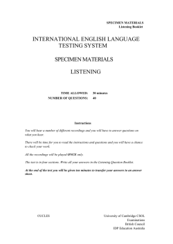
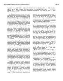
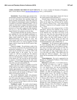
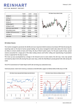
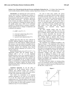
© Copyright 2026