
Download PDF
Intel® Atom™ Processor Z3600
and Z3700 Series
Specification Update
January 2015
Revision 007
Document Number: 329475-007
You may not use or facilitate the use of this document in connection with any infringement or other legal analysis concerning Intel
products described herein. You agree to grant Intel a non-exclusive, royalty-free license to any patent claim thereafter drafted
which includes subject matter disclosed herein.
Intel technologies’ features and benefits depend on system configuration and may require enabled hardware, software or service
activation. Learn more at intel.com, or from the OEM or retailer.
No computer system can be absolutely secure.
Tests document performance of components on a particular test, in specific systems. Differences in hardware, software, or
configuration will affect actual performance. Consult other sources of information to evaluate performance as you consider your
purchase. For more complete information about performance and benchmark results, visit http://www.intel.com/performance.
No license (express or implied, by estoppel or otherwise) to any intellectual property rights is granted by this document. The
products described may contain design defects or errors known as errata which may cause the product to deviate from published
specifications. Current characterized errata are available on request.
All information provided here is subject to change without notice. Contact your Intel representative to obtain the latest Intel
product specifications and roadmaps.
Copies of documents which have an order number and are referenced in this document may be obtained by calling 1-800-548-4725
or visit www.intel.com/design/literature.htm.
Intel, Intel Atom, the Intel logo, are trademarks of Intel Corporation in the U.S. and/or other countries.
*Other names and brands may be claimed as the property of others. See Trademarks on intel.com for full list of Intel trademarks.
© 2015 Intel Corporation.
Specification Update
2
Contents
Preface ................................................................................................................................. 5
Summary Tables of Changes ................................................................................................... 7
Identification Information ...................................................................................................... 15
Component Marking Information............................................................................................. 18
Errata.................................................................................................................................. 19
Specification Changes ........................................................................................................... 44
Specification Clarifications...................................................................................................... 45
Documentation Changes ........................................................................................................ 46
§
Specification Update
3
Revision History
Document
Number
Revision
Number
Description
Revision Date
329475
001
· Initial release
September 2013
329475
002
· Changed title of the Specification Update collateral
· Added SKUs
· Added B-3 stepping errata
November 2013
· Errata
·
Changed Status of VLT5, VLT6, VLT39, VLT43,
VLT44, VLT45
· Added VLT46-VLT57.
329475
003
· Errata
·
329475
004
January 2014
Added VLT58-VLT64
· Changed the title of the Specification Update collateral
· Added SKUs: Z3745, Z3745D, Z3735D, Z3735E,
Z3795, Z3775, Z3775D, Z3735G, Z3735F.
· Added C-0 stepping
May 2014
· Errata
· Changed Status of VLT6, VLT39, VLT43, VLT44,
VLT45
· Added VLT65-VLT68
329475
005
· Added SKU: Z3785, Z3736F, Z3736G.
· Errata
· Added VLT69-VLT76
September 2014
· Specification Clarifications
· Added VLT1
329475
006
· No change
329475
007
· Errata
December 2014
January 2015
· Added VLT77-VLT79
§
4
Specification Update
Preface
Preface
This document is an update to the specifications contained in the documents listed in
the following Affected Documents table. It is a compilation of device and document
errata and specification clarifications and changes, and is intended for hardware
system manufacturers and for software developers of applications, operating system,
and tools.
Information types defined in the Nomenclature section of this document are
consolidated into this document and are no longer published in other documents. This
document may also contain information that has not been previously published.
Note: Throughout this document Intel® Atom™ Processor Z3600 and Z3700 Series SoC is
referred as Processor or SoC.
Affected Documents
Document Title
Document Number1
Intel® Atom™ Processor Z3600 and Z3700 Series Datasheet
329474
NOTE:
1
Contact local Intel representative for the latest document number.
Related Documents
Refer the following documents which may be beneficial when reading this document or
for additional information:
Document
Document Number
Intel® 64 and IA-32 Architectures Software
Developer's Manuals
· Volume 1: Basic Architecture
· Volume 2A: Instruction Set Reference, A-M
· Volume 2B: Instruction Set Reference, N-Z
http://www.intel.com/products/proce
ssor/manuals/index.htm
· Volume 3A: System Programming Guide
· Volume 3B: System Programming Guide
Intel® 64 and IA-32 Architectures Software
Developer’s Manual Documentation Changes
Specification Update
http://www.intel.com/content/www/
us/en/architecture-andtechnology/64-ia-32-architecturessoftware-developers-manual.html
5
Preface
Nomenclature
Errata are design defects or errors in engineering samples. Errata may cause the
processor behavior to deviate from published specifications. Hardware and software
designed to be used with any given stepping assumes that all errata documented for
that stepping are present on all devices.
S-Spec Number is a five-digit code used to identify products. Products are
differentiated by their unique characteristics, that is, core speed, L2 cache size, and
package type as described in the processor identification information table. Read all
notes associated with each S-Spec number.
Specification Changes are modifications to the current published specifications.
These changes will be incorporated in any new release of the specification.
Specification Clarifications describe a specification in greater detail or further
highlight a specification’s impact to a complex design situation. These clarifications will
be incorporated in any new release of the specification.
Documentation Changes include typos, errors, or omissions from the current
published specifications. These will be incorporated in any new release of the
specification.
Note: Errata remain in the specification update throughout the product’s lifecycle, or until a
particular stepping is no longer commercially available. Under these circumstances, errata
removed from the specification update are archived and available upon request. Specification
changes, specification clarifications, and documentation changes are removed from the
specification update when the appropriate changes are made to the appropriate product
specification or user documentation (datasheets, manuals, and so forth).
§
6
Specification Update
Summary Tables of Changes
Summary Tables of Changes
The following table indicates the Specification Changes, Errata, Specification
Clarifications, or Documentation Changes, which apply to the listed steppings. Intel
intends to fix some of the errata in a future stepping of the component, and to
account for the other outstanding issues through documentation or Specification
Changes as noted. This table uses the following notations:
Codes Used in Summary Table
Stepping
X: Erratum, Specification Change or Clarification that applies to this stepping.
(No mark) or (Blank Box): This erratum is fixed in listed stepping or specification
change does not apply to list stepping.
Status
Doc: Document change or update that will be implemented.
Plan Fix: This erratum may be fixed in a future stepping of the product.
Fixed: This erratum has been previously fixed.
No Fix: There is no plan to fix this erratum.
Row
Change bar to left of a table row indicates this erratum is either new or modified from
the previous version of the document.
Stepping
Number
VLT1
VLT2
Specification Update
Status
B-2
B-3
C-0
X
X
X
X
X
X
Errata Title
No Fix
Accessing Unimplemented ISP MMIO
Space May Cause a System Hang
No Fix
Quad Word Transactions in Violation of
Programming Model May Result in
System Hang
7
Summary Tables of Changes
Stepping
Number
VLT3
VLT4
VLT5
VLT6
VLT7
VLT8
VLT9
VLT10
VLT11
VLT12
VLT13
VLT14
VLT15
VLT16
VLT17
8
Status
B-2
B-3
C-0
X
X
X
X
X
X
X
-
-
X
X
-
X
X
X
X
X
X
X
X
X
X
X
X
X
X
X
X
X
X
X
X
X
X
X
X
X
X
X
X
X
X
X
X
X
Errata Title
No Fix
GPIO Registers Do Not Support 8 or
16-bit Transactions
No Fix
CSI Interface May Not Correct Certain
Single-bit Errors
Fixed
ULPI Bus Marginality for USB Device
Mode
Fixed
Anomalies in USB xHCI PME Enable
and PME Status
No Fix
eMMC Asynchronous Abort May Cause
a Hang
No Fix
SD Host Controller Incorrectly Reports
Supporting of Suspend/ Resume
Feature
No Fix
SD Host Controller Error Status
Registers May be Incorrectly Set
No Fix
SD Host Controller Registers Are Not
Cleared by Software Reset
No Fix
Timing Specification Violation on SD
Card Interface
No Fix
SD Card Controller Does Not Disable
Clock During Card Power Down
No Fix
Reset Sequence May Take longer Than
Expected When ACG is Enabled in SD
And SDIO Controllers
No Fix
xHCI Port Assigned Highest SlotID
When Resuming From Sx Issue
No Fix
LFPS Detect Threshold
No Fix
Set Latency Tolerance Value Command
Completion Event Issue
No Fix
xHCI Data Packet Header and Payload
Mismatch Error Condition
Specification Update
Summary Tables of Changes
Stepping
Number
VLT18
VLT19
VLT20
VLT21
VLT22
VLT23
VLT24
VLT25
VLT26
VLT27
VLT28
VLT29
VLT30
VLT31
VLT32
Specification Update
Status
B-2
B-3
C-0
X
X
X
X
X
X
X
X
X
X
X
X
X
X
X
X
X
X
X
X
X
X
X
X
X
X
X
X
X
X
X
X
X
X
X
X
X
X
X
X
X
X
X
X
X
Errata Title
No Fix
USB xHCI SuperSpeed Packet with
Invalid Type Field Issue
No Fix
USB xHCI Behaviour with Three
Consecutive Failed U3 Entry Attempts
No Fix
USB xHCI Max Packet Size and
Transfer Descriptor Length Mismatch
No Fix
USB EHCI RMH Port Disabled Due to
Device Initiated Remote Wake
No Fix
USB EHCI Isoch In Transfer Error
Issue
No Fix
USB EHCI Babble Detected with SW
Overscheduling
No Fix
USB EHCI Full-/low-speed EOP Issue
No Fix
USB EHCI Asynchronous Retries
Prioritized Over Periodic Transfers
No Fix
USB EHCI FS/LS Incorrect Number of
Retries
No Fix
USB EHCI RMH Think Time Issue
No Fix
USB EHCI Full-/low-speed Device
Removal Issue
No Fix
Reported Memory Type May Not Be
Used to Access the VMCS and
Referenced Data Structures
No Fix
A Page Fault May Not be Generated
When the PS bit is set to “1” in a
PML4E or PDPTE
No Fix
CS Limit Violations May Not be
Detected After VM Entry
No Fix
IA32_DEBUGCTL.FREEZE_PERFMON_O
N_PMI is Incorrectly Cleared by SMI
9
Summary Tables of Changes
Stepping
Number
VLT33
Status
B-2
B-3
C-0
X
X
X
X
X
X
VLT34
VLT35
VLT36
VLT37
VLT38
VLT39
VLT40
VLT41
VLT42
VLT43
VLT44
VLT45
10
X
X
X
X
X
X
X
X
X
X
X
X
X
X
-
X
X
X
X
X
X
X
X
X
X
X
-
X
X
-
X
X
-
Errata Title
No Fix
PEBS Record EventingIP Field May be
Incorrect After CS.Base Change
No Fix
Some Performance Counter Overflows
May Not be Logged in
IA32_PERF_GLOBAL_STATUS When
FREEZE_PERFMON_ON_PMI is Enabled
No Fix
MOVNTDQA From WC Memory May
Pass Earlier Locked Instructions
No Fix
Unsynchronized Cross-Modifying Code
Operations Can Cause Unexpected
Instruction Execution Results
No Fix
SDIO Host Controller Does Not Control
the SDIO Bus Power
No Fix
USB HSIC Ports Incorrectly Reported
as Removable
Fixed
Multiple Threads That Access the ISP
Concurrently May Lead to a System
Hang
No Fix
Premature Asynchronous Interrupt
Enabling May Lead to Loss of SDIO WiFi Functionality
No Fix
Paging Structure Entry May be Used
Before Accessed And Dirty Flags Are
Updated
No Fix
Certain eMMC Host Controller
Registers Are Not Cleared by Software
Reset
Fixed
The Display May Flicker After an MIPIDSI LP to HS Transition
Fixed
LPDDR3 Power-Up Timing
Fixed
Using MIPI DSI in LP Mode May Result
in Unpredictable Display Behavior
Specification Update
Summary Tables of Changes
Stepping
Number
Status
B-3
C-0
X
X
X
X
X
X
X
X
X
X
X
X
X
X
X
X
X
X
X
X
X
X
X
X
X
X
X
X
X
X
X
X
X
X
B-2
VLT46
VLT47
VLT48
VLT49
VLT50
VLT51
VLT52
VLT53
VLT54
VLT55
VLT56
VLT57
VLT58
Specification Update
Errata Title
No Fix
USB Device Mode Controller May Not
Successfully Switch to High Speed
Data Rate
No Fix
USB Device Mode Controller Response
Time May Exceed The Specification
No Fix
USB Device Mode Controller May Not
Enter the SS.Inactive State
No Fix
USB EHCI Full-/Low-speed Port Reset
or Clear TT Buffer Request
No Fix
USB Device Mode Controller LFPS
Transmission Period Does Not Meet
USB3.0 Specification
No Fix
Performance Monitor Instructions
Retired Event May Not Count
Consistently
No Fix
MTF VM Exit May be Delayed Following
a VM Entry That Injects a Software
Interrupt
No Fix
LBR Stack And Performance Counter
Freeze on PMI May Not Function
Correctly
No Fix
USB Legacy Support SMI Not Available
from xHCI Controller
No Fix
SD Card UHS-I Mode is Not Fully
Supported
No Fix
EOI Transactions May Not be Sent if
Software Enters Core C6 During an
Interrupt Service Routine
No Fix
USB xHCI May Execute a Stale
Transfer Request Block (TRB)
No Fix
Certain MIPI CSI Sensors May Not
Operate Correctly At Low Clock
Frequencies
11
Summary Tables of Changes
Stepping
Number
VLT59
VLT60
VLT61
VLT62
VLT63
VLT64
VLT65
VLT66
VLT67
VLT68
VLT69
VLT70
VLT71
12
Status
B-2
B-3
C-0
X
X
X
X
X
X
X
X
X
X
X
X
X
X
X
X
X
X
X
X
X
X
X
X
X
X
X
X
X
X
X
X
X
X
X
X
X
X
X
Errata Title
No Fix
SD Card Initialization Sequence May
Fail When ACG is Enabled in SD
Controller
No Fix
Reset Sequence May Not Complete
Under Certain Conditions
No Fix
Multiple Drivers That Access the GPIO
Registers Concurrently May Result in
Unpredictable System Behavior
No Fix
Boot May Not Complete When SMI
Occurs during Boot
No Fix
Interrupts That Target an APIC That is
Being Disabled May Result in a System
Hang
No Fix
Corrected or Uncorrected L2 Cache
Machine Check Errors May Log
Incorrect Address in IA32_MCi_ADDR
No Fix
Software-initiated Partition Reset May
Cause a System Hang
No Fix
Write-1-Clear Bits in PMC Registers
May be Unexpectedly Cleared
No Fix
Port Reset on USB2 Port0 And Port1
May Cause a Reset on HSIC Port0 and
Port1 Respectively
No Fix
Frequency Reported by CPUID
Instruction May Not Match Published
Frequency
No Fix
Machine Check Status Overflow Bit
May Not be Set
No Fix
Attempts to Clear Performance
Counter Overflow Bits May Not
Succeed
No Fix
SMI in 64 Bit Mode May Store an
Incorrect RIP to SMRAM When CS has
a Non-Zero Base
Specification Update
Summary Tables of Changes
Stepping
Number
VLT72
VLT73
VLT74
VLT75
VLT76
VLT77
VLT78
VLT79
Specification Update
Status
B-2
B-3
C-0
X
X
X
X
X
X
X
X
X
X
X
X
X
X
X
X
X
X
X
X
X
X
X
X
Errata Title
No Fix
VM Exit May Set IA32_EFER.NXE When
IA32_MISC_ENABLE Bit 34 is Set to 1
No Fix
Top Swap Mechanism May Become
Incorrectly Configured
No Fix
Certain Peripheral I/O Controllers May
Hang After an Unexpectedly Long
Latency Memory Transaction
No Fix
Disabling SDIO or SDCARD May Lead
To a System Hang
No Fix
System May Hang When Attempting to
Exit an S0ix Idle State
No Fix
TLB Entries May Not Be Invalidated
Properly When Bit 8 Is Set in EPT
Paging-Structure Entries
No Fix
System May Hang During Entry to S0ix
No Fix
CPUID Instruction Leaf 0AH May
Return an Unexpected Value
13
Summary Tables of Changes
Number
Specification Changes
None
Number
VLT1
Specification Clarifications
Top Swap Feature
Number
Documentation Changes
None
§
14
Specification Update
Identification Information
Identification Information
Intel® Atom™ Processor Z3600 and Z3700 Series samples on 22-nm process
processor signature can be identified by the following registers contents:
Table 1. Processor Signature by Using the Programming Interface
Reserved
Extended
Family1
Extended
Model2
Reserved
Processor
Type3
Family
Code4
Model
Number5
Stepping
ID6
31:28
27:20
19:16
15:13
12
11:8
7:4
3:0
0000
00000000b
0011b
000b
0b
0110b
0101b
0001b
NOTES:
1.
The Extended Family, Bits [27:20] are used in conjunction with the Family Code,
specified in Bits [11:8], to indicate whether the processor belongs to the Intel386™,
Intel486™, Pentium®, Pentium® Pro, Pentium® 4, Intel® Core™2, or Intel® Atom™
processor series.
2.
The Extended Model, Bits [19:16] in conjunction with the Model Number, specified in
Bits [7:4], are used to identify the model of the processor within the processor’s family.
3.
The Processor Type, specified in Bits [13:12] indicates whether the processor is an
original OEM processor, an OverDrive processor, or a dual processor (capable of being
used in a dual processor system).
4.
The Family Code corresponds to Bits [11:8] of the EDX register after RESET, Bits
[11:8] of the EAX register after the CPUID instruction is executed with a 1 in the EAX
register, and the generation field of the Device ID register is accessible through
Boundary Scan.
5.
The Model Number corresponds to Bits [7:4] of the EDX register after RESET, Bits [7:4]
of the EAX register after the CPUID instruction is executed with a 1 in the EAX register,
and the model field of the Device ID register is accessible through Boundary Scan.
6.
The Stepping ID in Bits [3:0] indicates the revision number of that model.
When EAX is initialized to a value of 1, the CPUID instruction returns the Extended
Family, Extended Model, Type, Family, Model and Stepping value in the EAX register.
Note: The EDX processor signature value after reset is equivalent to the processor
signature output value in the EAX register.
Specification Update
15
Identification Information
Table 2. Identification Table for Intel® Atom™ Processor Z3600 and Z3700 Series
G-DID/
G-RID2
Base
Frequency
H-DID/
H-RID1
Integrated Graphics
Core Speed
Burst
Frequency
Memory
Frequency
Low
Frequency
Mode
(LFM)
High
Frequency
Mode
(HFM)
Burst
Frequency
Mode
(BFM)
Processor
Number
Stepping
S-Spec
Core Speed
SR1M3
B-2
Z3770
2.4 GHz
1.46 GHz
532 MHz
LPDDR3 1067MT/s
667 MHz
311 MHz
0F00h/09h
0F31h/09h
SR1M5
B-2
Z3740
1.8 GHz
1.33 GHz
532 MHz
LPDDR3 1067MT/s
667 MHz
311 MHz
0F00h/09h
0F31h/09h
SR1M7
B-2
Z3770D
2.4 GHz
1.5 GHz
500 MHz
DDR3L-RS
688 MHz
– 1333MT/s
313 MHz
0F00h/09h
0F31h/09h
SR1M9
B-2
Z3740D
1.83 GHz
1.33 GHz
500 MHz
DDR3L-RS
688 MHz
– 1333MT/s
313 MHz
0F00h/09h
0F31h/09h
SR1RU
B-3
Z3770
2.39 GHz
1.46 GHz
532 MHz
LPDDR3 –
1067 MT/s
667 MHz
311 MHz
0F00h/0Bh
0F31h/0Bh
SR1RW
B-3
Z3740
1.86 GHz
1.33 GHz
532 MHz
LPDDR3 –
1067 MT/s
667 MHz
311 MHz
0F00h/0Bh
0F31h/0Bh
SR1S2
B-3
Z3680
2.0 GHz
1.33 GHz
532 MHz
LPDDR3 –
1067 MT/s
667 MHz
311 MHz
0F00h/0Bh
0F31h/0Bh
SR1RY
B-3
Z3770D
2.4 GHz
1.5 GHz
500 MHz
DDR3L-RS
688 MHz
– 1333MT/s
313 MHz
0F00h/0Bh
0F31h/0Bh
SR1S0
B-3
Z3740D
1.83 GHz
1.33 GHz
500 MHz
DDR3L-RS
688 MHz
– 1333MT/s
313 MHz
0F00h/0Bh
0F31h/0Bh
SR1S4
B-3
Z3680D
2.0 GHz
1.33 GHz
500 MHz
DDR3L-RS
688 MHz
– 1333MT/s
313 MHz
0F00h/0Bh
0F31h/0Bh
SR1SP
C-0
Z3745
1.86 GHz
1.33 GHz
532 MHz
LPDDR3 1067MT/s
778 MHz
311 MHz
0F00h/0Dh
0F31h/0Dh
SR1ST
C-0
Z3745D
1.83Ghz
1.33 GHz
500MHz
DDR3L-RS
792 MHz
– 1333MT/s
313 MHz
0F00h/0Dh
0F31h/0Dh
SR1U7
C-0
Z3735D
1.83Ghz
1.33 GHz
500MHz
DDR3L-RS
646 MHz
– 1333MT/s
313 MHz
0F00h/0Dh 0F31h/0Dh
SR1U9
C-0
Z3735E
1.83Ghz
1.33 GHz
500MHz
DDR3L-RS
646 MHz
– 1333MT/s
313 MHz
0F00h/0Dh 0F31h/0Dh
SR1SK
C-0
Z3795
2.39 GHz
1.66 GHz
532 MHz
LPDDR3 1067MT/s
778 MHz
311 MHz
0F00h/0Dh 0F31h/0Dh
SR1SM
C-0
Z3775
2.39 GHz
1.46 GHz
532 MHz
LPDDR3 1067MT/s
778 MHz
311 MHz
0F00h/0Dh 0F31h/0Dh
SR1SR
C-0
Z3775D
2.416 GHz
1.5 GHz
500 MHz
DDR3L-RS
792 MHz
– 1333MT/s
313 MHz
0F00h/0Dh 0F31h/0Dh
SR1UD
C-0
Z3735G
1.83 GHz
1.33 GHz
500 MHz
DDR3L-RS
646 MHz
– 1333MT/s
313 MHz
0F00h/0Dh 0F31h/0Dh
16
Specification Update
Identification Information
G-DID/
G-RID2
Base
Frequency
H-DID/
H-RID1
Integrated Graphics
Core Speed
Burst
Frequency
Memory
Frequency
Low
Frequency
Mode
(LFM)
High
Frequency
Mode
(HFM)
Burst
Frequency
Mode
(BFM)
Processor
Number
Stepping
S-Spec
Core Speed
SR1UB
C-0
Z3735F
1.83 GHz
1.33 GHz
500 MHz
DDR3L-RS
646 MHz
– 1333MT/s
313 MHz
0F00h/0Dh
SR1V9
C-0
Z3785
2.416 GHz
1.5 GHz
500 MHz
LPDDR3 1333MT/s
833 MHz
313 MHz
0F00h/0Dh 0F31h/0Dh
SR20D
C-0
Z3736F
2.16 GHz
1.33 GHz
500 MHz
DDR3L-RS
646 MHz
– 1333MT/s
313 MHz
0F00h/0Dh
0F31h/0Dh
SR20E
C-0
Z3736G
2.16 GHz
1.33 GHz
500 MHz
DDR3L-RS
646 MHz
– 1333MT/s
313 MHz
0F00h/0Dh
0F31h/0Dh
NOTES:
1.
H-DID – Host Device ID; H-RID – Host Revision ID (H-RID are last three Bits of H-DID)
2.
G-DID – Graphics Device ID; G-RID – Graphics Revision ID (G-RID are last three Bits
of G-DID)
§
Specification Update
17
0F31h/0Dh
Component Marking Information
Component Marking Information
Processor shipments can be identified by the following component markings and
example pictures.
Figure 1. Intel® Atom™ Processor Z3600 and Z3700 Component Marking Information
SAMPLE MARKING INFORMATION:
GRP1LINE1: i{M}{C}YY
GRP2LINE1: FPO12345
§
18
Specification Update
Errata
Errata
VLT1
Accessing Unimplemented ISP MMIO Space May Cause a System Hang
Problem:
Access to unimplemented ISP (Image Signal Processor) registers should result in a
software error. Due to this erratum, the transaction may not complete.
Implication: When this erratum occurs, the system may hang.
Workaround: Do not access unimplemented ISP MMIO space.
Status:
For the steppings affected, see the Summary Tables of Changes.
VLT2
Quad Word Transactions in Violation of Programming Model May
Result in System Hang
Problem:
Quad word (64 bit data) transactions to access two adjacent 32-bit registers of SoC
internal devices may cause system hang.
Implication: Due to this erratum, violations of a device programming model may result in a hang
instead of a fatal Target Abort / Completer Abort error. Software written in compliance
to correct programming model will not be affected.
Workaround: Software must be written and compiled in compliance to correct programming model.
Status:
For the steppings affected, see the Summary Tables of Changes.
VLT3
GPIO Registers Do Not Support 8 or 16 bit Transactions
Problem:
Due to this erratum, only aligned DWord accesses to GPIO registers function
correctly. This erratum applies to GPIO registers whether in MMIO space or IO space.
Implication: GPIO register transactions using byte or word accesses or unaligned DWord accesses
will not work correctly.
Workaround: Always use aligned 32 bit transactions when accessing GPIO registers.
Status:
For the steppings affected, see the Summary Tables of Changes.
Specification Update
19
Errata
VLT4
CSI Interface May Not Correct Certain Single bit Errors
Problem:
The CSI (Camera Serial Interface) ECC (Error Correcting Code) implementation may
not correctly handle single-bit errors in the ECC field and may incorrectly flag as
double-bit errors.
Implication: Due to this erratum, some single-bit errors may be treated as double-bit errors. Intel
has not observed this erratum with any commercially available software or system.
Workaround: None identified.
Status:
For the steppings affected, see the Summary Tables of Changes.
VLT5
ULPI Bus Marginality for USB Device Mode
Problem:
USB device mode is supported by the SoC via the ULPI (UTMI+ Low Pin Interface)
bus. The ULPI bus may exhibit read timing marginalities resulting in a hold time
violation.
Implication: Due to this erratum, the SoC ULPI reads may be unreliable.
Workaround: None identified.
Status:
For the steppings affected, see the Summary Tables of Changes.
VLT6
Anomalies in USB xHCI PME Enable and PME Status
Problem:
The PME_En (bit 8) and PME_Status (bit 15) in xHCI’s PCI PMCSR (Bus 0, Device 20,
Function 0, Offset 0x74) do not comply with the PCI specification.
Implication: If a standard bus driver model for this register is applied, wake issues and system
slowness may happen.
Workaround: A BIOS code change has been identified and may be implemented as a workaround for
this erratum.
Status:
For the steppings affected, see the Summary Tables of Changes.
VLT7
eMMC Asynchronous Abort May Cause a Hang
Problem:
Use of an Asynchronous Abort command to recover from an eMMC transfer error or
use of a high priority interrupt STOP_TRANSMISSION command may result in a hang.
Implication: Using Asynchronous Abort command may cause a hang. Intel has not observed this
erratum to impact the operation of any commercially available system.
Workaround: The eMMC driver should use High Priority Interrupt SEND_STATUS mode per JEDEC
STANDARD eMMC, version 4.5. A minimum wait time of 128us between getting an
error interrupt and issuing a software reset will avoid this erratum.
Status:
20
For the steppings affected, see the Summary Tables of Changes.
Specification Update
Errata
VLT8
SD Host Controller Incorrectly Reports Supporting of Suspend/
Resume Feature
Problem:
SDIO, SD Card, and eMMC Controllers should not indicate the support of optional
Suspend/Resume feature documented in the SD Host Controller Standard Specification
Version 3.0. Due to this erratum, the default value in the Capabilities Register (offset
040H) incorrectly indicates to the software that this feature is supported.
Implication: If software utilizes the Suspend/Resume feature, data may not be correctly
transferred between memory and SD device.
Workaround: A BIOS code change has been identified and may be implemented as a workaround
for this erratum.
Status:
For the steppings affected, see the Summary Tables of Changes.
VLT9
SD Host Controller Error Status Registers May be Incorrectly Set
Problem:
This erratum impacts SDIO, SD Card, and eMMC SD Host Controllers. Auto CMD Error
Status Register (offset 03CH, Bits [7:1]) may be incorrectly set for software-issued
commands (for example: CMD13) that generate errors when issued close to the
transmission of an Auto CMD12 command. In addition, the Error Interrupt Status
Register Bits (offset 032H) are similarly affected.
Implication: Software may not be able to interpret SD Host controller error status.
Workaround: Software should follow the same error recovery flow whenever an error status bit is
set. Alternatively, don’t use software-issued commands which have Auto CMD12
enabled.
Status:
For the steppings affected, see the Summary Tables of Changes.
VLT10
SD Host Controller Registers Are Not Cleared by Software Reset
Problem:
This erratum impacts SDIO, SD Card, and eMMC SD Host Controllers. When Software
Reset is asserted, registers such as SDMA System Address / Argument 2 (offset 00H)
in SD Host Controller are not cleared, failing to comply with the SD Host Controller
Specification 3.0.
Implication: Intel has not observed this erratum to impact any commercially available software.
Workaround: Driver is expected to reprogram these registers before issuing a new command.
Status:
For the steppings affected, see the Summary Tables of Changes.
VLT11
Timing Specification Violation on SD Card Interface
Problem:
SD Card interface IO circuitry is not optimized for platform conditions during operation
at 3.3V.
Implication: Due to this erratum, there is an increased risk of a transfer error.
Workaround: A BIOS code change has been identified and may be implemented as a workaround for
this erratum.
Status:
For the steppings affected, see the Summary Tables of Changes.
Specification Update
21
Errata
VLT12
SD Card Controller Does Not Disable Clock during Card Power Down
Problem:
The clock and power control of the SD card controller are not linked. Therefore, the
SD card controller does not automatically disable the SD card clock when the SD card
power is disabled.
Implication: When an SD card is inserted into the system and powered off, the clock to the SD card
will continue to be driven. Although this behavior is common, it is a violation of the SD
Card Spec 3.0.
Workaround: To address this problem, the SD card clock should be enabled/disabled in conjunction
with SD card power.
Status:
For the steppings affected, see the Summary Tables of Changes.
VLT13
Reset Sequence May Take Longer Than Expected When ACG is
Enabled in SD and SDIO Controllers
Problem:
When ACG (Auto Clock Gating) is enabled in SD and SDIO controllers, the reset
sequence may take longer than expected, possibly resulting in a software timeout.
Implication: Due to this erratum, a longer response time may be observed after a softwareinitiated controller reset.
Workaround: A BIOS code change has been identified and may be implemented as a workaround
for this erratum.
Status:
For the steppings affected, see the Summary Tables of Changes.
VLT14
xHCI Port Assigned Highest SlotID When Resuming from Sx Issue
Problem:
If a device is attached while the platform is in S3 or S4 and the device is assigned the
highest assignable Slot ID upon resume, the xHCI may attempt to access an
unassigned main memory address.
Implication: Accessing unassigned main memory address may cause a system software timeout
leading to possible system hang.
Workaround: System SW can detect the timeout and perform a host controller reset prior to avoid a
system hang.
Status:
22
For the steppings affected, see the Summary Tables of Changes.
Specification Update
Errata
VLT15
LFPS Detect Threshold
Problem:
The USB 3.0 host and device controllers’ LFPS (Low Frequency Periodic Signal) detect
threshold is higher than the USB 3.0 specification maximum of 300 mV.
Implication: The USB 3.0 host and device controllers may not recognize LFPS from SuperSpeed
devices transmitting at the minimum low power peak-to-peak differential voltage (400
mV) as defined by USB 3.0 specification for the optional capability for Low-Power
swing mode. Intel has not observed this erratum to impact the operation of any
commercially available system.
Workaround: None identified.
Status:
For the steppings affected, see the Summary Tables of Changes.
VLT16
Set Latency Tolerance Value Command Completion Event Issue
Problem:
The xHCI controller does not return a value of ‘0’ for slot ID in the command
completion event TRB (Transfer Request Block) for a set latency tolerance value
command.
Note: This violates the command completion event TRB description in section 6.4.2.2 of the
eXtensible Host Controller Interface for Universal Serial Bus (xHCI) specification, revision 1.0.
Implication: There are no known functional failures due to this issue.
Note: Set latency tolerance value command is specific to the controller and not the slot.
Software knows which command was issued and which fields are valid to check for the event.
Note: xHCI CV compliance test suite: Test TD4.10: Set Latency Tolerance Value Command
Test may issue a warning.
Workaround: None identified
Status:
For the steppings affected, see the Summary Tables of Changes.
VLT17
xHCI Data Packet Header and Payload Mismatch Error Condition
Problem:
If a SuperSpeed device sends a DPH (Data Packet Header) to the xHCI with a data
length field that specifies less data than is actually sent in the DPP (Data Packet
Payload), the xHCI will accept the packet instead of discarding the packet as invalid.
Note: The USB 3.0 specification requires a device to send a DPP matching the amount of
data specified by the DPH.
Implication: The amount of data specified in the DPH will be accepted by the xHCI and the
remaining data will be discarded and may result in anomalous system behavior.
Note: This issue has only been observed in a synthetic test environment with a synthetic
device.
Workaround: None identified
Status:
For the steppings affected, see the Summary Tables of Changes.
Specification Update
23
Errata
VLT18
USB xHCI SuperSpeed Packet with Invalid Type Field Issue
Problem:
If the encoding for the “type” field for a SuperSpeed packet is set to a reserved value
and the encoding for the “subtype” field is set to “ACK”, the xHCI may accept the
packet as a valid acknowledgement transaction packet instead of ignoring the packet.
Note: The USB 3.0 specification requires that a device never set any defined fields to
reserved values.
Implication: System implication is dependent on the misbehaving device and may result in
anomalous system behavior.
Note: This issue has only been observed in a synthetic test environment with a synthetic
device.
Workaround: None identified
Status:
For the steppings affected, see the Summary Tables of Changes.
VLT19
USB xHCI Behavior with Three Consecutive Failed U3 Entry Attempts
Problem:
The xHCI does not transition to the SS.Inactive USB 3.0 LTSSM (Link Training and
Status State Machine) state after a SuperSpeed device fails to enter U3 upon three
consecutive attempts.
Note: The USB 3.0 specification requires a SuperSpeed device to enter U3 when directed.
Implication: The xHCI will continue to try to initiate U3. The implication is driver and operating
system dependent.
Workaround: None identified
Status:
For the steppings affected, see the Summary Tables of Changes.
VLT20
USB xHCI Max Packet Size and Transfer Descriptor Length Mismatch
Problem:
The xHCI may incorrectly handle a request from a low-speed or full-speed device
when all the following conditions are true:
· The sum of the packet fragments equals the length specified by the TD (Transfer
Descriptor)
· The TD length is less than the MPS (Max Packet Size) for the device
· The last packet received in the transfer is “0” or babble bytes
Implication: The xHCI will halt the endpoint if all the above conditions are met. All functions
associated with the endpoint will stop functioning until the device is unplugged and
reinserted.
Workaround: None identified
Status:
24
For the steppings affected, see the Summary Tables of Changes.
Specification Update
Errata
VLT21
USB EHCI RMH Port Disabled Due to Device Initiated Remote Wake
Problem:
During resume from Global Suspend, the RMH controller may not send SOF soon
enough to prevent a device from entering suspend again. A collision on the port may
occur if a device initiated remote wake occurs before the RMH controller sends SOF.
Note: Intel has only observed this issue when two USB devices on the same RMH controller
send remote wake within 30 ms window while RMH controller is resuming from Global
Suspend
Implication: The RMH host controller may detect the collision as babble and disable the port.
Workaround: Intel recommends system software to check bit 3 (Port Enable/Disable Change)
together with bit 7 (Suspend) of Port N Status and Control PORTC registers when
determining which port(s) have initiated remote wake. Intel recommends the use of
the USB xHCI controller which is not affected by this erratum.
Status:
For the steppings affected, see the Summary Tables of Changes.
VLT22
USB EHCI Isoch in Transfer Error Issue
Problem:
If a USB full-speed inbound isochronous transaction with a packet length 190 bytes or
greater is started near the end of a microframe the SoC may see more than 189 bytes
in the next microframe.
Implication: If the SoC sees more than 189 bytes for a microframe an error will be sent to software
and the isochronous transfer will be lost. If a single data packet is lost no perceptible
impact for the end user is expected.
Note: Intel has only observed the issue in a synthetic test environment where precise
control of packet scheduling is available, and has not observed this failure in its compatibility
validation testing.
· Isochronous traffic is periodic and cannot be retried thus it is considered good
practice for software to schedule isochronous transactions to start at the beginning
of a microframe. Known software solutions follow this practice.
· To sensitize the system to the issue additional traffic such as other isochronous
transactions or retries of asynchronous transactions would be required to push the
inbound isochronous transaction to the end of the microframe.
Workaround: Intel recommends the use of the USB xHCI controller which is not affected by this
erratum.
Status:
For the steppings affected, see the Summary Tables of Changes.
VLT23
USB EHCI Babble Detected with SW Overscheduling
Problem:
If software violates USB periodic scheduling rules for full-speed isochronous traffic by
overscheduling, the RMH may not handle the error condition properly and return a
completion split with more data than the length expected.
Implication: If the RMH returns more data than expected, the endpoint will detect packet babble
for that transaction and the packet will be dropped. Since overscheduling occurred to
create the error condition, the packet would be dropped regardless of RMH behavior.
Specification Update
25
Errata
If a single isochronous data packet is lost, no perceptible impact to the end user is
expected.
Note: USB software overscheduling occurs when the amount of data scheduled for a
microframe exceeds the maximum budget. This is an error condition that violates the USB
periodic scheduling rule.
Note: This failure has only been recreated synthetically with USB software intentionally
overscheduling traffic to hit the error condition.
Workaround: Intel recommends the use of the USB xHCI controller which is not affected by this
erratum.
Status:
For the steppings affected, see the Summary Tables of Changes.
VLT24
USB EHCI Full-/low-speed EOP Issue
Problem:
If the EOP of the last packet in a USB Isochronous split transaction (Transaction >189
bytes) is dropped or delayed 3 ms or longer the following may occur:
· If there are no other pending low-speed or full-speed transactions the RMH will not
send SOF, or Keep-Alive. Devices connected to the RMH will interpret this condition
as idle and will enter suspend.
· If there is other pending low-speed or full-speed transactions, the RMH will drop the
isochronous transaction and resume normal operation.
Implication: If there are no other transactions pending, the RMH is unaware a device has entered
suspend and may start sending a transaction without waking the device. The
implication is device dependent, but a device may stall and require a reset to resume
functionality. If there are other transactions present, only the initial isochronous
transaction may be lost. The loss of a single isochronous transaction may not result in
end user perceptible impact.
Note: Intel has only observed this failure when using software that does not comply with
the USB specification and violates the hardware isochronous scheduling threshold by
terminating transactions that are already in progress
Workaround: Intel recommends the use of the USB xHCI controller which is not affected by this
erratum.
Status:
26
For the steppings affected, see the Summary Tables of Changes.
Specification Update
Errata
VLT25
USB EHCI Asynchronous Retries Prioritized Over Periodic Transfers
Problem:
The integrated USB RMH incorrectly prioritizes full-speed and low-speed asynchronous
retries over dispatchable periodic transfers.
Implication: Periodic transfers may be delayed or aborted. If the asynchronous retry latency
causes the periodic transfer to be aborted, the impact varies depending on the nature
of periodic transfer:
· If a periodic interrupt transfer is aborted, the data may be recovered by the next
instance of the interrupt or the data could be dropped.
· If a periodic isochronous transfer is aborted, the data will be dropped. A single
dropped periodic transaction should not be noticeable by end user.
Note: This issue has only been seen in a synthetic environment. The USB spec does not
consider the occasional loss of periodic traffic a violation
Workaround: Intel recommends the use of the USB xHCI controller which is not affected by this
erratum.
Status:
For the steppings affected, see the Summary Tables of Changes.
VLT26
USB EHCI FS/LS Incorrect Number of Retries
Problem:
A USB low-speed transaction may be retried more than three times, and a USB fullspeed transaction may be retried less than three times if all of the following conditions
are met:
· A USB low-speed transaction with errors or the first retry of the transaction occurs
near the end of a microframe, and there is not enough time to complete another
retry of the low-speed transaction in the same microframe.
· There is pending USB full-speed traffic and there is enough time left in the
microframe to complete one or more attempts of the full-speed transaction.
· Both the low-speed and full-speed transactions must be asynchronous
(Bulk/Control) and must have the same direction either in or out.
Note: Per the USB EHCI Specification a transaction with errors should be attempted a
maximum of 3 times if it continues to fail.
Implication: For low-speed transactions the extra retry(s) allow a transaction additional chance(s)
to recover regardless of if the full-speed transaction has errors or not. If the fullspeed transactions also have errors, the SoC may retry the transaction fewer times
than required, stalling the device prematurely. Once stalled, the implication is
software dependent, but the device may be reset by software.
Workaround: Intel recommends the use of the USB xHCI controller which is not affected by this
erratum.
Status:
For the steppings affected, see the Summary Tables of Changes.
Specification Update
27
Errata
VLT27
USB EHCI RMH Think Time Issue
Problem:
The USB RMH Think Time may exceed its declared value in the RMH hub descriptor
register of 8 full-speed bit times.
Implication: If the USB driver fully subscribes a USB microframe, LS/FS transactions may exceed
the microframe boundary.
Note: No functional failures have been observed.
Workaround: Intel recommends the use of the USB xHCI controller which is not affected by this
erratum.
Status:
For the steppings affected, see the Summary Tables of Changes.
VLT28
USB EHCI Full-/low-speed Device Removal Issue
Problem:
If two or more USB full-/low-speed devices are connected to the EHCI USB controller,
the devices are not suspended, and one device is removed, one or more of the devices
remaining in the system may be affected by the disconnect.
Implication: The implication is device dependent. A device may experience a delayed transaction,
stall and be recovered via software, or stall and require a reset such as a hot plug to
resume normal functionality.
Workaround: Intel recommends the use of the USB xHCI controller which is not affected by this
erratum.
Status:
For the steppings affected, see the Summary Tables of Changes.
VLT29
Reported Memory Type May Not Be Used to Access the VMCS and
Referenced Data Structures
Problem:
Bits 53:50 of the IA32_VMX_BASIC MSR report the memory type that the processor
uses to access the VMCS and data structures referenced by pointers in the VMCS. Due
to this erratum, a VMX access to the VMCS or referenced data structures will instead
use the memory type that the MTRRs (memory-type range registers) specify for the
physical address of the access.
Implication: Bits 53:50 of the IA32_VMX_BASIC MSR report that the WB (write-back) memory
type will be used but the processor may use a different memory type.
Workaround: Software should ensure that the VMCS and referenced data structures are located at
physical addresses that are mapped to WB memory type by the MTRRs.
Status:
28
For the steppings affected, see the Summary Tables of Changes.
Specification Update
Errata
VLT30
A Page Fault May Not be Generated When the PS bit is set to “1” in a
PML4E or PDPTE
Problem:
On processors supporting Intel® 64 architecture the PS bit (Page Size bit 7) is
reserved in PML4Es and PDPTEs. If the translation of the linear address of a memory
access encounters a PML4E or a PDPTE with PS set to 1 a page fault should occur. Due
to this erratum, PS of such an entry is ignored and no page fault will occur due to its
being set.
Implication: Software may not operate properly if it relies on the processor to deliver page faults
when reserved Bits are set in paging-structure entries.
Workaround: Software should not set bit 7 in any PML4E or PDPTE that has Present bit (bit 0) set to
“1”.
Status:
For the steppings affected, see the Summary Tables of Changes.
VLT31
CS Limit Violations May Not be detected after VM Entry
Problem:
The processor may fail to detect a CS limit violation on fetching the first instruction
after VM entry if the first byte of that instruction is outside the CS limit but the last
byte of the instruction is inside the limit.
Implication: The processor may erroneously execute an instruction that should have caused a
general protection exception.
Workaround: When a VMM emulates a branch instruction it should inject a general protection
exception if the instruction’s target EIP is beyond the CS limit.
Status:
For the steppings affected, see the Summary Tables of Changes.
VLT32
IA32_DEBUGCTL.FREEZE_PERFMON_ON_PMI is Incorrectly Cleared
by SMI
Problem:
FREEZE_PERFMON_ON_PMI (bit 12) in the IA32_DEBUGCTL MSR (1D9H) is
erroneously cleared during delivery of an SMI (system-management interrupt).
Implication: As a result of this erratum the performance monitoring counters will continue to count
after a PMI occurs in SMM (system-management Mode).
Workaround: None identified.
Status:
For the steppings affected, see the Summary Tables of Changes.
Specification Update
29
Errata
VLT33
PEBS Record EventingIP Field May be Incorrect after CS.Base Change
Problem:
Due to this erratum a PEBS (Precise Event Base Sampling) record generated after an
operation which changes CS.Base may contain an incorrect address in the EventingIP
field.
Implication: Software attempting to identify the instruction which caused the PEBS event may
identify the incorrect instruction when non-zero CS.Base is supported and CS.Base is
changed. Intel has not observed this erratum to impact the operation of any
commercially available system.
Workaround: None identified.
Status:
For the steppings affected, see the Summary Tables of Changes.
VLT34
Some Performance Counter Overflows May Not be logged in
IA32_PERF_GLOBAL_STATUS When FREEZE_PERFMON_ON_PMI is
enabled
Problem:
When enabled, FREEZE_PERFMON_ON_PMI bit 12 in IA32_DEBUGCTL MSR (1D9H)
freezes PMCs (performance monitoring counters) on a PMI (Performance Monitoring
Interrupt) request by clearing the IA32_PERF_GLOBAL_CTRL MSR (38FH). Due to this
erratum, when FREEZE_PERFMON_ON_PMI is enabled and two or more PMCs overflow
within a small window of time and PMI is requested, then subsequent PMC overflows
may not be logged in IA32_PERF_GLOBAL_STATUS MSR (38EH).
Implication: On a PMI, subsequent PMC overflows may not be logged in
IA32_PERF_GLOBAL_STATUS MSR.
Workaround: Re-enabling the PMCs in IA32_PERF_GLOBAL_CTRL will log the overflows that were
not previously logged in IA32_PERF_GLOBAL_STATUS.
Status:
For the steppings affected, see the Summary Tables of Changes.
VLT35
MOVNTDQA from WC Memory May Pass Earlier Locked Instructions
Problem:
An execution of MOVNTDQA that loads from WC (write combining) memory may
appear to pass an earlier locked instruction to a different cache line.
Implication: Software that expects a lock to fence subsequent MOVNTDQA instructions may not
operate properly. If the software does not rely on locked instructions to fence the
subsequent execution of MOVNTDQA then this erratum does not apply.
Workaround: Software that requires a locked instruction to fence subsequent executions of
MOVNTDQA should insert an LFENCE instruction before the first execution of
MOVNTDQA following the locked instruction. If there is already fencing or serializing
instruction between the locked instruction and the MOVNTDQA, then an additional
LFENCE is not necessary.
Status:
30
For the steppings affected, see the Summary Tables of Changes.
Specification Update
Errata
VLT36
Unsynchronized Cross-Modifying Code Operations Can Cause
Unexpected Instruction Execution Results
Problem:
The act of one processor or system bus master writing data into a currently executing
code segment of a second processor with the intent of having the second processor
execute that data as code is called cross-modifying code (XMC). XMC that does not
force the second processor to execute a synchronizing instruction prior to execution of
the new code is called unsynchronized XMC. Software using unsynchronized XMC to
modify the instruction byte stream of a processor can see unexpected or unpredictable
execution behavior from the processor that is executing the modified code.
Implication: In this case the phrase "unexpected or unpredictable execution behavior"
encompasses the generation of most of the exceptions listed in the Intel Architecture
Software Developer's Manual Volume 3: System Programming Guide including a
General Protection Fault (GPF) or other unexpected behaviors. In the event that
unpredictable execution causes a GPF the application executing the unsynchronized
XMC operation would be terminated by the operating system.
Workaround: In order to avoid this erratum programmers should use the XMC synchronization
algorithm as detailed in the Intel Architecture Software Developer's Manual Volume 3:
System Programming Guide Section: Handling Self- and Cross-Modifying Code.
Status:
For the steppings affected, see the Summary Tables of Changes.
VLT37
SDIO Host Controller Does Not Control the SDIO Bus Power
Problem:
The SD Bus Power bit in Power Control Register (Bus 0; Device 17; Function 0; Offset
029H) is not connected to any SOC IO pin that can reset the SDIO bus power. Due to
this erratum, SDIO device Power-On-Reset cannot be controlled by Power Control
Register. SDIO Controller may fail to comply with SD Host Controller Specification
Version 3.00.
Implication: SDIO devices may not be powered up and initialized correctly.
Workaround: Software should be configured to use a GPIO pin on the platform to enable or disable
the SDIO bus power.
Status:
For the steppings affected, see the Summary Tables of Changes.
VLT38
USB HSIC Ports Incorrectly Reported as Removable
Problem:
The DR (Device Removable) bit in the PORTSC registers of the two USB HSIC ports
incorrectly indicates that devices on these ports may be removed.
Implication: Software that relies solely on the state of DR bits will consider fixed devices to be
removable. This may lead the software to improper actions (e.g. requesting the user
remove a fixed device).
Workaround: In conjunction with the DR bits, software should use BIOS-configured ACPI tables and
factor in the CONNECTABLE field of the USB Port Capabilities object when determining
whether a port is removable.
Status:
For the steppings affected, see the Summary Tables of Changes.
VLT39
Multiple Threads That Access the ISP Concurrently May Lead to a
System Hang
Specification Update
31
Errata
Problem:
The ISP (Image Signal Processor) may not be able to process concurrent accesses.
Implication: If multiple software threads access the ISP concurrently, it may lead to system hang
during video recording, still image capture or preview modes.
Workaround: Avoid using multiple threads that may concurrently access the ISP. The Intel-provided
drivers implement this workaround.
Status:
For the steppings affected, see the Summary Tables of Changes.
VLT40
Premature Asynchronous Interrupt Enabling May Lead to Loss of
SDIO Wi-Fi Functionality
Problem:
Setting the SDIO controller’s Host Control 2 Register Asynchronous Interrupt Enable
(Bus 0; Device 17; Function 0; Offset 03EH, bit 14) to ‘1’ before the signal voltage
switch sequence completion may result in SDIO card initialization failure.
Implication: SDIO card initialization failure may lead to software time out and loss of Wi-Fi device
functionality. Currently released common operating system drivers do not use
Asynchronous Interrupt mode.
Workaround: The SDIO driver should either use SDIO Synchronous Interrupt Mode or enable SDIO
Asynchronous Interrupt Mode after the SDIO card signal voltage switch sequence
completes.
Status:
For the steppings affected, see the Summary Tables of Changes.
VLT41
Paging Structure Entry May be Used Before Accessed And Dirty Flags
Are Updated
Problem:
If software modifies a paging structure entry while the processor is using the entry for
linear address translation, the processor may erroneously use the old value of the
entry to form a translation in a TLB (or an entry in a paging structure cache) and then
update the entry’s new value to set the accessed flag or dirty flag. This will occur only
if both the old and new values of the entry result in valid translations.
Implication: Incorrect behavior may occur with algorithms that atomically check that the accessed
flag or the dirty flag of a paging structure entry is clear and modify other parts of that
paging structure entry in a manner that results in a different valid translation.
Workaround: Affected algorithms must ensure that appropriate TLB invalidation is done before
assuming that future accesses do not use translations based on the old value of the
paging structure entry.
Status:
32
For the steppings affected, see the Summary Tables of Changes.
Specification Update
Errata
VLT42
Certain eMMC Host Controller Registers Are Not Cleared by Software
Reset
Problem:
Due to this erratum, when an eMMC Host Controller software reset is requested by
setting bit 0 of the Software Reset Register (Offset 2FH), the Command Response
Register (Offset 10H) and ADMA Error Status Register (Offset 54H) are not cleared.
This does not comply with the SD Host Controller Specification 3.0.
Implication: Intel has not observed this erratum to impact any commercially available software.
Workaround: Software should not read these registers until a response is received from the eMMC
device.
Status:
For the steppings affected, see the Summary Tables of Changes.
VLT43
The Display May Flicker After an MIPI-DSI LP to HS Transition
Problem:
Due to this erratum, when the MIPI (Mobile Industry Processor Interface) display PHY
switches from LP (low power) mode to HS (high speed) mode, there is a brief interval
(50 ns) where the four MIPI DSI (Display Serial Interface) data lanes may not be
synchronized.
Implication: The effects are MIPI Panel dependent. Intel has observed display flicker on some MIPI
Panels.
Workaround: Workaround for this erratum is panel dependent and can be implemented in firmware
or software.
Status:
For the steppings affected, see the Summary Tables of Changes.
VLT44
LPDDR3 Power-Up Timing
Problem:
JEDEC Standard JESD209-3 requires a minimum additional time (denoted by tMRRI)
after an “exit from standby, idle power-down mode” before any MRR (Mode Register
Read) command can be issued. Due to this erratum, the SoC may not comply with the
tMRRI specification.
Implication: Intel has not observed this erratum to impact the functionality or performance of any
commercially available LPDDR3 memory parts operating at speeds up to 1067MT/s.
Workaround: None identified.
Status:
For the steppings affected, see the Summary Tables of Changes.
Specification Update
33
Errata
VLT45
Using MIPI DSI in LP Mode May Result in Unpredictable Display
Behavior
Problem:
DSI (Display Serial Interface) commands sent in LP (low power) mode to the MIPI
(Mobile Industry Processor Interface) DSI controller may fail to execute if the
controller is configured to be clocked by the DSI PLL.
Implication: When this erratum occurs, the display panel will behave unpredictably.
Workaround: The display driver can avoid the conditions necessary for this erratum by either using
HS (High Speed) mode for sending all DSI commands or selecting PLL Bypass Mode
for all LP mode operations and DSI PLL for HS mode. The Intel display drivers
implement this workaround.
Status:
For the steppings affected, see the Summary Tables of Changes.
VLT46
USB Device Mode Controller May Not Successfully Switch to High
Speed Data Rate
Problem:
The USB Device Mode Controller may initiate speed change to High Speed data rate
immediately following a reset of a discrete ULPI (UTMI+ Low Pin Interface) compliant
PHY (physical layer) device.
Implication: Some ULPI-compliant PHYs may not recognize the USB Device Mode Controller speed
change and thus may not be able to support USB High Speed operation.
Workaround: None identified.
Status:
For the steppings affected, see the Summary Tables of Changes.
VLT47
USB Device Mode Controller Response Time May Exceed The
Specification
Problem:
The USB ULPI specification allocates 112 bit times for the USB Device Mode controller
to respond to requests. Due to this erratum, the SoC’s Device Mode controller may
exceed this specification.
Implication: USB response time may exceed specifications in configurations with maximal total
USB cable length, resulting in communication failure.
Workaround: Limit the total cable length used to connect to the host to less than 24m to
compensate for the additional controller response time.
Status:
For the steppings affected, see the Summary Tables of Changes.
VLT48
USB Device Mode Controller May Not Enter the SS.Inactive State
Problem:
When operating at SuperSpeed rates, the PENDING_HP_TIMER is used to detect lost
or corrupted acknowledgements. The USB3.0 specification requires a USB port to
transition to the SS.Inactive state on the fourth consecutive timeout. Due to this
erratum, the USB device mode controller in device mode will continue to enter
Recovery state and not enter the SS.Inactive state.
Implication: This behavior does not comply with the USB3.0 specification. Intel has not observed
this erratum to impact the operation of any commercially available system.
34
Specification Update
Errata
Workaround: None identified.
Status:
For the steppings affected, see the Summary Tables of Changes.
VLT49
USB EHCI Full-/Low-speed Port Reset or Clear TT Buffer Request
Problem:
One or more full-/low-speed USB devices on the same RMH controller may be affected
if the devices are not suspended and either (a) software issues a Port Reset OR (b)
software issues a Clear TT Buffer request to a port executing a split full-/low-speed
Asynchronous Out command. The small window of exposure for full-speed device is
around 1.5 microseconds and around 12 microseconds for a low-speed device.
Implication: The affected port may stall or receive stale data for a newly arrived split transfer
occurring at the time of the Port Reset or Clear TT Buffer request.
Note: This issue has only been observed in a synthetic test environment.
Workaround: Intel recommends the use of the USB xHCI controller which is not affected by this
erratum.
Status:
For the steppings affected, see the Summary Tables of Changes.
VLT50
USB Device Mode Controller LFPS Transmission Period Does Not Meet
USB3.0 Specification
Problem:
Upon USB Device Mode Controller SuperSpeed U1 (low-power state) exit, the LFPS
(Low-Frequency Periodic Signaling) signal may be transmitted for less than the 600ns
required by USB3.0 specification.
Implication: In case of concurrent U1 exit by both sides of the USB link, there may be insufficient
LFPS duration to ensure the exit is successful. In cases where U1 exit does not
succeed, host software will typically initiate link recovery. Intel has not observed this
erratum with any commercially available systems.
Workaround: None identified.
Status:
For the steppings affected, see the Summary Tables of Changes.
VLT51
Performance Monitor Instructions Retired Event May Not Count
Consistently
Problem:
Performance Monitor Instructions Retired (Event C0H; Umask 00H) and the instruction
retired fixed counter (IA32_FIXED_CTR0 MSR (309H)) are used to track the number of
instructions retired. Due to this erratum, certain situations may cause the counter(s)
to increment when no instruction has retired or to not increment when specific
instructions have retired.
Implication: A performance counter counting instructions retired may over or under count. The
count may not be consistent between multiple executions of the same code.
Workaround: None identified.
Status:
For the steppings affected, see the Summary Tables of Changes.
Specification Update
35
Errata
VLT52
MTF VM Exit May be Delayed Following a VM Entry That Injects a
Software Interrupt
Problem:
If the “monitor trap flag” VM-execution control is 1 and VM entry is performing event
injection, an MTF VM exit should be delivered immediately after the VM entry. Due to
this erratum, delivery of the MTF VM exit may be delayed by one instruction if the
event being injected is a software interrupt and if the guest state being loaded has
RFLAGS.VM = CR4.VME = 1. In this case, the MTF VM exit is delivered following the
first instruction of the software interrupt handler.
Implication: Software using the monitor trap flag to trace guest execution may fail to get a
notifying VM exit after injecting a software interrupt. Intel has not observed this
erratum with any commercially available system.
Workaround: None identified. An affected virtual-machine monitor could emulate delivery of the
software interrupt before VM entry.
Status:
For the steppings affected, see the Summary Tables of Changes.
VLT53
LBR Stack And Performance Counter Freeze on PMI May Not Function
Correctly
Problem:
When FREEZE_LBRS_ON_PMI flag (bit 11) in IA32_DEBUGCTL MSR (1D9H) is set, the
LBR (Last Branch Record) stack is frozen on a hardware PMI (Performance Monitoring
Interrupt) request. When FREEZE_PERFMON_ON_PMI flag (bit 12) in IA32_DEBUGCTL
MSR is set, a PMI request clears each of the ENABLE fields of the
IA32_PERF_GLOBAL_CTRL MSR (38FH) to disable counters. Due to this erratum,
when FREEZE_LBRS_ON_PMI and/or FREEZE_PERFMON_ON_PMI is set in
IA32_DEBUGCTL MSR and the local APIC is disabled or the PMI LVT is masked, the
LBR Stack and/or Performance Counters Freeze on PMI may not function correctly.
Implication: Performance monitoring software may not function properly if the LBR Stack and
Performance Counters Freeze on PMI do not operate as expected. Intel has not
observed this erratum to impact any commercially available system.
Workaround: None identified.
Status:
For the steppings affected, see the Summary Tables of Changes.
VLT54
USB Legacy Support SMI Not Available from xHCI Controller
Problem:
SMIs are routed using the PMC (Power Management Controller) SMI_STS and SMI_EN
registers. However, the USB SMI Enable (USB_SMI_EN) and USB Status (USB_STS)
fields only reflect SMIs for the EHCI USB controller. SMIs triggered by the xHCI
controller’s USBLEGCTLSTS mechanism are not available.
Implication: BIOS is unable to receive SMI interrupts from the xHCI controller. BIOS mechanisms
such as legacy keyboard emulation for pre-OS environments will be impacted.
Workaround: Use the EHCI controller when using SMI-based legacy keyboard emulation provided by
BIOS.
Status:
36
For the steppings affected, see the Summary Tables of Changes.
Specification Update
Errata
VLT55
SD Card UHS-I Mode is Not Fully Supported
Problem:
The SD Card Specification rev 3.01 Addendum 1 specifies a relaxed NCRC (Number of
clocks to Cyclic Redundancy Check) timing specification for UHS-I (DDR50)
mode. Due to this erratum, the SD Host Controller is not fully compatible with this
relaxed timing specification.
Implication: Using UHS-I mode with SD devices that rely upon relaxed NCRC may cause SD host
commands to fail to complete, resulting in device access failures.
Workaround: BIOS and driver code changes have been identified and may be implemented as a
workaround for this erratum.
Status:
For the steppings affected, see the Summary Tables of Changes.
VLT56
EOI Transactions May Not be Sent if Software Enters Core C6 During
an Interrupt Service Routine
Problem:
If core C6 is entered after the start of an interrupt service routine but before a write to
the APIC EOI (End of Interrupt) register, and the core is woken up by an event other
than a fixed interrupt source the core may drop the EOI transaction the next time
APIC EOI register is written and further interrupts from the same or lower priority
level will be blocked.
Implication: EOI transactions may be lost and interrupts may be blocked when core C6 is used
during interrupt service routines.
Workaround: A BIOS code change has been identified and may be implemented as a workaround for
this erratum.
Status:
For the steppings affected, see the Summary Tables of Changes.
VLT57
USB xHCI May Execute a Stale Transfer Request Block (TRB)
Problem:
When a USB 3.0 or USB 2.0 hub with numerous active Full-Speed (FS) or Low-Speed
(LS) periodic endpoints attached is removed and then reconnected to an USB xHCI
port, the xHCI controller may fail to fully refresh its cache of TRB records. The
controller may read and execute a stale TRB and place a pointer to it in a Transfer
Event TRB.
Implication: In some cases, the xHCI controller may read de-allocated memory pointed to by a
TRB of a disabled slot. The xHCI controller may also place a pointer to that memory in
the event ring, causing the xHCI driver to access that memory and process its
contents, resulting in system hang, failure to enumerate devices, or other anomalous
system behavior.
Note: This issue has only been observed in a stress test environment.
Workaround: None identified.
Note: A BIOS code change to reduce the occurrence of this erratum has been
identified.
Status:
For the steppings affected, see the Summary Tables of Changes.
Specification Update
37
Errata
VLT58
Certain MIPI CSI Sensors May Not Operate Correctly At Low Clock
Frequencies
Problem:
MIPI (Mobile Industry Processor Interface) CSI (Camera Serial Interface) DPHY may
drop packets if the MIPI CSI clock frequency is below 80MHz and if camera sensor
uses THS-Exit less than 200ns.
Implication: Intel has observed this erratum on systems using specific VGA sensors which operate
at 80MHz or lower and has THS-Exit less than 200ns.
Workaround: Do not operate sensor below 80MHz MIPI CSI clock with THS-Exit less than 200ns.
Status:
For the steppings affected, see the Summary Tables of Changes.
VLT59
SD Card Initialization Sequence May Fail When ACG is Enabled in SD
Controller
Problem:
When ACG (Auto Clock Gating) is enabled in SD controller, SDCLK may get turned off
before voltage switch sequence is complete, possibly resulting in an initialization
failure.
Implication: Intel has not observed this erratum to impact any commercially available software or
system.
Workaround: A BIOS code change has been identified and may be implemented as a workaround for
this erratum.
Status:
For the steppings affected, see the Summary Tables of Changes.
VLT60
Reset Sequence May Not Complete Under Certain Conditions
Problem:
Under certain conditions, the SoC may not complete initialization either during a reset
issued while the system is running or from the G3 (mechanically off) global system
state.
Implication: When this erratum occurs, the SoC will detect an initialization problem and halt the
initialization sequence prior to normal operation, leading to a system hang. The
system will subsequently require a power cycle via the system power button.
Workaround: A firmware workaround has been identified that significantly reduces the likelihood of
this erratum for a reset issued while the system is running.
Status:
For the steppings affected, see the Summary Tables of Changes.
VLT61
Multiple Drivers That Access the GPIO Registers Concurrently May
Result in Unpredictable System Behavior
Problem:
The PCU (Platform Control Unit) in SoC may not be able to process concurrent
accesses to the GPIO registers. Due to this erratum, read instructions may return
0xFFFFFFFF and write instructions may be dropped.
Implication: Multiple drivers concurrently accessing GPIO registers may result in unpredictable
system behavior.
Workaround: GPIO drivers should not access GPIO registers concurrently. Each driver should
acquire a global lock before accessing the GPIO register, and then release the lock
after the access is completed. The Intel-provided drivers implement this workaround.
38
Specification Update
Errata
Status:
For the steppings affected, see the Summary Tables of Changes.
VLT62
Boot May Not Complete When SMI Occurs during Boot
Problem:
During boot, the system should be able to handle SMIs (System Management
Interrupt). Due to this erratum, boot may not complete when SMI occurs during boot.
Implication: If the system receives an SMI during boot, the boot may not complete.
Workaround: A BIOS code change has been identified and may be implemented as a workaround for
this erratum.
Status:
For the steppings affected, see the Summary Tables of Changes.
VLT63
Interrupts That Target an APIC That is Being Disabled May Result in a
System Hang
Problem:
Interrupts that target a Logical Processor whose Local APIC is either in the process of
being hardware disabled by clearing bit 11 in the IA32_APIC_BASE_MSR or software
disabled by clearing bit 8 in the Spurious-Interrupt Vector Register at offset 0F0H from
the APIC base are neither delivered nor discarded.
Implication: When this erratum occurs, the processor may hang.
Workaround: None identified. Software must follow the recommendation that all interrupt sources
that target an APIC must be masked or changed to no longer target the APIC, and
that any interrupts targeting the APIC be quashed, before the APIC is disabled.
Status:
For the steppings affected, see the Summary Tables of Changes.
VLT64
Corrected or Uncorrected L2 Cache Machine Check Errors May Log
Incorrect Address in IA32_MCi_ADDR
Problem:
For L2 Cache errors with IA32_MCi_STATUS.MCACOD (bits [15:0]) value
0000_0001_0000_1010b, the address reported in IA32_MCi_ADDR MSR may not be
the address that caused the machine check.
Implication: Due to this erratum, the address reported in IA32_MCi_ADDR may be incorrect.
Workaround: None identified.
Status:
For the steppings affected, see the Summary Tables of Changes.
VLT65
Software-initiated Partition Reset May Cause a System Hang
Problem:
When the software issues CF9H I/O port host partition reset, the SoC may hang
during the reset sequence.
Implication: When this erratum occurs, the system may hang.
Workaround: A BIOS code change has been identified and may be implemented as a workaround for
this erratum.
Status:
For the steppings affected, see the Summary Tables of Changes.
Specification Update
39
Errata
VLT66
Write-1-Clear Bits in PMC Registers May be Unexpectedly Cleared
Problem:
Due to this erratum, writing certain PMC (Power Management Controller) registers
with 8-bit, 16-bit, or non-naturally aligned 32-bit transfers may cause write-1-clear
bits in adjacent fields to be unexpectedly cleared.
The affected registers are: PRSTS, VLV_PM_STS, GEN_PMCON1, S0IX_WAKE_STS,
PM1_STS_EN, GPE0a_STS, SMI_STS, ALT_GPIO_SMI, UPRWC, TCO_STS.
Implication: Write-1-clear bits are typically used to report interrupt-type events to software.
Inadvertent clearing of these bits may prevent software from detecting events. Intel
has not observed this erratum to impact the operation of any commercially available
software.
Workaround: The affected registers should be written with naturally aligned 32-bit transfers. When
the destination field is narrower than 32 bits, adjacent field(s) within the naturally
aligned 32-bit boundary must also be written.
Status:
For the steppings affected, see the Summary Tables of Changes.
VLT67
Port Reset on USB2 Port0 And Port1 May Cause a Reset on HSIC Port0
and Port1 Respectively
Problem:
HSIC Port0 - Port1 are dedicated to HSIC devices, while USB Port0 – Port3 can be
used for USB devices. Due to this erratum, a traffic interrupt is caused on HSIC Port0
or HSIC Port1 when a Port Reset is issued by the driver on USB2 Host Port0 or USB2
Host Port1 respectively.
Implication: When this erratum occurs, the traffic interruption on HSIC Port0 or Port1 will result in
a transaction error being reported by the HSIC host controller to the driver. The driver
in response will re-enumerate the HSIC device causing it to reset.
Workaround: Configure USB and HSIC ports such that USB Port0 in USB2 host mode is not used
simultaneously with HSIC Port0, and USB Port1 in USB2 host mode is not used
simultaneously with HSIC Port1.
Status:
For the steppings affected, see the Summary Tables of Changes.
VLT68
Frequency Reported by CPUID Instruction May Not Match Published
Frequency
Problem:
When the CPUID instruction is executed with EAX = 80000002H, 80000003H, and
80000004H, the frequency reported in the brand string may be truncated while the
published frequency is rounded. For example, a processor with a frequency of
1.4999GHz may be reported as 1.49GHz in the brand string instead of the published
frequency of 1.5GHz.
Implication: Certain Intel® Atom™ Z3600 and Z3700 series processors may report in brand string
a frequency lower than the published frequency.
Workaround: None identified.
Status:
40
For the steppings affected, see the Summary Tables of Changes.
Specification Update
Errata
VLT69
Machine Check Status Overflow Bit May Not be Set
Problem:
The OVER (error overflow) indication in bit [62] of the IA32_MC0_STATUS MSR
(401H) may not be set if IA32_MC0_STATUS.MCACOD (bits [15:0]) held a value of
0x3 (External Error) when a second machine check occurred in the MC0 bank.
Additionally, the OVER indication may not be set if the second machine check has an
MCACOD value of 0x810, 0x820 or 0x410, regardless of the first error.
Implication: Software may not be notified that an overflow of MC0 bank occurred.
Workaround: None identified.
Status:
For the steppings affected, see the Summary Tables of Changes.
VLT70
Attempts to Clear Performance Counter Overflow Bits May Not
Succeed
Problem:
An MSR write which sets IA32_PERF_GLOBAL_OVF_CTRL MSR (390H) bits 1 and/or 0
may not clear the corresponding bit(s) of IA32_PERF_GLOBAL_STATUS MSR (38EH) if
neither IA32_PMC0 nor IA32_PMC1 are enabled at the time of the MSR write and at
least one of the fixed-function performance counters is enabled.
Implication: Software will not be able to rely on writes to this MSR to clear the overflow indication
of the general-purpose performance counters.
Workaround: Software can avoid this erratum by disabling all fixed-function performance counters
before writing to IA32_PERF_GLOBAL_OVF_CTRL MSR.
Status:
For the steppings affected, see the Summary Tables of Changes.
VLT71
SMI in 64 Bit Mode May Store an Incorrect RIP to SMRAM When CS
has a Non-Zero Base
Problem:
On an SMI (system-management interrupt), the processor stores the RIP of the next
instruction in SMRAM (system-management RAM). Due to this erratum, an SMI that
occurs while the processor is in 64-bit mode with a non-zero value in the CS segment
base may result in an incorrect RIP being stored in SMRAM.
Implication: When this erratum occurs, the RIP stored in SMRAM will be incorrect and the RSM
instruction will resume from that incorrect RIP, resulting in unpredictable system
behavior. Intel has not observed this erratum with any commercially available system.
Workaround: It is possible for the firmware to contain a workaround for this erratum.
Status:
For the steppings affected, see the Summary Tables of Changes.
VLT72
VM Exit May Set IA32_EFER.NXE When IA32_MISC_ENABLE Bit 34 is
Set to 1
Problem:
When “XD Bit Disable” in the IA32_MISC_ENABLE MSR (1A0H) bit 34 is set to 1, it
should not be possible to enable the “execute disable” feature by setting
IA32_EFER.NXE. Due to this erratum, a VM exit that occurs with the 1-setting of the
“load IA32_EFER” VM-exit control may set IA32_EFER.NXE even if
IA32_MISC_ENABLE bit 34 is set to 1. This erratum can occur only if
IA32_MISC_ENABLE bit 34 was set by guest software in VMX non-root operation.
Specification Update
41
Errata
Implication: Software in VMX root operation may execute with the “execute disable” feature
enabled despite the fact that the feature should be disabled by the
IA32_MISC_ENABLE MSR. Intel has not observed this erratum with any commercially
available software.
Workaround: A virtual-machine monitor should not allow guest software to write to the
IA32_MISC_ENABLE MSR.
Status:
For the steppings affected, see the Summary Tables of Changes.
VLT73
Top Swap Mechanism May Become Incorrectly Configured
Problem:
Writing the General Control Register may cause the top swap mechanism to become
incorrectly configured, resulting in unreliable boot behavior.
Implication: Due to this erratum, boot behavior may become unreliable which may impact system
availability.
Workaround: A BIOS code change has been identified and may be implemented as a workaround for
this erratum.
Status:
For the steppings affected, see the Summary Tables of Changes.
VLT74
Certain Peripheral I/O Controllers May Hang After an Unexpectedly
Long Latency Memory Transaction
Problem:
When an eMMC (Embedded MultiMedia Card), LPE (Low Power Engine), xDCI (USB
Device Mode Controller), SDIO (Secure Digital Input Output), or SD (Secure Digital)
controller memory transaction encounters an unexpectedly long latency, this may
cause the controller to hang.
Implication: When this erratum occurs, the peripheral I/O controller will hang.
Workaround: A BIOS code change has been identified and may be implemented as a workaround for
this erratum.
Status:
For the steppings affected, see the Summary Tables of Changes.
VLT75
Disabling SDIO or SDCARD May Lead To a System Hang
Problem:
If BIOS disables either the SDIO or the SDCard (but not both) and follows the
recommended sequence of placing the disabled controller in D3, the remaining
enabled controller may stop functioning and hang the system. If BIOS doesn’t put the
disabled controller in D3, the enabled controller will operate normally but entry to the
S0ix low-power state is blocked.
Implication: When this erratum occurs, the SDIO or the SDCARD stops functioning and may hang
the system.
Workaround: It is possible for the firmware to contain a workaround for this erratum.
Status:
42
For the steppings affected, see the Summary Tables of Changes.
Specification Update
Errata
VLT76
System May Hang When Attempting to Exit an S0ix Idle State
Problem:
Due to the erratum, a complex set of micro-architectural conditions may cause a hang
when attempting to resume to S0 state from an S0ix Idle state.
Implication: When this erratum occurs, the SoC will become non-responsive until a power cycle
occurs.
Workaround: A BIOS code change has been identified and may be implemented as a workaround for
this erratum.
Status:
For the steppings affected, see the Summary Tables of Changes.
VLT77
TLB Entries May Not Be Invalidated Properly When Bit 8 Is Set in EPT
Paging-Structure Entries
Problem:
EPT (extended page tables) translates guest-physical addresses to physical addresses
using EPT paging structures. Bit 8 of each EPT paging-structure entry is available to
software and should be ignored by the processor. Due to this erratum, the INVVPID
and MOV to CR3 instructions may fail to invalidate TLB entries that were created using
EPT paging-structure entries in which bit 8 was set.
Implication: The affected TLB entries may be incorrectly shared across linear-address spaces,
possibly leading to unpredictable guest behavior.
Workaround: It is possible for the firmware to contain a workaround for this erratum.
Status:
For the steppings affected, see the Summary Tables of Changes.
VLT78
System May Hang During Entry to S0ix
Problem:
During entry into S0ix state, complex internal conditions may lead to a hang.
Implication: When this erratum occurs, an attempt to enter an S0ix state will result in a system
hang.
Workaround: It is possible for the firmware to contain a workaround for this erratum.
Status:
For the steppings affected, see the Summary Tables of Changes.
VLT79
CPUID Instruction Leaf 0AH May Return an Unexpected Value
Problem:
When a CPUID instruction is executed with EAX = 0AH (Architectural Performance
Monitoring Leaf), the value returned in EDX may incorrectly set bit 14. CPUID leaf 0AH
EDX bit 14 is reserved and should be zero.
Implication: When this erratum occurs, the processor will report an incorrect value in EDX.
Workaround: None identified.
Status:
For the steppings affected, see the Summary Tables of Changes.
§
Specification Update
43
Specification Changes
Specification Changes
There are no specification changes in this revision of the Specification Update.
§
44
Specification Update
Specification Clarifications
Specification Clarifications
VLT1 Top Swap Feature
Due to Erratum VLT73 “Top Swap Mechanism May Become Incorrectly Configured” the
Top Swap capability is de-featured.
Affected document is Intel® Atom™ Processor Z3600 and Z3700 Series Datasheet
(Volume 1 of 2)
§
Specification Update
45
Documentation Changes
Documentation Changes
There are no documentation changes in this revision of the Specification Update.
§
46
Specification Update

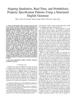
© Copyright 2026