Es
docs
Explorar
Iniciar sesión
Crear una nueva cuenta
Download
Report
Ingeniería
Point defects in ionic crystals
Praise for Love and Math
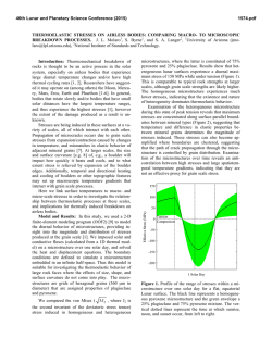
THERMOELASTIC STRESSES ON AIRLESS BODIES
ISTQB Foundations of Software Testing by Doroty Graham
Defects in Oscillatory Media: Toward a Classification
Vacant Positions
Programme
Ionization dynamics of simple metal clusters in intense fields by the
aupo 2015 program book
© Copyright 2026
Acerca de EsDocs
DMCA / GDPR
Alertar