
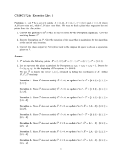
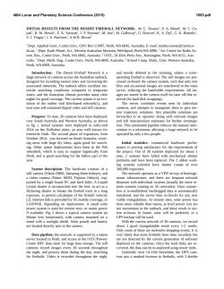
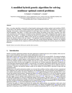
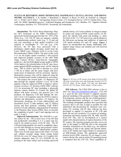
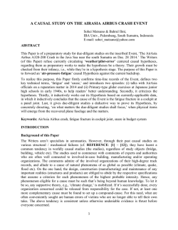
Motion Segmentation by New Three
Motion Segmentation by New Three-view Constrain from a Moving Camera Fuyuan Xu1, Guohua Gu1, Kan Ren1 and Weixian Qian1 Jiangsu Key laboratory of Spectral Imaging and Intelligent Sense, NanJing 210094, China Correspondence should be addressed to Fuyuan Xu; [email protected] Abstract: In this article, we propose a new method for the motion segmentation using a moving camera. The proposed method classifies each image pixel in the image sequence as the background or the motion regions by applying a novel three-view constraint called the “parallax-based multi-planar constraint”. This new three-view constraint, being the main contribution of this paper, is derived from the relative projective structure of two points in three different views and implemented within the “plane+parallax” framework. The parallax-based multi-planar constraint overcomes the problem of the previous geometry constraint and does not require the reference plane is constant across multiple views. Unlike the epipolar constraint, the parallax-based multi-planar constraint modifies the surface degradation to the line degradation to detect the motion objects followed by a moving camera in the same direction. We evaluate the proposed method with several video sequences to demonstrate the effectiveness and robustness of the parallax-based multi-planar constraint. Keywords: Motion segmentation, Parallax-based multi-planar constraint, Plane+parallax, Reference plane. 1 Introduction The ground motion detection is an essential challenge in many computer vision and video processing tasks, such as vision-based motion analysis, intelligent surveillance and regional defense. When the prior knowledge of the motion object appearance and shape is not available, the change detection or optical flow can still provide powerful motion-based cues for segmenting and localizing the objects, even when the objects move in a cluttered environment, or are partially occluded. The aim of the ground motion object detection is to segment the motion objects out according to the motions in the image sequence whether the platform is moving or not. For extensive study in detecting the motion objects in the image sequence captured by a moving camera, the scene contain multiple objects moving in the background and the background may also contain a strong parallax produced by the 3D structures. The motion segmentation in dynamic image background is inherently difficult, for the moving camera induces 2D motion for each pixel. The motion of pixels in moving objects is generated by both the independent object motion and the camera motion. In contrast, the motion of pixels in the static background is strictly due to the camera motion. Our goal is to utilize multi-view geometric constraints to segment the motion objects from the video sequence. The first geometric constraint used in detecting motion objects is the homography constraint in 2D plane mode [1-2]. The homography matrix is a global motion model which can compensate for the camera motion between consecutive images. The pixels which consistent with homography constraint is considered to belong to the static background [3]. However, those inconsistent pixels may correspond to the motion objects or parallax regions [4-5]. Because the homography constraint cannot distinguish the parallax regions and the moving objects, the epipolar constraint as the supplement of the homography constraint is used in the motion segmentation [6-7]. The epipolar constraint is a commonly used constraint for motion segmentation between two views [1, 8-9]. There are two corresponding feature points in two image from the different views. If a feature point in one image does not lie on the epipolar line induced by its matched the feature point in another image, then the corresponding 3D point will be determined to be moving [10]. However, the epipolar constraint is not sufficient to detect all kinds of 3D motion. Indeed, when the motion objects move on a special plane in 3D, then the epipolar constraint cannot detect them [1] .This phenomenon is called “surface degradation”. The 3D point moves on the epipolar plane which is formed by two camera centers of the different views and the point itself, so its 2D projections move along the epipolar lines. In this case, the motion objects cannot be detected by the epipolar constraint. The surface degradation often happens when the moving camera follows the objects moving along the same line. In order to overcome the surface degradation of the epipolar constraint, the geometric constraints over more than two views need to be imposed. The trilinear constraint can be applied to segment the motion objects across three views [1, 11]. However, estimating the parameters of the trifocal tensor is a nontrivial task, which requires accurate correspondence of the points and large camera motion. In this paper, inspired by the ref. 12, we propose a novel three-view constraint which named “parallax-based multi-planar constraint”. The parallax-based multi-planar constraint as the supplement of the epipolar constraint modifies the surface degradation to the line degradation. Compared the previous method based on the “Plane+Parallax” framework [12-15], the parallax-based multi-planar constraint can segment the motion objects without a fixed reference plane. The main contributions can be summarized as follows: (1) The parallax-based multi-planar constraint can segment the motion objects without a fixed reference plane. The traditional methods [13, 14, 15] assume that the reference plane is consistent across three views. However, this assumption is not valid in sometimes. The parallax-based multi-planar constraint is inspired by ref. 12 and segment the motion object without a fixed reference plane based on “Plane+Parallax” framework. This is the main contribution in this paper. (2) A reference point is introduced to replace the epipole. The calculation of the epipole is inaccurate when the motion vectors of the feature points are followed by a moving camera in the same direction [13]. The reference point can improve the accuracy of the parameters to get better results for the motion segmentation. (3) A motion segmentation framework based on the parallax-based multi-planar constraint is proposed. In the motion segmentation framework, the parallax-based multi-planar constraint and the homography constraint are applied in the “plane+parallax” framework. This motion segmentation framework can reduce the run time and apply the parallax-based multi-planar constraint into real-time system. The paper is organized as follows. In Section 2, we briefly review the existing approaches related to our work. Section 3 formally describes the epipolar constraint and the surface degradation that the epipolar constraint is unable to handle. In Section 4, we briefly review the definition of the parallax-based rigidity constraint in ref. 12. We then introduce the parallax-based multi-planar constraint and its degenerate cases in Section 5. The application of the parallax-based multi-planar constraint is explained in Section 6. The experimental results are shown and discussed in Section 7. Section 8 concludes our paper and presents possible directions for future research. 2 Related Work From described in Section 1, the methods of the motion objects detection from a moving camera are vast. The parallax-based multi-planar constraint is based on “plane+parallax” framework to segment the motion objects. It consider that the image sequence can be decomposed into the reference plane, the parallax and the motion objects. Thus, the motion segmentation methods based on the background subtraction and the motion segmentation with the strong parallax are the most related topics to this paper. The background subtraction method has a wide range of applications in the static camera [14]. A novel framework to segment the motion objects by detecting contiguous outliers in the low-rank representation is proposed in [4, 15]. It avoids the complicated motion computation by formulating the problem as outlier detection and makes use of the low-rank modeling to deal with complex background. A new method based on Dirichlet process Gaussian mixture models, which are used to estimate per-pixel background distributions. It is followed by the probabilistic regularization. Using a non-parametric bayesian method allows per-pixel mode counts to be automatically inferred, avoiding over-/under- fitting [16]. These methods have get better effect for the image sequence without the strong parallax. For motion segmentation with the strong parallax, a sparse motion field estimation is a common approach [17, 18]. The sparse motion field of the corners is recovered and the corners that belong to the same motion pattern are classified according to their motion consistency [17, 19, 20]. The constraint equations are be applied in the optical flow to decompose the background and foreground [21]. An effective approach to do background subtraction for complex videos by decomposing the motion trajectory matrix into a low rank one and a group sparsity one. Then the information from these trajectories is used to further label foreground at the pixel level [22].The motion segmentation approaches [23] segment the point trajectories based on subspace analysis. These algorithms provide interesting analysis on sparse trajectories, though do not output a binary mask as many background subtraction methods do. However, most of the methods based on sparse motion field estimation assume that the motion object can be represent by the feature points (example as Harris corners). This assumption is invalid in many cases, so the detect rate is poor for these method. 3 Epipolar Constraint and Surface Degradation The epipolar geometry is the intrinsic projective geometry between two views. It is independent of the scene structure, and only depends on the cameras’ internal parameters and relative pose of the camera. The epipolar constraint is usually used in the motion segmentation in two views. The fundamental matrix is the algebraic representation of epipolar geometry [1, 8]. Suppose that there are two images acquired by cameras with non-coincident centers, then the fundamental matrix F21 is the homogeneous matrix between the view 1 and view 2 which satisfies: p2T F21 p1 0 , (1) for all corresponding points p1 and p2 . If P is a 3D static point, p1 and p2 are the projection of P in the image 1 and the image 2 which are from the view 1 and the view 2. If the point P moves between the view 1 and view 2, the position of the 3D point P in the view 2 is denoted as P , the epipolar line is p2 is therefore the projection of the point P in the image 2 and l2 F21T p2 . In this case, p1 does not lie on l1 and p2 does not lie on l2 F21 p1 . The pixel-to-line distance d epi is used to measure how the point pair deviates from the epipolar lines depi l1 p1 l2 p2 / 2 (2) where l1 p1 and l2 p2 are the perpendicular distances from p1 to l1 and from p2 to l2 , respectively, and as shown in Figure. 1(a). d epi is used to detect whether the 3D point P is moving or not. If Furthermore, depi 0 , P is moving. However, there is a special kind case, called “surface degradation”, that the moving points cannot be detected by the epipolar constraint. The surface degradation happens when the objects moving in a special plane, as illustrated in Figure. 1(b). if the point P , the camera centers C1 and C2 constitute a plane in 3D Euclidean space and the point P moves to P and In this situation, P , the point p2 lie on l2 and the point p1 lie on l1 in 2D images. depi 0 and the surface degradation happen. P P P p1 l1 p2 p2 l2 p1 C1 e1 e2 View 1 View 2 (a) C2 P P P p2 l1 p1 p2 p1 e1 C1 e2 l2 C2 View 2 View 1 (b) Figure 1: Application of the epipolar constraint. (a) Motion object detected by the epipolar constraint. (b) Surface degradation: Motion object moving on the plane. Unfortunately, there are many practical that the camera follows the motion objects moving in the same direction [12, 24]. If the camera follows the objects moving in the same direction, the surface degradation may happen. In order to solve the surface degradation, multi-view constraints need to be introduced. Therefore, in the following Section 4 and Section 5, the novel three-view constraints are proposed to segment the motion object. 4 Parallax-Based Rigidity Constraint The “Plane + Parallax” framework [12, 15, 25] extends the 2D parametric registration approach to general 3D scenes. The plane registration process (using the dominant 2D parametric transformation) removes all effects of camera rotation, zoom, and calibration, without explicitly computing them. The residual image motion after the plane registration is only due to the translational motion of the camera and to the deviations of the scene structure from the planar surface. 4.1 “Plane + Parallax” Framework Figure. 2 provides the geometric interpretation of the “planar parallax” framework. Let P X , Y , Z denote a 3D static point and P1 X 1 , Y 1 , Z 1 T and P X , Y , Z 2 2 2 2 T denote the coordinates of P in different camera views. Let the 3 3 rotation matrix R and the 3 1 translation vector T = TX , TY , TZ denote the rotation and translation between the camera systems. Let x , y 1 1 and x , y 2 2 denote the image coordinates of the 3D point P projected onto two different views. The homogeneous expression can be denoted as p x , y ,1 1 1 1 T and p 2 x 2 , y 2 ,1 . Let be an arbitrary planar surface and P . A denote the T homography matrix that aligns the planar surface between two different views. We can describe as p1 Ap 2 [1]. Define J p p u, v,0 2 1 T , where u, v is the 2D image displacement vector of the 3D point P between two different views. It can be shown as well as, that J J J 1 (3) where J denote the planar part of the 2D image motion and J denote the residual planar parallax 2D motion. When TZ 0 : J p 2 p1 ; J 1 1 Tz 1 e p1 2 d (4) 1 where p denotes the in the view 1 which results from warping the corresponding p 2 in the view 2, by the 2D parametric transformation of the reference plane . The first view is referred as the reference view. Also, d 2 is the perpendicular distance from the second camera center to the reference plane , and noted e1 denotes the epipole. 1 is measure of the 3D shape of the H , where H is the perpendicular distance from the P to Z1 the reference plane , and Z 1 is Z -distance of the point P in the first camera coordinate 3D point P . In particular, 1 systems. We refer 1 to the projective 3D structure of the point P . The use of the “plane + parallax” framework for ego-motion estimation is described in [12], and for 3D shape recovery is described in [26]. The “plane + parallax” framework is more general than the traditional decomposition in terms of rotational and translational motion. P / P1 / P 2 H P View 1 View 2 1 p1 p R, T p2 e1 C2 C1 Figure 2: Geometric interpretation of the “planar+parallax” framework 4.2 Parallax-Based Rigidity Constraint 1 1 Theorem 1. Give the planar-parallax displacement vectors J j and J r of two points that belong to the static background scene, their relative 3D projective structure 1j is given by r1 1j J j p r1 J 1 T p1 j r 1 T 1 (5) 1 where as shown in Figure. 3(a), p j and p1r are the image locations of two points that are part of the static scene, p p , j p ,r , the vector connect the “warped” locations of the 1 1 1 corresponding another view points, and v signifies a vector perpendicular to v [12]. 1j J j p AB Form Figure 3(a), 1 when the epipole is stable. However, when r J 1 T p1 j AC r 1 T 1 the parallax vectors are nearly parallel, the epipole estimation is unreliable. However, the relative structure AB can be reliably computed in this case (see Figure. 3(b)). AC p1 , j J 1j 1 j p1j p p1 e1 J 1j p1 e1 p1r J r1 1 r p J r1 C A p1 ,r p1 , j C A p1 ,r B B (a) (b) Figure. 3. Pairwise parallax-based shape constraint. (a) Interpretation of the relative structure constraint.(b) When the parallax vectors are nearly parallel, the epipole estimation is unreliable. Theorem 1 is called “parallax-based shape constraint” proved in [12] and it is noted that this constraint directly relates the relative projective structure of two points to their parallax displacements alone: no camera parameters, in particular the epipole (FOE) which is difficult to calculate accurately [27-29]. This is different from the traditional methods use the two parallax vectors to recover the epipole and then use the magnitudes and distances of the points from the computed epipole to estimate their relative projective structure. The benefit of the constraint (Equation. 5) is that it provides this information directly from the positions and parallax vectors of the two points, without the need to go through the computation of the epipole [12]. Theorem 2. Given the planar-parallax displacement vectors of two points that belong to the background static scene over the view 1, view 2 and view 3, the following constraint must be satisfied: J p J p J p J p 1 j 1 r T 1 1 j T 2 j 2 r T T 2 0 (6) 2 1 where J 1j , J r are the parallax displacement vectors of the two points between the reference 2 plane and the view 1. J 2j , J r are the parallax vectors between the reference plane and the view 2, and p1 , p2 are the corresponding distances between the warped points [12]. In the case of the parallax-based shape constraint, the parallax-based rigidity constraint (Theorem 2) relates the parallax vectors of the pairs of points over three views without referring to any camera parameters. However, the parallax-based rigidity constraint assumes that the reference plane is consistent across three views. This assumption is not valid in sometimes, since the interframe homographies are automatically estimated and the reference planes may correspond to different parts of the scene. 5 Parallax-Based Multi-planar Constraint In this work, we propose a novel three-view constraint, which is called the “parallax-based multi-planar constraint”. This constraint is capable of detecting the motion object that the epipolar constraint cannot detect without a fixed the reference plane across three views. 5.1 Description of the Parallax-Based Multi-planar Constraint 1 2 Theorem 3. The image points p j and p j given in view 1 and view 2 which are projected by the 3D point P which belonging to the background, they must all satisfy the following constraint: 2 pj where p1 j 2j 1 0 N r2 44 1j r (7) 1j 2j is the relative projective structure for view 1 to view 2 and is the relative r1 r2 projective structure for view 2 to view 3. N is a 4 4 matrix. (Proof. See Appendix A) Theorem 3 is called “parallax-based multi-planar constraint”. The parallax-based multi-planar constraint represents a constraint for the same point in the background by their relative 3D projective structure. This constraint can detect the moving objects from the moving camera without a fixed the reference plane across three views. Its degenerate case is modified from the surface degradation to the line degradation (it is discussed in Section 5.2). 5.2 Degradation of the Parallax-Based Multi-planar Constraint The parallax-based multi-planar constraint uses the relative 3D projective structure from three views to detect the moving objects. This constraint is capable of detecting most of the degenerate cases mentioned in this paper. However, there still exists a degenerate case that cannot be detected. Result 1. Given a 3D moving point P and its Z -distance in camera coordinate systems at time i | i 1, 2,3 is equal. The parallax-based multi-planar constraint cannot detect this moving point. (Proof. See Appendix B) The Figure. 4 is show the degenerate case for parallax-based multi-planar constraint. Fortunately, these cases happen much less frequently in reality, because the proportional relationship is not easily satisfied. P2 P1 P3 Z1 Z 2 Z 3 Z1 Z3 Z2 View 1 View 3 View 2 C3 C1 C2 Figure 4: Degenerate case for parallax-based multi-planar constraint. 6. Application of the Parallax-Based Multi-planar Constraint In this section, we present some implementation details of a detecting and tracking moving objects system based on the parallax-based multi-planar constraint. As shown in Figure. 5, the system is built as a pipeline of five stages: feature point matching, plane segmentation, dense optical flow, object extraction and spatio-temporal tracking. Original Video Homography Parameter Estimation Feature Point Matching Plane Segmentation Parallax-Based Multi-planar Constraint Parameter Estimation Dense Optical Flow Object Extraction Spatio-temporal Tracking Figure 5: Pipeline of the detecting the motion object This system starts with the feature point matching. Then, the homography parameters and the parallax-based multi-planar constraint parameters are estimated by the feature points matching. We can get the plane residual image which is composed of the pixels which are not satisfied for the homography constraint. The motion field of the binary of the plane residual image can be obtained by the dense optical flow. The parallax-based multi-planar constraint can distinguish the parallax pixels and motion pixels from the plane residual image. Finally, the 2D motion pixels obtained from each frame are linked into motion trajectories by a spatio-temporal tracking algorithm. The Kanade-Lucas-Tomasi(KLT) feature tracking [30-32] is applied to extract and track feature points in the image sequence I t i | i , 0, . is the temporal window size. The homography parameters can be estimated by the method described in ref. 1. I t i can be warped to the It by the homography matrix. Then, after estimating the background model [33-34] (we use the single gauss algorithm in this work), we obtain the binary image of the plane residual image which is composed by the pixels with intensity differences larger than the threshold Thhom . We chose the three image ( I t , I t and I t , is the time interval) from the image sequence and estimate parallax-based multi-planar constraint parameters by the corresponding feature points. The parallax-based multi-planar constraint parameters are estimated by the similar method of estimating the fundamental matrix [1]. N is obtained by singular value decomposition. The random sample consensus (RANSAC) scheme is a common choice, which finds a solution with the largest inlier support [1]. The motion field of the pixel in the binary image of the plane residual image can be acquired by the dense optical flow in refs. 31 and 32. We define an algebraic error function through the Equation. 7. d parallax when p 2j p1j 2j N 44 1j 2 r 1 r (8) d parallax thpara , this pixel is in the motion region. On the contrary ( d parallax thpara ), the pixel is in parallax region. thpara is a parallax threshold. So we can extract the motion object from the plane residual image and get the motion binary image. The motion binary images are further refined by standard morphological operations such as erosion and dilation. The connected pixels are grouped into compact motion regions, whereas scattered pixels are removed. The tracking step takes image appearance, 2D motion vectors, and motion likelihood of these regions as its observation and link similar regions into object trajectories. Since the object tracking is not the focus of this paper, interested readers can refer to Refs. 35 and 36. 7 Experiment and Analysis In this section, we present the experimental results obtained by a number of video sequences. In all the video sequences, the camera undergoes general rotation and translation. Both the qualitative and quantitative results demonstrate the effectiveness and robustness of our method. 7.1 Qualitative Evaluation There are five video sequences have been adopted to qualitatively demonstrate the effectiveness and robustness of the parallax-based multi-planar constraint. In Figure. 6, we show the segmenting results of a video sequence which is captured in the laboratory. We use checkerboard pattern only have black and white checks to compose the background of the video and a cylindrical object as a motion object. So, we can call this video “chessboard”. This background can ensure that there are enough feature points (Harris corners is accepted in this paper) in it. The video is captured by a moving gray camera; the resolution of the video is 315 235 ; the frame frequency is 25fps. In this paper, the parameters 40 , Thhom 0.2 and 5, thpara 0.75 . We show the three frames image (#148, #153 and #158) in the video sequence which are shown in Figures. 6(a), (b) and (c) and the red points are defined as the reference points. The camera translate from the left to right. In this video sequence the reference plane is the checkerboard. There are two static objects as the parallax regions. After computed by 2D registration [1], the parallax and motion regions is obtained from the plane residual image which is shown in Figure 6(d). As can be seen in Figure. 6(d), the two parallax regions are clear. Figure. 6(e) is the residual image of the parallax-based multi-planar constraint. The intensity of the motion region is greater than the other region whether include or not the parallax region. In Figure 6(f), it is the binary result of the residual image of the parallax-based multi-planar constraint and shown that the parallax regions (the two static objects) are eliminated finally. (a) (b) (c) (d) (e) (f) Figure 6: Motion segmentation result of the “chessboard”. (a) Original image of the frame 148. (b) Original image of the frame 153. (c) Original image of the frame 158. (d) Plane residual image. (e) Residual image of the parallax-based multi-planar constraint. (f) Binary result of the parallax-based multi-planar constraint. The second video sequence is the experiment video of ref. 12 and is named “car 1”. Its resolution is 320 240 ; the frame frequency is 25fps. In this paper, the parameters 12 , 3 , Thhom 0.31 and thpara 0.68 . Figure 7(a) is the original image (#17) and the red points are defined as the reference points. In this sequence the camera is in motion (translating from the left to right), inducing parallax motion of different magnitudes on the house, road, and road sign. The car moves independently from the left to right. Figure 7(b) is the plane residual image and Figure 7(c) is the binary result of the plane residual image. Because the car is followed by a moving camera in the same direction, the surface degradation of the epipolar constraint is happened and shown in Figure 7(d). Figure 7(e) is the residual of the parallax-based multi-planar constraint computed over three fame. The final binary result is shown in Figure 7(f). From figure 7, the parallax-based multi-planar constraint modifies the surface degradation to the line degradation to segment motion objects followed by a moving camera in the same direction. (a) (b) (c) (d) (e) (f) Figure 7: Motion segmentation result of the “car 1”. (a) Original image of the frame 17. (b) Plane residual image. (c) Binary result of the plane residual image. (d) Residual image of the epipolar constraint. (e) Residual image of the parallax-based multi-planar constraint. (f) Binary result of the parallax-based multi-planar constraint. Figure 8 is shown that a camera move from the left to right and there is a car move from the right to left. We can call it “car 2”. This video is capture by a gray camera. Its resolution is 315 235 ; the frame frequency is 25fps. In this paper, the parameters 40 , 2 , Thhom 0.2 and thpara 0.8 . In this video sequences, three frame images (#19, #21 and #23) are shown in Figures 8(a), (b) and (c) and the red points are defined as the reference points. In Figures 8(a) and (b), the green points is the corner points which are the inner points for reference plane between frame 19 and 21. In Figures 8(b) and (c), the blue points is the corner points which are the inner points for reference plane between frame 21 and 23. So, the reference plane is changed from frame 19 to 23. Figure 8(d) is the plane residual image. The motion region cannot segment from the background by the residual image of the parallax-based rigidity constraint which is shown in Figure 8(e), because of the change of the reference plane. Figure 8(f) is the residual image of the parallax-based multi-planar constraint. From Figure 8, the parallax-based multi-planar constraint can obtained a better effect compere with the parallax-based rigidity constraint, because it does not need a fixed reference plane over three frame. (a) (b) (c) (d) (e) (f) Figure 8: Motion segmentation result of the “car 2”. (a) Original image of the frame 19. (b) Original image of the frame 21. (c) Original image of the frame 23. (d) Plane residual image. (e) Residual image of the parallax-based rigidity constraint. (f) Residual image of the parallax-based multi-planar constraint. Figure 9 is an infrared video acquired from the VIVID dataset. Its resolution is 310 246 ; the frame frequency is 30fps. In this paper, the parameters 30 , 3 , Thhom 0.2 and thpara 0.82 . The camera is in unmanned aerial vehicle. There are three cars move on the road. So, we can call it as “cars 1”. The building is considered as the parallax region. The first row is the original images from 71 to 77 and the red points are defined as the reference points. The second row is the plane residual images. The third row is the residual of the parallax-based multi-planar constraint. The final binary results are shown in the fourth row. We demonstrate the potential of the parallax-based multi-planar constraint applied to the motion segmentation problems using the Berkeley motion segmentation dataset in Figure 10. In this video, there is a car move on the road and the camera move from the right to left. It is called as “car 4”. Its resolution is 320 240 ; the frame frequency is 30fps. In this paper, the parameters 30 , 2 , Thhom 0.32 and thpara 0.74 . The first row is the original images from 13 to 17 and the red points are defined as the reference points. The second row is the plane residual images. The third row is the residual of the parallax-based multi-planar constraint. The final binary results are shown in the fourth row. Figure 9: Motion segmentation result of “cars 1” Figure 10: Motion segmentation result of “car 3” From all of the above experiments, we can know that the parallax-based multi-planar constraint can segment the motion regions from the “moving” background. First of all, compared with the homography constraint, the parallax-based multi-planar constraint can segment the parallax regions and the motion regions. Secondly, the parallax-based multi-planar constraint modifies the surface degradation of the epipolar constraint to the line degradation and can detect the motion object followed the direction of the camera move. Thirdly, in the process of motion segmentation, the parallax-based multi-planar constraint needs not a fixed reference plane across three views. Therefore, this method can effective extract the motion object from a moving camera and this camera is uncalibrated. 7.2 Quantitatively Evaluation In order to quantitatively evaluate the performance of our system, we have manually labeled the ground-truth data on the above video sequences. The ground-truth data refer to a number of 2D polygons in each video frame, which approximate the contour of motion regions. For the “chessboard” and “car 2” video, there are 20 frames labeled in different parts. Based on the ground-truth and detected motion mask images, we define two area-based metrics to evaluate our method [37]. Let g denote the set of pixels that belong to the t ground-truth motion regions in the frame t and td denote the set of the actually detected pixels in the frame t . We define a detection rate to evaluate how many detected pixels lie in the ground-truth motion regions as R t N td tg N tg (9) and a precision rate to evaluate how many detected pixels are indeed motion pixels as P t 1 N td tg N td (10) where is the complement set of and N is the number of pixels within . In this, R t 0,1 and P t 0,1 . The higher both measures are, the better the performance of motion segmentation becomes. The detection rate and the precision rate measures are computed over the labeled video frames to evaluate the performance of our motion segmentation method. For the “chessboard” and “car 1” videos, we evaluate three moving segmentation method: epipolar constraint [1], parallax-based rigidity constraint [12], Detecting contiguous outliers in the low-rank Representation (DECOLOR) [4] and our method. The first line and the third line of Figure. 11 are the ground-truth data; the second line and fourth line are the motion segmentation results of the parallax-based multi-planar constraint for the “chessboard” video. The red points are defined as the reference points. Figure 11: the ground-truth data and the motion segmentation results of the parallax-based multi-planar constraint for the “chessboard” video. Let us quantitatively compare the performance of the methods based on the curves of the detection rate and precision rate. The detection rate of the epipolar constraint is low compared with the other methods in Figure. 12(a) for the surface degradation. The DECOLOR method is based on the homography constraint so that the parallax regions and the motion regions are considered as “motion objects”. Its precision rate is lower than the other methods in Figure 12(b). In Figure 12, the parallax-based multi-planar overcome the surface degradation of the epipolar constraint. It can get good effect in the detection rate and the precision rate. (a) (b) Figure 12: Quantitative evaluation results for “chessboard” video. (a) Curve of the detection rate. (b) Curve of the precision rate. Figure 13 is the ground-truth data and the motion segmentation results of the parallax-based multi-planar constraint for “car 2” video which is similar to Figure 11. In Figure 13, when the reference planar is changed from frame 262 to 264, there are a lot of false alarm detected by the parallax-based rigidity constraint and DECOLOR which has shown in Figure 14(b). In contrast, the parallax-based multi-planar constraint segment the motion objects without a fixed reference plane, so it performs better in precision rate. Figure 13: the ground-truth data and the motion segmentation results of the parallax-based multi-planar constraint for “car 2” video. (a) (b) Figure 14: Quantitative evaluation results for “car 2” video. (a) Curve of the detection rate. (b) Curve of the precision rate. 7.3 Parameter Selection There are a few parameters that are found to be critical for system performance. The first important measure, that is the temporal window size . This parameter is used by the homograph image registration to get the plane background. relate to the frame frequency and the size of camera motion. If is set too small, the detect rate may decline. On the contrary, if it is set too big, the overlap region is too small to do not detect the motion object and the false-alarm probability may increase for the accumulated errors. is proportional to the frame frequency and inversely proportional to the size of camera motion. The second one, that is the time interval , is used for the estimation of the parallax-based multi-planar constraint parameters. also relate to the frame frequency and the size of camera motion. If the different of continuous image is rather small, needs to be increased for a stable estimation of the parallax-based multi-planar constraint parameters. The third parameter is the homograph threshold sure that there enough pixels to compute the Thhom . Thhom is set at low value to make d parallax . This threshold needs to be adjusted to different scene configurations in order to include all the possible motion pixels and enough parallax pixels as well. However, if Thhom is set too small, the run time may increase. The fourth parameter is the parallax threshold parallax distance thpara . This parameter is used to segment the d parallax to detect the motion objects. thpara relate to the time interval and is proportional to it. 8 Conclusion We have presented a novel method for detecting moving objects in video sequences captured from a moving cameras. It uses the multi-view geometric constraints for motion detection in three or multiple views. Moreover, the parallax-based multi-planar constraint this paper proposed overcomes the problem of the previous geometry constraint and does not require the reference plane to constant across multiple views and modifies the surface degradation of the epipolar constraint to the line degradation. It can detect the motion objects followed by a moving camera in the same direction. The experimental results demonstrate the effectiveness and robustness of our approach. There are several doable directions for future work to be carried out. An appropriate reference point can be fined for computing the parallax. If the camera projection matrices are known or obtained by the self-calibration techniques [1], then both the static background and the moving objects can be reconstructed and aligned together in the 3D Euclidean space. Acknowledgments This project is supported by the Natural Science Foundation of Jiangsu Province of China, under Grant no. BK20130769, Jiangsu Province High-level Talents in Six Industries no.2012-DZXX-037 and Program for New Century Excellent Talents in University no. NCET-12-0630. Appendix A In this appendix, we prove Theorem. 3, we derive Equation. 7. Let Pj X j , Y j , Z j be a 3D static point and its 3D coordinates in the view 1, view 2 and view 3 are expressed Pj X j , Yj , Z j , Pj X j , Yj , Z j 1 1 1 1 2 2 2 2 and Pj X j , Yj , Z j . There 3 3 3 3 is another 3D static point Pr X r , Yr , Z r as the reference point and its 3D coordinates are expressed in three views Pr X r , Yr , Zr , Pr X r , Yr , Zr 1 1 1 1 2 2 2 2 and Pr X r , Yr , Zr . 3 3 3 3 p1j , p 2j and p 3j of the 3D point Pj is the homogeneous image coordinates in the image 1, image 2 and image 3 and p1r , pr2 and pr3 of the 3D point Pr is the homogeneous image coordinates in the image 1, image 2 and image 3, respectively. From the Section 4,for the view 1 and view 2, we know that the 3D projective structure of the point Pj and the 3D projective structure of the point Pr are 1 j H 1j Z 1j ; r1 H r1 , Z r1 (11) Because the point Pr is reference point, the 3D projective structure of the point invariant for all image points. We can define the r1 =1 and 1 r1 is an is a constant factor for the other points. From Equation. 11, we can know that 1j H 1j Z r1 H 1j r1 Z 1j H r1 1Z 1j (12) H 1j v1T Pj1 1 (13) 1 For the 3D point Pj : Where v1 is the normal vector of plane scaled by distance from the camera center of view 1 to the reference plane Substituting Equation. 13 in Equation. 12 obtains 1j v1T Pj1 1 r1 1Z 1j 1/ d . d is the perpendicular . (14) The camera model can be represented as Z 1j K 1 p1j Pj1 (15) Substituting Equation.15 in Equation. 14 obtains j 1 v1T K 1 p1j 1 1 1 Zj r 1 Similarly, we can get the (16) j 1 v2T K 1 p 2j 2 2 2 Zj r 2 (17) for view 2 and view 3. Let r2,1 denote the third row of rotation matrix R2,1 and t2,1 denote third component of translation vector T2,1 . The 3D depth of point Pj1 could be related to that of Pj2 by extracting the third row in Pj R2,1Pj T2,1 as 2 1 Z 2j r2,1Pj1 t2,1 (18) Substituting Equation. 15 into Equation. 18, we have r2,1 K 1 p1j t 1 12,1 2 1 2 Zj Zj Z jZ j (19) Substituting Equation. 16 and Equation. 17 into Equation. 19,we can obtain v1T K 1 p1j 1 1j r1 (20) T 1 2 2j 1j T 1 1 v2 K p j 2 2 r2,1 t2,1v1 K p j t2,11 1 r r By rewriting the Equation. 20, we have 2 pj 2 j 2 r 0 p1j 0 T 1 1 1j v1 K 1 1 r 0 p t2,11 1j 1 r 2j v2T K 1 T r t v r2 2 2,1 2,1 1 2 pj (21) 1 j So we can get the parallax-based multi-planar constraint 2 pj p1j 2j N 44 1j 0 2 r 1 r (22) Appendix B In this appendix, we prove Result 1 by the algebraic approach, we describe the degradation of the parallax-based multi-planar constraint. Let Pj X j , Yj , Z j , Pj X j , Yj , Z j 1 1 1 1 2 2 2 2 and Pj X j , Yj , Z j 3 3 3 3 denote the 3D corresponding points in the three views. Assume Z j Z j Z j and according to the Equation. 1 2 3 16 and Equation. 17, we can get v2T K 1 p 2j 2 2j 1j T 1 1 v K p j 1 1 r2 1 r (23) Substituting into Equation. 20,we can eliminate the left polynomial: 1j T 1 1 1 r2,1 t2,1v1 K p j t2,11 1 r (24) decompose Equation. 24 , we can get Z 1j r2,1Pj1 t2,1 (25) because Z j Z j Z j , the Equation. 25 is identities. We can derive the degradation of the 1 2 3 parallax-based multi-planar constraint is that the parallax-based multi-planar constraint cannot detect the motion object when the Z -distance of the 3D point in camera coordinate systems at time i | i 1, 2,3 is equal ( Z j Z j Z j ). 1 2 3 References [1] Hartley R, Zisserman A. Multiple view geometry in computer vision[M]. Cambridge university press, 2003. [2] Ayer S, Sawhney H S. Layered representation of motion video using robust maximum-likelihood estimation of mixture models and MDL encoding[C]. Computer Vision, 1995. Proceedings., Fifth International Conference on. IEEE, 1995: 777-784. [3] Kim S W, Yun K, Yi K M, et al. Detection of moving objects with a moving camera using non-panoramic background model[J]. Machine vision and applications, 2013, 24(5): 1015-1028. [4] Zhou X, Yang C, Yu W. Moving object detection by detecting contiguous outliers in the low-rank representation[J]. Pattern Analysis and Machine Intelligence, IEEE Transactions on, 2013, 35(3): 597-610. [5] Kang J, Cohen I, Medioni G. Continuous tracking within and across camera streams[C] Computer Vision and Pattern Recognition, 2003. Proceedings. 2003 IEEE Computer Society Conference on. IEEE, 2003, 1: I-267-I-272 vol. 1. [6] Bergen J R, Burt P J, Hingorani R, et al. A three-frame algorithm for estimating two-component image motion[J]. IEEE Transactions on Pattern Analysis and Machine Intelligence, 1992, 14(9): 886-896. [7] Darrell T, Pentland A. Robust estimation of a multi-layered motion representation[C] Visual Motion, 1991., Proceedings of the IEEE Workshop on. IEEE, 1991: 173-178. [8] Micusik B, Pajdla T. Estimation of omnidirectional camera model from epipolar geometry[C] Computer Vision and Pattern Recognition, 2003. Proceedings. 2003 IEEE Computer Society Conference on. IEEE, 2003, 1: I-485-I-490 vol. 1. [9] Zhang Z, Deriche R, Faugeras O, et al. A robust technique for matching two uncalibrated images through the recovery of the unknown epipolar geometry[J]. Artificial intelligence, 1995, 78(1): 87-119. [10] Thompson W B, Pong T C. Detecting moving objects[J]. International journal of computer vision, 1990, 4(1): 39-57. [11] Hartley R, Vidal R. The multibody trifocal tensor: Motion segmentation from 3 perspective views[C] Computer Vision and Pattern Recognition, 2004. CVPR 2004. Proceedings of the 2004 IEEE Computer Society Conference on. IEEE, 2004, 1: I-769-I-775 Vol. 1. [12] Irani M, Anandan P. A unified approach to moving object detection in 2D and 3D scenes[J]. Pattern Analysis and Machine Intelligence, IEEE Transactions on, 1998, 20(6): 577-589. [13] Dey S, Reilly V, Saleemi I, et al. Detection of independently moving objects in non-planar scenes via multi-frame monocular epipolar constraint[M]. Computer Vision–ECCV 2012. Springer Berlin Heidelberg, 2012: 860-873.. [14] Sajid H, Cheung S C S. Background subtraction under sudden illumination change[C]//Multimedia Signal Processing (MMSP), 2014 IEEE 16th International Workshop on. IEEE, 2014: 1-6. [15] Szolgay D, Benois-Pineau J, Mégret R, et al. Detection of moving foreground objects in videos with strong camera motion[J]. Pattern Analysis and Applications, 2011, 14(3): 311-328. [16] Haines T, Xiang T. Background Subtraction with Dirichlet Process Mixture Models[J]. 2014. [17] Zhang H, Yuan H, Li J. Moving object detection in complex background for a moving camera[C]//Fifth International Conference on Machine Vision (ICMV 12). International Society for Optics and Photonics, 2013: 87831I-87831I-8. [18] Wan Y, Wang X, Hu H. Automatic Moving Object Segmentation for Freely Moving Cameras [J]. Mathematical Problems in Engineering, 2014, 2014. [19] Sun S W, Wang Y C F, Huang F, et al. Moving foreground object detection via robust SIFT trajectories [J]. Journal of Visual Communication and Image Representation, 2013, 24(3): 232-243. [20] Ren Z, Chia L T, Rajan D, et al. Background subtraction via coherent trajectory decomposition[C]//Proceedings of the 21st ACM international conference on Multimedia. ACM, 2013: 545-548. [21] Sawhney H S, Guo Y, Asmuth J, et al. Independent motion detection in 3D scenes[C] Computer Vision, 1999. The Proceedings of the Seventh IEEE International Conference on. IEEE, 1999, 1: 612-619. [22] Cui X, Huang J, Zhang S, et al. Background subtraction using low rank and group sparsity constraints[M]//Computer Vision–ECCV 2012. Springer Berlin Heidelberg, 2012: 612-625. [23] Rao S, Tron R, Vidal R, et al. Motion segmentation in the presence of outlying, incomplete, or corrupted trajectories[J]. Pattern Analysis and Machine Intelligence, IEEE Transactions on, 2010, 32(10): 1832-1845. [24] Torr P H S, Murray D W. Outlier detection and motion segmentation[C] Optical Tools for Manufacturing and Advanced Automation. International Society for Optics and Photonics, 1993: 432-443. [25] Lourakis M I A, Argyros A A, Orphanoudakis S C. Independent 3D motion detection using residual parallax normal flow fields[C] Computer Vision, 1998. Sixth International Conference on. IEEE, 1998: 1012-1017. [26] Irani M, Anandan P. Parallax geometry of pairs of points for 3d scene analysis[M] Computer Vision—ECCV'96. Springer Berlin Heidelberg, 1996: 17-30. [27] Kumar R, Anandan P, Hanna K. Direct recovery of shape from multiple views: A parallax based approach[C] Pattern Recognition, 1994. Vol. 1-Conference A: Computer Vision & Image Processing., Proceedings of the 12th IAPR International Conference on. IEEE, 1994, 1: 685-688. [28] Chen Z, Wu C, Shen P, et al. A robust algorithm to estimate the fundamental matrix[J]. Pattern Recognition Letters, 2000, 21(9): 851-861. [29] Migita T, Shakunaga T. One-dimensional search for reliable epipole estimation[M]//Advances in Image and Video Technology. Springer Berlin Heidelberg, 2006: 1215-1224. [30] Lucas B D, Kanade T. An iterative image registration technique with an application to stereo vision[C] IJCAI. 1981, 81: 674-679. [31] Tomasi C, Kanade T. Detection and tracking of point features[M]. Pittsburgh: School of Computer Science, Carnegie Mellon Univ., 1991. [32] Shi J, Tomasi C. Good features to track[C] Computer Vision and Pattern Recognition, 1994. Proceedings CVPR'94., 1994 IEEE Computer Society Conference on. IEEE, 1994: 593-600. [33] Lee D S. Effective Gaussian mixture learning for video background subtraction[J]. Pattern Analysis and Machine Intelligence, IEEE Transactions on, 2005, 27(5): 827-832. [34] Zivkovic Z, van der Heijden F. Efficient adaptive density estimation per image pixel for the task of background subtraction[J]. Pattern recognition letters, 2006, 27(7): 773-780. [35] Huang J, Abendschein D, Dávila-Román V G, et al. Spatio-temporal tracking of myocardial deformations with a 4-D B-spline model from tagged MRI[J]. Medical Imaging, IEEE Transactions on, 1999, 18(10): 957-972. [36] Zhang C, Chen S C, Shyu M L, et al. Adaptive background learning for vehicle detection and spatio-temporal tracking[C] Information, Communications and Signal Processing, 2003 and Fourth Pacific Rim Conference on Multimedia. Proceedings of the 2003 Joint Conference of the Fourth International Conference on. IEEE, 2003, 2: 797-801. [37] Nascimento J C, Marques J S. Performance evaluation of object detection algorithms for video surveillance[J]. Multimedia, IEEE Transactions on, 2006, 8(4): 761-774.

© Copyright 2026