
TOSHIBA Carrier (UK) Ltd. LC DX Interface Installation manual
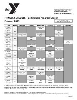
TOSHIBA Carrier (UK) Ltd. LC DX Interface Installation manual For commercial use Model name: RAV-DXC010 LC DX Interface ENGLISH LC DX Interface Installation Manual Please read this Installation Manual carefully before installing the LC DX interface. This Manual describes the installation method of the LC DX interface. You must also refer to the Installation Manual attached to the Toshiba outdoor unit. Please follow the manual(s) for your Air Handling Unit (local supply). Toshiba Carrier UK (Ltd) does not take any responsibility on the local design. ADOPTION OF R410A REFRIGERANT This Air Conditioner is a type which adopts a HFC refrigerant (R410A) instead of the conventional refrigerant R22 in order to prevent destruction of the ozone layer. This appliance is for commercial use only and should not be accessible to the general public. This appliance is not intended for use by person (including children) with reduced physical, sensory or mental capabilities, or lack of experience and knowledge, unless they have been given supervision or instruction concerning use of the appliance by a person responsible for their safety. Children should be supervised to ensure that they do not play with the appliance. Contents 1 SUPPLIED PARTS ……………..…………………… 2 2 PRECAUTIONS FOR SAFETY …………………………… 2 3 INSTALLATION ……………………………………. 3 4 ELECTRICAL WORK ………………………………… 5 APPLICABLE CONTROLS ………................................ 10 6 TEST RUN ……………………………………..... 7 TROUBLE SHOOTING ………................................... 17 8 OPTIONAL PARTS ………………………………….. 20 9 DECLARATION OF CONFORMITY ……………………….... 22 10 SERVICE PARTS …………………………………… 23 6 16 This symbol mark is for EU countries only. This symbol mark is according to the directive 2002/96/EC Article 10 Information for users and Annex IV. This product is designed and manufactured with high quality materials and components which can be recycled and reused. This symbol means that electrical and electronic equipment, at the end-of-life, should be disposed of separately from your household waste. Please dispose of this equipment at your local community waste collection / recycling centre. In the European Union there are separate collection systems for used electrical and electronic product. 1 LC DX Interface 1 Installation Manual SUPPLIED PARTS The LC DX Interface is designed to allow the connection of a third party air handling unit (with R410A DX Coil) to a Toshiba LC outdoor unit (DI / SDI / DI-Big). The Interface consists of a LC DX Controller, including sensors (TC, TCJ and TA), and accessories that include parts which the installer needs to assemble (including brazing). LC DX Interface Item RAV-DXC010 2 Description Qty Panel Door Key 1 Sensor Holder 2 Fix Plate 2 P Clamp (TA) 1 Installation manual (English) 1 IM Multi-Language CD 1 PRECAUTIONS FOR SAFETY Ensure that all Local, National and International regulations are satisfied. Read this “PRECAUTIONS FOR SAFETY” carefully before installation. The precautions described below include the important items regarding safety. Observe them without fail. After the installation work, perform a trial operation to check for any problem. Follow the installation manual to explain how to use and maintain the unit to the customer. Turn off the main power supply switch (or breaker) before the unit maintenance. Ask the customer to keep the installation manual. Refrigerant (R410A) Air Conditioner Installation THIS AIR CONDITIONER ADOPTS THE HFC REFRIGERANT (R410A) WHICH DOES NOT DESTROY OZONE LAYER. The characteristics of R410A refrigerant are; easy to absorb water, oxidizing membrane or oil, and its pressure is approx. 1.6 times higher than that of refrigerant R22. Accompanied with the new refrigerant, refrigerating oil has also been changed. Therefore, during installation work, be sure that water, dust, former refrigerant, or refrigerating oil does not enter the refrigerating cycle. To prevent charging an incorrect refrigerant and refrigerating oil, the sizes of connecting sections of charging port of the main unit and installation tools are changed from those of conventional refrigerant. Accordingly the exclusive tools are required for the new refrigerant (R410A). For connecting pipes, use new and clean piping designed for R410A, and please care so that water or dust does not enter. Moreover, do not use the existing piping because there are problems with the pressure-resistance force and impurity in it. To Disconnect the Appliance from Main Power Supply This appliance must be connected to the main power supply by means of a switch with a constant separation of at least 3mm. 2 LC DX Interface 3 Installation Manual INSTALLATION Use the following information to specify the appropriate AHU and DX Coil for each outdoor unit. The DX Coil design should be optimised for Cooling (Rated) Condition: The DX Coil must be suitable for R410A. The counter flow principle must be observed. Cooling (Rated): Saturated Suction Temp. (Evaporating Temp.): 7°C Heating (Rated): Saturated Discharge Temp. (Condensing Temp.): 44°C Target Suction Super Heat: 5K System Maximum Operating Pressure: 4.15MPa DX Coil must satisfy Burst Pressure: More than 12.45MPa (3 times Maximum Operating Pressure) AHU Air Coil Internal Cooling Volume Volume Capacity Model (m3/hr) (dm3) (kW) Size Min. Rated Max. Min. Max. Min. Rated Max. 5.6 SM 2HP 720 900 1080 0.8 1.1 4.1 5.3 5.6 SP 7.4 SM 3HP 1060 1320 1580 1.0 1.4 5.4 7.1 8.0 SP 11.2 SM 4HP 1280 1600 1920 1.5 2.1 7.2 10.0 12.0 SP 13.2 SM 5HP 1680 2100 2520 1.7 2.7 10.1 12.5 14.0 SP Heating DI SDI Capacity DI-Big (kW) [SM] [SP] Min. Rated Max. (RAV-***-E) (RAV-***-E) 6.3 SM 4.6 5.6 SM563AT SP564AT 7.4 SP 9.0 SM SM803AT SP804AT 7.5 8.0 10.6 SP 12.5 SM 8.1 11.2 SM1103AT SP1104AT(8) 13.0 SP 16.0 SM 11.3 14.0 SM1403AT SP1404AT(8) 16.5 SP 6HP 1850 2800 3740 1.7 3.2 12.6 14.0 16.0 14.1 16.0 19.0 SM1603AT SP1604AT8 8HP 2880 3600 4320 3.0 4.2 14.1 20.0 22.4 16.1 22.4 25.0 SM2244AT8 -- 10HP 3360 4200 5040 3.0 5.4 20.1 23.0 27.0 22.5 27.0 31.5 SM2804AT8 -- Cooling & Heating output figures are based on calculations and ‘general’ test data. All figures are to be taken as approximations. The properties of the third party DX Coil will have an affect on the performance of the outdoor units. All capacity data shown is based on the following Rated Conditions: Cooling (Rated): Indoor air temperature 27°C db / 19°C wb, Outdoor air temperature 35°C db Heating (Rated): Indoor air temperature 20°C db, Outdoor air temperature 7°C db / 6°C wb NOTES If the wiring is properly carried out by a specialist according to the local regulations, the device fulfills the protection class IP65. Cooling Mode Coil “Air On” Temp : Minimum 15°CWB (18°CDB) / Maximum 24°CWB (32°CDB) Air temperatures flowing across the coil below this level, can in some circumstances, cause icing and freezing issues with the coil and eventually forcing the system to shut down and also be detrimental to the outdoor unit itself. Heating Mode Coil “Air On” Temp : Minimum 15°CDB / Maximum 28°CDB In the reverse cycle mode when the outdoor unit is producing hot gas, the coil in the AHU is effectively the condenser. Air temperatures flowing across the coil below this level, can cause over condensing of the refrigerant. This can result in liquid being returned to the compressor which will cause a mechanical failure of the outdoor unit. Low air temperatures will also cause the unit to use it's defrost mode more often. Fresh Air Intake If you wish to use Fresh Air which is outside of these Coil “Air On” limits it has to either be pre-conditioned by other equipment, or mixed with return air (or a combination of both) so that it remains inside these limits, in order to ensure reliable operation. Automatic Mode Please be aware that frequent mode changes could occur when using Automatic mode. 3 LC DX Interface Installation Manual LC DX INTERFACE The DX controller must not be installed outside. To avoid damage, when making holes for cables glands, please first remove the Gland Plate from the LC DX Interface. To maintain waterproof integrity IP65 glands must be used through the gland plate. Dimensions Mounting Holes Units: Weight: mm 10kg Gland Plate PIPING SCHEMATIC Liquid Gas Capillary tube DX Coil TC Sensor Holder (Brazing) Lowest Circuit rd (2/3 ’s through Pass) TCJ Sensor Holder (Brazing) Fan Sensor (TA) Fan Motor Notes: 1) To ensure reliable operation, all Sensor Holders must be fitted by brazing. 2) The TC Sensor Holder must be brazed to return bend 2/3rd’s through pass on the DX Coil’s lowest circuit. 3) For brazing, be sure to use nitrogen gas to avoid oxidation of pipe inner surface. 4 LC DX Interface Installation Manual DX COIL PREPARATION Sensor Holders MUST be brazed on to the DX Coil pipe work to ensure reliable temperature sensing. There are two coil sensors, these are inserted into the Sensor Holders, and secured with the sensor-fix-plate. The sensor holders should be brazed at the 6 o’clock position. It is essential that the sensors are correctly located to ensure efficient system performance. For brazing, be sure to use nitrogen gas to avoid oxidation of pipe inner surface. 12 TC Sensor (Sensor Holder). 1 x Braze. 2/3rds across lowest circuit 3 9 6 Sensor Holders should be brazed at the 6 o’clock position. TCJ Sensor (Sensor Holder). 1 x Braze. This should be brazed to the Liquid Pipe. Avoid positioning Sensor holders in the Drain Pan where they could be immersed in water. TA SENSOR Secure this sensor using the supplied plastic clamp. It must be located in the Return Air Flow (Prior to mixing with any fresh air). Ensure that the Resin Sensor bulb is not covered by the protective vinyl-tube. 5 LC DX Interface 4 Installation Manual ELECTRICAL WORK Do not turn on the power of the indoor unit until vacuuming of the refrigerant pipes is completed. WARNING 1. Using the specified wires, ensure to connect the wires, and fix wires securely so that the external tension to the wires do not affect the connecting part of the terminals. Incomplete connection or fixation may cause a fire, etc. 2. Be sure to connect earth wire (grounding work). Incomplete grounding cause an electric shock. Do not connect ground wires to gas pipes, water pipes, lightning rods or ground wires for telephone wires. 3. Appliance shall be installed in accordance with national wiring regulations. Capacity shortage of power circuit or incomplete installation may cause an electric shock or a fire. Remote controller wiring 2-core non polarity wire is used for the remote controller wiring. How to wire 1. Connect the wires from the terminal block on the outdoor unit to the same numbered terminal on the LC DX Interface terminal block. Use wires to H07 RH-F or 60245 IEC 66 (1.5mm2 or more). 2. In the case of unsheathed redundant cords (conductors) be sure to insulate with electrical insulation tape. Fix them so that they do not touch any electrical or metal parts. CAUTION REQUIREMENT This indoor unit has no power cord. If incorrect / incomplete wiring is carried out, it will cause an electrical fire or smoke. Install an earth leakage breaker. If an earth leakage breaker is not installed, an electric shock may be caused. Be sure to use the cord clamps attached to the product. Do not damage or scratch the conductive core and inner insulator of power and inter-connecting wires when peeling them. Use the power cord and inter-connecting wire of specified thickness, type and protective devices required Be sure to connect the wires matching the terminal numbers. Incorrect connection causes a trouble. Be sure to pass the wires through the bushing of the wiring connection port of the LC DX interface. Keep a margin (approx. 100mm) on a wire to hang down the electrical parts box at servicing, etc. The low-voltage circuit is provided for the remote controller (Do not connect the high-voltage circuit). Wiring 1. Open the LC DX interface using the key provided. 2. Strip wire ends (10mm). 3. Connect the wires from the terminal block on the outdoor unit to the same numbered terminal on the LC DX Interface terminal block. 4. Connect the ground wires to the corresponding terminals. 5. Close the LC DX Interface with key provided. REQUIREMENT For power supply wiring, strictly conform to the Local Regulation for each country. For wiring of power supply of the outdoor units, follow the Installation manual of each outdoor unit. Never connect 220-240V power to the terminal , etc) for control wiring (otherwise the blocks ( system will fail). Perform the electric wiring so that it does not come in to contact with the high-temperature part of the pipe. The coating may melt in an accident After connecting wires to the terminal blocks, be sure to leave sufficient wire before fixing with the cord clamp. Run the refrigerant piping and control wiring line in the same line. Earth Line Connecting wire 6 LC DX Interface Installation Manual Remote controller wiring 2-core with non-polarity wire is used for wiring of the remote controller wiring and group remote controllers wiring (0.75mm2 to 2.5mm2) Strip off approx. 9mm the wire to be connected. Wire size: 0.75mm2 to 2.5mm2 Remote controller wiring. Remote controller inter-unit wiring Total wire length of remote controller wiring and remote controller inter-unit wiring = L + L1 + L2 + ……..Ln In case of wired type only Up to 500m In case of wireless type included Up to 400m Total wire length of remote controller inter-unit wiring = L + L1 + L2 + ……..Ln Up to 200m CAUTION The remote controller wire (communication line) and AC220-240V wires cannot be parallel to contact each other and cannot be stored in the same conduits. If doing so, a trouble may be caused on the control system due to noise, etc. Indoor Unit Indoor Unit Indoor Unit Remote Controller wiring (Max. 8 units) Remote Controller Indoor Unit Remote controller inter-unit wiring Wiring between indoor and outdoor units ▼ Single phase ▼ Three phase Remote Controller Remote Controller Remote controller Wiring Remote controller Wiring Indoor side Indoor side Indoor / Outdoor Connecting wires Indoor / Outdoor Connecting wires Outdoor side Outdoor side Power Supply Power Supply Remote controller wiring As the remote controller wire has non-polarity, there is no problem if connections to indoor unit terminal blocks A and B are reversed. ▼ Wiring diagram Terminal block for remote controller wiring of indoor unit Terminal block Remote Controller unit Remote controller wire (Field supply) 7 LC DX Interface LC DX Interface wiring ⏚ 1 2 3 4 5 6 7 ⏚ A B 8 9 10 11 12 13 14 15 KP1 KP2 KP4 KP3 Installation Manual Temperature sensors The refrigerant temperature sensors are inserted into the brazed sensor holders and secured using the supplied FIXPLATE. The sensor cables are to be connected as follows: TC Sensor BLACK 2-pin plug to BLACK 2-pin socket TCJ Sensor RED 2-pin plug to RED 2-pin socket TA Resin Bulb Sensor YELLOW 2-pin plug to Yellow 2-pin socket The sensor cables cannot be extended or shortened, they are supplied at the maximum permissible length of 5m. Please coil excess length within AHU. Inter-unit Connecting wire Terminal ⏚/1 / 2 / 3 on the LC DX Interface should be connected to the corresponding terminals on the outdoor unit. External On / Off Terminal 4 / 5 External On / Off input (230V AC) to relay coil (KP4). When the relay is energised, the system is switched on. When the relay is not energised, the system is switched off. If the system is switched using external On / Off, then switching on / off using the remote control is still possible (On / Off is locked to last instruction). Fan motor output (230V AC) Terminal 6 / 7 Fan motor output 230V AC (3A Max.) controlled by system. No output when system is defrosting Outdoor unit. Remote control BUS line (A/B) Terminal A / B at these terminals an optional remote controller can be attached. Operation Output Terminal 8 / 9 during operation of the system the dry contact between 8/9 is closed. Alarm signal from the ventilation kit Terminal 10 / 11 if there is an error at the system, this is indicated with a dry normally open contact at this terminal. Fan Error Input Terminal 12 / 13 an operation monitor (supplied locally), of the external fan is to be attached at this terminal as a dry contact (for instance, differential pressure monitor, vane relay or similar). A closed contact generates the error message L30. External safety contact Terminal 14/15 If this contact is open for more than 1 minute, the error message P10 is generated and the system switches off automatically. This contact can, for instance, be used with an onsite frost protection monitor. If the External safety contact is not used, then the contact should be bridged. 8 LC DX Interface Installation Manual WIRING DIAGRAM 9 LC DX Interface 5 Installation Manual APPLICABLE CONTROLS REQUIREMENT When you use this air conditioner for the first time, it takes approx. 5 minutes until the remote controller becomes available after power-on. This is normal. <When the power is turned on for the first time after installation> It takes approx. 5 minutes until the remote controller becomes available. Basic procedure for changing settings Change the settings while the air conditioner is not working. (Be sure to stop the air conditioner before making settings). The display content for setting differs from that on former types of remote controller (RBCAMT21E/AMT31E). The number of CODE No. has increased). Approx. 5 minutes Power on flashes goes out Changing of settings for applicable controls Remote controller is available <When the power is turned on for the second (or later) time> It takes approx. 1 minute until the remote controller becomes available. Approx. 1 minutes Power on flashes goes out Remote controller is available Normal settings were made when the unit was shipped from factory. Change the indoor unit as required. Use the wired remote controller to change the settings. The settings cannot be changed using the wireless remote controller, sub remote controller, or remote controllerless system (for central remote controller only). Therefore, install the wired remote controller to change the settings. Procedure 1 + + buttons simultaneously for at Push least 4 seconds. After a while, the display flashes as shown in the figure. Confirm that the CODE No. is [10]. If the CODE No. is not [10] push button to erase the display content and repeat the procedure from the beginning. (No operation of the remote controller is accepted button is pushed). for a while after (While air conditioners are operated under the group control, “ALL” is displayed first. When is pushed, the indoor unit number displayed following “ALL” is the header unit). (* Display content varies with the indoor unit model). 10 LC DX Interface Installation Manual Procedure 2 Procedure 5 Push button. When the display changes from flashing to lit, the setup is completed. To change settings of another indoor unit, repeat from procedure 2. To change other settings of the selected indoor unit, repeat from procedure 3. button to clear the settings. Use To make settings after button was pushed, repeat from procedure 2. button, indoor unit Each time you push numbers in the control group change cyclically. Select the indoor unit you want to change settings for. The fan of the selected unit runs and the louvers start swinging. You can confirm the indoor unit for which you want to change settings. Procedure 6 When settings have been completed, push to determine the settings. Procedure 3 Using “TEMP”, [ ]. DATA [ button is pushed, flashes and then When the display content disappears and the air conditioner enters the normal stop mode. (While is flashing, no operation of the remote controller is accepted). buttons, specify CODE NO. Procedure 4 Using timer “TIME” button buttons, select SET ]. LC DX Interface Configuration The circuit board of the ventilation kit is not preconfigured at delivery. Some parameters must be set using the DN code menu. Follow to the basic operation procedure (1 → 2 → 3 → 4 → 5 → 6). DN OUTDOOR MODEL (RAV-****-E) CODE 11 01 03 0d 0f 10 12 13 14 28 * ** CAPACITY CODE SM563AT SM803AT SM1103AT SM1403AT SM1603AT SM2244AT8 SM2804AT8 SP564AT SP804AT SP1104AT(8) SP1404AT(8) SP1604AT8 - - 0009 0012 0015 0017 0018 0021 0023 DIRTY FILTER ALARM (Disabled) CENTRAL CONTROL ADDRESS (Unset) AUTO MODE (Enabled) AUTO MODE (Disabled) 0000 (Default 0002) 0099* Default 0000** Default 0001** AVAILABLE MODE (Heat Pump) 0000** Default AVAILABLE MODE (Cooling Only) DEVICE TYPE (Duct) POWER ADDRESS (Unset) DEVICE ADDRESS (Unset) GROUP ADDRESS (Unset) AUTOMATIC RESTART (Enabled) 0001** 0006 (Default 0000) 0099* Default 0099* Default 0099* Default 0001 (Default 0000 Disabled) 0099 = address not assigned (system addresses are assigned during the automatic addressing by the system. Central addresses can be assigned automatically with a central remote control or manually. Subsequent modifications may lead to malfunction.) AUTO MODE Enabled / Disabled and HEAT PUMP / COOLING ONLY are automatically selected by the connecting Outdoor unit. 11 LC DX Interface Installation Manual To secure better effect of heating When it is difficult to obtain satisfactory heating due to installation place of the indoor unit or structure of the room, the detection temperature of heating can be raised. Also use the circulator, etc. to circulate heat air near the ceiling. Follow to the basic procedure (1→2→3→4→5→6). For the CODE No. in Procedure 3, specify [06]. For the set data in Procedure 4, select the setup data of shift value of detection temperature to be set up from the table below. Setup Data 0000 0001 0002 0003 0004 0005 0006 Detection temp shift value No shift +1°C +2°C (at shipment from factory) +3°C +4°C +5°C +6°C Group Control In case of group control for system of multiple units. One remote controller can control maximum 8 indoor units as a group. ▼ In case of group control in single system. Outdoor unit Outdoor unit Outdoor unit Outdoor unit Outdoor unit Indoor unit Indoor unit Indoor unit Indoor unit Indoor unit (Max. 8 units) Remote controller Finish of address setup by Power- ON For wiring procedure and wiring method of the individual line (Identical refrigerant line) system, follow to “Electrical work”. Wiring between lines is performed in the following procedure. Connect the terminal block (A/B) of the indoor unit connected with a remote controller to the terminal blocks (A/B) of the indoor units of other indoor units by wiring the inter-unit wire of the remote controller. When the power supply has been turned on, the automatic address setup starts and which indicates that address is being set up on the display part. during setup of automatic address, the remote controller operation is not accepted. Required time up to the finish of automatic addressing is approx. 5 minutes. NOTE In some cases, it is necessary to change the address manually after setup of the automatic address according to the system configuration of the group control. 12 LC DX Interface Installation Manual Indoor unit No. before setup change is displayed. Procedure example Manual address setup procedure While the operation stops, change the setup. (Be sure to stop operation of the unit). Procedure 4 1. Using temp. setup buttons, specify CODE No. [13]. (CODE No. [13]: Indoor address) 2. Using timer time buttons, change the indoor address form [3] to [2]. Procedure 1 3. Push button. In this time, the setup finishes when the display changes from flashing to lighting. + + buttons for 4 Push simultaneously seconds or more. After a while, the display part flashes as shown below. Check the displayed CODE No. is [10]. Indoor unit No. before setup change is displayed When the CODE No. is other than [10], push button to erase the display and repeat procedure from the first step. (After pushing button, operation of the remote controller is not accepted for approx. 1 minute). (For group control, No. of the first displayed indoor unit becomes the header unit). Procedure 5 1. Using temp. setup buttons, specify CODE No. [14]. (CODE No. [14]: Group address). 2. Using timer time buttons, change the setup data from [0001] to [0002]. (Setup data [Header unit: 0001] [Follower unit: 0002]) (* Display changes according to the model No. of indoor unit.) Procedure 2 Every pushing button, the indoor unit No. in the group control is displayed in order. Select the indoor unit of which setup is changed. In this time, the position of the indoor unit of which setup is changed can be confirmed because fan of the selected indoor unit operate. 3. Push button. In this time, the setup finishes when display changes from flashing to lighting. Indoor unit No. before setup change is displayed Procedure 3 buttons, specify CODE 1. Using temp. setup No. [12]. (CODE No. [12]: Line address). 2. Using timer time buttons, change the line address from [3] to [2]. 3. Push button. In this time, the setup finishes when the display changes from flashing to lighting. 13 LC DX Interface Installation Manual Procedure 6 If there is other indoor unit to be changed, repeat procedure 2 to 5 to change the setup. When the above setup has finished, push to select the indoor unit No. before change of setup, specify CODE No. [12], [13], [14] in order with temp. setup buttons, and then check the changed contents. Address change check before change: [3-3-1] → After change [2-2-2]. Procedure 1 + buttons for 4 Push simultaneously seconds or more. After a while, the display part flashes and the display appears as shown below. In this time, the position can be checked because fan of the indoor unit operate. For the group control, the indoor unit No. is displayed as [ ] and fans of all the indoor units in the group control operate. Check the display CODE No. is [01]. Pushing button clears the contents of which setup was changed. (In this case, procedure from 2 is repeated). Indoor unit No. before setup change is displayed When the CODE No. is other than [01], push button to erase the display and repeat procedure from the first step. (After pushing button, operation of the remote controller is not accepted for approx. 1 minute). Procedure 7 (* Display changes according to the model No. of indoor unit.) After check of the changed contents, push button, the display disappears and the status Procedure 2 In the group control, every pushing button, the indoor No. in the group control is displayed in order. In this time, the position of the indoor unit can be confirmed because the only fan of the selected indoor unit operate. (For a group control, No. of the firstly displayed indoor unit becomes the header unit). becomes the usual stop status. (When pushing button the operation from the remote controller is not accepted for approx. 1 minute). If the operation from the remote controller is not accepted even 1 minute or more passed after pushing button, it is considered that the address setup is incorrect. In this case, the automatic address must be set again set up. Therefore repeat procedure of the setup change from procedure 1. Procedure 3 After confirmation, push to the usual mode. button to return the mode When pushing the button, the display disappears and the status becomes the usual stop status. (When pushing button the operation from the remote controller is not accepted for approx. 1 minute). To recognize the position of the corresponding indoor unit though the indoor unit No. is known. Check the position during operation stop. (Be sure to stop operation of the set). 14 LC DX Interface Installation Manual Remote controller switch monitoring function This function is available to call the service monitor mode from the remote controller during a test run to acquire temperatures of sensors of the remote controller, indoor unit and outdoor unit. 1. Push and buttons simultaneously for at least 4 seconds to call the service monitor mode. The service monitor indicator lights up and the header indoor unit number is displayed first. CODE No. is also displayed. 2. Pushing TEMP. buttons, select the number of sensor, etc. (CODE No.) to be monitored (see the following table). 3. Pushing (left side of button), select an indoor unit in the group to be monitored. The sensor temperatures of indoor units and their outdoor unit in the control group are displayed. 4. Push button to return to the normal display. Outdoor Unit Data Indoor Unit Data CODE No. Data Name CODE No. Data Name 01 Room temperature (remote controller) 60 Outdoor unit heat exchanger (coil) temperature (TE) 02 Indoor unit intake air temperature (TA) 61 Outside air temperature (TO) 62 Compressor discharge temperature (TD) 63 Compressor suction temperature (TS) 64 65 Heatsink temperature (THS) 6A Operating current (x1/10) F1 Compressor cumulative operating hours (x100h) 03 04 F3 Indoor unit heat exchanger (coil) temperature (TCJ) Indoor unit heat exchanger (coil) temperature (TC) Indoor unit fan cumulative operating hours (x1 h) 15 LC DX Interface 6 Installation Manual TEST RUN In case of wired remote controller. Before test run Before turning on the power supply, carry out the following procedure. 1) Using 500V-Megger, check that the resistance of 1MΩ or more exists between the terminal block of the power supply and the earth (grounding). If resistance of less than 1MΩ is detected, do not run the unit. 2) Check the valve of the outdoor unit being opened fully. Procedure 1 button pushed for 4 seconds or more. Keep [TEST] is displayed on the display part and the selection of mode in the test mode is permitted. To protect the compressor at activation time, leave power-ON for 12 hours or more before operating. How to execute a test run Using the remote controller, operate the unit as usual. Procedure 2 A forced test run can be executed in the following procedure even if the operation stops by thermoOFF. Push button. Procedure 3 In order to prevent a serial operation, the forced test run is released after 60 minutes have passed and returns to the usual operation. Using button, select the operation mode, [ COOL] or [ HEAT]. Do not run the air conditioner in a mode other than [ COOL] or [ HEAT]. The temperature controlling function does not work during test run. The detection of errors is performed as usual. CAUTION Do not use the forced test run for cases other than the test run because it applies excessive load to the devices. Procedure 4 button to stop a After the test run, push test run. (Display part is same as procedure 1). Procedure 5 check button to cancel (release from) the Push test run mode. ([TEST] disappears on the display and the status returns to normal). 16 LC DX Interface 7 Installation Manual TROUBLE SHOOTING Procedure 1 Confirmation and check When pushing and buttons at the same time for 4 seconds or more, the following display appears. If [ service check] is displayed, the mode enters in the trouble history mode. [01: Order of trouble history] is displayed in CODE No. window. [Check code] is displayed in CHECK window. [Indoor unit address in which an error occurred] is displayed in Unit No. When a trouble occurred in the air conditioner, the check code and the indoor unit No. appear on the display part of the remote controller. The check code is only displayed during the operation. If the display disappears, operate the air conditioner according to the following “Confirmation of error history” for confirmation. Check code Indoor unit No. in which an error occured Confirmation of error history Procedure 2 button used to Every pushing of “TEMP.” set temperature, the trouble history stored in memory is displayed in order. The numbers in CODE No. indicate CODE No. [01] (latest) → [04] (oldest). When a trouble occurred on the air conditioner, the trouble can be confirmed with the following procedure. (The trouble history is stored up to 4 troubles.) The history can be confirmed from both operating status and stop status. REQUIREMENT Do not push button because all of trouble history of the indoor unit will be deleted. Procedure 3 After confirmation, push usual display. button to return to the ▼ Common Check Codes L09 Indoor unit Power Code incorrect Check the settings of DN Code 11 (see “DX Interface Configuration”). L30 Fan Motor operation monitor Check the operation monitoring of the fan at terminals 12 / 13. If this contact is “CLOSED”, the error message “L30” is generated. P10 Safety contact error Check the contact at terminals 14 / 15. If the contact is “OPEN”, the error message “P10” is generated. If this contact is not used, a bridge connection should be installed on the terminals 14 / 15. 17 LC DX Interface Installation Manual Check codes and parts to be checked Indication Main defective parts E01 No header remote controller Remote controller communication error E02 Remote controller transmission error E03 Indoor unit-remote controller regular communication error E04 Indoor unit-outdoor unit serial communication error Judging device Remote controller Remote controller Parts to be checked / error description Incorrect remote controller setting --- The header remote controller has not been set (including two remote controllers). Air conditioner status * No signal can be received from the indoor unit. Indoor/outdoor connecting wires, indoor P.C. board, remote controller ---No signal can be sent to the indoor unit. * Indoor Remote controller, network adapter, indoor P.C. board --- No data is received from the remote controller or network adapter. Auto-reset Indoor Indoor/outdoor connecting wires, indoor P.C. board, outdoor P.C. board --Serial communication error between indoor unit and outdoor unit Auto-reset Indoor address setting error --- The same address as the self-address was detected. Auto-reset IPDU-CDB communication error E08 Duplicated indoor addresses Indoor E09 Duplicated header remote controllers Remote controller E10 CPU-CPU communication error Indoor Indoor P.C. board --- Communication error between main MCU and motor microcomputer MCU Auto-reset E18 Header indoor unitindoor follower unit regular communication error Indoor Indoor P.C. board --- Regular communication is not possible between header and follower indoor units or between twin header (main) and follower (sub) units. Auto-reset E31 IPDU communication error Outdoor Communication error between IPDU and CDB Entire stop F01 Indoor unit heat exchanger sensor (TCJ) error Indoor Heat exchanger sensor (TCJ) , indoor P.C. board --- Open-circuit or shortcircuit of the heat exchanger sensor (TCJ) was detected. Auto-reset F02 Indoor unit heat exchanger sensor (TC) error Indoor Heat exchanger sensor (TC), indoor P.C. board --- Open-circuit or short-circuit of the heat exchanger sensor (TC) was detected. Auto-reset F04 Outdoor unit discharge temp. sensor (TD) error Outdoor Outdoor temp. sensor (TD), outdoor P.C. board --- Open-circuit or short-circuit of the discharge temp. sensor was detected. Entire stop F06 Outdoor unit temp. sensor (TE/TS) error Outdoor Outdoor temp. sensors (TE/TS), outdoor P.C. board --- Open-circuit or shortcircuit of the heat exchanger temp. sensor was detected. Entire stop F07 TL sensor error Outdoor TL sensor may be displaced, disconnected or short-circuited. Entire stop F08 Outdoor unit outside air temp. sensor error Outdoor Outdoor temp. sensor (TO), outdoor P.C. board --- Open-circuit or short-circuit of the outdoor air temp. sensor was detected. Operation continued F10 Indoor unit room temp. sensor (TA) error Indoor Room temp. sensor (TA), indoor P.C. board --- Open-circuit or short-circuit of the room temp. sensor (TA) was detected. Auto-reset F12 TS (1) sensor error Outdoor TS (1) sensor may be displaced, disconnected or short-circuited. Entire stop F13 Heat sink sensor error Outdoor Abnormal temperature was detected by the temp. sensor of the IGBT heat sink. Entire stop F15 Temp. sensor connection error Outdoor Temp. sensor (TE/TS) may be connected incorrectly. Entire stop F29 Indoor unit, other P.C. board error Indoor Indoor P.C. board --- EEPROM error Auto-reset F31 Outdoor unit P.C. board Outdoor Outdoor P.C. board ---- In the case of EEPROM error. Entire stop H01 Outdoor unit compressor breakdown Outdoor Current detect circuit, power voltage --- Minimum frequency was reached in the current releasing control or short-circuit current (Idc) after direct excitation was detected Entire stop H02 Outdoor unit compressor lock Outdoor Compressor circuit --- Compressor lock was detected. Entire stop H03 Outdoor unit current detect circuit error Outdoor Current detect circuit, outdoor unit P.C. board --- Abnormal current was detected in AC-CT or a phase loss was detected. Entire stop H04 Case thermostat operation (1) Outdoor Malfunction of the case thermostat Entire stop Remote controller address setting error ---Two remote controllers are set as header in the double-remote controller control. (* The header indoor unit stops raising alarm and follower indoor units continue to operate.) 18 * LC DX Interface Indication Main defective parts Installation Manual Judging device Parts to be checked / error description Air conditioner status Current, high-pressure switch circuit, outdoor P.C. board --- Ps pressure sensor error was detected or low-pressure protective operation was activated. Entire stop H06 Outdoor unit lowpressure system error Outdoor L03 Duplicated header indoor units Indoor Indoor address setting error --- There are two or more header units in the group. Entire stop Indoor Indoor address setting error --- There is at least one group-connected indoor unit among individual indoor units. Entire stop L07 Group line in individual indoor unit L08 Indoor group address not set Indoor Indoor address setting error --- Indoor address group has not been set. Entire stop L09 Indoor power level not set Indoor Indoor power level has not been set. Entire stop L10 Outdoor unit P.C. board Outdoor In the case of outdoor P.C. board setting error jumper wire (for service) Entire stop L20 LAN communication error Network adapter central control Address setting, central control remote controller, network adapter --Duplication of address in central control communication Auto-reset Other outdoor unit error Other outdoor unit error Entire stop L29 Outdoor 1) Communication error between IPDU MCU and CDB MCU L30 Abnormal external input into indoor unit (interlock) L31 Phase sequence error, etc. P01 Indoor unit fan error P03 Outdoor unit discharge temp. error P04 2) Abnormal temperature was detected by the heat sink temp. sensor in IGBT. Entire stop Indoor External devices, outdoor unit P.C. board --- Abnormal stop due to incorrect external input into CN80 Entire stop Outdoor Power supply phase sequence, outdoor unit P.C. board --- Abnormal phase sequence of the 3-phase power supply Operation continued (thermostat OFF) Indoor fan motor, indoor P.C. board --- Indoor AC fan error (fan motor thermal relay activated) was detected. Entire stop Outdoor An error was detected in the discharge temp. releasing control. Entire stop Outdoor unit highpressure system error Outdoor High-pressure switch --- The IOL was activated or an error was detected in the high-pressure releasing control using the TE. Entire stop P05 Open phase detected Outdoor The power cable may be connected incorrectly. Check open phase and voltages of the power supply. Entire stop P07 Heat sink overheat Outdoor Abnormal temperature was detected by the temp. sensor of the IGBT heat sink. Entire stop P10 Indoor unit water overflow detected Drain pipe, clogging of drainage, float switch circuit, indoor P.C. board --Drainage is out of order or the float switch was activated. Entire stop P15 Gas leakage detected Outdoor There may be gas leakage from the pipe or connecting part. Check for gas leakage. Entire stop P19 4-way valve error Outdoor (Indoor) 4-way valve, indoor temp. sensors (TC/TCJ) --- An error was detected due to temperature drop of the indoor unit heat exchanger sensor when heating. Auto-reset (Auto-reset) P20 High-pressure protective operation Outdoor High-pressure protection. Entire stop P22 Outdoor unit fan error Outdoor Outdoor unit fan motor, outdoor unit P.C. board --- An error (overcurrent, locking, etc.) was detected in the outdoor unit fan drive circuit. Entire stop P26 Outdoor unit inverter Idc activated Outdoor IGBT, outdoor unit P.C. board, inverter wiring, compressor --- Short-circuit protection for compressor drive circuit devices (G-Tr/IGBT) was activated. Entire stop P29 Outdoor unit position error Outdoor Outdoor unit P.C. board, high-pressure switch ---Compressor motor position error was detected. Entire stop Other indoor unit error Another indoor unit in the group is raising an alarm. Entire stop P31 E03/L07/L03/L08 alarm check locations and error description. Auto-reset Indoor Indoor Indoor The air conditioner automatically enters the auto-address setting mode. 19 LC DX Interface 8 Installation Manual OPTIONAL PARTS ▼ Remote controllers RBC-AMT32E Wired remote controller (recommended for LC DX Interface) TCB-EXS21TLE Schedule and Weekly Timer accessory RBC-AS21E2 Simplified wired remote controller for domestic and hotel application RBC-AMS41E Wired remote controller with weekly timer RBC-AMS51E Lite-Vision plus remote controller TCB-AX32E2 Wireless remote controller and receiver RBC-AMT32E TCB-EXS21TLE RBC-AS21E2 20 RBC-AMS41E RBC-AMS51E TCB-AX32E2 LC DX Interface 9 Installation Manual DECLARATION OF CONFORMITY 21 LC DX Interface 10 Installation Manual SERVICE PARTS LC DX Interface - RAV-DXC010 008 001 002 012 003 013 004 005 006 014 007 009, 010, 011 Location No. Part No. Description Qty 001 43158187 Transformer 1 002 4316V247 Sub PCB MCC-1520-01 1 003 4316V418 Control PCB MCC-1403-05 1 004 43DX0004 KP1/KP2 Relay & Base 2 43DX0002 KP3 Relay (R2-230A) 1 005 43DX0003 KP3 Relay Base (R2-T) 1 43DX0002 KP4 Relay (R2-230A) 1 43DX0003 KP4 Relay Base (R2-T) 1 43DX0005 Electrical Terminal (Grey) 15 43DX0007 Electrical Terminal (Grn. / Yel. - Earth) 2 008 43DX0008 White Indicator Lamp (AD56LT-W) 1 009 43050426 TA Sensor 1 010 43050425 TC Sensor 1 011 43050425 TCJ Sensor 1 012 43DX0012 Sensor Holder 2 013 43019904 Fix Plate Sensor 2 014 43A63001 P-Clip (TA) 1 006 007 22 Toshiba Carrier (UK) Ltd Porsham Close Belliver Industrial Estate Plymouth Devon United Kingdom PL6 7DB +44 (0) 1752 753200 +44 (0) 1752 753222 1402285701R02-EN

© Copyright 2026