Roe 1 Highlights New Fertile Nickel Sulphide Lava Channel
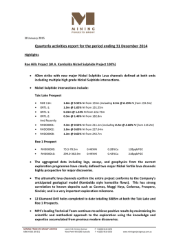
29th January 2015 Diamond Drilling at Roe 1 Prospect Highlights a New Thick and Nickel Sulphide Fertile Lava channel Assay results confirm elevated Ni-Cu-PGE geochemistry has been intersected in Diamond drill holes RHDD0009 & RHDD0010 (Figure 1) at the Roe 1 Prospect located ~35km north of Talc Lake. The assays confirm the existence of a new prospective major lava channel at the Roe 1 Prospect. This also significantly increases the prospectivity of the entire 40km strike containing a new major discovery. The identification of multiple fertile lava channels at both ends of the strike increases the scope of the system while still conforming to the Company’s geological “Cabbage Leaf” model (Kambalda style komatiite flows). The assays show the ultramafic rock in the lava channel are comprised of a lizardite serpentinite that is very similar to the Cosmos ultramafic geology which is a very encouraging sign that the system is highly prospective. MPJ has now successfully completed the first stratigraphic drill cross section at the Roe 1 prospect, as part of the planned definition stage of exploration. Two diamond holes have been completed to date and the third hole was partially completed prior to the Christmas break totalling 1005.5m. Down Hole Electro Magnetic (DHEM) surveys are still yet to be conducted on RHDD0009 & RDH0010 to assess the extent of the mineralisation. The technical team is very excited with the results and has expanded the next stage of the programme to test strategic targets along the entire 40km strike. This will include an extensive geophysical ground survey. MPJ’s leading technical team continues to achieve positive results by maintaining its scientific and methodical approach to the exploration using the knowledge and expertise accumulated from previous modern discoveries. Mining Projects Group Limited (ASX:MPJ) (“the Company”) is pleased to announce the intersection of further fertile Nickel (Ni) geochemistry in the Company’s recently completed diamond drilling programme at the Roe 1 Prospect (“Roe 1”) within its 100% owned Roe Hills Project. MINING PROJECTS GROUP LIMITED ABN 84 006 189 331 Level 2 43 Ventnor Avenue West Perth WA 6005 Australia P +61(0)8 6144 4492 F +61(0)3 9614 0550 www.miningprojectsgroup.com.au Roe 1 Prospect The first cross section of the diamond drilling has now been completed at Roe 1, the northern most prospect area at the company’s Roe Hills Project (Figure 1). Elevated Ni-Cu-PGE mineralisation (Table 1) was intersected within the core and at the base of a thick (>170m) lizardite serpentinised ultramafic flow which has many similarities and correlations to the Cosmos ultramafic system. Two holes have been completed to date (RHDD0009 & RHDD0010) as shown in Figure 1 and Table 2. This confirms the existence of a thick fertile ‘lizardite’ ultramafic lava channel, with Nickel mineralisation situated in the core and at the base of the system, constituting a growing set of multiple ultramafic pulses. The geology is comparable to that at the Cosmos Nickel Project where the core of the thick lizardite serpentinite system contained large low-grade disseminated sulphide above the rich massive sulphide deposits which were the result of the early ultramafic pulses depositing high grade Nickel sulphide mineralisation at the base and on the flanks of the ultramafic system (Figure 2). This is very encouraging as the rocks at Roe 1 appear to be the fertile upstream portion of an extensive fertile system and the potential for downstream Nickel sulphide deposition is demonstrated in the schematic diagram of the Kambalda “Cabbage Leaf” Model shown in Figure 3. The confirmation of multiple fertile lava channels at both ends of the 40km strike at Roe Hills increases the scope of the entire system while still conforming to the Company’s geological “Cabbage Leaf” model (Kambalda style komatiite flows) (Figure 3). Table 1: Maximum assays results from drill core analysis Hole ID Interval m Max Ni% Max Cu% Max PGE ppb (Pt+Pd) RHDD0009 75.5-78.5m 0.46% 0.28% 128ppb RHDD0010 299.0-302.9m 0.49% 0.42% 218ppb Figure 1: Roe 1 Prospect long-section (looking north-east). Historic drill hole (blue collars) define a Ni-Cu corridor which indicates a “fertile” lava channel. Four drill holes have been planned (red) to test the geochemical anomaly. Holes RHDD0009 & RHDD0010 have been completed to date. RHDD0011 is in progress and will be completed at the commencement of the next stage of drilling. Figure 2: Cross-section of the Cosmos Deep Deposits showing the disseminated Anomaly 1 Deposit in the core of the flow and the higher grade Alec Mairs (AM) Deposits at the base and flanking the thick ultramafic flow (image courtesy of Jubilee Mines). Figure 3: Schematic diagram of the Kambalda “Cabbage Leaf” Model showing the geological position of the mineralisation drilled to date at Talc Lake and the downstream target zone where the formation of massive Nickel Sulphide typically occurs. Four diamond drill holes across 2 cross-sections had been planned at Roe 1 totalling ~1500m, with 1005.5m completed so far (Table 2). Drill hole RHDD0011 on the second cross-section was temporarily suspended at a depth of 290m above the anticipated mineralised zone due to equipment failure prior to Christmas. This will be completed at the commencement of the next stage of drilling along with the last planned hole RHDD0012 (Figure 1). The holes were designed to establish geological stratigraphic control so as to bring Roe 1 in line with Talc Lake’s exploration progress. Managing Director Mr Joshua Wellisch commented: “MPJ’s leading Technical Team continues to achieve positive results by maintaining its scientific and methodical approach to the exploration using the knowledge and expertise accumulated from previous modern Nickel discoveries made by the team. The confirmation of a new major lava channel at Roe 1 is a very exciting progression which significantly increases the prospectivity of the entire 40km strike at Roe Hills. It’s a major credit to Mr Hutchison and our technical team as they continue to pinpoint successful drill holes, rapidly defining strategic target channels highly prospective for major discoveries. The Nickel intersections and the geology recorded in the holes to date at Roe 1 have a very strong correlation to the discovery history of known deposits such as Cosmos, Prospero, Sinclair, Cerberus, Silver Swan and Camelwood Nickel deposits. These deposits were all discovered over a period of time by following the disseminated and narrow Nickel sulphide leads within the core of the lava channel. Once the channel core is located DHEM and clever geological interpretation will assist in the discovery of the bigger, potentially economic Nickel sulphide deposits.” Talc Lake Prospect Talc Lake has Nickel mineralisation intersections over a continuous distance of 400m (Figure 4) and recent intersections further confirm that the system is consistent with the Company’s geological “Cabbage Leaf” model (Kambalda style komatiite flows) as shown by (Figure 3). The down plunge extension significantly expands the projects prospectivity of a major discovery as these disseminated styles of mineralisation typically lead to massive Nickel sulphide accumulations downstream (Figure 4). The key intersections from the Talc Lake Prospect (as previously reported) have clearly defined the Nickel hosting channel which MPJ is targeting (Figure 4 & 5); ROE 114: ORTL-1: ORTL-1: ORTL-2: And Recently RHDD0001: RHDD0002: 1.0m @ 3.53% Ni from 155m ( including 0.5m @ 6.15% Ni from 155.5m ) 1.9m @ 1.65% Ni from 131.55m 0.15m @ 1.33% Ni from 222.75m 0.3m @ 1.46% Ni from 182.8m 4.3m @ 0.53% Ni from 211.1m (including 0.2m @ 2.66% Ni from 215.2m) 1.0m @ 0.69% Ni from 227.64m Most importantly a potentially large scale target has been recognised in an historic Fixed Loop Electromagnetic (FLEM) survey completed over the Talc Lake area which produced the start of an anomaly on the south-eastern edge of the survey (Figure 5). The Late Time response FLEM anomaly had not been previously considered due to its proximity to a larger anomaly which was historically drilled and turned out to be a sulphidic shale hosted conductor. This newly recognised anomaly now aligns with the interpreted komatiite channel direction on the southern side of the known massive sulphur source (Figure 5). This same sulphidic unit was intersected to the east of the Nickel mineralisation in RHDD0001 where the lava channel has thermally eroded into the sulphidic shale providing the sulphur source necessary for the formation of the Nickel sulphide mineralisation. This sulphidic shale is a unique-highly conductive marker horizon and this newly defined FLEM target may be the downstream location of the massive Nickel sulphide accumulation as depicted by the “Cabbage Leaf” model in (Figure 3). Technical Director Neil Hutchison will work closely with the Newexco Team to design and instigate a new High-Powered Electromagnetic (EM) survey over the lava channel area, extending the survey south-easterly to fully define the source of this EM anomaly located on the edge of the historic FLEM survey (Figure 5). Figure 4: Talc Lake long-section showing Nickel Sulphide intersections and geological interpretation. 8 diamond drill holes were successfully completed at Talc Lake totalling 2,888m (Table 2). Down Hole Electro Magnetic (“DHEM”) surveys are still to be conducted on RHDD0007 and RHDD0008 to further confirm strategic targets and will coincide with the surface High-Powered EM survey in 2015. The technical team is very excited with the results and has expanded the next stage of the programme to test strategic targets and ensure capital efficiency. Table 2: Drill Hole Collar Co-ordinates. Collar Coordinates: MGA94 GRID RHDD0001 RHDD0002 RHDD0003 RHDD0004 RHDD0005 RHDD0006 RHDD0007 RHDD0008 RHDD0009 RHDD0010 RHDD0011* EAST NORTH RL 461758 461677 461599 461184 461108 461030 462020 461860 6537487 6537501 6537518 6537803 6537800 6537804 6537300 6537300 451200 451040 451040 6557600 6557600 6557400 300 300 300 305 305 305 300 300 305 305 305 * Note: Hole to be extended and completed. DIP -61 -60 -60 -60 -60 -60 -60 -60 -60 -60 -60 AZIMUTH 092 090 090 090 090 090 090 090 090 090 090 TOTAL EOH DEPTH 283.40m 354.40m 459.20m 256.40m 337.30m 414.00m 392.60m 390.60m 270.00m 437.50m 290.00m* 3885.40m Figure 5: Drill hole location plan over historic FLEM survey data. Recent drilling (red collars) and historic drilling (orange & blue collars) have defined the channel position and location of the sulphidic shale marker unit. Importantly a new target has been defined by a Late Time Channel EM response on the edge of the FLEM survey area within the interpreted position of the lava channel. This anomaly is located ~1,600m south of RHDD0007 & RHDD0008 and is consistent with the Kambalda Style “Cabbage Leaf” Model. The company looks forward to providing further details on the next stage of exploration following a complete review of all results received to date. It is anticipated work will recommence in February 2015. ENDS For further information please contact: Mr Joshua Wellisch Managing Director Mining Projects Group Limited For online Information visit: www.miningprojectsgroup.com.au C O M P E T E N T P E R SO N S T A T E M E N T : Competent Person: The information in this report that relates to Exploration Results or Mineral Resources is based on information compiled and reviewed by Mr N Hutchison, who is a Non-Exec Director for Mining Projects Group and who is a Member of The Australian Institute of Geoscientists. Mr Hutchison has sufficient experience which is relevant to the style of mineralisation and type of deposits under consideration and to the activity which he is undertaking to qualify as a Competent Person as defined in the 2012 Edition of the ‘Australasian Code for Reporting of Exploration Results, Mineral Resources and Ore Reserves.’ (the JORC Code 2012). Mr Hutchison has consented to the inclusion in the report of the matters based on his information in the form and context in which it appears. The Australian Securities Exchange has not reviewed and does not accept responsibility for the accuracy or adequacy of this release. Appendix 1 – Mining Projects Group – Roe Hills Project JORC Code, 2012 Edition – Table 1 Section 1 Sampling Techniques and Data (Criteria in this section apply to all succeeding sections.) Criteria JORC Code explanation Commentary Nature and quality of sampling (eg cut channels, random chips, or specific specialised industry standard measurement tools appropriate to the minerals under investigation, such as down hole gamma sondes, or handheld XRF instruments, etc). These examples should not be taken as limiting the broad meaning of sampling. Include reference to measures taken to ensure sample representivity and the appropriate calibration of any measurement tools or systems used. Aspects of the determination of mineralisation that are Material to the Public Report. In cases where ‘industry standard’ work has been done this would be relatively simple (eg ‘reverse circulation drilling was used to obtain 1 m samples from which 3 kg was pulverised to produce a 30 g charge for fire assay’). In other cases more explanation may be required, such as where there is coarse gold that has inherent sampling problems. Unusual commodities or mineralisation types (eg submarine nodules) may warrant disclosure of detailed information. Drilling techniques Drill type (eg core, reverse circulation, open-hole hammer, rotary air blast, auger, Bangka, sonic, etc) and details (eg core diameter, triple or standard tube, depth of diamond tails, face-sampling bit or other type, whether core is oriented and if so, by what method, etc). Core drilling carried out by OnQ Exploration Solutions using a track-mounted Desco 6500 diamond drill rig. Tri-cone rock roller bit was used to drill from surface till competent rock was encountered. The hole was then completed with NQ2 six metre barrel. Core is oriented using Reflex ACT II RD digital core orientation tool. Drill sample recovery Method of recording and assessing core and chip sample recoveries and results assessed. Measures taken to maximise sample recovery and ensure representative nature of the samples. Whether a relationship exists between Diamond core is logged and recorded in the database. Overall recoveries are >95% and there was no core loss or significant sample recovery problems. Diamond core was reconstructed into continuous Sampling techniques MINING PROJECTS GROUP LIMITED ABN 84 006 189 331 Level 2 43 Ventnor Avenue West Perth WA 6005 Australia P +61(0)8 6144 4492 F +61(0)3 9614 0550 PXRF Analysis on NQ2 core using a handheld Olympus Innovx Delta Premium (DP4000C model) Portable XRF analyser. Measurements were taken on surface of the core and depth intervals recorded. NQ sized cores were sawn with manual brick saw and half split prior to sampling and submitted to the lab. Half core samples submitted for highest quality and best representation of the sampled material and sample intervals are checked by the supervising geologist and field technician throughout the sampling process. All sampling is based on diamond drill core. Sample selection is based on geological core logging and sampled to geological contacts. Individual assay samples typically vary in length from a minimum of 0.2m and a maximum length of 1.2m. www.miningprojectsgroup.com.au Criteria JORC Code explanation Commentary sample recovery and grade and whether sample bias may have occurred due to preferential loss/gain of fine/coarse material. Logging Subsampling techniques and sample preparation Quality of assay data and laboratory tests runs on an angle iron cradle for orientation marking. Depths are checked against depth given on core blocks. Whether core and chip samples have been geologically and geotechnically logged to a level of detail to support appropriate Mineral Resource estimation, mining studies and metallurgical studies. Whether logging is qualitative or quantitative in nature. Core (or costean, channel, etc) photography. The total length and percentage of the relevant intersections logged. If core, whether cut or sawn and whether quarter, half or all core taken. If non-core, whether riffled, tube sampled, rotary split, etc and whether sampled wet or dry. For all sample types, the nature, quality and appropriateness of the sample preparation technique. Quality control procedures adopted for all sub-sampling stages to maximise representivity of samples. Measures taken to ensure that the sampling is representative of the in situ material collected, including for instance results for field duplicate/second-half sampling. Whether sample sizes are appropriate to the grain size of the material being sampled. The nature, quality and appropriateness of the assaying and laboratory procedures used and whether the technique is considered partial or total. For geophysical tools, spectrometers, handheld XRF instruments, etc, the parameters used in determining the analysis including instrument make and model, reading times, calibrations factors applied and their derivation, etc. Nature of quality control procedures adopted (eg standards, blanks, duplicates, external laboratory checks) and whether acceptable levels of accuracy (ie lack of bias) and precision have been established. Geologic logging is carried out on the core and recorded as qualitative description of colour, lithological type, grain size, structures, minerals, alteration and other features. All cores are photographed using a digital camera. Geotechnical logging comprises recovery and RQD measurements. Cores were sawn and half split prior to sampling and submitted to the lab. Half core samples submitted for highest quality and best representation of the sampled material. Duplicates not required. Cut sheets prepared and checked by geologist and field technician to ensure correct sample representation. All samples were collected from the same side of the core. Samples were submitted to SGS Laboratories in Kalgoorlie for sample preparation before pulps are freighted overnight to SGS Newburn Labs in Perth for multielement analysis by sodium peroxide fusion followed by ICPOES finish. PGEs are assayed using Fire Assay method. Field reading are estimated using Olympus Innovx Delta Premium (DP4000C model) handheld XRF analyser prior to laboratory analysis. Reading times employed was 15 sec/beam for a total of 30 sec using 2 beam Geochem Mode. Handheld XRF QAQC includes supplied standards and blanks Criteria JORC Code explanation Verification of sampling and assaying The verification of significant intersections by either independent or alternative company personnel. The use of twinned holes. Documentation of primary data, data entry procedures, data verification, data storage (physical and electronic) protocols. Discuss any adjustment to assay data. Primary data was collected using Excel templates utilizing lookup codes on laptop computers. Harjinder Kehal, (member of AusIMM) and consultant to the company has visually verified the significant intersections in the diamond core. Location of data points Accuracy and quality of surveys used to locate drill holes (collar and down-hole surveys), trenches, mine workings and other locations used in Mineral Resource estimation. Specification of the grid system used. Quality and adequacy of topographic control. Drill collars are surveyed by modern hand held GPS units with accuracy of 5m which is sufficient accuracy for the purpose of compiling and interpreting results. Data spacing and distribution Data spacing for reporting of Exploration Results. Whether the data spacing and distribution is sufficient to establish the degree of geological and grade continuity appropriate for the Mineral Resource and Ore Reserve estimation procedure(s) and classifications applied. Whether sample compositing has been applied. Minimal sample spacing for assay samples is 15cm and maximum sample spacing is 1.1m. Sample spacing width is dependent on geological or grade distribution boundaries. No sample compositing will be applied. Orientation of Whether the orientation of sampling achieves unbiased sampling of possible data in structures and the extent to which this is relation to known, considering the deposit type. geological If the relationship between the drilling structure orientation and the orientation of key Commentary Diamond drill holes oriented to the east and stratigraphically define the centre of the komatiite lava channel and locate the source of the Nickel sulphide mineralisation. Holes are designed to intersect the geological contacts as close to perpendicular as possible. Core samples are being cut in the field at the project site by MPJ personnel. They will be delivered to the laboratory be the field personnel. mineralised structures is considered to have introduced a sampling bias, this should be assessed and reported if material. Sample security The measures taken to ensure sample security. Audits or reviews The results of any audits or reviews of sampling techniques and data. N/A Section 2 Reporting of Exploration Results (Criteria listed in the preceding section also apply to this section.) Criteria JORC Code explanation Commentary Type, reference name/number, location and ownership including agreements or material issues with third parties such as joint ventures, partnerships, overriding royalties, native title interests, historical sites, wilderness or national park and environmental settings. The security of the tenure held at the time of reporting along with any known impediments to obtaining a licence to operate in the area. Exploration done by other parties Acknowledgment and appraisal of exploration by other parties. Significant past work has been carried out by other parties for both Ni and Au exploration including, surface geochemical sampling, ground electromagnetic surveys, RAB, AC, RC and DD drilling. This is acknowledged in past ASX announcements. Geology Deposit type, geological setting and style of mineralisation. Target is Kambalda, Cosmos and Black/Silver Swan style Komatiitic Ni hosted in ultramafic rocks within the project. Drill hole Information A summary of all information material to the understanding of the exploration results including a tabulation of the following information for all Material drill holes: o easting and northing of the drill hole collar o elevation or RL (Reduced Level – elevation above sea level in metres) of the drill hole collar o dip and azimuth of the hole o down hole length and interception depth o hole length. If the exclusion of this information is justified on the basis that the information is not Material and this exclusion does not detract from the understanding of the report, the Competent Person should clearly explain why this is the case. Co ordinates and other attributes of diamond drillholes are included in the release. Data aggregation methods In reporting Exploration Results, weighting averaging techniques, maximum and/or minimum grade truncations (eg cutting of high grades) and cut-off grades are usually Material and should be stated. Exploration results will be lengthweight average where applicable, no cut-off grade applied. Mineral tenement and land tenure status Mining Project Group Limited owns 100% of the tenements. The project consists of 5 ELs. The Project is Located on Vacant Crown Land. At the time of writing these licenses expire between March 2015 and May 2016. Criteria JORC Code explanation Commentary Where aggregate intercepts incorporate short lengths of high grade results and longer lengths of low grade results, the procedure used for such aggregation should be stated and some typical examples of such aggregations should be shown in detail. The assumptions used for any reporting of metal equivalent values should be clearly stated. Relationship between mineralisation widths and intercept lengths These relationships are particularly important in the reporting of Exploration Results. If the geometry of the mineralisation with respect to the drill hole angle is known, its nature should be reported. If it is not known and only the down hole lengths are reported, there should be a clear statement to this effect (eg ‘down hole length, true width not known’). All intercepts reported are measured in down hole metres. Diagrams Appropriate maps and sections (with scales) and tabulations of intercepts should be included for any significant discovery being reported These should include, but not be limited to a plan view of drill hole collar locations and appropriate sectional views. Suitable summary plans have been included in the body of the report. Balanced reporting Where comprehensive reporting of all Exploration Results is not practicable, representative reporting of both low and high grades and/or widths should be practiced to avoid misleading reporting of Exploration Results. Other exploration data, if meaningful and material, should be reported including (but not limited to): geological observations; geophysical survey results; geochemical survey results; bulk samples – size and method of treatment; metallurgical test results; bulk density, groundwater, geotechnical and rock characteristics; potential deleterious or contaminating substances. The nature and scale of planned further work (eg tests for lateral extensions or depth extensions or large-scale step-out drilling). Diagrams clearly highlighting the areas of possible extensions, including the main geological interpretations and future drilling areas, provided this information is not commercially sensitive. Minimum, maximum and average PXRF results have been reported. Laboratory assay results will vary from the PXRF results. Multi-element analysis was conducted routinely on all samples for a base metal suite and potentially deleterious elements including Al,As,Co,Cr,Cu,Fe,Mg,Ni,S,Ti,Zn, Zr Down Hole Electro-Magnetics (DHEM) is proposed in conjunction with the already successful geochemical and geological modelling. Further DD drilling is continuing and targeted to locate the modelled centre of the host komatiitic lava channel which is interpreted to be the source of the Nickel sulphide mineralisation Other substantive exploration data Further work Criteria JORC Code explanation Commentary
© Copyright 2026
