
Performance and Noise modelling of the Short Period Seismometer
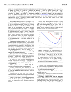
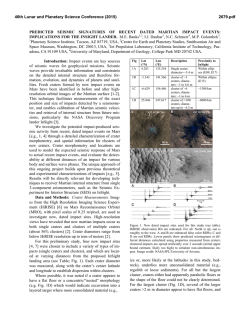
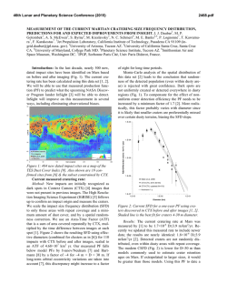
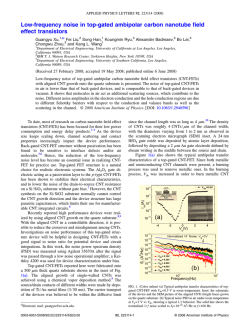
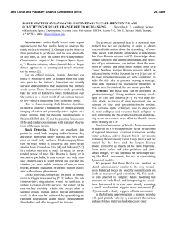
46th Lunar and Planetary Science Conference (2015)
2146.pdf
Performance and Noise modelling of the Short Period Seismometer SEIS-SP, part of the SEIS instrument for
NASA’s 2016 InSight Mission . N. E. Bowles1, W. T. Pike2 , N. Teanby3, G. Roberts6, S. B. Calcutt1, J. Hurley4, P. Coe1, J.
1
Wookey3, P. Dunton 4, I. Standley6, J. Temple1, R. Irshad4, J. Taylor3, T. Warren1 and C. Charalambous2, Atmospheric, Oceanic and Planetary Physics, University of Oxford, Clarendon Laboratory, Oxford, UK ([email protected]),
2
Department of Electrical and Electronic Engineering, Imperial College, London, UK. 3Department of Earth Sciences, University
of Bristol, Bristol, UK, Centre for Nanoscience and Quantum Information, University of Bristol, Bristol, UK, 4RALSpace, Science and Technology Facilities Council Rutherford Appleton Laboratory, UK, 5Kinemetrics Inc. Pasadena CA, USA,
6
Department of Earth and Planetary Sciences, Birkbeck College, University of London, London, UK.
Introduction: NASA’s InSight mission [1] is due
to land on Mars in September 2016 with instrumentation designed to probe the interior structure of the
planet. One of the main instruments included in the
payload is the seismic instrumentation package SEIS
[2]. SEIS is the critical instrument for delineating the
deep interior structure of Mars, including the thickness
and structure of the crust, the possible composition of
the mantle, and will help to constrain the size of its
core.
The complete SEIS package includes the
Very Broad Band (VBB) 3-axis sensor [2] covering the
frequency range 0.005 to 1 Hz and the Short Period
(SEIS-SP) instrument covering the frequency range
0.05 to 40 Hz. To couple the instrument to the Martian
surface, SEIS will be deployed by the lander’s robot
arm and then covered by a wind and thermal shield
(WTS) to isolate it from the weather (Figure 1). SEIS
itself includes aerogel thermal insulation, which combined with the WTS helps to mitigate the effects of
wind and thermal fluctuations.
WTS'
Sensor'
Assembly'
Thermal'
Blanket'
Figure 1. Layout of the SEIS instrument package, showing
the Wind and Thermal Shield (WTS), thermal blanket and
complete SEIS sensor assembly. (Image: InSight SEIS
team).
SEIS-SP sensor description: The SEIS-SP sensor
is an innovative micro-machined silicon device that is
hermetically sealed (Figure 2, [3]).The sensor consists
of a micromachined silicon suspension supporting a
proof mass that moves laterally. The proof-mass position is sensed by a periodic linear capacitive array
transducer allowing highly sensitive position detection
combined with feedback control at multiple null
points. Operation at any of these points enables the
sensor to function over a large tilt range without compromising the noise performance. As well as the capacitive sensing elements, the proof mass has planar coils
on the surface to electromagnetic actuator when placed
in a static magnetic field.
Each of the three sensor axes is packaged as a separate unit, and includes thick-film hybrid pre-amplifier
electronics designed to operate over the full range of
expected martian surface temperature conditions (e.g.
150 - 290 K). The anticipated noise floor of the flight
device is 0.5 ng/√Hz in the 0.1 to 10Hz band.
Figure 2. An integrated SEIS-SP sensor die, 25 x 25 mm.
InSight poses some unique problems in data extraction not encountered in terrestrial seismology. Part of
the challenge concerns the unknown nature of the
planet’s seismic signal itself, including potential
sources and transmission. But independent of the seismic analysis, perhaps the biggest challenge is isolating
the seismic portion of the signal in the dataset returned
to Earth. Terrestrial seismology sidesteps this problem
by deploying instruments in vaults that considerably
attenuate any aseismic contributions to the seismometer output.
Figure 3a illustrates the signal paths for a terrestrial
vault installation with a seismometer signal, x0 with
temperature and pressure, x1 and x2, filtered through
the vault and instrument transfer function, D0,1,2 and
I0,1,2, which in general contain proportional, integral
and differential terms. Ideally three entirely independent signal paths prevent crosstalk between the signals.
In practice a deep vault will minimise any interaction
between the three signals, even if the seismometer itself has finite temperature and pressure coefficients.
For all the signal paths there is an inevitable contribution to each signal path from the instrument noise,
n0,1,2. On Earth the seismometer has been designed
such that this noise is below the weakest seismic signal
expected. When taken altogether, the separation of the
signal pathways enables the seismologist to concentrate immediately on the seismic analysis of the seismometer
output.
46th Lunar and Planetary Science Conference (2015)
Figure 3. Flow for SEIS-SP noise source modeling and
characterization – see text for details.
On Mars it is much more difficult to minimise the
signal interactions (Figure 3b). InSight will be deploying SEIS on the surface, not in a vault, though there is
some mitigation from the wind and thermal shield
placed over SEIS. Nevertheless the cross terms in the
deployment signal transfer function, Dij, cannot not be
neglected as on Earth and the instrument cross terms in
Iij, will mix the temperature and pressure signals with
the seismic signal. Furthermore, the instrument noise
contributions, n0,1,2, can no longer be guaranteed to be
below the seismic signal. The resulting seismic channel output, z0, will therefore have substantial contributions from aseismic signals and the instrument noise
that will need to be removed as far as possible before
any seismic analysis. This work can therefore be regarded as trying to best estimate Dij and Iij through an
understanding of the physical interactions that underlie
these transfer functions.
SEIS-SP Regolith Noise Transfer function
Measurements: The transfer function between the
WTS and the SEIS-SP sensor package was quantified
in analogue environments, both in the laboratory in a
2m by 2m sandpit, and in basaltic desert environments
at the Hverfjall Cinder cone apron, Iceland [4]. These
experiments found that around 2% of the WTS generated seismic noise is transferred to the SEIS instruments at 5Hz. This is five times less than predicted by
simple elastic theory and suggests anelastic regolith
properties. These anelastic effects, which will affect
vibrations transmitted from the spacecraft and other
natural sources as well at the WTS, are being further
quantified by the Bristol group and will be incorporated into the overall noise model.
Determination of noise for the SP instrument:
The components of the SP self-noise have been modelled in PSPICE as part of the instrument analysis and
confirmed by coherency testing alongside high performance
terrestrial
seismometers
in
lowenvironmental-noise vaults (e.g. [5])
Determination of the environmental con-
2146.pdf
tributions: Data from the Auxiliary Payload Sensor
Subsystem (APSS) on the InSight lander provides
measurements of the atmospheric pressure, temperature and wind speed as part of the mission’s continuous
housekeeping. The primary role of the APSS is to
determine when the environmental noise exceeds the
SEIS noise requirement i.e. to flag potentially ‘bad’
data. The VBB team also intends to decouple the environmental background from the seismic signal also
using the APSS data and a similar approach, which is
described here.
1) For wind/pressure turbulence effects: We are developing empirical models and numerical simulations
using testing in environmental chambers and applying
finite-element model analyses across the frequency
band of the SP sensors for a representative range of
a) Background wind/pressure flows; b) Wind velocity
fluctuations (using the Viking data as a baseline for a
static lander) for both night and day conditions; and c)
Pressure fluctuations (initially using data from Mars
Pathfinder).
2) For temperature effects: In a similar way to the
wind/pressure turbulence effects, we are developing
models to map variations in the atmospheric and surface temperatures to measurements made by the SP.
a) Initial numerical analysis will once again use Viking
and Pathfinder data as example static landers with upto-date physical models of the SEIS instrument system.
b) Laboratory measurements will use our existing lownoise cryo-test rig (built as part of the SP electronics
qualification process) and flight-like SP hardware including sensors, feedback board electronics.
Future work: The SEIS-SP flight sensor units are
now in final production. Working closely with other
members of the SEIS science and engineering teams,
we will work to combine measurements of the instrument’s transfer function, regolith properties and environmental noise sources to generate a comprehensive
instrument model. It is hoped that this model will help
with the detailed analysis of the SEIS-SP instrument
when it is installed on the surface of Mars in September 2016.
Acknowledgements: The SEIS-SP team would
like thank the UK Space Agency for funding the development and testing of the SEIS-SP sensor. The
assistance and support of the InSight mission team
around the world and the SEIS instrument team in particular is gratefully acknowledged.
References: [1] Banerdt, W. B. et al. (2013)
LPSC XXXXIII Abstract #1915. [2] Mimoun D. H. et
al. (2012), LPSC XXXXIII, abstract #1493. [3] Pike,
W.T. et al.(2014) Proc. IEEE SENSORS, 1599 – 1602.
[4] Teanby, N. A. et al. (2013) , LPSC XXXXIV, abstract #1035. [5] http://www.bristol.ac.uk/nsqi-centre/


© Copyright 2026