
35 - EvoScan
35A-1
SERVICE BRAKES
CONTENTS
BASIC BRAKE SYSTEM . . . . . . . . . . . . . . . . . . . . . . . . . . . . . . . . . . . . . . . . . 35A
ANTI-SKID BRAKING SYSTEM (ABS) <4WD> . . . . . . . . . . . . . . . . . . . . . . 35B
35A-2
BASIC BRAKE
SYSTEM
CONTENTS
GENERAL INFORMATION . . . . . . . . . . . . . . . . . . 3
SERVICE SPECIFICATIONS . . . . . . . . . . . . . . . . . 5
LUBRICANTS . . . . . . . . . . . . . . . . . . . . . . . . . . . . . . 6
SEALANT . . . . . . . . . . . . . . . . . . . . . . . . . . . . . . . . . . 6
SPECIAL TOOLS . . . . . . . . . . . . . . . . . . . . . . . . . . . 6
ON-VEHICLE SERVICE . . . . . . . . . . . . . . . . . . . . . 7
Bleeding . . . . . . . . . . . . . . . . . . . . . . . . . . . . . . . . . . . . 10
Brake Fluid Level Sensor Check . . . . . . . . . . . . . 11
Disc Brake Pad Check and Replacement . . . . . . 11
Disc Brake Rotor Check . . . . . . . . . . . . . . . . . . . . . 13
Brake Disc Thickness Check . . . . . . . . . . . . . . . . . 14
Brake Disc Run-out Check and Correction . . . . 14
BRAKE PEDAL . . . . . . . . . . . . . . . . . . . . . . . . . . . 16
Brake Pedal Check and Adjustment . . . . . . . . . . . . 7
PROPORTIONING VALVE, MASTER
CYLINDER AND BRAKE BOOSTER . . . . . . . . 17
Brake Booster Operating Test . . . . . . . . . . . . . . . . . 8
Master Cylinder . . . . . . . . . . . . . . . . . . . . . . . . . . . . . 19
Check Valve Operation Check . . . . . . . . . . . . . . . . . 9
Proportioning Valve Function Test
<Vehicles without ABS> . . . . . . . . . . . . . . . . . . . . . . 9
DISC BRAKE . . . . . . . . . . . . . . . . . . . . . . . . . . . . . 20
BASIC BRAKE SYSTEM - General Information
35A-3
GENERAL INFORMATION
The brake system offers high dependability and durability along with improved braking performance and
brake sensitivity.
SERVICE PRECAUTION <VEHICLES WITH BREMBO BRAKING SYSTEM>
Take care not to contact the parts or tools to the caliper because the paint of caliper will be scratched.
SPECIFICATIONS
Items
Specifications
Type
Tandem type
I.D. mm
26.9
Type
Vacuum type, tandem
Effective dia. of power cylinder mm
205 + 230
Boosting ratio
4.5 (Pedal depressing force: 230 N)
Rear wheel hydraulic
control method
Vehicles with ABS <RS, RS-Ⅱ>
Electronic brake-force distribution (EBD)
Vehicles without ABS <RS>
Proportioning valves
Proportioning valves
<Vehicles
Vehicles without ABS>
ABS
Type
Single type ¢ 2
Decompression ratio
0.25
Front brakes
<RS
RS (standard)>
(standard)
Type
Floating caliper, 2 piston, ventilated disc
Disc effective dia. ¢ thickness mm
227 ¢ 24
Wheel cylinder I.D. mm
42.9 (¢2)
Pad thickness mm
10.0
Clearance adjustment
Automatic
Type
4 opposed piston, ventilated disc
<Brembo braking system>
Disc effective dia. ¢ thickness mm
263 ¢ 32
Wheel cylinder I.D. mm
40.0 (¢2), 46.0 (¢2)
Pad thickness mm
10.0
Clearance adjustment
Automatic
Type
Floating caliper, 1 piston, ventilated disc
Disc effective dia. ¢ thickness mm
237 ¢ 20
Wheel cylinder I.D. mm
34.9
Pad thickness mm
10.0
Clearance adjustment
Automatic
Type
2 opposed piston, ventilated disc
<Brembo braking system>
Disc effective dia. ¢ thickness mm
252 ¢ 22
Wheel cylinder I.D. mm
40.0 (¢2)
Pad thickness mm
9.0
Clearance adjustment
Automatic
Master cylinder
Brake booster
Front brakes
<RS (option), RS-II>
Rear brakes
<RS
RS (standard)>
(standard)
Rear brakes
<RS (option), RS-II>
Brake fluid
DOT3 or DOT4
35A-4
BASIC BRAKE SYSTEM - General Information
CONSTRUCTION DIAGRAM
<Vehicles with ABS>
Brake booster*
Hydraulic unit*
Rear disc brake
Parking brake
Master cylinder*
Front disc brake
<Vehicles without ABS>
Brake booster*
Master cylinder and
proportioning valves*
Rear disc brake
Parking brake
Front disc brake
NOTE
For R.H. drive vehicles, only the position indicated by the * is symmetrical.
BASIC BRAKE SYSTEM - Service Specifications
35A-5
SERVICE SPECIFICATIONS
Items
Standard value
Limit
Brake pedal height mm
169.1 - 172.1
-
Brake pedal play mm
3-8
-
Brake pedal to floorboard clearance when the brake pedal is depressed mm
90 or more
-
Brake booster push rod protrusion amount mm
8.98 - 9.23
-
Proportioning valve
<Vehicles without ABS>
Split point MPa
2.70 - 3.19
-
Output fluid pressure MPa <Input fluid pressure: 6.86Mpa>
3.68 - 4.17
-
Output fluid pressure difference between left and right MPa
-
0.49
Pad thickness mm
10.0
2.0
Disc thickness mm
24 0
24.0
22 4
22.4
Disc run-out mm
-
0.03
Drag force N
51 or less
-
Pad thickness mm
10.0
2.0
Disc thickness mm
32 0
32.0
29 8
29.8
Disc run-out mm
-
0.03
Drag force N
69 or less
-
Pad thickness mm
10.0
2.0
Disc thickness mm
20 0
20.0
18 4
18.4
Disc run-out mm
-
0.03
Drag force N
69 or less
-
Pad thickness mm
9.0
2.0
Disc thickness mm
22 0
22.0
20 4
20.4
Disc run-out mm
-
0.03
Drag force N
69 or less
-
Front wheel bearing axial play mm
-
0.06
Rear wheel bearing axial play mm
-
0.05
Front disc brake
<RS (standard)>
Brembo front disc brake
<RS (option),
(option) RS-II>
RS II>
Rear disc brake
<RS (standard)>
Brembo rear disc brake
<RS (option),
(option) RS-II>
RS II>
35A-6
BASIC BRAKE SYSTEM - Lubricants/Sealant/Special Tools
LUBRICANTS
Items
Specified Lubricant
Quantity
Brake fluid
DOT3 or DOT4
As required
Piston, wheel cylinder body
Piston boot, piston seal, shim
Repair kit grease
Guide pin, lock pin, pin boot <Except for Brembo disc brake>
Pad assembly <Brembo disc brake>
SEALANT
Items
Specified sealant
Remarks
Fitting
3M ATD Part No. 8661, 8663 or equivalent
Semi-drying sealant
SPECIAL TOOLS
Tool
A
Number
Name
Use
MB991568
Push rod adjusting
socket
Adjustment of the brake booster push rod
protrusion amount
MB990964
A: MB990520
Brake tool set
Pushing-in of the disc brake piston
D Disc brake piston pushing-in
MB990998
Front hub remover
and installer
Provisional holding of the wheel bearing
BASIC BRAKE SYSTEM - On-vehicle Service
35A-7
ON-VEHICLE SERVICE
BRAKE PEDAL CHECK AND ADJUSTMENT
BRAKE PEDAL HEIGHT
1. Turn up the carpet, etc. under the brake pedal.
2. Measure the brake pedal height as illustrated.
Standard value (A): 169.1 - 172.1 mm
3. If the brake pedal height is not within the standard value,
follow the procedure below.
(1) Disconnect the stop lamp switch connector.
(2) Loosen the stop lamp switch by turning it approx.
1/4 turns anticlockwise.
(3) Remove the brake booster. (Refer to P.35A-17.)
A
NOTE
With the master cylinder and brake pipe connected,
remove the brake booster only.
(4) Adjust the brake pedal height by turning the clevis.
NOTE
When the clevis is turned 180_, the pedal hight is
changed approximately 2.4 mm.
Clevis
(5) Install the brake booster. (Refer to P.35A-17.)
(6) Measure brake pedal height, and ensure that the
measured value is within the specified value. When
it is out of the specified value, repeat Step (3) - (6).
(7) Insert the stop lamp switch until it’s thread part touches
the stopper. Then lock the stop lamp switch by turning
it approx. 1/4 turns clockwise, and confirm that the
clearance between the switch plunger and the stopper
is as shown.
(8) Connect the connector at the stop lamp switch.
Stopper
0.5 - 1.0 mm
Caution
Check that the stop lamp does not illuminate when
the brake pedal is not depressed.
4. Return the carpet, etc.
BRAKE PEDAL FREE PLAY
1. With the engine stopped, depress the brake pedal two
or three times, After eliminating the vacuum in the power
brake booster, press the pedal down by hand, and confirm
that the amount of movement before resistance is met
(the free play) is within the standard value.
Standard value (B): 3 – 8 mm
B
35A-8
BASIC BRAKE SYSTEM - On-vehicle Service
2. If the brake pedal play is not within the standard value,
check the following, and adjust or replace if necessary:
D Excessive play between the brake pedal and the clevis
pin, or between the clevis pin and the brake booster
operating rod
D Brake pedal height
D Installation position of the stop lamp switch, etc.
CLEARANCE BETWEEN BRAKE PEDAL AND FLOOR
BOARD
1. Turn up the carpet etc. under the brake pedal.
2. Start the engine, depress the brake pedal with
approximately 500 N of force, and measure the clearance
between the brake pedal and the floorboard.
Standard value (C): 90 mm or more
3. If the clearance is outside the standard value, check for
air trapped in the brake line and thickness of the disc
brake pad and dragging in the parking brake.
Adjust and replace defective parts as required.
C
4. Return the carpet, etc.
Good
No good
When engine is
stopped
When engine is
started
Good
No good
BRAKE BOOSTER OPERATING TEST
For simple checking of the brake booster operation, carry
out the following tests:
1. Run the engine for one or two minutes, and then stop
it.
If the pedal depresses fully the first time but gradually
becomes higher when depressed succeeding times, the
booster is operating properly. If the pedal height remains
unchanged, the booster is defective.
2. With the engine stopped, step on the brake pedal several
times.
Then start the engine while the brake pedal is stepped
on.
If the pedal moves downward slightly, the booster is in
good condition. If there is no change, the booster is
defective.
3. With the engine running, step on the brake pedal and
then stop the engine.
Hold the pedal depressed for 30 seconds. If the pedal
height does not change, the booster is in good condition.
If the pedal rises, the booster is defective.
If the above three tests are okay, the booster performance
can be determined as good.
If one of the above three tests is not okay at least, the check
valve, vacuum hose, or booster will be defective.
BASIC BRAKE SYSTEM - On-vehicle Service
35A-9
CHECK VALVE OPERATION CHECK
1. Remove the vacuum hose. (Refer to P.35A-17.)
Caution
The check valve should not be disassembled from
the vacuum hose as they are united as one part.
2. Check the operation of the check valve by using a vacuum
pump.
Valve
Spring
Booster A
side
B
Intake
manifold
side
Accept/reject criteria
Connection at the brake
booster side (A)
A negative pressure (vacuum) is
created and held.
Connection at the intake
manifold side (B)
A negative pressure (vacuum) is
not created.
Caution
If the check valve is defective, always replace it as
an assembly unit together with the vacuum hose.
PROPORTIONING VALVE FUNCTION TEST
<Vehicles without ABS>
Pressure gauge (A)
Output port
Output port
Pressure gauge (B)
Proportioning valve
Output
pressure
<Pressure
gauge (B)>
Vacuum pump
connection
Split point
Caution
The proportioning valves are installed independently for
the right and left brake lines. Always measure each valve.
1. Connect two pressure gauges to the output port of the
master cylinder and output port of the proportioning valve.
2. Bleed the brake line and the pressure gauges. (Refer
to P.35A-10.)
3. Depress the brake pedal gradually. Then check that the
split point, where the output fluid pressure begins to drop
in proportion to the output fluid pressure, is at the standard
value.
Standard value: 2.70 - 3.19 MPa
Input pressure
<Pressure gauge (A)>
4. Depress the brake pedal more strongly than at the above
step. Then check that the output fluid pressure is at the
standard value when the input fluid pressure is 6.86 MPa.
Standard value: 3.68 - 4.17 MPa
5. Measure each output fluid pressure at both valves, and
check that the difference between the two is at the limit
value or less.
Limit: 0.49 MPa
6. If the measured pressure exceeds the limit, replace the
proportioning valve.
35A-10
BASIC BRAKE SYSTEM - On-vehicle Service
BLEEDING
Caution
Specified brake fluid: DOT3 or DOT4
Always use the specified brake fluid. Avoid using a
mixture of the specified brake fluid and other fluid.
MASTER CYLINDER BLEEDING
The master cylinder used has no check valve, so if bleeding
is carried out by the following procedure, bleeding of air from
the brake pipeline will become easier. (When brake fluid is
not contained in the master cylinder.)
1. Fill the reserve tank with brake fluid.
2. Keep the brake pedal depressed.
3. Have another person cover the master cylinder outlet
with a finger.
4. With the outlet still closed, release the brake pedal.
5. Repeat steps 2 - 4 three or four times to fill the inside
of the master cylinder with brake fluid.
Air bleeder screw
BREMBO DISC BRAKE BLEEDING
Caution
Take care not to contact the parts or tools to the caliper
because the paint of caliper will be scratched. And if
there is brake fluid on the caliper, wipe out quickly.
Connect a vinyl tube to the outer end of the air bleeder screw
to bleed the circuit of air. Then, connect the vinyl tube to
the inner end and bleed the circuit of air. Except for these,
the conventional procedures shall be followed. After the circuit
has been bled of air, tighten both air bleeder screws securely.
Vehicles with ABS
4 (2)
1 (3)
2 (4)
3 (1)
( ): R.H. drive vehicles
Vehicles without ABS
4, 6 (1, 3)
2 (5)
1, 3 (4, 6)
5 (2)
( ): R.H. drive vehicles
BRAKE PIPE LINE BLEEDING
Bleed the air in the sequence shown in the figure.
BASIC BRAKE SYSTEM - On-vehicle Service
35A-11
BRAKE FLUID LEVEL SENSOR CHECK
The brake fluid level sensor is in good condition if there is
no continuity when the float surface is above “MIN” and if
there is continuity when the float surface is below “MIN”.
DISC BRAKE PAD CHECK AND REPLACEMENT
<Except for Brembo disc brake>
NOTE
The wear indicator contacts the brake disc when the brake
pad thickness reaches approximately 2 mm and emit a
squealing sound to warn the driver.
Front
1. Check the brake pad thickness through the caliper body
check port.
Rear
Standard value: 10.0 mm
Limit: 2.0 mm
2. When the thickness is less than the limit, always replace
the pads at an axle set.
14Z0017
Front
3. Remove the pin bolt. Pivot the caliper assembly and hold
it with wires.
Rear
Caution
Do not wipe off the special grease that is on the pin
or allow it to contaminate the pin.
Front
Rear
3
2
3
1
2
4
1
3
4
3
4. Remove the following parts from the caliper support.
1. Pad and wear indicator assembly
2. Pad assembly
3. Clip
4. Outer shim
5. In order to measure the brake drag force after pad
installation, measure the rotary-sliding resistance of the
hub with the pads removed. (Refer to P.35A-21.)
6. Install the pads and caliper assembly, and then check
the brake drag force. (Refer to P.35A-21.)
35A-12
BASIC BRAKE SYSTEM - On-vehicle Service
<Brembo disc brake>
Caution
Take care not to contact the parts or tools to the caliper
because the paint of caliper will be scratched. And if
there is brake fluid on the caliper, wipe out quickly.
NOTE
The wear indicator contacts the brake disc when the brake
pad thickness reaches approximately 2 mm and emit a
squealing sound to warn the driver.
Front
Rear
Pads
1. Check the brake pad thickness through the caliper body
check port.
Standard value: 10.0 mm <Front>, 9.0 mm <Rear>
Limit: 2.0 mm
Pads
2. When the thickness is less than the limit, always replace
the pads at an axle set.
(1) Holding the cross spring with one hand, pull the pin
out of the caliper.
(2) Remove the pad from the caliper.
(3) To measure brake drag force after new pads have
been installed, use a spring balance to measure the
turning sliding resistance of the hub with the pads
removed. (Refer to P.35A-21.)
MB990520
(4) Clean the piston and, using the special tool, push
the piston into the cylinder.
BASIC BRAKE SYSTEM - On-vehicle Service
Front
35A-13
(5) Apply repair kit grease to the portions of the pads
indicated on the left. At this time, make sure that
the grease will not be applied to any other surfaces.
(6) Mount the pads to the caliper so that its side with
the wear indicator is on the outside of the vehicle.
With the rear pads, ensure that the arrow on the
pad faces in the same direction as the brake disc
turns when the vehicle moves forward.
Rear
(7) Holding the cross spring with one hand, fit pins in
the caliper.
(8) Using a spring balance, measure the turning sliding
resistance of the hub in the forward direction.
(9) Find the brake disc drag force [the difference in
measurements taken in step(3) and in step(8)].
Pins
Cross
spring
Standard value: 69 N or less
DISC BRAKE ROTOR CHECK
Caution
When servicing disc brakes, it is necessary to exercise caution to keep the disc brakes within
the allowable service values in order to maintain normal brake operation.
Before re-finishing or re-processing the brake disc surface, the following conditions should be checked.
Inspection items
Remarks
Scratches, rust, saturated lining materials
and wear
D
D
If the vehicle is not driven for a certain period, the sections of
the discs that are not in contact with lining will become rusty, causing
noise and shuddering.
If grooves resulting from excessive disc wear and scratches are
not removed prior to installing a new pad assembly, there will
momentarily be inappropriate contact between the disc and the
lining (pad).
Run-out or drift
Excessive run-out or drift of the discs will increase the pedal depression
resistance due to piston knock-back.
Change in thickness (parallelism)
If the thickness of the disc changes, this will cause pedal pulsation,
shuddering and surging.
Inset or warping (flatness)
Overheating and improper handling while servicing will cause inset or
warping.
35A-14
BASIC BRAKE SYSTEM - On-vehicle Service
BRAKE DISC THICKNESS CHECK
Caution: Brembo disc brake
Take care not to contact the parts or tools to the caliper
because the paint of caliper will be scratched. And if
there is brake fluid on the caliper, wipe out quickly.
1. Using a micrometer, measure disc thickness at eight
positions, approximately 45° apart and 10 mm in from
the outer edge of the disc.
Brake disc thickness <Except for Brembo disc brake>
Standard value: 24.0 mm <Front>, 20.0 mm <Rear>
Limit: 22.4 mm <Front>, 18.4 mm <Rear>
Brake disc thickness <Brembo disc brake>
Standard value:32.0 mm <Front>, 22.0 mm <Rear>
Limit: 29.8 mm <Front>, 20.4 mm <Rear>
Thickness variation (at least 8 positions)
The difference between any thickness measurements
should not be more than 0.015 mm.
2. If the disc is beyond the limits for thickness, remove it
and install a new one. If thickness variation exceeds the
specification, replace the brake disc or grind it with
on-the-car type brake lathe (“MAD, DL-8700PF” or
equivalent).
M12 flat washer
M12 flat washer
Caution
(1) After a new brake disc is installed, always grind
the brake disc with on-the-car type brake lathe.If
this step is not carried out, the brake disc run-out
exceeds the specified value, resulting in judder.
(2) When the on-the-car type lathe is used, first install
M12 flat washer on the stud bolt in the brake disc
side according to the figure, and then install the
adapter. If the adapter is installed with M12 flat
washer not seated, the brake disc rotor may be
deformed, resulting in inaccurate grinding.
(3) Grind the brake disc with all wheel nuts diagonally
and equally tightened to the specified torque 100
N·m. When all numbers of wheel nuts are not used,
or the tightening torque is excessive or not equal,
the brake disc rotor or drum may be deformed,
resulting in judder.
BRAKE DISC RUN-OUT CHECK AND
CORRECTION
Caution: Brembo disc brake
Take care not to contact the parts or tools to the caliper
because the paint of caliper will be scratched. And if
there is brake fluid on the caliper, wipe out quickly.
1. Remove the brake assembly, and then hold it with wire.
2. Temporarily install the disc with the hub nut.
BASIC BRAKE SYSTEM - On-vehicle Service
35A-15
3. Place a dial gauge approximately 5 mm from the outer
circumference of the brake disc, and measure the run-out
of the disc.
Limit: 0.03 mm or less
4. If the brake disc run-out exceeds the limit, correct it as
follows:
(1) Chalk phase marks on the wheel stud and the brake
disc, which run-out is excessive.
(2) Remove the brake disc. Then place a dial gauge
as shown, and measure the wheel bearing axial play
by pushing and pulling the wheel hub.
Limit: 0.06 mm <Front>, 0.05 mm <Rear>
(3) If the wheel bearing axial play exceeds the limit,
disassemble the hub and knuckle assembly to check
each part.
(4) If the wheel bearing axial play does not exceed the
limit, dephase the brake disc and secure it. Then
recheck the brake disc run-out.
5. If the run-out cannot be corrected by changing the phase
of the brake disc, replace the brake disc or grind it with
the on-the-car type brake lathe ( “MAD, DL-8700PF” or
equivalent).
Caution
(1) After a new brake disc is installed, always grind
the brake disc with on-the-car type brake lathe.
If this step is not carried out, the brake disc run-out
exceeds the specified value, resulting in judder.
M12 flat washer
M12 flat washer
(2) When the on-the-car type lathe is used, first install
M12 flat washer on the stud bolt in the brake disc
side according to the figure, and then install the
adapter. If the adapter is installed with M12 flat
washer not seated, the brake disc rotor may be
deformed, resulting in inaccurate grinding.
(3) Grind the brake disc with all wheel nuts diagonally
and equally tightened to the specified torque 100
N·m. When all numbers of wheel nuts are not used,
or the tightening torque is excessive or not equal,
the brake disc rotor or drum may be deformed,
resulting in judder.
35A-16
BASIC BRAKE SYSTEM - Brake Pedal
BRAKE PEDAL
REMOVAL AND INSTALLATION
Post-installation Operation
Brake Pedal Adjustment (Refer to P.35A-7.)
8
12 ± 2 N·m
5
2
3
14 ± 3 N·m
6
1
4
7
Removal steps
1. Harness connector
2. Stop lamp switch
3. Adjuster
4. Pedal stopper
5. Snap pin
6. Pin assembly
7. Pedal pad
"AA 8. Brake pedal and pedal support
member
INSTALLATION SERVICE POINT
B
A
B
A
"AA BRAKE PEDAL AND PEDAL SUPPORT MEMBER
INSTALLATION
Tighten the brake booster mounting nuts (A), and then the
brake pedal mounting bolts (B).
NOTE
The pedal support member can not be positioned correctly
if the pedal mounting bolts (B) are tightened first as the their
holes are oblong holes.
BASIC BRAKE SYSTEM -
Brake Pedal/Proportioning Valve,
Master Cylinder and Brake Booster
35A-17
INSPECTION
No continuity
Continuity
STOP LAMP SWITCH CHECK
1. Connect an ohmmeter between the stop lamp switch
connector terminals.
2. There should be no continuity between the terminals when
the plunger is pushed in as shown. There should be
continuity when it is released.
4 mm
PROPORTIONING VALVE, MASTER CYLINDER AND BRAKE
BOOSTER
REMOVAL AND INSTALLATION
Pre-removal Operation
D Air Intake Hose and Air Cleaner Removal
<L.H. drive vehicles>
D Strut Tower Bar Removal (Refer to GROUP 42.)
D Brake Fluid Draining
Post-installation Operation
D Brake Fluid Supplying and Air Bleeding
(Refer to P.35A-10.)
D Brake Pedal Adjustment (Refer to P.35A-7.)
D Air Intake Hose and Air Cleaner Installation
<L.H. drive vehicles>
D Strut Tower Bar Installation (Refer to GROUP 42.)
9 <L.H. drive vehicles>
4
9 <R.H. drive vehicles>
2
3
13
15 ± 2 N·m
14
10
1
5
8
10 ± 2 N·m
11
22 ± 3 N·m
5
Proportioning valves
<Vehicles without ABS>
Fitting
Vacuum hose, fitting
<L.H. drive vehicles>
9
16 ± 1 N·m
15
<R.H. drive vehicles>
30 ± 5 N·m
9
Specified Sealant: 3M ATD
Part No.8661, 8663 or
equivalent
6
5
15 ± 2 N·m
14 ± 3 N·m
15 ± 2 N·m
15
7
12
16 ± 1 N·m
15
35A-18
BASIC BRAKE SYSTEM Master cylinder removal steps
1. Clutch hose connection
2. Brake fluid level sensor connector
3. Reservoir cap assembly
4. Brake fluid level sensor
5. Brake pipe connection
6. Proportioning valve
<Vehicles without ABS>
7. O ring <Vehicles without ABS>
8. Master cylinder
Proportioning valve removal steps
<Vehicles without ABS>
5. Brake pipe connection
6. Proportioning valve
7. O ring
Brake booster removal steps
1. Clutch hose connection
2. Brake fluid level sensor connector
Proportioning Valve, Master Cylinder
and Brake Booster
5. Brake pipe connection
8. Master cylinder
"BA D Push rod protrusion amount check and
adjustment
"AA 9. Vacuum hose
(With built-in check valve)
10. Snap pin
11. Pin assembly
12. Clevis
D Remove A/C liquid pipe B from the
retaining clip. (Refer to GROUP 55A
- Refrigerant Line.)
13. Brake booster
14. Sealer
Fitting removal steps
"AA 9. Vacuum hose
(With built-in check valve)
15. Fitting
INSTALLATION SERVICE POINTS
"AA VACUUM HOSE CONNECTION
Insert the vacuum hose to the brake booster with its paint
mark facing upward, and then secure the hose by using the
hose clip.
"BA PUSH ROD PROTRUSION AMOUNT CHECK AND
ADJUSTMENT
1. Measure dimension (A).
Standard value (A) : 8.98 - 9.23 mm
A
Measuring distance A
Block gauge
NOTE
When a negative pressure of 66.7 kPa is applied to the
brake booster, the push rod should protrude 10.27 – 10.53
mm.
BASIC BRAKE SYSTEM -
Proportioning Valve, Master Cylinder
and Brake Booster
35A-19
2. If the protrusion amount is not within the standard value
range, adjust the push rod length by turning the push
rod. Use the special tool to turn the push rod while holding
the rod spline with angle-nose pliers.
Rod spline
Angle-nose pliers
MB991568
MASTER CYLINDER
DISASSEMBLY AND REASSEMBLY
7
1
3
8
4
9
2
7
Master cylinder kit
10
5
8
6
9
3
10
Disassembly steps
1. Reservoir cap
2. Filter <Vehicles with ABS>
3. Spring pin
4. Reservoir tank
5. Reservoir seal
8
9
Brake fluid: DOT3 or DOT4
6.
7.
8.
9.
10.
Pin <Vehicles with ABS>
Piston retainer
Primary piston assembly
Secondary piston assembly
Master cylinder body
35A-20
BASIC BRAKE SYSTEM - Disc Brake
DISC BRAKE
REMOVAL AND INSTALLATION
Caution
If the vehicle is equipped with the Brembo disc brake, during maintenance, take care not to contact
the parts or tools to the caliper because the paint of caliper will be scratched. And if there is
brake fluid on the caliper, wipe out quickly.
Pre-removal Operation
Brake Fluid Draining
Post-installation Operation
Brake Fluid Supplying and Air Bleeding
(Refer to P.35A-10.)
100 ± 10 N·m <Except for Brembo disc brake>
108 ± 10 N·m <Brembo disc brake>
<Front>
4
30 ± 5 N·m
1
2
3
<Rear>
1
54 ± 5 N·m
15 ± 2 N·m
2
3
4
Removal steps
1. Brake hose connection
2. Gasket
"AA 3. Disc brake assembly
4. Brake disc
BASIC BRAKE SYSTEM - Disc Brake
35A-21
INSTALLATION SERVICE POINT
<Front>
MB990998
Bolt
<Rear>
MB990998
Bolt
"AA DISC BRAKE ASSEMBLY INSTALLATION
<Except for Brembo disc brake>
1. In order to measure the brake drag force after pad
installation, measure the rotary-sliding resistance of the
hub by the following procedure with the pads removed.
(1) Withdraw the drive shaft. (Refer to GROUP 26, 27.)
(2) Attach the special tool to the front hub assembly as
shown in the illustration, and tighten it to the specified
torque.
Tightening torque:
245 ± 29 N·m <Front>, 225 ± 25 N·m <Rear>
(3) Use a spring balance to measure the rotary-sliding
resistance of the hub in the forward direction.
2. Install the caliper support to the knuckle, and then
assemble the pad and the clip to the caliper support.
Caution
Do not contaminate the friction surfaces of the pads
and brake discs by any oil or grease.
MB990520
3. Clean the piston and insert it into the cylinder with the
special tool.
4. Be careful that the piston boot does not become caught,
when lowering the caliper assembly and install the guide
pin to the caliper.
5. Start the engine, and then depress the brake pedal two
or three times strongly. Then stop the engine.
6. Turn the brake disc forward 10 times.
7. Use a spring balance to measure the rotary-sliding
resistance of the hub in the forward direction.
8. Calculate the drag force of the disc brake [difference
between the values measured at steps 1 and 7].
Standard value:
51 N or less <Front>, 69 N or less <Rear>
9. If that drag force exceeds the standard value, disassemble
the piston assembly. Then check the piston for
contamination or rust, and confirm if the piston or the
piston seal is deteriorated, and if the slide pins slide
smoothly.
<Brembo disc brake>
1. Find the drag force of the disc brake. (Refer to P.35A-13.)
Standard value: 69 N or less
2. If that drag force exceeds the standard value, disassemble
the piston assembly. Then check the piston for
contamination or rust, and confirm if the piston or the
piston seal is deteriorated.
35A-22
BASIC BRAKE SYSTEM - Disc Brake
DISASSEMBLY AND REASSEMBLY
Front <Except for Brembo disc brake>
14
12
11
2
3
14
13
5
14
Clip set
14
74 ± 10 N·m
7.9 ± 0.9 N·m
1
74 ± 10 N·m
10
3
2
9
5
8
7
6
4
13
5
9
11
4
7
3 5
6
1
6
9
10
5
9
5
8 7
6
7
Grease
12
Brake caliper kit
Pad set
Disassembly steps
"AA 1. Guide pin
"AA 2. Lock pin
3. Bushing
4. Caliper support (including pad, clip,
and shim)
5. Pin boot
6. Boot ring
AA"
7. Piston boot
Shim set
AA"
AB"
8.
9.
10.
11.
12.
13.
14.
Seal and boot kit
Piston
Piston seal
Caliper body
Pad and wear indicator assembly
Pad assembly
Outer shim
Clip
35A-23
BASIC BRAKE SYSTEM - Disc Brake
Front <Brembo disc brake>
Caution
Take care not to contact the parts or tools to the caliper because the paint of caliper will be scratched.
And if there is brake fluid on the caliper, wipe out quickly.
5
6
7
6
9
8
10
4
3
5
14 ± 2 N·m
1
2
Grease: Repair kit grease
6
7
6
9 8
5
9
10
7
7
9
1
2
Shim set
Seal and boot kit
Brake caliper kit
3
4
2
3
1
1
2
Clip set
4
Pad set
Disassembly steps
1. Pin
2. Cross spring
3. Pad and wear indicator assembly
4. Pad assembly
5. Shim
AA"
AA"
AB"
6.
7.
8.
9.
10.
Air bleeder screw
Piston boot
Piston
Piston seal
Caliper body
5
35A-24
BASIC BRAKE SYSTEM - Disc Brake
Rear <Except for Brembo disc brake>
14
14
1
44 ± 5 N·m
7.9 ± 0.9 N·m
11
12
13
5
14
9
Clip set
8
7
2
6
14
4
3
10
5
5
1
11
9
12
13
3
4
7
9
5
2
3 10
5
Brake caliper kit
8
7
6
Grease
6
Pad set
Disassembly steps
"AA 1. Guide pin
"AA 2. Lock pin
3. Bushing
4. Caliper support (including pad, clip,
and shim)
5. Pin boot
6. Boot ring
AA"
7. Piston boot
Shim set
AA"
AB"
8.
9.
10.
11.
12.
13.
14.
5
Seal and boot kit
Piston
Piston seal
Caliper body
Pad and wear indicator assembly
Pad assembly
Outer shim
Clip
35A-25
BASIC BRAKE SYSTEM - Disc Brake
Rear <Brembo disc brake>
Caution
Take care not to contact the parts or tools to the caliper because the paint of caliper will be scratched.
And if there is brake fluid on the caliper, wipe out quickly.
4
5
14 ± 2 N·m
6
2
3
5
6
1
10
7
9
Grease: Repair kit grease
8
6
8
9
10
7
2
6
9
7
5
1
7
Brake caliper kit
5
9
Shim set
Seal and boot kit
3
4
1
4
3
2
1
2
Clip set
Pad set
Disassembly steps
1. Pin
2. Cross spring
3. Pad and wear indicator assembly
4. Pad assembly
5. Shim
AA"
AA"
AB"
6.
7.
8.
9.
10.
Air bleeder screw
Piston boot
Piston
Piston seal
Caliper body
35A-26
BASIC BRAKE SYSTEM - Disc Brake
LUBRICATION POINTS <Except for Brembo disc brake>
Piston seal
Grease: Repair kit grease
Caution
The piston seal inside the
seal and boot kit is coated
with special grease, so do
not wipe this grease off.
Brake fluid: DOT3 or DOT4
Grease: Repair kit grease
Grease: Repair kit grease
BASIC BRAKE SYSTEM - Disc Brake
35A-27
DISASSEMBLY SERVICE POINTS
Caution: Brembo disc brake
Take care not to contact the parts or tools to the caliper
because the paint of caliper will be scratched. And if
there is brake fluid on the caliper, wipe out quickly.
AA" PISTON BOOT/PISTON REMOVAL
<Front>
Remove the piston boot by pumping in air slowly from the
brake hose connection. Be sure to use the handle of a plastic
hammer and adjust the height of the two pistons while so
that the pistons protrude evenly.
Caution
Do not remove one piston completely before trying to
remove the other piston, because it will become
impossible to remove the second piston.
<Rear>
Use a piece of wood to protect the caliper body outer side,
and then apply compressed air through the brake hose
connection hole to withdraw the piston and piston boot.
Caution
If air is blown into the caliper body suddenly, the piston
will pop out, causing damage to the caliper body. Be
sure to apply compressed air gradually.
AB" PISTON SEAL REMOVAL
1. Remove the piston seal with finger tip.
Caution
Do not use a flat-tipped screwdriver or other tool to
prevent damage to inner cylinder.
2. Clean piston surface and inner bore with trichloroethylene,
alcohol or the specified brake fluid.
Specified brake fluid: DOT3 or DOT4
REASSEMBLY SERVICE POINT
Caution: Brembo disc brake
Take care not to contact the parts or tools to the caliper
because the paint of caliper will be scratched. And if
there is brake fluid on the caliper, wipe out quickly.
35A-28
BASIC BRAKE SYSTEM - Disc Brake
Lock pin
<Front>
Identification
mark ”L”
Front of
vehicle
Guide pin
<Rear>
"AA LOCK PIN/GUIDE PIN INSTALLATION
<Except for Brembo disc brake>
As shown in the illustration, align the identification mark on
the caliper body and the head mark of the guide pin/lock
pin, then install the guide pin/lock pin.
Identification
mark ”G”
Guide pin
Identification
mark ”B”
Rear of
vehicle
Lock pin
Identification mark ”A”
INSPECTION
D
D
D
D
Check the cylinder for wear, damage or rust.
Check the piston surface for wear, damage or rust.
Check the caliper body or sleeve for wear.
Check pad for damage or adhesion of grease, check
the backing metal for damage.
PAD WEAR CHECK
Measure thickness at the thinnest and worn area of the pad.
Replace the pad assembly if the pad thickness is less than
the limit value.
Standard value:
10.0 mm <Front, Rear (Except for Brembo disc brake)>,
9.0 mm <Rear (Brembo disc brake)>
Limit: 2.0 mm
Caution
1. Always replace the brake pads as an axle set.
2. If an excessive difference is found in the thickness
between the right and left brake pads, check moving
parts.
35B-1
ANTI-SKID
BRAKING SYSTEM
(ABS) <4WD>
CONTENTS
GENERAL INFORMATION . . . . . . . . . . . . . . . . . . 2
Disc Brake Rotor Check . . . Refer to GROUP 35A
SERVICE SPECIFICATIONS . . . . . . . . . . . . . . . . . 3
Brake Disc Thickness Check
. . . . . . . . . . . . . . . . . . . . . . . . . . Refer to GROUP 35A
LUBRICANTS . . . . . . . . . . Refer to GROUP 35A
Brake Disc Run-out Check and Correction
. . . . . . . . . . . . . . . . . . . . . . . . . . Refer to GROUP 35A
SEALANT . . . . . . . . . . . . . . Refer to GROUP 35A
Wheel Speed Sensor Output Voltage Check
. . . . . . . . . . . . . . . . . . . . . . . . . . . . . . . . . . . . . . . . . . . . 26
SPECIAL TOOLS . . . . . . . . . . . . . . . . . . . . . . . . . . . 4
Hydraulic Unit Check . . . . . . . . . . . . . . . . . . . . . . . . 28
TROUBLESHOOTING . . . . . . . . . . . . . . . . . . . . . . . 4
ON-VEHICLE SERVICE . . . . . . . . . . . . . . . . . . . . 26
Remedy for a Flat Battery . . . . . . . . . . . . . . . . . . . 29
BRAKE PEDAL . . . . . . . . Refer to GROUP 35A
Brake Pedal Check and Adjustment
. . . . . . . . . . . . . . . . . . . . . . . . . . Refer to GROUP 35A
MASTER CYLINDER AND BRAKE
BOOSTER . . . . . . . . . . . . Refer to GROUP 35A
Brake Booster Operating Test
. . . . . . . . . . . . . . . . . . . . . . . . . . Refer to GROUP 35A
DISC BRAKE . . . . . . . . . . Refer to GROUP 35A
Check Valve Operation Check
. . . . . . . . . . . . . . . . . . . . . . . . . . Refer to GROUP 35A
HYDRAULIC UNIT AND ABS-ECU . . . . . . . . . 30
Bleeding . . . . . . . . . . . . . . . . . . Refer to GROUP 35A
WHEEL SPEED SENSOR . . . . . . . . . . . . . . . . . . 33
Brake Fluid Level Sensor Check
. . . . . . . . . . . . . . . . . . . . . . . . . . Refer to GROUP 35A
Disc Brake Pad Check and
Replacement . . . . . . . . . . . . . . Refer to GROUP 35A
G SENSORS AND STEERING WHEEL
SENSOR . . . . . . . . . . . . . . . . . . . . . . . . . . . . . . . . . . 35
35B-2
ABS <4WD> - General Information
GENERAL INFORMATION
ABS has been adopted as optional equipment in
RS-II to maintain directional stability and steering
performance during sudden braking or braking on
slippery road surfaces.
The ABS control method is a 4-sensor, 4-channel
method which provides independent control for all
wheels.
Following system for Lancer EVOLUTION-VII has
been modified from Lancer EVOLUTION-VI Tommi
Makinen Edition.
D
D
D
D
D
EBD CONTROL
In ABS, electronic control method is used by which
the rear wheel brake hydraulic pressure during
braking is regulated by rear wheel control solenoid
valves in accordance with the vehicle’s rate of
deceleration and the front and rear wheel slippage
which are calculated from the each wheel speed
sensor’s signal. EBD control is a control system
which provides a high level of control for both vehicle
braking force and vehicle stability. The system has
the following features:
D Because the system provides the optimum rear
wheel braking force regardless of the vehicle
D
D
By adding lateral G sensor, longitudinal G
sensor and steering wheel sensor, optimized
ABS control at the time of cornering.
By inputting parking brake switch signal to
ABS-ECU with pulling parking brake lever, ABS
control has been optimized.
ABS-ECU outputs ABS signal to 4WD-ECU.
G sensor (lateral), steering wheel sensor and
parking brake switch have been added to the
diagnosis and service data.
ABS-ECU connector has been changed.
laden condition and the condition of the road
surface, the system reduces the required pedal
depression force, particularly when the vehicle
is heavily laden or driving on road surfaces
with high frictional coefficients.
Because the duty placed on the front brakes
has been reduced, the increases in pad
temperature can be controlled to improve the
wear resistance characteristics of the pad,
during front brakes applying.
Control valves such as the proportioning valve
are no longer required.
SPECIFICATIONS
Item
Specifications
ABS control method
4-sensor, 4-channel
No. of ABS rotor teeth
ABS speed
p
sensor
Front
43
Rear
43
Type
Magnet coil type
Gap between sensor and rotor mm
0.85 <front>/ 0.60 <rear> (non-adjustable type)
ABS <4WD> - General Information/Service Specifications
CONSTRUCTION DIAGRAM
Parking brake
switch
Steering
wheel
sensor*
ABS warning lamp
Hydraulic unit
assembly*
(integrated with
the ABS-ECU)
Diagnosis
connector*
Lateral G sensor
Longitudinal G sensor
Stop lamp
switch*
Wheel speed sensor
Wheel speed sensor
NOTE
For R.H. drive vehicles, only the position indicated by the * is symmetrical.
SERVICE SPECIFICATIONS
Items
Standard value
Wheel speed sensor internal resistance kΩ
1.24 - 1.64
Wheel speed sensor insulation resistance kΩ
100 or more
Lateral G sensor/Longitudinal G
sensor output voltage V
On stationary vehicle
2.4 - 2.6
With front mark downward
3.4 - 3.6
35B-3
35B-4
ABS <4WD> - Special Tools/Troubleshooting
SPECIAL TOOLS
Tool
Number
Name
Use
MB991502
MUT-II sub
assembly
For checking of ABS
(Diagnosis code display when using the
MUT-II)
MB991529
Diagnosis code
check harness
For checking of ABS
(Diagnosis code display when using the ABS
warning lamp)
MB991348
Test harness set
For checking of G sensor
TROUBLESHOOTING
STANDARD FLOW OF DIAGNOSTIC TROUBLESHOOTING
Refer to GROUP 00 - How to Use Troubleshooting/Inspection Service Points.
NOTES WITH REGARD TO DIAGNOSIS
1. The phenomena listed in the following table are not abnormal.
Phenomenon
Explanation of phenomenon
System check sound
When starting the engine, a thudding sound can sometimes be heard coming from inside
the engine compartment, but this is because the system operation check is being
performed, and is not an abnormality.
ABS operation sound
1.
2.
3.
System check sound
When depressing the brake pedal during driving, a shock is sometime felt.
Sound of the motor inside the ABS hydraulic unit operation. (whine)
Sound is the generated along with vibration of the brake pedal. (scraping)
When ABS operates, sound is generated from the vehicle chassis due to repeated
brake application and release.
(Thump: suspension; squeak: tyres)
2. For road surfaces such as snow-covered roads and gravel roads, the braking distance for vehicles
with ABS can sometimes be longer than that for other vehicles. Accordingly, advise the customer
to drive safely on such roads by lowering the vehicle speed and not being too overconfident.
3. Diagnosis detection condition can vary depending on the diagnosis code.
Make sure that checking requirements listed in the “Comment” are satisfied when checking the trouble
symptom again.
ABS <4WD> - Troubleshooting
35B-5
ABS WARNING LAMP INSPECTION
Check that the ABS warning lamp illuminates as follows.
1. When the ignition key is turned to “ON”, the ABS warning
lamp illuminates for approximately 3 seconds and then
switches off.
2. When the ignition key is turned to “START”, the ABS
warning lamp remains illuminated.
3. When the ignition key is turned from “START” back to
“ON”, the ABS warning lamp illuminates for approximately
3 seconds and then switches off.
ABS warning lamp
Approx. 3 s
ABS
warn- Illuminated
Not
ing
lamp illuminated
START
Ignition
ON
switch
ACC,
Approx. 3 s
NOTE
The ABS warning lamp may remain on until the vehicle
reaches a speed of several km/h. This is limited to cases
where diagnosis code Nos.21 to 24, 41 to 44, 53 or 55
have been recorded because of a previous problem
occurring. In this case, the ABS-ECU keeps the warning
lamp illuminated until the problem corresponding to that
diagnosis code can be detected.
4. If the illumination is other than the above, check the
diagnosis codes.
DIAGNOSIS FUNCTION
READING DIAGNOSIS CODES
Read a diagnosis code by the MUT-II or ABS warning lamp.
(Refer to GROUP 00 - How to Use Troubleshooting/Inspection
Service Points.)
NOTE
Connect the MUT-II to the diagnosis connector (16-pin).
ERASING DIAGNOSIS CODES
When using the MUT-II
Connect the MUT-II to the diagnosis connector (16-pin) and
erase the diagnosis code.
Caution
Turn the ignition key to the “LOCK” (OFF) position before
connecting or disconnecting the MUT-II.
35B-6
ABS <4WD> - Troubleshooting
When not using the MUT-II
NOTE
If the ABS-ECU function has been stopped because of fail-safe
operation, it will not be possible to erase the diagnosis codes.
1. Stop the engine.
2. Use the special tool to earth terminal (1) (diagnosis control
terminal) of the diagnosis connector.
3. Turn on the stop lamp switch. (Depress the brake pedal.)
4. After carrying out steps 1. to 3., turn the ignition switch
to “ON”. Within 3 seconds after turning the ignition switch
to “ON”, turn off the stop lamp switch (release the brake
pedal). Then, turn the stop lamp switch on and off a
total of 10 times.
MB991529
ON
Ignition switch
LOCK (OFF)
Stop lamp switch
ON
OFF
1 second
ABS warning lamp
ON
OFF
ABS-ECU memory
Within 3
seconds
Within
1
second
1st
Within Within Within
1
1
1
second second second
Within Within Within Within
1
1
1
1
second second second second
Within Within
1
1
second second
2nd 3rd 4th 5th 6th 7th 8th 9th 10th
Erasing of ABS-ECU
diagnosis codes complete.
35B-7
ABS <4WD> - Troubleshooting
INSPECTION CHART FOR DIAGNOSIS CODES
Diagnosis code No.
Inspection item
Reference page
11
Front right wheel speed sensor (Open circuit or short circuit)
35B-9
12
Front left wheel speed sensor (Open circuit or short circuit)
13
Rear right wheel speed sensor (Open circuit or short circuit)
14
Rear left wheel speed sensor (Open circuit or short circuit)
16*
ABS-ECU power supply system (Abnormal voltage drop or rise)
35B-10
21
Front right wheel speed sensor
35B-9
22
Front left wheel speed sensor
23
Rear right wheel speed sensor
24
Rear left wheel speed sensor
32
Longitudinal G sensor system
41
Front right solenoid valve
42
Front left solenoid valve
43
Rear right solenoid valve
44
Rear left solenoid valve
51
Valve relay problem (stays on)
35B-30, 31
(Replace the
hydraulic unit and
ABS-ECU.)
52
Valve relay problem (stays off) or ABS-ECU power supply system
problem
35B-12
53
Motor relay problem (stays off) or ABS-ECU power supply system
problem
54
Motor relay problem (stays on)
35B-30, 31
(Replace the
hydraulic unit and
ABS-ECU.)
55
Motor system (seized pump motor) or ABS-ECU power supply system
problem
35B-12
63
ABS-ECU
35B-30, 31
(Replace the
hydraulic unit and
ABS-ECU.)
71
Lateral G sensor system
35B-13
35B-11
The diagnosis codes are output
when there is no response to the
drive signals for respective solenoid
valves or the ABS-ECU
ABS ECU power
supply system is defective.
35B-12
35B-8
ABS <4WD> - Troubleshooting
Diagnosis code No.
Inspection item
Reference page
81
Steering wheel sensor (ST-1) system (Open circuit or short circuit)
35B-14
82
Steering wheel sensor (ST-2) system (Open circuit or short circuit)
83
Steering wheel sensor (ST-N) system (Open circuit or short circuit)
NOTE: diagnosis code No.16, 52, 63
1. Code No. 16 is cleared from the memory by turning the ignition switch to ACC position. When the system
is properly reset, this code is also cleared from the memory.
2. Code No. 52 and 63 are cleared from the memory by turning the ignition switch to ACC position.
35B-9
ABS <4WD> - Troubleshooting
INSPECTION PROCEDURE FOR DIAGNOSIS CODES
Probable cause
Code Nos.11, 12, 13 and 14 Wheel speed sensor
(open circuit or short circuit)
Code Nos.21, 22, 23 and 24 Wheel speed sensor
Code Nos. 11, 12, 13 and 14 are output if the ABS-ECU detects an open circuit
or short-circuit in the (+) wire or (- ) wire in any one of the four wheel speed sensors.
D Malfunction of wheel speed sensor
D Malfunction of wiring harness or connector
D Malfunction of hydraulic unit and ABS-ECU
Code Nos. 21, 22, 23 and 24 are output in the following cases.
D When there is no input from any one of the four wheel speed sensors when travelling
at several km/h or more, even though open circuit can not be verified.
D When a chipped or blocked-up ABS rotor is detected and if the anti-lock system
operates continuously because a malfunctioning sensor or a warped ABS rotor
is causing sensor output to drop.
D
D
D
D
D
D
NG
Wheel speed sensor installation check
OK
Measure at the ABS-ECU connector B-123.
D Disconnect the connector, and measure at the harness side
connector.
D Resistances between 6 and 7, 8 and 9, 22 and 31, 29 and
30
OK: 1.24 - 1.64 kΩ
NG
Wheel speed sensor
check
(Refer to P.35B-34.)
OK
ABS rotor check
(Refer to P.35B-34.)
OK
Wheel bearing check
(Refer to GROUP 26 and
GROUP 27 - On-vehicle
Service.)
Check the following connector: B-123
OK
Check the trouble
symptom.
NG
Replace the hydraulic unit and ABS-ECU.
NG
Repair
NG
Wheel speed sensor check (Refer to P.35B-34.)
NG
Replace
Check the following connectors:
A-03, A-37, A-43 <L.H. drive vehicles>, C-111, C-128, C-136 <R.H.
drive vehicles>, C-146, D-04, D-10, D-30
NG
OK
Wheel speed sensor output voltage check (Refer to P.35B-26.)
NG
Repair
OK
OK
OK
Malfunction of wheel speed sensor
Malfunction of wiring harness or connector
Malfunction of ABS rotor
Too much gap between the sensor and the ABS rotor
Malfunction of hydraulic unit and ABS-ECU
Malfunction of wheel bearing
Replace
Check the trouble
symptom.
Repair
NG
NG
Replace
Check the harness wire, and repair if necessary.
D Between each wheel speed sensor and ABS-ECU
35B-10
ABS <4WD> - Troubleshooting
Code No.16 ABS-ECU power supply system (abnormal
voltage drop or rise)
Probable cause
This code is output if the ABS-ECU power supply voltage drops below or rises above
the rated values.
Furthermore, turning the ignition switch to ACC will erase this code.
D Malfunction of battery
D Malfunction of wiring harness or connector
D Malfunction of hydraulic unit and ABS-ECU
Caution
If battery voltage drops or rises during inspection, this code will be output as well. If the voltage
returns to standard value, this code is no longer output.
Before carrying out the following inspection, check the battery level, and refill it if necessary.
Measure at the ABS-ECU connector B-123.
D Disconnect the connector, and measure at the harness side
connector.
D Start the engine. Voltage between 10 and body earth
OK: System voltage
OK
Check the trouble
symptom.
NG
Replace the hydraulic unit and ABS-ECU.
Check the following connectors: B-123, C-128 <R.H. drive
vehicles>, C-130 <L.H. drive vehicles>, C-209, C-210
OK
Check the trouble
symptom.
Check the following connector: B-123
OK
NG
NG
Repair
NG
Repair
NG
Check the harness wire, and repair if necessary.
D Between ignition switch (IG2) and ABS-ECU
35B-11
ABS <4WD> - Troubleshooting
Code No.32 Longitudinal G sensor system
Probable cause
This code is output in the following cases.
D If the longitudinal G sensor output voltage is less than 0.5 V or more than 4.5 V
<open circuit or short circuit of longitudinal G sensor circuit>
D If the longitudinal G sensor output voltage does not change
<longitudinal G sensor output voltage: fixed>
D Malfunction of longitudinal G sensor
D Malfunction of wiring harness or connector
D Malfunction of hydraulic unit and ABS-ECU
(1) NG
Measure at the longitudinal G sensor connector D-32.
D Disconnect the connector, and measure at the harness side
connector.
(2) NG
(1) Voltage between 1 and body earth (Ignition switch: ON)
OK: System voltage
(2) Continuity between 3 and body earth
OK: Continuity
OK
Check the following connectors: D-32, C-210, C-213
NG
OK
Check the trouble
symptom.
NG
Repair
Check the harness wire, and repair if necessary.
D Between ignition switch and longitudinal G sensor
<Horizontal position>
<With front
mark downward>
MB991348
Check the following connectors: B-123, C-128 <R.H. drive
vehicles>, C-130 <L.H. drive vehicles>, D-32
OK
Check the trouble
symptom.
NG
Repair
NG
D-32 Harness
side connector
D Remove the longitudinal G sensor. (Refer to P.35B-35.)
D Connect the special tool between the harness side connector
D-32 and the longitudinal G sensor.
D Ignition switch: ON
D Voltage between 2 and body earth
OK: 2.4 - 2.6 V (horizontal position)
NG
3.3 - 3.7 V (with front mark downward)
OK
Check the following connectors: B-123, C-128, D-32
OK
Check the trouble
symptom.
NG
Repair
NG
Check the harness wire.
D Between longitudinal G sensor and ABS-ECU
NG
OK
Repair
Replace the hydraulic unit and ABS-ECU.
Check the harness wire.
Repair
D Between longitudinal G sensor and ABS-ECU
NG
OK
Repair
Replace the hydraulic unit and ABS-ECU.
Replace the longitudinal G sensor.
35B-12
ABS <4WD> - Troubleshooting
Probable cause
Code Nos.41, 42, 43 and 44 Solenoid valve
Code No.52 Valve relay problem (stays off)
Code No.53 Motor relay problem (stays off)
Code No.55 Motor system (seized pump motor)
These codes are output if there is an open circuit or short-circuit in the ABS-ECU
power supply circuit (power supply circuit for solenoid valve and motor), or the internal
circuit in the hydraulic unit and ABS-ECU is defective.
Measure at the ABS-ECU connector B-123.
D Disconnect the connector, and measure at the harness side
connector.
D Voltage between 11 and body earth, and between 33 and body
earth
OK: Battery voltage
OK
Check the trouble
symptom.
NG
Replace the hydraulic unit and ABS-ECU.
Check the following connector: A-12
NG
OK
Check the trouble
symptom.
Repair
NG
Check the harness wire, and repair if necessary.
D Between fusible link No.3 and ABS-ECU
Check the following connector: B-123
OK
NG
D Malfunction of wiring harness or connector
D Malfunction of hydraulic unit and ABS-ECU
NG
Repair
35B-13
ABS <4WD> - Troubleshooting
Code No.71 Lateral G sensor system
Probable cause
This code is output in the following cases.
D If lateral G sensor output voltage is less than 0.5 V or more than 4.5 V
<open circuit or short circuit in the lateral G sensor circuit>
D If the lateral G sensor output voltage do not change
<lateral G sensoroutput voltage: fixed>
D Malfunction of lateral G sensor
D Malfunction of wiring harness or connector
D Malfunction of hydraulic unit and ABS-ECU
(1) NG
Measure at the lateral G sensor connector D-33.
D Disconnect the connector, and measure at the harness side
connector.
(2) NG
(1) Voltage between 1 and body earth (Ignition switch: ON)
OK: System voltage
(2) Continuity between 3 and body earth
OK: Continuity
OK
Check the following connectors: D-33, C-210, C-213
NG
OK
Check the trouble
symptom.
NG
Repair
Check the harness wire, and repair if necessary.
D Between ignition switch and lateral G sensor
<Horizontal position>
Check the following connectors: B-123, C-128, D-33
<With front
mark downward>
MB991348
NG
OK
Check the trouble
symptom.
Repair
NG
Check the harness wire.
Repair
D Between lateral G sensor and ABS-ECU
D-33 Harness
side connector
OK
Check the following connectors: B-123, C-128, D-33
OK
Check the trouble
symptom.
NG
OK
D Remove the lateral G sensor. (Refer to P.35B-35.)
D Connect the special tool between the harness side connector
D-33 and the lateral G sensor.
D Ignition switch: ON
D Voltage between 2 and body earth
OK: 2.4 - 2.6 V (horizontal position)
NG
OK: 3.3 - 3.7 V (with front mark downward)
NG
Repair
NG
Check the harness wire.
D Between lateral G sensor and ABS-ECU
NG
OK
Repair
Replace the hydraulic unit and ABS-ECU.
Repair
Replace the hydraulic unit and ABS-ECU.
Replace the lateral G sensor.
35B-14
ABS <4WD> - Troubleshooting
Code No.81 Steering wheel sensor (ST-1) system (open
circuit or short circuit)
Probable cause
Code No.82 Steering wheel sensor (ST-2) system (open
circuit or short circuit)
Code No.83 Steering wheel sensor (ST-N) system (open
circuit or short circuit)
These codes are output if there is a fault in the steering wheel sensor, an open circuit
or short circuit in the steering signal line, or the internal circuit in the hydraulic unit
and ABS-ECU is defective.
Are the diagnosis code Nos.81, 82 and YES
83 output at the same time?
Check the following connectors: NG
B-123, C-128 <L.H. drive vehicles>,
C-147 <R.H. drive vehicles>, C-230
Repair
OK
NO
Is the ACD system diagnosis code YES
No.31 output at the same time?
NO
Check the following connectors:
C-133, C-228, B-109
NG
OK
Check the trouble
symptom.
D Malfunction of steering wheel sensor
D Malfunction of wiring harness or connector
D Malfunction of hydraulic unit and ABS-ECU
Repair
NG
Check the harness wire.
D Between ABS-ECU and steering
wheel sensor
OK
NG
Repair
Check the trouble symptom.
NG
Measure at the steering wheel sensor (1) NG
connector C-230.
D Disconnect the connector, and
measure at the harness side
(2) NG
connector.
(1) Voltage between 2 and body earth
(Ignition switch: ON)
OK: System voltage
(2) Continuity between 3 and body earth
OK: Continuity
OK
Check the harness wire.
D Between ABS-ECU and steering
wheel sensor
NG
OK
Repair
Check the following connectors:
C-102, C-209, C-210, C-230
OK
Check the trouble
symptom.
NG
Repair
NG
Check the harness wire, and repair if
necessary.
D Betweenignitionswitch andsteering
wheel sensor
Check the following connectors:
C-08, C-230
OK
Check the trouble
symptom.
NG
Repair
NG
Measure at the steering wheel sensor connector C-230.
D Connect the connector and measure by turning the steering wheel laterally in the neutral
position.
OK
D Ignition switch: ON
(1) Voltage between 1 and body earth
(2) Voltage between 4 and body earth
(3) Voltage between 5 and body earth
NG
OK: Refer to the figure below
Variations in voltage when turning the steering wheel laterally
Voltage
2.7 - 4.4 V
0.8 - 2.1 V
Time
Check the harness wire, and repair if
necessary.
D Between steering wheel sensor and
body earth
Replace the hydraulic unit and ABSECU.
Replace the steering wheel sensor.
ABS <4WD> - Troubleshooting
35B-15
INSPECTION CHART FOR TROUBLE SYMPTOMS
Trouble symptoms
Inspection procedure
No.
Reference page
Communication between the MUT-II and the whole system is not
possible.
1
35B-16
Communication between the MUT-II and the ABS-ECU is not possible.
2
35B-17
When the ignition key is turned to “ON” (engine stopped), the ABS
warning lamp does not illuminate.
3
35B-18
Even after the engine is started, the ABS warning lamp remains
illuminated.
4
35B-18
In the inspection with MUT-II service data, the parking brake switch is not
turned ON or turn OFF.
5
35B-19
The neutral position learning of the steering wheel sensor is not finished.
6
35B-20
Faulty ABS operation
7
35B-21
Caution
1. If steering movements are made when driving at high speed, or when driving on road surfaces
with low frictional resistance, or when passing over bumps, the ABS may operate even though
sudden braking is not being applied. Because of this, when getting information from the customer,
check if the problem occurred while driving under such conditions as these.
2. During ABS operation, the brake pedal may vibrate or may not be able to be depressed. Such
phenomena are due to intermittent changes in hydraulic pressure inside the brake line to prevent
the wheels from locking and is not an abnormality.
35B-16
ABS <4WD> - Troubleshooting
INSPECTION PROCEDURE FOR TROUBLE SYMPTOMS
Inspection Procedure 1
Communication between the MUT-II and the whole system
is not possible.
Probable cause
The cause may be a malfunction of the power supply circuit or the earth circuit of
the diagnosis connector.
D Malfunction of diagnosis connector
D Malfunction of wiring harness or connector
Measure at the diagnosis connector C-22.
D Voltage between 16 and body earth
OK: System voltage
NG
Check the following connectors:
C-22, C-35 <R.H. drive vehicles>, C-132, C-211, C-213
OK
OK
Check the trouble
symptom.
NG
Repair
NG
Check the harness wire, and repair if necessary.
D Between fusible link No.1 and diagnosis connector
Measure at the diagnosis connector C-22.
D Continuity between 4 and body earth, and between 5 and body
earth
OK: Continuity
OK
Check the trouble symptom.
NG
Replace the MUT-II.
NG
Check the following connector: C-22
OK
Check the trouble
symptom.
NG
NG
Repair
Check the harness wire, and repair if necessary.
D Between diagnosis connector and earth
35B-17
ABS <4WD> - Troubleshooting
Inspection Procedure 2
Communication between MUT-II and the ABS-ECU is not
possible.
Probable cause
The cause may be an open circuit in the ABS-ECU power supply circuit or an open
circuit in the diagnosis output circuit.
D Blown fuse
D Malfunction of wiring harness or connector
D Malfunction of hydraulic unit and ABS-ECU
Measure at the diagnosis connector C-22 and the ABS-ECU NG
connector B-123.
D Disconnect the connectors, and measure at the harness side
connectors.
D Continuity between the following terminals
ABS-ECU side - Diagnosis connector side
5 - 1
2 - 7
OK: Continuity
Check the following connectors:
B-123, C-22, C-26, C-28 <R.H. drive vehicles>, C-102 <L.H. drive
vehicles>, C-108, C-128 <R.H. drive vehicles>, C-130
OK
Check the trouble
symptom.
NG
Repair
NG
Check the harness wire, and repair if necessary.
D Between ABS-ECU and diagnosis connector
OK
Measure at the ABS-ECU connector B-123.
D Disconnect the connector, and measure at the harness side
connector.
D Ignition switch: ON
D Voltage between 10 and body earth
OK: System voltage
NG
Check the following connectors: B-123, C-128 <R.H. drive
vehicles>, C-130 <L.H. drive vehicles>, C-209, C-210
OK
NG
Check the trouble
symptom.
NG
OK
Repair
Check the harness wire, and repair if necessary.
D Between ignition switch (IG2) and ABS-ECU
Measure at the ABS-ECU connector B-123.
D Disconnect the connector, and measure at the harness side
connector.
D Continuity between 12 and body earth, and between 34 and
body earth
OK: Continuity
OK
Check the following connector: B-123
OK
Check the trouble
symptom.
NG
Repair
NG
Replace the hydraulic unit and ABS-ECU.
NG
Check the following connector: B-123
OK
Check the trouble
symptom.
NG
NG
Repair
Check the harness wire, and repair if necessary.
D Between ABS-ECU and earth
35B-18
ABS <4WD> - Troubleshooting
Inspection Procedure 3
When the ignition key is turned to “ON” (engine stopped),
the ABS warning lamp does not illuminate.
Probable cause
The cause may be an open circuit in the lamp power supply circuit, a blown lamp,
or an open circuit between the ABS warning lamp and the earth.
D
D
D
D
D
YES
Does the ABS warning lamp illuminate when the ABS-ECU
connector B-123 is disconnected and the ignition switch is turned
to ON?
Blown fuse
Burn out ABS
Malfunction of
Malfunction of
Malfunction of
warning lamp bulb
combination meter
wiring harness or connector
hydraulic unit and ABS-ECU
Replace the hydraulic unit and ABS-ECU.
NO
Check whether the ABS warning lamp bulb is burnt out.
NG
Replace the ABS warning lamp bulb.
OK
NG
Check the following connectors:
B-123, C-01, C-29 <L.H. drive vehicles>, C-128, C-210, C-213
OK
Check the harness wire.
D Between combination meter and ABS-ECU
D Between ignition switch (IG1) and combination meter
D Between combination meter and earth
NG
Repair
Repair
OK
Replace the combination meter. (Refer to GROUP 54A.)
Inspection Procedure 4
Even after the engine is started, the ABS warning lamp
remains illuminated.
Probable cause
The cause is probably a short-circuit in the ABS warning lamp illumination circuit.
D Malfunction of combination meter
D Malfunction of wiring harness (short circuit)
D Malfunction of hydraulic unit and ABS-ECU
NOTE
This trouble symptom is limited to cases where communication with the MUT-II is possible (ABS-ECU
power supply is normal) and the diagnosis code is a normal diagnosis code.
Does the ABS warning lamp stay illuminated when the ABS-ECU NO
connector B-123 is disconnected and the ignition switch is turned
to ON?
Replace the hydraulic unit and ABS-ECU.
YES
Check the following connectors: B-123, C-01, C-128
NG
Repair
OK
Check the trouble symptom.
NG
Check the harness wire.
D Between combination meter and ABS-ECU
OK
Replace the combination meter. (Refer to GROUP 54A.)
NG
Repair
35B-19
ABS <4WD> - Troubleshooting
Inspection Procedure 5
In the inspection by MUT-II service data, the parking brake
switch is not turned ON or turn OFF.
Probable cause
ABS-ECU optimizes the ABS control when pulling the parking brake lever, parking
brake switch signal is used as support. If there is a fault in the parking brake switch
system, ABS control is not optimized.
D Malfunction of parking brake switch
D Malfunction of wiring harness or connector
D Malfunction of hydraulic unit and ABS-ECU
Measure at the ABS-ECU connector B-123.
D Disconnect the connector, and measure at the harness side
connector.
D Measure by pulling or releasing the parking brake lever.
D Continuity between 1 and body earth
OK: Continuity <Pulling the lever>
OK: No continuity <Releasing the lever>
OK
Check the trouble
symptom.
NG
Repair
Check the trouble symptom.
NG
NG
Repair
OK
Check the parking brake switch installation condition.
OK
Replace the parking brake switch. (Refer to GROUP 36.)
Repair
Replace the hydraulic unit and ABS-ECU.
NG
OK
Check the harness wire.
D Between parking brake switch and ABS-ECU
NG
OK
NG
Check the following connectors: B-123, C-26, C-128 <R.H. drive
vehicles>, C-130 <L.H. drive vehicles>, D-23
Check the following connector: B-123
NG
Repair
35B-20
ABS <4WD> - Troubleshooting
Inspection Procedure 6
The neutral position learning of the steering wheel sensor
is not finished.
Probable cause
The diagnosis is difficult because it depends on driving condition and road surface,
if the diagnosis code displays the normal code, carry out the following check.
D
D
D
D
D
YES
Is the odd diameter tire equipped?
NO
YES
Is the suspension abnormal?
Equipment the odd diameter tyre
Malfunction of suspension
Malfunction of steering wheel sensor installation
Malfunction of stop lamp switch system
Malfunction of hydraulic unit and ABS-ECU
Repair
Repair
NO
When the steering wheel position is neutral, does the steering wheel
sensor (ST-N) turn ON in the MUT-II service data?
YES
NO
Does the stop lamp turn on and off normally?
YES
Measure at the ABS-ECU connector B-123.
D Disconnect the connector, and measure at the harness side
connector.
D Stop lamp switch: ON
D Voltage between 19 and body earth
OK: System voltage
OK
Check the steering wheel sensor and the steering wheel installation
condition.
Check the stop lamp switch installation condition.
(Refer to GROUP 35A - On-vehicle Service.)
OK
NG
Repair
Check the stop lamp switch. (Refer to GROUP 35A - Brake Pedal.)
OK
Check the trouble
symptom.
NG
Replacethe hydraulic unit
and ABS-ECU.
NG
Replace
Check the following
connectors:
C-108, C-130
OK
NG
Repair
NG
Check the following
connector: B-123
OK
NO
NG
Repair
Check the trouble
symptom.
NG
Check the harness wire,
and repair if necessary.
D Between stop lamp
switch and ABS-ECU
Check the following connectors: B-123, C-103, C-108, C-130,
C-135
OK
Check the trouble
symptom.
NG
Repair
NG
Check the harness wire, and repair if necessary.
D Between battery and stop lamp switch
D Between stop lamp switch and ABS-ECU
35B-21
ABS <4WD> - Troubleshooting
Inspection Procedure 7
Faulty ABS operation
Probable cause
This varies depending on the driving conditions and the road surface conditions, so
problem diagnosis is difficult. However, if a normal diagnosis code is displayed, carry
out the following inspection.
D
D
D
D
D
D
D
Wheel speed sensor installation check
OK
Wheel speed sensor output voltage check (Refer to P.35B-26.)
NG
Wheel speed sensor check (Refer to P.35B-34.)
NG
OK
NG
Improper installation of wheel speed sensor
Malfunction of wiring harness or connector
Malfunction of wheel speed sensor
Malfunction of ABS rotor
Foreign material adhering to wheel speed sensor
Malfunction of wheel bearing
Malfunction of hydraulic unit and ABS-ECU
Repair
Hydraulic unit check (Refer to P.35B-28.)
Replace the wheel speed sensor.
OK
ABS rotor check (Refer to P.35B-34.)
NG
Repair
OK
Wheel bearing check (Refer to GROUP 26 and GROUP 27 On-vehicle Service.)
NG
Repair
OK
Check the following connectors:
A-03, A-37, A-43 <L.H. drive vehicles>, C-111, C-128, C-136 <R.H.
drive vehicles>, C-146, D-04, D-10, D-30
OK
NG
Repair
Check the trouble symptom.
NG
Measure at the ABS-ECU connector B-123.
D Disconnect the connector, and measure at the harness side
connector.
D Resistances between 6 and 7, 8 and 9, 22 and 31, 29 and
30
OK: 1.24 - 1.64 kΩ
(The sensor harness and connector should be moved while
these inspections are carried out.)
OK
Check the following connector: B-123
OK
Measure at the 4WD-ECU connector C-43. <ABS signal check>
D Disconnect the connector, and measure at the harness side
connector.
D Carry out the ABS signal of the actuator test from the ABS
menu of the MUT-II.
D Voltage between 49 and body earth
OK: Less than 1.0V for initial 10 seconds, then system voltage
NG
NG
NG
Check the harness wire.
D Between each wheel speed sensor and ABS-ECU
Repair
Check the following connectors: B-123, C-128 <R.H. drive
vehicles>, C-43
NG
OK
Repair
Check the trouble symptom.
NG
OK
Check the harness wire.
D Between 4WD-ECU and ABS-ECU
NG
OK
ABS signal check
D Display the ABS signal of the service data from ACD (4WD)
menu of MUT-II.
OK: Displays OFF
D Brake in safety area, operate the ABS (possible to inspect
in first velocity of approx. 30km/h)
OK: Displays ON (in operating ABS)
NG
Repair
Check the trouble symptom.
NG
Replace the hydraulic unit and ABS-ECU.
35B-22
ABS <4WD> - Troubleshooting
DATA LIST REFERENCE TABLE
The following items can be read by the MUT-II from the ABS-ECU input data.
1. When the system is normal
Item No.
Check item
Checking requirements
Normal value
11
Front-right wheel speed sensor
Perform a test run
12
Front-left wheel speed sensor
13
Rear-right wheel speed sensor
Vehicle speeds
displayed on the
speedometer and
MUT II are identical.
MUT-II
identical
14
Rear-left wheel speed sensor
21
Power supply voltage
Ignition switch: ON
10 - 16 V
29
Parking brake switch
Pull the parking brake lever.
ON
Release the parking brake lever.
OFF
Depress the brake pedal.
ON
Release the brake pedal.
OFF
After driving straightly with vehicle speed more
than 10km/h
ON
Before driving with ignition switch ON
OFF
When vehicle stops
2.4 - 2.6 V
When vehicle drives
1.0 - 4.0 V
36
37
71
74
Stop lamp switch
Steering wheel sensor neutral
position learning
Lateral G sensor
Steering wheel sensor (ST-N)
75
Steering wheel sensor (ST-1)
76
Steering wheel sensor (ST-2)
86
Steering degree
Ignition switch: ON
Steering:
Neutral position and
position near by ±
360_
ON
Steering:
Except for above
OFF
Ignition switch: ON
Steering:
Turn laterally slowly
Display ON and OFF
alternately
Ignition switch: ON
g wheel sensor
Steering
neutral
t l position
iti learning
l
i
is finished ((service data
N 37 displays
No.
di l
ON)
Steering: Steer by
90_ to the right
+90_
Steering: Neutral
OFF
Steering: Steer by
90_ to the left
- 90_
2. When the ABS-ECU shut off ABS operation
When the diagnosis system stops the ABS-ECU, the MUT-II display data will be unreliable.
35B-23
ABS <4WD> - Troubleshooting
ACTUATOR TEST REFERENCE TABLE
The MUT-II activates the following actuators for testing.
NOTE
1. If the ABS-ECU runs down, actuator testing cannot be carried out.
2. Actuator testing is only possible when the vehicle is stationary.
Activation pattern of Items No. 01 - 04
Start of
forced action
A
Solenoid
B
valve
C
0.05 s
ON
Pump
motor
OFF
NOTE
End of forced
action
ACTUATOR TEST SPECIFICATIONS
Item
No.
Checking item
Activation
01
Solenoid valve for front-right
wheel
02
Solenoid valve for front-left
wheel
Solenoid valves and
p
p motors in the
pump
h d li unitit (simple
hydraulic
( i l
inspection mode)
03
Solenoid valve for rear-right
wheel
04
Solenoid valve for rear-left
wheel
05
ABS signal
1s
2s
0.01 s
A: Hydraulic pressure increase
B: Hydraulic pressure holds
C: Hydraulic pressure decrease
ABS signal (voltage:
less than 1.0V) is
output for 10 seconds
35B-24
ABS <4WD> - Troubleshooting
CHECK AT ABS-ECU
Lock lever
Use the following steps to remove the connector cover and
measure the terminal voltage.
1. Move the lock lever of the ABS-ECU connector as shown
in the illustration, and then disconnect the ABS-ECU
connector.
2. Push up and unlock the hooks of the ABS-ECU connector
shown in the illustration, then remove the connector cover.
TERMINAL VOLTAGE CHECK CHART
1. Measure the voltage between each terminal and earth
(terminal No.12).
2. The terminal layout is shown in the illustration.
Terminal No.
Check item
Checking requirements
Normal condition
1
Parking brake switch
input
Parking brake switch: ON
1 V or less
Parking brake switch: OFF
System voltage
MUT-II
When the MUT-II is connected
Serial communication with MUT-II
When the MUT-II is not connected
1 V or less
With ABS active (reference)
(0.5 V or less)
With ABS not active
System voltage
Ignition
switch: ON
Steering wheel: Neutral
position and position
near by ± 360_
0.8 - 2.1 V
Steering wheel: Except
for above
2.7 - 4.4 V
2
3
4
5
ABS ON output
4WD ECU
4WD-ECU
to
Steering wheel sensor
(ST-N) input
Diagnosis changeover
input
When the MUT-II is connected
0V
When the MUT-II is not connected
Approx. 12 V
35B-25
ABS <4WD> - Troubleshooting
Terminal No.
Check item
Checking requirements
Normal condition
10
ABS-ECU power
supply
Ignition switch: ON
System voltage
Ignition switch: START or ACC
0V
11
Solenoid valve power
supply
Always
System voltage
14
Lateral G sensor input
Ignition switch: ON
2.4 - 2.6 V (horizontal position)
15
Longitudinal G sensor
earth
Always
0V
17
Steering wheel sensor
(ST-2) input
Ignition
switch: ON
18
Wheel speed sensor
(front right) output
Moving forward slowly
0 - 5V
19
Stop lamp monitor
input
Ignition
switch: ON
Stop lamp switch: ON
System voltage
Stop lamp switch: OFF
1 V or less
20
Wheel speed sensor
(rear left) output
Moving forward slowly
0 - 5V
21
Wheel speed sensor
(rear right) output
Moving forward slowly
0 - 5V
24
Lateral G sensor earth
Always
0V
25
Longitudinal G sensor
input
Ignition switch: ON
2.4 - 2.6 V (horizontal position)
26
Steering wheel sensor
(ST-1) input
Ignition
switch: ON
Steering wheel: Turn
laterally
Variation in the voltage value 0.8 2.1 V and 2.7 - 4.4 V
27
ABS warning lamp
transistor output
Ignition
switch: ON
When the lamp is
switched off
1 V or less
When the lamp is
illuminated
7 V or more
Steering wheel: Turn
laterally
Variation in the voltage value 0.8 2.1 V and 2.7 - 4.4 V
32
Wheel speed sensor
(front left) output
Moving forward slowly
0 - 5V
33
Motor power supply
Always
System voltage
35B-26
ABS <4WD> - Troubleshooting/On-vehicle Service
RESISTANCE AND CONTINUITY BETWEEN
HARNESS-SIDE CONNECTOR TERMINALS
1. Turn the ignition key to the “LOCK” (OFF) position.
2. Disconnect the ABS-ECU connector.
3. Check the resistance and continuity between the terminals
indicated in the table below.
4. The terminal layout is shown in the illustration.
ABS-ECU terminal No.
Signal
Normal condition
6-7
Wheel speed sensor (rear left)
1.24 - 1.64 kΩ
8-9
Wheel speed sensor (rear right)
22 - 31
Wheel speed sensor (front left)
29 - 30
Wheel speed sensor (front right)
12 - Body earth
Earth
34 - Body earth
Earth
Lock lever
Continuity
ON-VEHICLE SERVICE
WHEEL SPEED SENSOR OUTPUT VOLTAGE
CHECK
1. Lift up the vehicle and release the parking brake.
2. Move the lock lever of the ABS-ECU connector as shown
in the illustration, and then disconnect the ABS-ECU
connector.
3. Push up and unlock the hooks of the ABS-ECU connector
shown in the illustration, then remove the connector cover.
35B-27
ABS <4WD> - On-vehicle Service
4. Rotate the wheel to be measured at approximately 1/2 - 1
rotation per second, and check the output voltage using a
circuit tester or an oscilloscope.
Wheel speed
sensor
Front
left
Front
right
Rear
left
Rear
right
Terminal No.
22
29
6
8
31
30
7
9
Output voltage
When measuring with a circuit tester:
42 mV or more
When measuring with an oscilloscope:
120 mV p-p or more
5. The followings are suspected if the output voltage is lower
than the value described above. Check the wheel speed
sensor, and replace if necessary.
D Too large clearance between the pole piece of the
wheel speed sensor and ABS rotor
D Faulty wheel speed sensor
Inspecting Waveforms With An Oscilloscope
Use the following method to observe the output voltage
waveform from each wheel speed sensor with an oscilloscope.
D Start the engine, and rotate the front wheels by engaging
1st gear. Turn the rear wheels manually so that they
rotate at a constant speed.
When turning by hand
NOTE
1. The waveform measurements can also be taken while
the vehicle is actually moving.
2. The output voltage will be small when the wheel speed
is low, and similarly it will be large when the wheel speed
is high.
When idling (5 - 6 km/h), 1st gear
10.0 ms/DIV 1 V/DIV
Points In Waveform Measurement
Symptom
Probable causes
Remedy
Too small or zero waveform
amplitude
Faulty wheel speed sensor
Replace sensor
Waveform amplitude fluctuates
excessively (this is no problem if
the minimum amplitude is 100 mV
or more)
Axle hub eccentric or with large runout
Replace hub
Faulty ABS-ECU earth
Repair
35B-28
ABS <4WD> - On-vehicle Service
Symptom
Probable causes
Remedy
Noisy or disturbed waveform
Open circuit in sensor
Replace sensor
Open circuit in harness
Correct harness
Incorrectly mounted wheel speed sensor
Mount correctly
ABS rotor with missing or damaged teeth
Replace ABS rotor
Caution
Because the wheel speed sensor cables move together with the front and rear suspension, they
vibrate greatly when driving over poor road surfaces. As a result, the sensor harnesses should also
be shaken when monitoring of output waveforms of the wheel speed sensors in order to simulate
conditions such as driving over poor road surfaces.
HYDRAULIC UNIT CHECK
1. Jack up the vehicle and support the vehicle with rigid racks placed at the specified jack-up points
or place the wheels which are checked on the rollers of the braking force tester.
Caution
(1) The roller of the braking force tester and the tyre should be dry during testing.
(2) When testing the front brakes, apply the parking brake, and when testing the rear brakes,
stop the front wheels by chocking them.
2. Turn the ignition key to the “LOCK” (OFF) position and set the MUT-II.
Caution
Turn the ignition key to the “LOCK” (OFF) position before connecting or disconnecting the
MUT-II.
3. After checking that the shift lever is in neutral, start the engine.
4. Use the MUT-II to force-drive the actuator.
NOTE
(1) During the actuator test, the ABS warning lamp will illuminate and the anti-skid control will be
cancelled.
(2) When the ABS has been interrupted by the fail-safe function, the MUT-II actuator testing cannot
be carried out.
5. Turn the wheel by hand and check the change in braking force when the brake pedal is depressed.
When using the braking force tester, depress the brake pedal until the braking force is at the following
values, and check that the braking force decreases when the actuator is force-driven.
Front wheel
785 - 981 N
Rear wheel
588 - 784 N
35B-29
ABS <4WD> - On-vehicle Service
The result should be as shown in the following diagram.
Pedal operation
Depressed
Released
MUT-II actuator test
(Item No. 01, 02, 03, 04) start
Increase in pressure
Solenoid valve
position
Steady pressure
2 seconds
Reduction in pressure
Checking the
brake force
1 seconds
Lock
Drag force when the pedal is free
Approx. 0.05 seconds
6. If the result of inspection is abnormal, correct according to the following “Diagnosis Table.”
Diagnosis Table
No.
MUT-II
display
Operation
01
FR VALVE
02
FL VALVE
03
RR VALVE
(1) Depress the brake
pedal to lock wheel.
(2) Using the MUT-II,
select the wheel to be
checked and force the
actuator to operate.
(3) Check the brake force
for the selected wheel
using
g a brake force
t t or by
tester
b rotating
t ti the
th
wheel by hand.
04
RL VALVE
Judgement
Normal
Abnormal
Brake force
released for 3
seconds after
locking.
Wheel does
not lock when
brake pedal
is depressed.
Brake force is
not released.
Probable
cause
Remedy
Clogged
brake line
other than
hydraulic unit
Check and
clean brake
line.
Clogged
hydraulic
circuit in
hydraulic unit
Replace
hydraulic unit
assembly.
Incorrect
hydraulic unit
brake tube
connection
Connect
correctly.
Hydraulic unit
solenoid
valve not
functioning
correctly
Replace
hydraulic unit
assembly.
7. After checking, turn the ignition switch to the “LOCK” (OFF) position and then disconnect the MUT-II.
REMEDY FOR A FLAT BATTERY
When booster cables are used to start the engine when the
battery is completely flat and then the vehicle is immediately
driven without waiting for the battery to recharge itself to
some extent, the engine may misfire, and driving might not
be possible. This happens because ABS consumes a great
amount of current for its self-check function. If this happens,
recharge the battery fully.
Caution
The vehicle posture will be unstable during braking, so
do not drive the vehicle with the ABS-ECU connector
disconnected or with the ABS not operating for any other
reason.
35B-30
ABS <4WD> - Hydraulic Unit and ABS-ECU
HYDRAULIC UNIT AND ABS-ECU
REMOVAL AND INSTALLATION
<L.H. drive vehicles>
Pre-removal Operation
D Strut Tower Bar Removal (Refer to GROUP 42.)
D Brake Fluid Draining
Post-installation Operation
D Brake Fluid Supplying and Brake Line Bleeding
(Refer to GROUP 35A - On-vehicle Service.)
D Hydraulic Unit Check (Refer to P.35B-28.)
D Strut Tower Bar Installation (Refer to GROUP 42.)
2
15 ± 2 N·m
2
3
1
2
2
25 ± 6 N·m
4
25 ± 6 N·m
Removal steps
AA"
1. Harness connector
"AA 2. Brake pipe connection
AB"
3. Hydraulic unit and ABS-ECU
4. Hydraulic unit bracket assembly
ABS <4WD> - Hydraulic Unit and ABS-ECU
35B-31
<R.H. drive vehicles>
Pre-removal Operation
D Strut Tower Bar Removal (Refer to GROUP 42.)
D Brake Fluid Draining
D Air Intake Hose and Air Cleaner Removal
Post-installation Operation
D Brake Fluid Supplying and Brake Line Bleeding
(Refer to GROUP 35A - On-vehicle Service.)
D Hydraulic Unit Check (Refer to P.35B-28.)
D Air Intake Hose and Air Cleaner Installation
D Strut Tower Bar Installation (Refer to GROUP 42.)
2
15 ± 2 N·m
3
1
2
2
25 ± 6 N·m
2
4
25 ± 6 N·m
Removal steps
AA"
1. Harness connector
"AA 2. Brake pipe connection
AB"
3. Hydraulic unit and ABS-ECU
4. Hydraulic unit bracket assembly
35B-32
ABS <4WD> - Hydraulic Unit and ABS-ECU
REMOVAL SERVICE POINTS
Lock lever
AA" HARNESS CONNECTOR DISCONNECTION
Move the lock lever of the ABS-ECU connector as shown
in the illustration, and then disconnect the harness connector.
AB" HYDRAULIC UNIT AND ABS-ECU REMOVAL
Caution
1. The hydraulic unit assembly is heavy, and so care
should be taken when removing it.
2. The hydraulic unit assembly is not to be
disassembled; its nuts and bolts should absolutely
not be loosened.
3. The hydraulic unit assembly must not be dropped
or otherwise subjected to impact shocks.
4. The hydraulic unit assembly must not be turned
upside down or laid on its side.
2
3
INSTALLATION SERVICE POINT
4
5
1
6
"AA BRAKE PIPE CONNECTION
Connect the pipes to the hydraulic unit assembly as shown
in the illustration.
1.
2.
3.
4.
5.
6.
From the master cylinder (Secondary)
To the front brake (LH)
To the rear brake (RH)
To the rear brake (LH)
To the front brake (RH)
From the master cylinder (Primary)
35B-33
ABS <4WD> - Wheel Speed Sensor
WHEEL SPEED SENSOR
REMOVAL AND INSTALLATION
Caution
If the vehicle is equipped with the Brembo disc brake, during maintenance, take care not to contact
the parts or tools to the caliper because the paint of caliper will be scratched. And if there is
brake fluid on the caliper, wipe out quickly.
Post-installation Operation
Wheel Speed Sensor Output Voltage Check
(Refer to P.35B-26.)
<FRONT>
1
25 ± 6 N·m
<REAR>
25 ± 6 N·m
2
25 ± 6 N·m
1
2
Removal steps
AA" "AA 1. Wheel speed sensor
2. ABS rotor
(Refer to GROUP 26/27 - Drive Shaft.)
NOTE
The ABS rotors are integrated with the drive shaft
and cannot be disassembled.
REMOVAL SERVICE POINT
AA" WHEEL SPEED SENSOR REMOVAL
Caution
Do not strike the pole piece at the tip of the wheel speed
sensor against the ABS rotor tooth surface or other parts
when removing the wheel speed sensor.
<FRONT>
<REAR>
35B-34
ABS <4WD> - Wheel Speed Sensor
INSTALLATION SERVICE POINT
Wheeel speed sensor <rear>
"AA WHEEL SPEED SENSOR <REAR>
INSTALLATION
Install the wheel speed sensor crossing with the parking brake
cable.
Parking brake cable
INSPECTION
CHECK OF RESISTANCE BETWEEN WHEEL SPEED
SENSOR TERMINALS
Caution
The pole piece can become magnetized because of the
magnet built into the wheel speed sensor, with the result
that metallic foreign material easily adheres to it.
Moreover, the pole piece may not be able to function to
correctly sense the wheel rotation speed if it is damaged.
<FRONT>
<REAR>
1. Measure the resistance between the wheel speed sensor
terminals.
Standard value: 1.24 - 1.64 kΩ
If the internal resistance of the wheel speed sensor is
not within the standard value, replace with a new wheel
speed sensor.
2. Check the wheel speed sensor cable for breakage,
damage or disconnection; replace with a new one if a
problem is found.
NOTE
When checking for cable damage, remove the cable clamp
part from the body and then bend and pull the cable
near the clamp to check whether or not temporary
disconnection occurs. Also check the connection of the
connector and that the terminals are inserted correctly.
ABS ROTOR CHECK
Check whether ABS rotor teeth are broken or deformed, and,
if so, replace the ABS rotor.
WHEEL SPEED SENSOR INSULATION INSPECTION
1. Remove all connections from the wheel speed sensor,
and then measure the resistance between terminal 1 and
the body of the wheel speed sensor, and terminal 2 and
the body of the wheel speed sensor.
Standard value: 100 kΩ or more
2. If the speed sensor insulation resistance is outside the
standard value range, replace with a new speed sensor.
ABS <4WD> - G Sensors and Steering Wheel Sensor
Parking brake lever
35B-35
G SENSORS AND STEERING WHEEL
SENSOR
REMOVAL AND INSTALLATION
Refer to GROUP 22 - Sensor, Switch and Relay.
Lateral G sensor
Longitudinal G sensor
Steering wheel sensor
NOTES

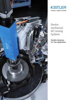


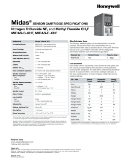
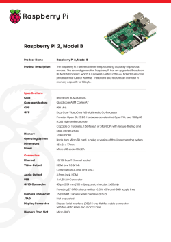
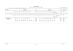
© Copyright 2026