
Solstice Tower Speaker Assembly Manual
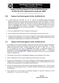
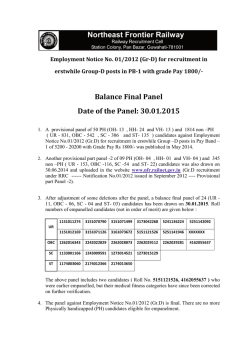
Solstice Kit Assembly Guide
Parts Express
Revision Date: 1/28/2015
Introduction
Parts Express, Morel, and Jeff Bagby would like to thank you for purchasing the Solstice speaker kit!
With this kit, you don't have to be a seasoned speaker builder to enjoy reference-quality speaker
performance. Designed and fine-tuned by expert designer Jeff Bagby, the Solstice speaker features
exceptional coherence, low distortion, and fantastic bass extension. The stylish CNC-cut cabinet makes it
easy to build a furniture-grade piece that you'll be proud to display, and all drivers and crossover parts
are included.
Jeff Bagby writes, "This is honestly one of the best two-way designs I have ever done. I can find very little
to fault. Not only is the response exceptionally flat, but it sounds very balanced, with fantastic resolution
and detail. Vocals are beautiful, as are instruments. Bass is full, extended, and very impressive. Nothing
stands out, it is just sound honest and accurate… It is really a high-end speaker worthy to be compared
with systems that cost several thousand dollars."
Phase 1: Unpacking & preparation
1) Check the contents of the kit package. The Solstice kit package contains everything you need to
build (1) tower speaker; for a pair, two kits are required. The kit package should contain:
a. (1) Rear Panel
b. (2) Top/Bottom Panels
c. (3) Window Braces
d. (1) Port Shelf
e. (2) Side Panels
f. (1) Baffle (front panel)
g. (1) Curved Fascia Panel
h. (2) Morel TiCW 638Nd Titanium Series Hybrid Cu 6" Woofer 8 Ohm (297-105)
i. (1) Morel CAT 308 1-1/8" Soft Dome Tweeter (277-082)
j. (1) Acousta-Stuf Polyfill Speaker Cabinet Sound Damping Material 1 lb. Bag (260-317)
k. (1) Jantzen Audio 0.20 mH 10 AWG Air Core Inductor Crossover Coil (255-210)
l. (1) Jantzen Audio 0.60 mH 10 AWG Air Core Inductor Crossover Coil (255-234)
m. (1) Jantzen Audio 1.0 mH 15 AWG Air Core Inductor Crossover Coil (255-422)
n. (1) Dayton Audio DMPC-6.8 6.8uF 250V Polypropylene Capacitor (027-424)
o. (1) Dayton Audio DMPC-20 20uF 250V Polypropylene Capacitor (027-436)
p. (1) Dayton Audio DNR-25 25 Ohm 10W Precision Audio Grade Resistor (004-25)
q. (1) Dayton Audio DNR-3.0 3 Ohm 10W Precision Audio Grade Resistor (004-3)
You will also need the following tools and items during assembly (not included):
a. Bar clamps (8 or more), 12” in length or greater
b. Yellow wood glue
c. Screwdriver
d. Drill or jigsaw
e. Soldering Iron and solder
f. 2-conductor speaker wire
g. “Fast-on” connectors (optional)
h. Terminal cup or panel (your choice, available from Parts Express)
Phase 2: Assembling the Crossover Network
2) Locate a piece of thin, lightweight material about 4” x 7” in size. Excellent choices include
Masonite, Plexiglass, pegboard, or pre-drilled circuit board material. (Not included in kit.)
3) Arrange the components on the sheet of material so that they can be connected together as
shown in the crossover schematic. Take careful note of the component type and the value of the
component. (The crossover schematic is provided at the end of this Assembly Guide.)
4) Connect the leads of the components as shown in the schematic by twisting them together or
creating interlocking “hooks” with the leads.
5) Double-check that the connections between components are exactly as shown on the
schematic, and that the values of each component match the schematic for the component
shown at that location in the hook-up.
6) Using a hot glue gun or cable ties installed thru drilled holes, secure each component to the
substrate in the final arrangement. Be sure that inductors are not placed close together, and
that one inductor is not visible through the "hole" of any of the other inductors, in order to
minimize interaction between inductors. There is no similar requirement for capacitors or
resistors.
7) With a soldering iron, apply solder to the connections between components. Heat the junction
evenly and verify that the solder flows into the connection rather than forming a "blob" on the
surface (cold joint).
8) Cut two lengths of 2-conductor speaker wire approximately 34”-38” in length, then solder them
at the outputs of the crossover network as shown in the schematic so that the marked polarity
of the wire matches the driver polarity shown in the schematic. Label each wire “woofer” or
“tweeter” corresponding to the schematic.
9) Cut one length of 2-conductor speaker wire approximately 8”-10” in length, and label the length
of wire “Terminals” or “Input”.
Phase 3: Cabinet Assembly and Glue-Up
10) Choose a flat, level work surface. Lay out the parts of the cabinet so that the machined features
of each panel are visible and everything is within easy reach.
11) Locate the enclosure rear panel and place it with the interior surface facing up on the work
surface (dados facing up).
12) Starting with the window brace panels, then proceeding with the port shelf and the top and
bottom panels, apply a thin layer of yellow wood glue to both mating surfaces of the part and
the back panel, and set the pieces in place in their respective dado slots in the rear panel. The
sides of each brace, the port shelf, and the top and bottom panel should be aligned even with
the edges of the raised (non-machined) areas of the panel, and should not interfere with the
side panel dado slots. Carefully wipe away any glue squeeze-out with a paper towel or slightly
damp rag. The window brace with the cutout side should be placed closest to the "top" of the
cabinet; the cutout side provides clearance for the rear of the driver frames.
13) Apply a thin layer of yellow wood glue to the side surfaces of the top and bottom panels, the
window braces, and the port shelf, then apply a thin layer of yellow wood glue to the dado slots
for the side panels and the mating surfaces of each side panel, such that every interface
between two parts will have glue present. If glue is not present, audible cabinet vibrations or air
leaks may occur. Carefully wipe away any glue squeeze-out with a paper towel or slightly damp
rag. Check that all parts of the cabinet except for the rear panel are oriented vertically, and
adjust as needed to avoid skewness in the final assembly.
14) Install two clamps, one at each end of the cabinet, across the two side panels such that the side
panels will be squeezed together. Wipe away any glue squeeze-out between the side panels and
the top/bottom panels of the enclosure.
15) Carefully elevate the enclosure assembly 2-4 inches above the work surface using blocks or
other stable supports, and install four clamps vertically so that they apply pressure between the
side panels and the rear panel. Wipe away any glue squeeze-out between the side panels and
the rear panel of the enclosure.
16) Install two clamps vertically to apply pressure between the top/bottom panels and the rear
panel of the enclosure. Wipe away any glue squeeze-out between the top/bottom panels and
the rear panel of the enclosure.
17) Check one last time that all the panels of the enclosure are square and in alignment with one
another. Adjustments can be made carefully by loosening the clamps on the affected parts.
Panel alignment will affect the ease of finishing the enclosure and the quality of the finish.
18) Allow the glue to dry for several hours or until completely hardened.
19) Flip the cabinet onto its front, so that the back side is facing upward. Measure and mark the
placement of the terminal cup, then cut out the required hole for installation of the terminal
cup. Make sure the terminal cup location will not interfere with the window brace or the port
shelf.
20) Flip the cabinet so that the open end of the cabinet is facing upward. Install the crossover
network (using screws, hot glue, double-sided foam tape, or Velcro) near the cutout for the
terminal cup, so that the wiring will reach the intended components. At this time, insert the
cabinet damping material (polyfill), being sure to expand the material and distribute it evenly
through the entire height of the cabinet. Also at this time, you can also install any other desired
damping materials such as acoustic foam, felt, vinyl sheet, or carpet on the walls of the
enclosure. Make sure the wires for the woofer and tweeter are routed to the top of the cabinet
so they can be reached when the baffle is in place.
21) After all wiring and damping materials are installed inside the cabinet, you are ready to install
the baffle. Apply a thin layer of yellow wood glue to the edges of the side panels, top/bottom
panel, and window braces, then place the baffle onto the cabinet so that the chamfered
(angled) edges of the driver holes face the inside of the cabinet. (The purpose of the chamfers is
to allow the woofers to breathe freely into the cabinet.) The baffle should be installed so that
the drivers are at the opposite end of the cabinet from the port; this is critical to proper bass
performance. Install 4 to 6 clamps vertically so that they apply pressure between the front panel
and the rear panel. Make sure that the baffle is sitting squarely on the cabinet side walls, then
carefully wipe away any glue squeeze-out.
22) Allow the glue to dry for several hours or until completely hardened.
23) Apply the desired finish to the cabinet. The finish may be paint, wood veneer, or another type of
coating. If desired, the curved fascia with driver cutouts may be painted a different color from
the cabinet. You can also experiment with combinations of wood grain veneers to achieve the
desired look. If the finish used for the fascia will be different than that used for the rest of the
cabinet, it is recommended to finish both parts separately, then glue the facia to the front of the
cabinet. The driver mounting screws will reinforce the fascia glue bond and keep it tightly
coupled to the cabinet. Otherwise, if the same color will be used for the entire cabinet, the
fascia may be glued to the cabinet and then all parts may be painted together. Apply a thin layer
of yellow glue to the back side of the fascia, then clamp the fascia in place on the front of the
cabinet, being careful to align the driver holes while clamping. If the cabinet and fascia have
been finished separately, be sure to allow the finish on both pieces to completely cure before
gluing together.
24) Allow the glue to dry for several hours or until completely hardened.
Phase 4: Final Assembly
25) Install the terminal cup or plate by first retrieving the wire labeled "input" or "terminals" from
inside the speaker cabinet, then making the electrical connections to the terminal cup or plate.
Fast-on (spade/lug) terminals may be used, or these connections may be soldered directly.
26) To connect the drivers, retrieve the wiring for the woofers and the tweeter from inside the
cabinet. If desired, install fast-on (spade/lug) terminals at this time. Otherwise, these
connections may be soldered directly. To wire the tweeter, connect the positive wire to the
positive input tab of the tweeter, and connect the negative wire to the negative input tab of the
tweeter. To wire the woofers, first cut a length of 2-conductor speaker wire with a length of
about 10"-12". This wire will be used as a jumper from the positive terminals of the upper
woofer to the positive terminal of the lower woofer, and from the negative terminal of the
upper woofer to the negative terminal of the lower woofer, resulting in both woofers connected
in parallel. Twist the conductors of this wire together with the conductors of the wire labeled
"woofer", matching the positive wire from the crossover with the positive wire on the jumper,
and matching the negative wire from the crossover with the negative wire on the jumper. At this
point, install the fast-on terminals for the woofers (if desired), or solder the connections directly
to the input tabs on each woofer.
27) After wiring the drivers, check the system for proper wiring by first connecting a resistance
meter to the input terminals of the speaker and check that no shorted connections exist – DC
resistance should be greater than zero ohms. Next, check each driver – there should be
continuity, but DC resistance should be greater than zero ohms. Last, connect the system to an
amplifier and play the drivers at a very low volume, listening carefully to each driver to make
sure that the tweeter is only playing treble, and the woofers are only playing midrange. (Bass
may not be audible until the drivers are installed into the enclosure cutouts.)
28) Lower each driver into its corresponding hole in the cabinet and mark the position of the
mounting holes. Next, lift each driver out of the mounting hole and pilot-drill the holes for the
screws that will be used to mount the drivers. This will prevent splitting of the material or
walking of the screw point, and will minimize the possibility of damage to the drivers while
installing screws.
29) Place each driver into its mounting hole and install the mounting screws. Do not over-tighten
the screws – tighten only until firm.
30) You are ready to enjoy your speaker. Congratulations!
Written: R. Buszka
THIS SPACE INTENTIONALLY BLANK
Solstice MLTL Reference Tower Speaker Kit
Crossover Schematic
Crossover Details
Configuration: Two-way
Crossover Frequency: 1.7 kHz
Topology: 4th-order Linkwitz-Riley Acoustical
Woofer Filter: Shaped Third-Order Electrical
Tweeter Filter: Padded Second-Order Electrical
Solstice MLTL Reference Tower Speaker Kit
Enclosure Diagram
Enclosure Details:
Type: Floorstanding
Acoustic Principle: Mass-Loaded Transmission Line
Material: ¾" Medium-Density Fiberboard
Additional Features: Raised driver baffle, window bracing


© Copyright 2026