
Catalog D 15.1 2011
© Siemens AG 2011
Medium-Voltage Air-Cooled Drives
Catalog D 15.1 • 2011
Germany Edition
ROBICON Perfect Harmony
Answers for industry.
© Siemens AG 2011
Related Brochures and Catalogs
ROBICON Perfect Harmony
The Drive of Choice for Highest Demands
(Brochure)
H-compact
Maximun power, minimum size
(Brochure)
E20001-A10-P590-X-7600
E20001-A180-P530-X-7600
ROBICON Perfect Harmony
The Air-Cooled Medium Voltage
Drive of Choice
(Brochure)
H-compact PLUS
Compact, flexible, highest availability
(Brochure)
E20001-A30-P590-X-7600
E20001-A190-P530-X-7600
ROBICON Perfect Harmony
The Water-Cooled Medium Voltage
Drive of Choice
(Brochure)
H-compact
H-compact PLUS
Three-phase Induction Motors
(Catalog D 84.1)
E20001-A40-P590-X-7600
E86060-K5584-A111-A1-7600
SINAMICS GM150 and SINAMICS SM150
The Universal Single-Motor Drive
(Brochure)
E20001-A150-P570-V1-7600
SINAMICS GM150 and SINAMICS SM150
The Reliable Medium-Voltage Drive
with IGCTs
(Brochure)
E20001-A160-P570-X-7600
SINAMICS GM150, SINAMICS SM150
Medium-Voltage Converters
(Catalog D 12)
E86060-K5512-A101-A2-7600
© Siemens AG 2011
ROBICON Perfect Harmony
Medium-Voltage
Air-Cooled Drives
Introduction
1
ROBICON Perfect Harmony
Air-Cooled Drives
2
Technical Data
3
Description of Options
4
Engineering Information
5
Services and Documentation
6
Appendix
7
Catalog D 15.1 · 2011
Germany Edition 1)
© Siemens AG 2011
1) All ROBICON Perfect Harmony medium-voltage
air-cooled drives described in this catalog are
manufactured in our Nuremberg, Germany
location.
Printed on paper
from sustainably
managed forests and
controlled sources.
PEFC/04-31-0835
www.pefc.org
© Siemens AG 2011
Answers for industry.
Siemens Industry answers the challenges in the manufacturing
and the process industry as well as in the building automation
business. Our drive and automation solutions based on Totally
Integrated Automation (TIA) and Totally Integrated Power (TIP)
are employed in all kinds of industry. In the manufacturing
and the process industry. In industrial as well as in functional
buildings.
Siemens offers automation, drive, and
low-voltage switching technology as
well as industrial software from standard products up to entire industry solutions. The industry software enables our
industry customers to optimize the entire value chain – from product design
and development through manufacture
and sales up to after-sales service. Our
electrical and mechanical components
offer integrated technologies for the entire drive train – from couplings to gear
units, from motors to control and drive
solutions for all engineering industries.
Our technology platform TIP offers robust solutions for power distribution.
2
Siemens D 15.1 · 2011
Check out the opportunities our
automation and drive solutions provide.
And discover how you can sustainably
enhance your competitive edge with us.
1
© Siemens AG 2011
ROBICON Perfect Harmony
Introduction
1/2
1/2
Medium-voltage drives
Overview
1/3
1/3
1/3
Perfect harmony of performance
and value
Benefits
Application
1/4
1/4
1/4
1/4
ROBICON Perfect Harmony family
Design
Air-cooled family
Liquid-cooled family
Siemens D 15.1 · 2011
© Siemens AG 2011
Introduction
1
Medium-voltage drives
■ Overview
The reliable and complete range
Medium-voltage
drive series
ROBICON
Perfect Harmony
SINAMICS GM150
(IGBT/IGCT)
SINAMICS SM150
(IGBT/IGCT)
SINAMICS GL150
SINAMICS SL150
Power range
150 kW to 120 MW
800 kW to 17.5 MW
2.8 MW to 31.5 MW
6 MW to 120 MW
3 MW to 36 MW
Application range
General-purpose
applications
General-purpose
applications
Sophisticated
applications
General-purpose
applications
Sophisticated
applications
Motors
Induction and
synchronous motors
Induction and
synchronous motors
Induction and
synchronous motors
Synchronous motors
Induction and
synchronous motors
Energy recovery
–
–
Yes
Yes
Yes
Multi-motor drives
–
–
Yes
–
–
Semiconductor
technology
LV-IGBT
(cell topology)
HV-IGBT/IGCT
(NPC topology)
HV-IGBT/IGCT
(NPC topology)
Thyristor
(LCI topology)
Thyristor
(Cycloconverters)
Typical applications
Pumps, fans,
compressors,
extruders, kneaders,
mixers, crushers,
agitators, conveyor
systems, presses,
ESP, retrofit
Pumps, fans,
compressors,
extruders, kneaders,
mixers, crushers,
agitators, conveyor
systems, marine
drives, presses, wire
rod mills
Rolling mills, mine
hoists, conveyor
systems, test stands
Compressors, fans,
pumps, extruders,
marine drives, starting
drives for blast
furnaces
Rolling mills, mine
hoists, excavators, ore
crushers and cement
mills
The benchmark when it comes to medium-voltage drive
systems
Siemens is the undisputed No. 1 in medium-voltage drives and
around the globe sets the benchmark in this sector – and not
only involving power ratings and market share. Our range of
products is also unique worldwide:
• All voltage classes from 2.3 to 13.8 kV
• A seamless range of power ratings from 150 kW to 120 MW
• All levels of dynamic response and performance
• Single-motor drives and multi-motor systems
• Harmonized and coordinated systems with synchronous and
induction motors
• Motor speeds from 10 to 15,000 rpm in the Megawatt range
The decisive plus when it comes to experience
Everywhere where it involves the highest degree of availability,
an uncountable number of users have been depending on
medium-voltage drives from Siemens since decades – and that
worldwide.
The reason for this lies in the reliability of our drive systems that
has become almost legendary. And all of this didn’t just happen
by chance – it is the result of our many years of experience, our
power of innovation and our extensive know-how.
• From 1969: Variable-speed medium-voltage drive systems
with current-source DC link
• From 1970: Cycloconverters – with more than 700 drives,
Siemens is the global market leader
• 1994: The cell topology of ROBICON Perfect Harmony revolutionized medium-voltage drives
• 1996: "Pioneered" the use of high-rating voltage-source DC
link drives in rolling mills
• 1998: "Pioneered" the use of high-voltage IGBTs for mediumvoltage drives
• 2003: worldwide the highest rating high-speed drives
(65 MW) with LCI for compressors of a gas liquification plant
• 2005: Highest rating drive with voltage-source DC link drives
in a cell-type topology (65/45 MW) used in an LNG plant (LNG
= Liquefied Natural Gas)
1/2
Siemens D 15.1 · 2011
Well-proven as basis
Based on well-proven technological concepts, we are continually developing our medium-voltage drives. The result: Increasingly higher reliability and operational reliability and safety, continually more compact types of construction, continually lower
energy requirement and service and maintenance costs as well
as increasingly simpler handling: from engineering through installation, integration and commissioning up to operator control.
Always the optimum solution
No matter which medium-voltage drive task is involved: We can
always offer the optimum solution. We consequentially utilize the
strengths of various technologies to implement these solutions.
We have the widest range of drives technologies available: From
cycloconverters and load-commutated drives using thyristors
through voltage-source DC link drives equipped with HV-IGBTs
or IGCTs up to cell topology drives. With the latter, a medium
voltage is obtained at the output by connecting low-voltage cells
in series.
© Siemens AG 2011
Introduction
Perfect harmony of performance and value
■ Benefits
According to energy authorities, industrial motors consume over
a billion kilowatt hours of energy each year – fully 50 percent of
the world’s energy usage. System enhancements such as
improved sizing and proper matching to load, more efficient
drive trains, and adjustable speed drives will help drive energy
usage down, according to experts. That means that the right
drive can help you drive cost out of your operation by providing
more precise and efficient control of motors, fans, pumps, and
other devices.
If your process includes motors, fans, or pumps and you haven’t
installed a drive yet, you’re letting thousands of dollars of energy
costs eat away at your bottom line every month because of
process inefficiencies.
■ Application
Siemens can provide a custom-engineered ROBICON Perfect
Harmony drive to maximize your process. We’re the only
company that offers drives from 150 to 60,000 kW. And with an
installed base exceeding more than 2.2 million kW worldwide,
the ROBICON Perfect Harmony is a proven workhorse that can
perform brilliantly for you, too.
A bright future built on a firm foundation
Since its introduction in 1994, the ROBICON Perfect Harmony
drive has revolutionized power conversion and continues to set
industry standards for reliability and innovation. As power
switching device technology advances and increases output
voltage capability, Siemens improves each generation of the
ROBICON Perfect Harmony in three key areas: increased reliability and availability, increased efficiency, and a smaller drive
footprint.
Advances to our product line are made without "reinventing the
wheel" like other drive manufacturers. We have maintained the
ROBICON Perfect Harmony’s core topology and continue to
advance its capability, ensuring life-cycle product support. By
keeping the same topology, our customers see a reduction in
maintenance and spare parts as well as an increase in quality
and lower life-cycle costs. We improve our products by actively
soliciting the input of our customers, and we look forward to
counting you among them.
Siemens drives, the market-leader in medium-voltage air-cooled
drives in the world, deliver an impressive combination of benefits:
• Lower operating costs
• Precise process control
• Lower maintenance costs
• Increased production efficiency
• Exceptional reliability
• Intuitive HMI
The ROBICON Perfect Harmony of today represents an evolution founded on experience garnered from our huge installed
base coupled with Siemens’ unparalleled investments in R&D.
As one of the largest companies in the world, Siemens provides
confidence and financial stability in addition to exceptional technology. We offer you expertise across the globe and a world of
innovation.
The ROBICON Perfect Harmony's™ outstanding record has
made it the drive of choice for demanding applications that
require the highest levels of reliability, precision, and longevity.
Employed in applications ranging from power generation to oil
and gas, water/waste water, and paper production, the
ROBICON Perfect Harmony drive is a versatile performer that
can help you significantly increase productivity, enhance energy
efficiency, and reduce operating costs.
Siemens D 15.1 · 2011
1/3
1
© Siemens AG 2011
Introduction
1
ROBICON Perfect Harmony family
■ Design
The ROBICON Perfect Harmony drive family consists of three
core design configurations, where they are functionally identical
and share a common controller. These three designs are targeted at distinct output power configurations with little overlap
between the frame sizes. The ROBICON Perfect Harmony family
is summarized in the tables below.
Air-cooled family
GenIV
GenIIIe
Power range
0.15 to 2.60 MW (200 to 3500 hp)
1.30 to 5.97 MW (1750 to 8000 hp)
Output voltage
2.3 to 6.6 kV (10/11 kV 1))
2.3 to 7.2 kV
Input voltage
2.4 to 13.8 kV AC (standard), 50/60 Hz
2.4 to 13.8 kV AC (standard), 50/60 Hz
Cooling type
Air-cooled
Air-cooled
Power cell ratings
40, 70, 100, 140, 200 or 260 A at 750 V AC
315, 375, 500 or 660 A at 690 V AC
Liquid-cooled family 1)
WC III
Power range
3 MW to 14.2 MW (4000 to 19000 hp)
Output voltage
2.3 to 8.0 kV
Input voltage
2.4 to 13.8 kV AC (standard) up to 33 kV (option), 50/60 Hz
Cooling type
Liquid-cooled
Power cell ratings
880 or 1250 A at 750 V AC
1)
10/11 kV air-cooled Perfect Harmony drives and liquid-cooled Perfect
Harmony drives are not subject of this catalog, please contact your local
Siemens sales representative for any questions or inquiries.
1/4
Siemens D 15.1 · 2011
2
© Siemens AG 2011
ROBICON Perfect Harmony
Air-Cooled Drives
2/2
2/2
2/2
2/2
2/3
2/5
Introduction
Overview
Benefits
Application
Design
Function
2/8
2/8
2/9
2/10
2/11
2/12
2/13
2/14
2/15
Selection and ordering data
Overview
Motor voltage 2.3/2.4 kV
Motor voltage 3.3 kV
Motor voltage 4.0/4.16 kV
Motor voltage 4.6/4.8 kV
Motor voltage 6.0 kV
Motor voltage 6.6 kV
Order No. supplements
2/18
Options
Siemens D 15.1 · 2011
© Siemens AG 2011
ROBICON Perfect Harmony
Air-Cooled Drives
Introduction
■ Overview
Standards and regulations
The ROBICON Perfect Harmony series drives provide variable
speed operation by converting utility power at fixed frequency
and fixed voltage to variable frequency, variable voltage power.
This conversion is done electronically without moving parts. The
following table shows main characteristics of the ROBICON Perfect Harmony air-cooled generations discussed in this catalog
and the short terms used.
ROBICON Perfect Harmony drives are designed, manufactured
and tested according to applicable NEMA, ANSI, IEEE and IEC
standards.
Overview of generations
Short term
Cell voltage
V
Cell current
A
Cooling
method
Order
numbers
GenIV
750
40 ... 260
Air-cooled
6SR4
GenIIIe
690
315 ... 660
Air-cooled
6SR3
hp
9000
8000
7000
6000
5000
4500
4250
4000
3500
3300
3000
2750
2500
2250
2000
1750
1500
1350
1000
900
750
500
300
200
GenIV
GenIIIe
G_D015_EN_00019
Power
2
ROBICON Perfect Harmony Overview
40
70
100
140
200
260
315
375
500
ROBICON Perfect Harmony drives meet the applicable requirements of the following EU regulations:
• Low-Voltage Directive (LVD)
A Declaration of Conformity and attached CE mark declares
conformity of the low-voltage compartments of the product
(e.g. control cubicle, excitation unit etc.) with LVD 2006/95/EC
or 73/23/EEC (depending on the product) and the associated
standard IEC 61800-5-1, Ed.2
• EMC Directive (EMCD)
A factory certificate declares that the products satisfy the requirements of EMCD 2004/108/EC or 89/336/EEC (depending
on the product) concerning electromagnetic compatibility,
when put to their intended use and conform to the associated
standard IEC 61800-3
• Machinery Directive (MD)
The offered products are intended solely for installation as
components into a machine, system or plant. They are
designed to satisfy the relevant requirements of the standards
IEC 61800-5-1, IEC 60204-1 and IEC 60204-11 to allow the
machine manufacturer or system/plant integrator - by appropriate usage of the products – to meet the requirements of the
Machinery Directive.
Within the European Economic Area (EEA), operation is prohibited until the conformity of the end product with Machinery
Directive 2006/95/EC has been established. It is the sole
responsibility of the machine manufacturer or system/plant
integrator to ensure this.
A 660
Cell current ratings
Power range for ROBICON Perfect Harmony air-cooled drives
■ Benefits
Clean power input
Maximized availability
The ROBICON Perfect Harmony drive:
• Meets the most stringent IEEE 519-1992 requirements for
voltage and current harmonic distortion, even if the source
capacity is no larger than the drive rating 1)
• In most cases eliminates the need for costly and inefficient
harmonic filters and its associated resonance problems
• Protects other on-line equipment from harmonic disturbance
(computers, telephones and other power converters).
The ROBICON Perfect Harmony drive:
• Remains operational in the event of a cell failure by using the
cell bypass option which bypasses the faulted cell
• Offers a Process Tolerant Protection Strategy (ProToPS) based
on a hierarchical warning system that allows the operator to
evaluate the drive disturbance and respond appropriately to
avoid system shutdown.
Power quality output
The ROBICON Perfect Harmony drive provides an integrated
transformer which offers the following additional advantages:
• Simple and robust way to cancel input current harmonics without
the need for input harmonic filters or a complex active front-end
• Protects power converter semiconductors against line transients
• Improves ride-through capabilities
• Completely protects the motor in case of a ground fault in the
converter, the motor cabling or insulation
• Negligible common mode voltage allows the use of a standard
motor eliminating the need for special high-voltage insulation
• Limits the fault energy into the converter in the unlikely event
of a fault
• The incoming service voltage doesn't have to match the motor
voltage.
The ROBICON Perfect Harmony drive:
• Reduces common-mode voltage on the motor stator windings
• Minimizes drive induced torque pulsations and associated
torsional analysis compared to other medium-voltage topologies,
by using a motor friendly pulse width modulation (PWM) output
• Offers sinusoidal output that eliminates additional harmonic
heating and can be used with new or existing motors without
derating.
1)
IEEE 519-1992 compliance can only be guaranteed in networks without
prior disturbances or harmonics already present.
2/2
Siemens D 15.1 · 2011
Extended Reliability
© Siemens AG 2011
ROBICON Perfect Harmony
Air-Cooled Drives
Introduction
■ Benefits (continued)
■ Application
Factory test offers the following advantages:
• Each transformer and converter is tested as a complete
system at full load prior delivery.
• Factory testing allows accurate efficiency measurements to
ensure that drive performance meets customer specifications.
• Verification of sequence of operation and protection functions
Installation and maintenance
• The ROBICON Perfect Harmony drives are easy to install and
maintain.
• Customer needs to provide three cables in and three cables out.
There is no customer site cabling required to connect the assembled sections.
• Power cells can be pulled out easily for maintenance due to
their reduced weight and front accessible connections.
• Sophisticated microprocessor-based diagnostics pinpoint the
location of any defects.
ROBICON Perfect Harmony typical applications
The ROBICON Perfect Harmony is regularly applied by the most
reliability and quality conscious industries and their most
demanding applications, for example:
• Industrial pumps and fans
• Oil & gas pumps and compressors, e.g. electrical submersible pumps (ESPs) and high speed compressors
• Induced and forced draft boiler blowers for power generation
• Clean water and wastewater pumps
• Multi-motor synchronous transfer applications (such as
pipelines in the oil & gas markets).
■ Design
Drive topology
Special
transformer
with 9 isolated
secondaries
Power
cell
A1
Power
cell
B1
G_D015_EN_00009
The ROBICON Perfect Harmony series drives achieve an
uncompromising performance by employing well-proven technology in a modular configuration, as shown in figure "Topology
of ROBICON Perfect Harmony drives (3 cells)". Medium-voltage
levels are obtained by adding together the outputs of multiple
low-voltage power cells. The low-voltage power cells are simplified variations of standard 2-level PWM motor drives for lowvoltage service, which have been built in high volume for many
years.
Power
cell
C1
Input power
3-phase AC
Power
cell
A2
Power
cell
B2
Power
cell
C2
Power
cell
A3
For higher output voltage capabilities, the ROBICON Perfect
Harmony topology would be extended to have up to 5 power
cells in series in each phase (in case of a GenIV drive 1)), with
additional secondary windings (number of secondaries equals
number of power cells) on the integral isolation transformer.
Each power cell is capable of receiving input power at
750 V AC 2), 3-phase, 50/60 Hz and delivering that power to a
single phase load at a variable frequency from 0.5 to the maximum rated output frequency of the drive.
Transformer
The transformer is an integral part of the drive and cannot be
specified or obtained separately. It has been carefully designed
over several generations to function properly with the ROBICON
Perfect Harmony drive.
ROBICON Perfect Harmony transformers are dry-type forcedair. They are designed specifically for use with a particular
ROBICON Perfect Harmony drive and have 9 to 18 extended
delta secondaries. The secondary currents are rich in harmonics, but the primary current is virtually sinusoidal. It is very important to recognize that this is no ordinary transformer which can
be obtained as an off-the-shelf item. The usual standards,
ANSI C57-12.51 and C57-12.91 (optionally IEC 60076-11:2004),
apply to transformers with only a few windings and which are
subjected to sinusoidal currents. Thus, there are some important
exceptions and modifications to the application of these
standards to ROBICON Perfect Harmony transformers.
Proven IGBTs
Power
cell
B3
Power
cell
C3
Motor
Insulated Gate Bipolar Transistors (IGBTs) form the backbone of
the ROBICON Perfect Harmony drive. Built in high volumes and
serving as a proven power device across the industrial power
control industry, IGBT technology has been in existence for more
than a decade. The stability and availability of IGBTs give reliable, long-term, life-cycle confidence.
Topology of ROBICON Perfect Harmony drives (3 cells)
1)
Up to 6 power cells in series in each phase in case of a GenIIIe drive.
2)
690 V AC in case of a GenIIIe power cell.
Siemens D 15.1 · 2011
2/3
2
© Siemens AG 2011
ROBICON Perfect Harmony
Air-Cooled Drives
Introduction
■ Design (continued)
Linked low-voltage cells
A
15 module drive with
no modules bypassed.
100 % of the modules
are in use.
100 % of full voltage
is available.
A5
A4
A3
A2
VAC
V BA
A1
IGBTs Q1-Q4
Q1
120°
Q3
C1 N B1
C2
T2
1
2
+
3
B2
C5
+
T1
Q2
Power
output
of cell
B3
C4
B4
C5
B5
C
B
VCB
G_D015_EN_00013
Dedicated
winding on
power
transformer
Q4
Simplified diagram of a 15 cell drive
Fiber optic
signals
to and from
master control
A
15 module drive after
bypass of 2 modules
in phase A.
A3
A2
Schematic of a typical power cell
Advanced cell bypass
Since the cells in each phase of a ROBICON Perfect Harmony
drive are in series, bypassing a cell has no effect on the current
capability of the drive, but the voltage capability will be reduced.
Usually the required motor voltage is roughly proportional to
speed, so that the maximum speed at which the drive can fulfill
the application requirements will also be reduced.
Therefore, it is important to maximize the motor voltage available
after one or more cells have been bypassed. The following
figures illustrate the voltage available from a ROBICON Perfect
Harmony drive, where the cells, represented by circles, are
shown as simple voltage sources. The following figure shows a
15-cell drive in which no cells are bypassed. With 100 % of the
cells in use, 100 % of the original voltage is available. The
voltage commands to the three phase groups of cells will have
phase A displaced from phase B by 120°, and from phase C by
120°.
A1
VAC
The ROBICON Perfect Harmony is designed to withstand
failures that would overwhelm conventional drives because
redundancy options are added into the system. The patented,
cell-based configuration maximizes uptime and simplifies
modifications.
Through a redundant bypass control that is completely separated from each power cell, the ROBICON Perfect Harmony
ensures automatic bypass of a failed power cell in less than
500 ms.
87 % of the modules
are in use, but the
output voltage is
available unbalanced.
120°
V BA
C1 N B1
C2
B2
C3
B3
C4
B4
C5
B5
C
B
VCB
Drive output with 2 cells bypassed in phase A
One possible remedy is to bypass an equal number of cells in all
three phases, even though some may not have faulted. The
following figure illustrates this approach. Obviously, this method
prevents unbalance but sacrifices possible voltage capability. In
this figure, 87 % of the cells are functional, but only 60 % are in
use, and only 60 % of full voltage is available.
A
15 module drive after
bypass of 2 modules
in all phases.
Balance is restored.
87 % of the modules
are OK, but only
60 % are in use.
60 % of full voltage
is available.
A3
A2
VAC
A1
C1
N
C2
C
V BA
120°
B1
B2
C3
B3
VCB
Drive output re-balanced by bypassing functional cells
2/4
Siemens D 15.1 · 2011
G_D015_EN_00014
Local control circuits
When two cells are bypassed in phase A, the output voltage will
tend to become unbalanced, as illustrated in the figure below.
B
G_D015_EN_00007
Local
control
power
G_D015_EN_00010
2
In the ROBICON Perfect Harmony, a series of low-voltage cells
(see figure "schematic of a typical power cell") are linked
together to build the medium-voltage power output of the drive
system. This patented modular configuration gives the
ROBICON Perfect Harmony many advantages when it comes to
maintenance, power quality and reliability. It also provides the
basis for one of its most important advantages – increased
availability through the advanced cell bypass option.
© Siemens AG 2011
ROBICON Perfect Harmony
Air-Cooled Drives
Introduction
■ Design (continued)
A
15 module drive after
bypass of 2 modules
in phase A only
and adjustment of
phase angles.
87 % of the modules
are in use.
80 % of full voltage
is available.
A3
A2
Siemens calls this approach Neutral Shift. This approach is
equivalent to introducing a zero-sequence component into the
voltage command vectors for the cells. In the figure below, the
full remaining 87 % of functional cells are in use, and 80 % of the
original voltage is available. The phase angles of the cell
voltages have been adjusted so that phase A is displaced from
phase B and from phase C by 132.5°, instead of the normal
120°.
132.5°
VAC
A1
C1
C2
2
132.5°
V BA
B1
95°
C3
B2
B3
C4
B4
B5
C5
C
G_D015_EN_00008
A better approach is illustrated in the figure on the right. This
method takes advantage of the fact that the star-point of the cells
is floating, and is not connected to the neutral of the motor.
Therefore the star-point can be shifted away from the motor neutral, and the phase angles of the cell voltages can be adjusted,
so that a balanced set of motor voltages is obtained even though
the cell group voltages are not balanced.
VCB
B
Drive output re-balanced by adjusting phase angles (Neutral Shift)
■ Function
Control, protection and monitoring functions
Closed-loop control
The drive can be controlled by means of vector control algorithm without an encoder (standard) or with it
(option).
Auto tuning
Auto tuning involves the estimation of motor parameters required for motor control. This is done in two
stages. In stage one, motor stator resistance and total leakage inductance are determined. This stage
does not require spinning the motor. In stage two, the motor no-load current and total inertia are
estimated. Estimation of these values requires the motor be spun. Accuracy of the estimation is better if
the load is de-coupled from the motor.
Automatic restart
The automatic restart switches the drive on again when the power is restored after a power failure or a
general fault, and ramps up to the current speed setpoint.
Energy saver
Energy saver control allows the reduction of motor losses, and improves overall efficiency, when the
demanded motor load is low. Depending on the motor load, the control will reduce motor flux.
As motor load increases, the control will increase motor flux.
Flying restart
The flying restart function permits smooth connection of the drive to a rotating motor.
Diagnostics functions
• Self-diagnosis of control hardware
• Non-volatile memory for reliable diagnosis when the power supply fails
• Monitoring of IGBTs with individual messages for each cell
• User-friendly local operator panel with plain text messages
• Fault log with first-in indication and time/date stamp
User configurable digital meters
The user can select indication of speed, voltage, current, input/output power, and efficiency on the
operator panel.
Process control system
The optional Process Tolerant Protection Strategy (ProToPS) is a groundbreaking process control system
available exclusively from Siemens. Instead of tripping the drive and automatically shutting down the
system due to a malfunction, ProToPS provides a hierarchical system of warnings. This control strategy
allows time to evaluate the situation and respond appropriately to avoid a system shutdown.
Operating hours and switching cycle
counter
The amount of the time that the drive was operational since it was commissioned can be displayed.
The switching cycle counter can be generated by means of an event log from the drive controller.
Detection of actual motor speed
The control algorithm calculates actual motor speed from currents and voltages measured at the drive
output.
Emergency stop button
The drives are equipped as standard with an Emergency Stop button (red mushroom button with yellow
collar) which is fitted in the cabinet door. The contacts of the pushbutton are connected in parallel to the
terminal block so they can be integrated in a protection concept on the plant side.
Insulation monitoring
An output signal can be provided optional to operate the customer protection.
I/O monitoring
I/O signals allow user-customization of the system and they can be monitored remotely or by using the
operator panel display.
Thermal overload protection
Based on the output signals of the drive the thermal motor model is calculated. The motor thermal
overload protection algorithm prevents the motor from being exposed to excessive temperatures.
Siemens D 15.1 · 2011
2/5
© Siemens AG 2011
ROBICON Perfect Harmony
Air-Cooled Drives
Introduction
■ Function (continued)
GenIV
GenIV is the fourth generation of forced air-cooled mediumvoltage, voltage source inverter drives offered in the patented
ROBICON Perfect Harmony topology, together with NXGII
controller.
2
The GenIV is a series of adjustable speed AC motor drives
presently available in 2300 to 6600 V outputs, and loads ranging
from 0.15 to 2.60 MW (200 to 3500 hp). Six power cell amperage
types are available: 40, 70, 100, 140, 200 and 260. Drives in this
product series provide an efficient, cost effective, and reliable
method of adjusting the speed of an AC motor. The core unit
contains a wide range of expandable features, enabling it to
meet the demands of many types of industrial applications.
ROBICON Perfect Harmony GenIV (4.0 kV)
ROBICON Perfect Harmony GenIV characteristics
Power semiconductors
IGBTs, diodes
Line-side rectifier
18- to 30-pulse diode rectifier
Multi-level drive (PWM) with IGBT power modules
Motor-side inverter
Power cell ratings
A
40, 70, 100, 140, 200, 260 at 750 V
Input voltage range
kV
2.3 to 13.8
±10 % of nominal rated input voltage
Input voltage tolerance
Input frequency
Hz
50/60 ± 5 %
Input power factor
≥ 0.95 above 10 % load
Input harmonics
≤ 5 % TDD
Output voltages
kV
2.3/2.4, 3.3, 4.0/4.16, 6.0, 6.6
Output frequency and drift
Hz
0.5 ... 330 ± 0.5 %
Output torque
Hz
10 ... 167 rated torque (2-quadrant)
Output dV/dt
V/μs
< 3000
Power range
MW
0.15 to 2.60 (200 to 3500 hp)
Cooling methods
Forced air-cooled
Control
NXGII
Motor control
• Induction motor control
• Synchronous motor control
• Permanent magnet motors
• Wound rotor motors
GenIV cell overload capability
Required overload
(I/IN)
Available continuous output current per cell
A
No overload
40
70
100
140
200
260
110 %
(for 1 min, cycle time 10 min)
40
70
100
140
200
260
150 %
(for 1 min, cycle time 10 min)
40
70
100
140 1)
200
260
The GenIV drives as standard provide a 150 % overload capability for all cell ratings without any derating.
1)
The available continuous rating of 140 A will reduce to 130 A when
operated at or above 45 °C ambient temperature.
2/6
Siemens D 15.1 · 2011
© Siemens AG 2011
ROBICON Perfect Harmony
Air-Cooled Drives
Introduction
■ Function (continued)
GenIIIe
GenIIIe is the third generation of forced air-cooled mediumvoltage pulse width modulated variable frequency motor drives,
offered in the patented ROBICON Perfect Harmony power topology in concert with proprietary NXGII hardware control platform
and embedded software. GenIIIe is an extension of the GenIII
series offering a higher current rating.
The GenIIIe is a series of adjustable speed AC motor drives
presently available in an output voltage range from 2.3 kV to
7.2 kV, and loads ranging from 1.30 to 5.97 MW (3000 to
9000 hp). Four power cell amperage types are available: 315,
375, 500, and 660 A at 690 V AC.
ROBICON Perfect Harmony GenIIIe
ROBICON Perfect Harmony GenIIIe, characteristics
Power semiconductors
IGBTs, diodes
Line-side rectifier
18 to 36-pulse diode rectifier
Multi-level drive (PWM) with IGBT power modules
Motor-side inverter
Power cell ratings
A
315, 375, 500, 660 at 690 V
Input voltage range
kV
2.3 to 13.8
±10 % of nominal rated input voltage
Input voltage tolerance
Input frequency
Hz
50/60 ± 5 %
Input power factor
≥ 0.95 above 10 % load
Input harmonics
≤ 5 % TDD
Output voltages
kV
2.3/2.4, 3.3, 4.16, 4.6/4.8, 6.0, 6.6, 7.2
Output frequency and drift
Hz
0.5 ... 330 ± 0.5 %
Output torque
Hz
10 ... 167 rated torque (2-quadrant)
Output dV/dt
V/μs
< 1000
Power range
MW
1.30 to 5.97 (1750 to 8000 hp)
Cooling method
Forced air-cooled
Control
NXGII
Motor control
• Induction motor control
• Synchronous motor control
• Permanent magnet motors
• Wound rotor motors
Note:
Not all configurations of output voltages and/or power cell amperage might be available from Nuremberg factory.
See selection and ordering data in this section for details.
GenIIIe cell overload capability
Required overload
(I/IN)
Available continuous output current per cell
A
No overload
315
375
500
660
110 %
(for 1 min, cycle time 10 min)
315
375
500
660
150 %
(for 1 min, cycle time 10 min)
300
300
400
450
The GenIIIe drives as standard provide a 110 % overload capability for all cell ratings without any derating.
Siemens D 15.1 · 2011
2/7
2
© Siemens AG 2011
ROBICON Perfect Harmony
Air-Cooled Drives
Selection and ordering data
■ Overview
The following tables help you to select the right converter type
and give an overview of the corresponding motor data and order
numbers. The tables are organized according to the motor
voltages. For the complete technical data of the listed converter
types refer to chapter 3.
2
In order to select the right ROBICON Perfect Harmony drive,
please take into consideration the following steps:
Step 1 – Choosing the right cell size
1.1 Determine the maximum continuous motor current, temporary overload not included:
• Use the motor full load line current (FLA) if available or use
the following formula to calculate motor current I.
I=
Pmotor _ kW
冑 3 × Vmotor
× PFmotor × ηmotor
where,
Pmotor_kW = output (in kW)
Vmotor
= motor voltage
PFmotor
= motor power factor (= (cos ϕ)motor)
ηmotor
= motor efficiency
(keeping in mind: motor service factor if utilized and/or
overload requirements)
• If the motor power factor (PFmotor) and efficiency at full load
are not known then use the following default values:
- PFmotor = 0.88
- ηmotor = 0.94 for power cells up to 140 A
0.964 for power cells above 140 A
• Factor in the motor service factor (SF) if the application will
make use of it under long term operation. You do so by
multiplying the given/calculated current (from step 1.1) by
the motor SF.
1.2 Determine the minimum continuous cell current rating:
If the drive is intended to operate within nominal parameters, the maximum continuous motor current will be the
minimum continuous cell current rating. For the appropriate
converter type, identify the smallest cell available that can
source the current calculated in the previous paragraph.
2/8
Siemens D 15.1 · 2011
1.3 Factor in any overload requirements:
• For the cell chosen on the previous paragraph, make sure it
can handle the application overload requirements by
checking overload capabilities (see pages 2/6 and 2/7)
• If the overload requirements exceed the capabilities of the
chosen cell then the next cell size must be selected.
Step 2 – Choosing the right transformer
2.1 The ROBICON Perfect Harmony transformer rating is based
on the motor shaft horsepower:
• If the drive is intended to operate within nominal parameters
and without added redundant cells, the maximum continuous motor horsepower (hp) will be used to rate the transformer using a straight formula:
1 transformer kVA per each motor hp
• The above rule is followed regardless of motor type.
2.2 The transformer is designed to support the temporary overloads associated with the cells it feeds. If those levels are
exceeded by the application requirements, please contact
the factory or your local Siemens sales representative.
Note:
Please contact the factory or your local Siemens sales representative for derating calculations, if the drive is intended to operate
outside the nominal conditions such as:
• High ambient temperatures
• High altitude installations
• Very low continuous operating frequencies at high current
• High frequency operation for high speed motors.
© Siemens AG 2011
ROBICON Perfect Harmony
Air-Cooled Drives
Selection and ordering data
■ Selection and ordering data
Motor voltage 2.3/2.4 kV
Motor
voltage
Type rating Shaft
output 1)
Shaft
output 1)
Typical
motor
current 1)
Power cell
current
kV
kVA
hp
A
A
kW
Number of Transformer Order number
cells
rating
Generation
kVA
2.4
180
149
200
43
70
9
200
6SR4102-0 ■ B32-0 ■ ■ 0
GenIV
2.4
270
224
300
65
70
9
300
6SR4102-0 ■ B33-0 ■ ■ 0
GenIV
2.4
290
241
323
70
70
9
400
6SR4102-0 ■ B34-0 ■ ■ 0
GenIV
2.4
360
298
400
87
100
9
400
6SR4102-0 ■ C34-0 ■ ■ 0
GenIV
2.4
410
336
450
98
100
9
450
6SR4102-0 ■ C34-5 ■ ■ 0
GenIV
2.4
415
344
461
100
100
9
500
6SR4102-0 ■ C35-0 ■ ■ 0
GenIV
2.4
450
373
500
108
140
9
500
6SR4102-0 ■ D35-0 ■ ■ 0
GenIV
2.4
540
448
600
130
140
9
600
6SR4102-0 ■ D36-0 ■ ■ 0
GenIV
2.4
580
481
645
140
140
9
700
6SR4102-0 ■ D37-0 ■ ■ 0
GenIV
2.4
1305
1111
1489
315
315
9
1750
6SR3102-1 ■ G41-7■ ■ 0
GenIIIe
2.4
1540
1306
1750
370
375
9
1750
6SR3102-1 ■ H41-7 ■ ■ 0
GenIIIe
2.4
1555
1322
1773
375
375
9
2000
6SR3102-1 ■ H42-0 ■ ■ 0
GenIIIe
2.4
1760
1492
2000
423
500
9
2000
6SR3102-1 ■ J42-0 ■ ■ 0
GenIIIe
2.4
1980
1679
2250
476
500
9
2250
6SR3102-1 ■ J42-2 ■ ■ 0
GenIIIe
2.4
2075
1763
2363
500
500
9
2500
6SR3102-1 ■ J42-5 ■ ■ 0
GenIIIe
2.4
2200
1865
2500
529
660
9
2500
6SR3102-1 ■ K42-5 ■ ■ 0
GenIIIe
2.4
2620
2222
2978
630
660
9
3000
6SR3102-1 ■ K43-0 ■ ■ 0
GenIIIe
For order number supplements see pages 2/15 to 2/17
1)
The specifications for the typical motor current and the power data in hp
and kW are approximate values only; these have been calculated for operation with induction motors and for a typical power factor cos ϕ and motor
efficiency. Both approximate values have to be adapted to the motor that is
actually used.
Siemens D 15.1 · 2011
2/9
2
© Siemens AG 2011
ROBICON Perfect Harmony
Air-Cooled Drives
Selection and ordering data
■ Selection and ordering data (continued)
Motor voltage 3.3 kV
2
Motor
voltage
Type rating Shaft
output 1)
Shaft
output 1)
Typical
motor
current 1)
Power cell
current
kV
kVA
hp
A
A
kW
Number of Transformer Order number
cells
rating
Generation
kVA
3.3
180
149
200
32
40
9
200
6SR4102-0 ■ A32-0 ■ ■ 0
GenIV
3.3
225
189
254
40
40
9
300
6SR4102-0 ■ A33-0 ■ ■ 0
GenIV
3.3
270
224
300
47
70
9
300
6SR4102-0 ■ B33-0 ■ ■ 0
GenIV
3.3
360
298
400
63
70
9
400
6SR4102-0 ■ B34-0 ■ ■ 0
GenIV
3.3
400
331
444
70
70
9
450
6SR4102-0 ■ B34-5 ■ ■ 0
GenIV
3.3
410
336
450
71
100
9
450
6SR4102-0 ■ C34-5 ■ ■ 0
GenIV
3.3
450
373
500
79
100
9
500
6SR4102-0 ■ C35-0 ■ ■ 0
GenIV
3.3
540
448
600
95
100
9
600
6SR4102-0 ■ C36-0 ■ ■ 0
GenIV
3.3
570
473
634
100
100
9
700
6SR4102-0 ■ C37-0 ■ ■ 0
GenIV
3.3
630
522
700
110
140
9
700
6SR4102-0 ■ D37-0 ■ ■ 0
GenIV
3.3
720
597
800
126
140
9
800
6SR4102-0 ■ D38-0 ■ ■ 0
GenIV
3.3
800
662
887
140
140
9
900
6SR4102-0 ■ D38-7 ■ ■ 0
GenIV
3.3
1540
1306
1750
269
315
9
1750
6SR3102-1 ■ G41-7■ ■ 0
GenIIIe
3.3
1760
1492
2000
308
315
9
2000
6SR3102-1 ■ G42-0■ ■ 0
GenIIIe
3.3
1800
1527
2047
315
315
9
2250
6SR3102-1 ■ G42-2■ ■ 0
GenIIIe
3.3
1980
1679
2250
346
375
9
2250
6SR3102-1 ■ H42-2 ■ ■ 0
GenIIIe
3.3
2140
1818
2437
375
375
9
2500
6SR3102-1 ■ H42-5 ■ ■ 0
GenIIIe
3.3
2200
1865
2500
385
500
9
2500
6SR3102-1 ■ J42-5 ■ ■ 0
GenIIIe
3.3
2640
2238
3000
462
500
9
3000
6SR3102-1 ■ J43-0 ■ ■ 0
GenIIIe
3.3
2855
2424
3250
500
500
9
3500
6SR3102-1 ■ J43-5 ■ ■ 0
GenIIIe
3.3
3080
2611
3500
539
660
9
3500
6SR3102-1 ■ K43-5 ■ ■ 0
GenIIIe
For order number supplements see pages 2/15 to 2/17
1)
The specifications for the typical motor current and the power data in hp
and kW are approximate values only; these have been calculated for operation with induction motors and for a typical power factor cos ϕ and motor
efficiency. Both approximate values have to be adapted to the motor that is
actually used.
2/10
Siemens D 15.1 · 2011
© Siemens AG 2011
ROBICON Perfect Harmony
Air-Cooled Drives
Selection and ordering data
■ Selection and ordering data (continued)
Motor voltage 4.0/4.16 kV
Motor
voltage
Type rating Shaft
output 1)
Shaft
output 1)
Typical
motor
current 1)
Power cell
current
kV
kVA
hp
A
A
kW
Number of Transformer Order number
cells
rating
Generation
kVA
4.0/4.16 2)
180
149
200
26
40
9
200
6SR4102-0 ■ A32-0 ■ ■ 0
GenIV
4.0/4.16 2)
270
224
300
39
40
9
300
6SR4102-0 ■ A33-0 ■ ■ 0
GenIV
4.0/4.16 2)
275
229
307
40
40
9
400
6SR4102-0 ■ A34-0 ■ ■ 0
GenIV
4.0/4.16 2)
360
298
400
52
70
9
400
6SR4102-0 ■ B34-0 ■ ■ 0
GenIV
4.0/4.16 2)
410
336
450
59
70
9
450
6SR4102-0 ■ B34-5 ■ ■ 0
GenIV
4.0/4.16 2)
450
373
500
65
70
9
500
6SR4102-0 ■ B35-0 ■ ■ 0
GenIV
4.0/4.16 2)
480
401
538
70
70
9
600
6SR4102-0 ■ B36-0 ■ ■ 0
GenIV
4.0/4.16 2)
540
448
600
78
100
9
600
6SR4102-0 ■ C36-0 ■ ■ 0
GenIV
4.0/4.16 2)
630
522
700
91
100
9
700
6SR4102-0 ■ C37-0 ■ ■ 0
GenIV
4.0/4.16 2)
690
573
768
100
100
9
800
6SR4102-0 ■ C38-0 ■ ■ 0
GenIV
4.0/4.16 2)
720
597
800
104
140
9
800
6SR4102-0 ■ D38-0 ■ ■ 0
GenIV
4.0/4.16 2)
810
671
900
117
140
9
900
6SR4102-0 ■ D38-7 ■ ■ 0
GenIV
4.0/4.16 2)
900
746
1000
130
140
9
1000
6SR4102-0 ■ D41-0 ■ ■ 0
GenIV
4.0/4.16 2)
965
802
1075
140
140
9
1100
6SR4102-0 ■ D41-1 ■ ■ 0
GenIV
4.16
1980
1679
2250
275
315
12
2250
6SR3102-3 ■ G42-2■ ■ 0
GenIIIe
4.16
2200
1865
2500
305
315
12
2500
6SR3102-3 ■ G42-5■ ■ 0
GenIIIe
4.16
2265
1925
2581
315
315
12
3000
6SR3102-3 ■ G43-0■ ■ 0
GenIIIe
4.16
2640
2238
3000
366
375
12
3000
6SR3102-3 ■ H43-0 ■ ■ 0
GenIIIe
4.16
2700
2292
3073
375
375
12
3500
6SR3102-3 ■ H43-5 ■ ■ 0
GenIIIe
4.16
3080
2611
3500
427
500
12
3500
6SR3102-3 ■ J43-5 ■ ■ 0
GenIIIe
4.16
3520
2984
4000
488
500
12
4000
6SR3102-3 ■ J44-0 ■ ■ 0
GenIIIe
4.16
3600
3056
4097
500
500
12
5000
6SR3102-3 ■ J45-0 ■ ■ 0
GenIIIe
4.16
4400
3730
5000
610
660
12
5000
6SR3102-3 ■ K45-0 ■ ■ 0
GenIIIe
4.16
4540
3851
5162
630
660
12
6000
6SR3102-3 ■ K46-0 ■ ■ 0
GenIIIe
For order number supplements see pages 2/15 to 2/17
1)
The specifications for the typical motor current and the power data in hp
and kW are approximate values only; these have been calculated for operation with induction motors and for a typical power factor cos ϕ and motor
efficiency. Both approximate values have to be adapted to the motor that is
actually used.
2)
4.16 kV possible with overmodulation; under load, motor is run at 4.0 kV.
Siemens D 15.1 · 2011
2/11
2
© Siemens AG 2011
ROBICON Perfect Harmony
Air-Cooled Drives
Selection and ordering data
■ Selection and ordering data (continued)
Motor voltage 4.6/4.8 kV
2
Motor
voltage
Type
rating
Shaft
output 1)
Shaft
output 1)
Typical
motor
current 1)
Power
cell
current
Order number
Generation
kV
kVA
kW
hp
A
A
4.8
2200
1865
2500
264
315
12
4.8
2615
2222
2978
315
315
12
2500
6SR3102-3 ■ G42-5■ ■ 0
GenIIIe
3000
6SR3102-3 ■ G43-0■ ■ 0
GenIIIe
4.8
2640
2238
3000
317
375
12
4.8
3080
2611
3500
370
375
12
3000
6SR3102-3 ■ H43-0 ■ ■ 0
GenIIIe
3500
6SR3102-3 ■ H43-5 ■ ■ 0
4.8
3115
2645
3545
375
375
GenIIIe
12
4000
6SR3102-3 ■ H44-0 ■ ■ 0
4.8
3520
2984
4000
423
GenIIIe
500
12
4000
6SR3102-3 ■ J44-0 ■ ■ 0
4.8
4155
3526
4727
GenIIIe
500
500
12
5000
6SR3102-3 ■ J45-0 ■ ■ 0
4.8
4400
3730
GenIIIe
5000
529
660
12
5000
6SR3102-3 ■ K45-0 ■ ■ 0
GenIIIe
4.8
5240
4443
5956
630
660
12
6000
6SR3102-3 ■ K46-0 ■ ■ 0
GenIIIe
For order number supplements see pages 2/15 to 2/17
1)
The specifications for the typical motor current and the power data in hp
and kW are approximate values only; these have been calculated for operation with induction motors and for a typical power factor cos ϕ and motor
efficiency. Both approximate values have to be adapted to the motor that is
actually used.
2/12
Siemens D 15.1 · 2011
Number
of cells
Transformer
rating
kVA
© Siemens AG 2011
ROBICON Perfect Harmony
Air-Cooled Drives
Selection and ordering data
■ Selection and ordering data (continued)
Motor voltage 6.0 kV
Motor
voltage
Type rating Shaft
output 1)
Shaft
output 1)
Typical
motor
current 1)
Power cell
current
kV
kVA
hp
A
A
kW
Number of Transformer Order number
cells
rating
Generation
kVA
6.0
270
224
300
26
40
15
300
6SR4102-2 ■ A33-0 ■ ■ 0
GenIV
6.0
360
298
400
35
40
15
400
6SR4102-2 ■ A34-0 ■ ■ 0
GenIV
6.0
415
344
461
40
40
15
500
6SR4102-2 ■ A35-0 ■ ■ 0
GenIV
6.0
450
373
500
43
70
15
500
6SR4102-2 ■ B35-0 ■ ■ 0
GenIV
6.0
540
448
600
52
70
15
600
6SR4102-2 ■ B36-0 ■ ■ 0
GenIV
6.0
630
522
700
61
70
15
700
6SR4102-2 ■ B37-0 ■ ■ 0
GenIV
6.0
720
597
800
69
70
15
800
6SR4102-2 ■ B38-0 ■ ■ 0
GenIV
6.0
725
602
807
70
70
15
900
6SR4102-2 ■ B38-7 ■ ■ 0
GenIV
6.0
810
671
900
78
100
15
900
6SR4102-2 ■ C38-7 ■ ■ 0
GenIV
6.0
900
746
1000
87
100
15
1000
6SR4102-2 ■ C41-0 ■ ■ 0
GenIV
6.0
1035
860
1152
100
100
15
1250
6SR4102-2 ■ C41-2 ■ ■ 0
GenIV
6.0
1130
933
1250
108
140
15
1250
6SR4102-2 ■ D41-2 ■ ■ 0
GenIV
6.0
1350
1119
1500
130
140
15
1500
6SR4102-2 ■ D41-5 ■ ■ 0
GenIV
6.0
1450
1203
1613
140
140
15
1750
6SR4102-2 ■ D41-7 ■ ■ 0
GenIV
6.0
1540
1306
1750
148
200
15
1750
6SR4102-2 ■ E41-7 ■ ■ 0
GenIV
6.0
1760
1492
2000
169
200
15
2000
6SR4102-2 ■ E42-0 ■ ■ 0
GenIV
6.0
1980
1679
2250
190
200
15
2250
6SR4102-2 ■ E42-2 ■ ■ 0
GenIV
6.0
2075
1763
2363
200
200
15
2500
6SR4102-2 ■ E42-5 ■ ■ 0
GenIV
6.0
2200
1865
2500
212
260
15
2500
6SR4102-2 ■ F42-5 ■ ■ 0
GenIV
6.0
2640
2238
3000
254
260
15
3000
6SR4102-2 ■ F43-0 ■ ■ 0
GenIV
6.0
2700
2292
3073
260
260
15
3500
6SR4102-2 ■ F43-5 ■ ■ 0
GenIV
6.0
3080
2611
3500
296
315
15
3500
6SR3102-5 ■ G43-5■ ■ 0
GenIIIe
6.0
3270
2777
3722
315
315
15
4000
6SR3102-5 ■ G44-0■ ■ 0
GenIIIe
6.0
3520
2984
4000
338
375
15
4000
6SR3102-5 ■ H44-0 ■ ■ 0
GenIIIe
6.0
3895
3306
4432
375
375
15
5000
6SR3102-5 ■ H45-0 ■ ■ 0
GenIIIe
6.0
4400
3730
5000
423
500
15
5000
6SR3102-5 ■ J45-0 ■ ■ 0
GenIIIe
6.0
5195
4408
5909
500
500
15
6000
6SR3102-5 ■ J46-0 ■ ■ 0
GenIIIe
6.0
5280
4476
6000
508
660
15
6000
6SR3102-5 ■ K46-0 ■ ■ 0
GenIIIe
6.0
6160
5222
7000
592
660
15
7000
6SR3102-5 ■ K47-0 ■ ■ 0
GenIIIe
6.0
6550
5554
7445
630
660
15
8000
6SR3102-5 ■ K48-0 ■ ■ 0
GenIIIe
For order number supplements see pages 2/15 to 2/17
1)
The specifications for the typical motor current and the power data in hp
and kW are approximate values only; these have been calculated for operation with induction motors and for a typical power factor cos ϕ and motor
efficiency. Both approximate values have to be adapted to the motor that is
actually used.
Siemens D 15.1 · 2011
2/13
2
© Siemens AG 2011
ROBICON Perfect Harmony
Air-Cooled Drives
Selection and ordering data
■ Selection and ordering data (continued)
Motor voltage 6.6 kV
2
Motor
voltage
Type rating Shaft
output 1)
Shaft
output 1)
Typical
motor
current 1)
Power cell
current
kV
kVA
hp
A
A
kW
Number of Transformer Order number
cells
rating
Generation
kVA
6.6
270
224
300
24
40
15
300
6SR4102-2 ■ A33-0 ■ ■ 0
GenIV
6.6
360
298
400
32
40
15
400
6SR4102-2 ■ A34-0 ■ ■ 0
GenIV
6.6
450
373
500
39
40
15
500
6SR4102-2 ■ A35-0 ■ ■ 0
GenIV
6.6
455
378
507
40
40
15
600
6SR4102-2 ■ A36-0 ■ ■ 0
GenIV
6.6
540
448
600
47
70
15
600
6SR4102-2 ■ B36-0 ■ ■ 0
GenIV
6.6
630
522
700
55
70
15
700
6SR4102-2 ■ B37-0 ■ ■ 0
GenIV
6.6
720
597
800
63
70
15
800
6SR4102-2 ■ B38-0 ■ ■ 0
GenIV
6.6
800
662
887
70
70
15
900
6SR4102-2 ■ B38-7 ■ ■ 0
GenIV
6.6
810
671
900
71
100
15
900
6SR4102-2 ■ C38-7 ■ ■ 0
GenIV
6.6
900
746
1000
79
100
15
1000
6SR4102-2 ■ C41-0 ■ ■ 0
GenIV
6.6
1130
933
1250
99
100
15
1250
6SR4102-2 ■ C41-2 ■ ■ 0
GenIV
6.6
1140
946
1268
100
100
15
1500
6SR4102-2 ■ C41-5 ■ ■ 0
GenIV
6.6
1350
1119
1500
118
140
15
1500
6SR4102-2 ■ D41-5 ■ ■ 0
GenIV
6.6
1580
1306
1750
138
140
15
1750
6SR4102-2 ■ D41-7 ■ ■ 0
GenIV
6.6
1600
1324
1775
140
140
15
2000
6SR4102-2 ■ D42-0 ■ ■ 0
GenIV
6.6
1760
1492
2000
154
200
15
2000
6SR4102-2 ■ E42-0 ■ ■ 0
GenIV
6.6
1980
1679
2250
173
200
15
2250
6SR4102-2 ■ E42-2 ■ ■ 0
GenIV
6.6
2200
1865
2500
192
200
15
2500
6SR4102-2 ■ E42-5 ■ ■ 0
GenIV
6.6
2285
1939
2600
200
200
15
3000
6SR4102-2 ■ E43-0 ■ ■ 0
GenIV
6.6
2640
2238
3000
231
260
15
3000
6SR4102-2 ■ F43-0 ■ ■ 0
GenIV
6.6
2970
2521
3380
260
260
15
3500
6SR4102-2 ■ F43-5 ■ ■ 0
GenIV
6.6
3080
2611
3500
269
315
18
3500
6SR3102-7 ■ G43-5■ ■ 0
GenIIIe
6.6
3520
2984
4000
308
315
18
4000
6SR3102-7 ■ G44-0■ ■ 0
GenIIIe
6.6
3600
3055
4095
315
315
18
5000
6SR3102-7 ■ G45-0■ ■ 0
GenIIIe
6.6
4285
3636
4875
375
375
18
5000
6SR3102-7 ■ H45-0 ■ ■ 0
GenIIIe
6.6
4400
3730
5000
385
500
18
5000
6SR3102-7 ■ J45-0 ■ ■ 0
GenIIIe
6.6
5280
4476
6000
462
500
18
6000
6SR3102-7 ■ J46-0 ■ ■ 0
GenIIIe
6.6
5715
4849
6500
500
500
18
7000
6SR3102-7 ■ J47-0 ■ ■ 0
GenIIIe
6.6
6160
5222
7000
539
660
18
7000
6SR3102-7 ■ K47-0 ■ ■ 0
GenIIIe
6.6
7040
5968
8000
615
660
18
8000
6SR3102-7 ■ K48-0 ■ ■ 0
GenIIIe
For order number supplements see pages 2/15 to 2/17
1)
The specifications for the typical motor current and the power data in hp
and kW are approximate values only; these have been calculated for operation with induction motors and for a typical power factor cos ϕ and motor
efficiency. Both approximate values have to be adapted to the motor that is
actually used.
2/14
Siemens D 15.1 · 2011
© Siemens AG 2011
ROBICON Perfect Harmony
Air-Cooled Drives
Selection and ordering data
■ Selection and ordering data (continued)
Order No. supplements
ROBICON Perfect Harmony drive
1
2
3
4
5
6
7
6
S
R
.
.
.
.
–
8
9
10
11
12
.
■
.
.
.
–
13
14
15
16
.
■
■
0
Generation
Generation 3 (GenIIIe)
3
Generation 4 (GenIV)
4
2
Manufacturing location
Nuremberg, Germany
1
Cooling
Air-cooled
0
Line-side behavior
Basic Infeed ("Direct Front End")
2
Rated max. output voltage
Applies for GenIV
4.0 kV 3 AC, 9 cells
0
6.6 kV 3 AC, 15 cells
2
Applies for GenIIIe
3.6 kV 3 AC, 9 cells
1
4.9 kV 3 AC, 12 cells
3
6.1 kV 3 AC, 15 cells
5
7.3 kV 3 AC, 18 cells
7
Primary input voltage
2.4 kV 3 AC
A
3.0 kV 3 AC
B
3.3 kV 3 AC
C
4.16 kV 3 AC
D
4.8 kV 3 AC
E
6.0 kV 3 AC
F
6.3 kV 3 AC
G
6.6 kV 3 AC
H
6.9 kV 3 AC
J
7.2 kV 3 AC
K
8.4 kV 3 AC
L
10.0 kV 3 AC
M
11.0 kV 3 AC
N
12.0 kV 3 AC
P
12.47 kV 3 AC
Q
13.2 kV 3 AC
R
13.8 kV 3 AC
S
Other voltage than standard (on request)
X
Siemens D 15.1 · 2011
2/15
© Siemens AG 2011
ROBICON Perfect Harmony
Air-Cooled Drives
Selection and ordering data
■ Selection and ordering data (continued)
Order No. supplements (continued)
ROBICON Perfect Harmony drive
1
2
3
4
5
6
7
6
S
R
.
.
.
.
–
8
9
10
11
12
.
■
.
.
.
–
13
14
15
16
.
■
■
0
Cell rating
2
Applies for GenIV
40 A
A
70 A
B
100 A
C
140 A
D
200 A
E
260 A
F
Applies for GenIIIe
315 A
G
375 A
H
500 A
J
660 A
K
Transformer rating
Other transformer rating than standard
0
0
0
200 kVA
3
2
0
300 kVA
3
3
0
400 kVA
3
4
0
450 kVA
3
4
5
500 kVA
3
5
0
600 kVA
3
6
0
700 kVA
3
7
0
800 kVA
3
8
0
900 kVA
3
8
7
1000 kVA
4
1
0
1100 kVA
4
1
1
1250 kVA
4
1
2
1500 kVA
4
1
5
1750 kVA
4
1
7
2000 kVA
4
2
0
2250 kVA
4
2
2
2500 kVA
4
2
5
3000 kVA
4
3
0
3500 kVA
4
3
5
4000 kVA
4
4
0
4500 kVA
4
4
5
5000 kVA
4
5
0
5500 kVA
4
5
5
6000 kVA
4
6
0
6500 kVA
4
6
5
7000 kVA
4
7
0
7500 kVA
4
7
5
8000 kVA
4
8
0
2/16
Siemens D 15.1 · 2011
© Siemens AG 2011
ROBICON Perfect Harmony
Air-Cooled Drives
Selection and ordering data
■ Selection and ordering data (continued)
Order No. supplements (continued)
ROBICON Perfect Harmony drive
1
2
3
4
5
6
7
6
S
R
.
.
.
.
–
8
9
10
11
12
.
■
.
.
.
–
13
14
15
16
.
■
■
0
Transformer configuration
60 Hz, CU
A
50 Hz, CU
B
60 Hz, AL 1)
E
50 Hz, AL 1)
F
2
Auxiliary voltage
380 V 3 AC, 50/60 Hz
F
400 V 3 AC, 50/60 Hz
G
415 V 3 AC, 50/60 Hz
H
460 V 3 AC, 60 Hz
J
480 V 3 AC, 60 Hz
K
Note: Not all configurations that the above order no. key allows
can be configured. See the selection tables and configuration
information for available drive configurations.
1)
GenIV units with input voltages above 7.2 kV or transformer ratings above
3000 kVA, are available on request only.
Siemens D 15.1 · 2011
2/17
© Siemens AG 2011
ROBICON Perfect Harmony
Air-Cooled Drives
Options
■ Options
The following tables show an overview of the options and their availability for the drive types GenIV and GenIIIe
(details see chapter 4 description of options):
Option text
Order
code
GenIV GenIIIe
Removal of surge arrestors
N83
✓
✓
Availability 1)
ProToPS
U10
✓
✓
Cell bypass
U11
✓
✓
Redundant blower
M61
✓
✓
Certifications 2)
Version with CE conformity
Order
code
GenIV GenIIIe
Control and display instruments in the door 4)
Transformer
2
Option text
U02
✓
✓
Signal lamps in the cabinet door
K20
✓
✓
Display instruments in the cabinet door for
voltage, current and speed
K21
✓
✓
Pushbutton kit
K29
✓
✓
Off-Local-Remote selector
K31
✓
✓
Off-Hand-Auto selector
K32
✓
✓
Keyed Off-Local-Remote selector
K33
✓
✓
Keyed Off-Hand-Auto selector
K34
✓
✓
Connection for control voltage 220/230 V AC K68
by customer
✓
✓
Control voltage 120 V AC by Siemens
K69
✓
✓
✓
✓
Drive prepared for duct flange connection in M64
front
✓
✓
Drive prepared for duct flange connection in M68
rear
✓
✓
Connection for control voltage 120 V AC by
customer
K79
✓
✓
I/O signal voltage 24 V DC
K73
✓
✓
Version with CE and GOST conformity
U02 &
U04
Design of cooling
Protection functions
Control voltage supply 5)
Make-proof grounding switch at drive input
(manually driven)
N44
✓
✓
Control of auxiliaries 6)
✓
✓
N30 to
N33
✓
N45
Controlled outgoing feeder for auxiliaries
400 V 3 AC or 460/480 V 3 AC
✓
Make-proof grounding switch at drive output
(manually driven)
✓
✓
N35 to
N38
✓
M10
Controlled outgoing feeder for auxiliaries
230 V 1 AC or 120 V 1 AC
✓
Mechanical door interlock – Castell
Electrical door interlocks 3)
M12
✓
✓
Power supply for auxiliaries 24 V DC/2.5 A
via terminals
N75
✓
✓
Modbus Plus interface, network 1
G21
✓
✓
Modbus RTU interface, network 1
G22
✓
✓
2 x 2 thermistor protection relays for alarm
and fault
L81
✓
✓
DeviceNet profile 12 interface, network 1
G23
✓
✓
✓
✓
G26
✓
✓
3 x 2 thermistor protection relays for alarm
and fault
L82
Control Net interface, network 1
Modbus Ethernet interface, network 1
G28
✓
✓
2 Pt100 evaluation units with 3 inputs each
L91
✓
✓
Pt100 evaluation unit with 6 inputs and
2 analog outputs
L93
✓
✓
✓
✓
Serial communication
Temperature detection and evaluation
Modbus Plus interface, network 2
G31
✓
✓
Modbus RTU interface, network 2
G32
✓
✓
Modbus Ethernet interface, network 2
G38
✓
✓
Pt100 evaluation unit with 6 inputs for exproof L95
motors and 2 analog outputs
DeviceNet profile 12 interface, network 2
G43
✓
✓
Motor voltage
Control Net interface, network 2
G46
✓
✓
Motor voltage 2.3 kV
V01
✓
✓
PROFIBUS DP interface, network 1
G91
✓
✓
Motor voltage 2.4 kV
V02
✓
✓
PROFIBUS DP interface, network 2
G93
✓
✓
Motor voltage 3.0 kV
V03
✓
✓
Motor voltage 3.3 kV
V04
✓
✓
Motor voltage 4.0 kV
V05
✓
✓
Port connectors
Ethernet port connector mounted on the door G47
✓
✓
Functional options
Motor voltage 4.16 kV
V06
✓
✓
Electrical submersible pumps applications
B09
✓
✓
Motor voltage 4.8 kV
V07
✓
✓
Converter adapted to ZLU requirements
B10
✓
✓
Motor voltage 5.0 kV
V08
✓
✓
Vector control with speed encoder
K50
✓
✓
Motor voltage 5.5 kV
V09
✓
✓
Output reactor
L09
✓
✓
Motor voltage 6.0 kV
V10
✓
✓
Bidirectional synchronized transfer
L29
✓
✓
Motor voltage 6.3 kV
V11
✓
✓
Motor voltage 6.6 kV
V12
✓
✓
Motor voltage 6.9 kV
V13
–
✓
Motor voltage 7.2 kV
V14
–
✓
1)
Options "availability" U10 and U11 are mutually exclusive.
4)
2)
Either option U02 or the combination U02 & U04 must be ordered. Both
include options "EMC filter" L03 and "Electrical door interlocks" M12.
Options "control and display instruments in the door" K31 to K34 are
mutually exclusive. Select one of them. K31 is the preset value.
5)
3)
Option is included by option U02 and the combination of the options
U02 & U04.
With options K68, K69 and K79 the power source is defined. Select one of
them. K69 is the preset value.
6)
Options "control of auxiliaries" N35 to N38 are mutually exclusive. For
GenIV drives, select one of them; the preset value is N35.
2/18
Siemens D 15.1 · 2011
© Siemens AG 2011
ROBICON Perfect Harmony
Air-Cooled Drives
Options
■ Options (continued)
Option text
Order
code
GenIV GenIIIe
Motor rated data
Motor rated frequency 50 Hz
V50
✓
✓
Motor rated frequency 60 Hz
V60
✓
✓
Motor data other than the standard rated
conditions
Y06
✓
✓
Option text
Order
code
GenIV GenIIIe
Nameplate color, texture and language, warning labels 3)
(standard language English)
White letters with black core
T03
✓
✓
Stainless steel
T04
✓
✓
English/Danish
T09
✓
✓
English/Romanian
T12
✓
✓
Documentation in German 1)
D00
✓
✓
English/Bulgarian
T13
✓
✓
Circuit diagrams, terminal diagrams and
dimension drawings in DXF format
D02
✓
✓
English/Turkish
T14
✓
✓
English/Greek
T15
✓
✓
One set of printed documentation
D15
✓
✓
English/Dutch
T16
✓
✓
Documentation in Czech
D54
•
•
English/Estonian
T17
✓
✓
Documentation in Polish
D55
•
•
Documentation in Russian 1)
English/Latvian
T18
✓
✓
D56
✓
✓
English/Lithuanian
T19
✓
✓
Documentation in Japanese
D57
•
•
English/Slovakian
T20
✓
✓
Documentation in Danish
D62
•
•
English/Finnish
T21
✓
✓
Documentation in Romanian
D71
•
•
Documentation in Italian 1)
English/Slovenian
T22
✓
✓
D72
✓
✓
English/Norwegian
T23
✓
✓
Documentation in Finnish
D73
•
•
English/Swedish
T24
✓
✓
Documentation in Dutch
D74
•
•
English/Czech
T25
✓
✓
Documentation in Turkish
D75
•
•
English/Hungarian
T26
✓
✓
Documentation in English
D76
✓
✓
English/French
T58
✓
✓
Documentation in French
D77
•
•
English/Spanish
T60
✓
✓
Documentation in Spanish
D78
•
•
Documentation in Portuguese (Brazil) 1)
English/German
T74
✓
✓
D79
✓
✓
English/Italian
T80
✓
✓
Documentation in Bulgarian
D80
•
•
English/Portuguese (Brazil)
T82
✓
✓
Documentation in Norwegian
D81
•
•
English/Russian
T85
✓
✓
Documentation in Hungarian
D82
•
•
English/Polish
T86
✓
✓
Documentation in Swedish
D83
•
•
Documentation in Chinese 1)
English/Japanese
T90
✓
✓
D84
✓
✓
English/Chinese
T91
✓
✓
Documentation in Slovenian
D85
•
•
Documentation in Greek
D86
•
•
Visual acceptance
F03
✓
✓
Documentation in Slovakian
D87
•
•
Functional acceptance (without motor)
F73
✓
✓
Documentation in Estonian
D88
•
•
Insulation test
F77
✓
✓
Documentation in Latvian
D89
•
•
F79
✓
✓
Documentation in Lithuanian
D90
•
•
Interface check with customer equipment
(5 hours, on request)
Circuit diagrams with customer-specific
description field
Y10
✓
✓
Customer-specific acceptance
(on request, without motor)
F97
•
•
Documentation (standard: PDF format in English on CD-ROM)
Production schedules 2)
Drive acceptance tests, witnessed
Extension of liability for defects on drives (standard 12 months) 4)
Production schedule: one issue
B43
✓
✓
Extension of 12 months to a total of 24 months Q80
✓
✓
Production schedule: updated at 2-week
intervals
B44
✓
✓
Extension of 18 months to a total of 30 months Q81
✓
✓
Extension of 24 months to a total of 36 months Q82
✓
✓
Extension of 30 months to a total of 42 months Q83
✓
✓
Extension of 36 months to a total of 48 months Q84
✓
✓
Extension of 48 months to a total of 60 months Q85
✓
✓
Production schedule: updated once per month B45
✓
✓
Manufacturer data block
Manufacturer data block
1)
2)
B49
✓
Options "documentation" D00, D56, D72, D79 and D84 are mutually
exclusive.
Options "production schedules" B43 to B45 are mutually exclusive.
✓
3)
Options "nameplate language" T74 to T91 are mutually exclusive.
4)
For a more detailed description of the options Q80 to Q85, refer to
chapter 6, services and docmentation.
Siemens D 15.1 · 2011
2/19
2
© Siemens AG 2011
ROBICON Perfect Harmony
Air-Cooled Drives
Options
■ Options (continued)
Option text
Order
code
✓
GenIV GenIIIe
Other options
2
EMC filter 1)
L03
✓
✓
Cabinet lighting and service socket outlet
L50
✓
✓
Anti-condensation heating for cabinet
L55
✓
✓
Gland plates, aluminum
M35
✓
✓
Gland plates, brass
M36
✓
✓
Gland plates, stainless steel
M37
✓
✓
IP42 degree of protection
M42
✓
✓
Version for harsh environment conditions
M67
✓
✓
Extended space for bottom cable entry
(GenIV, 4.0 kV, up to 140 A only)
M69
✓
–
Delivery as two separate transportation units P82
✓
✓
Customer-specific nameplate
Y05
✓
✓
Paint finish other than standard
Y09
✓
✓
Sine-wave filter
Y15
•
•
Additional testing options on
Heat run, unwitnessed
F04
•
•
F05
•
•
Heat run with rise by resistance test (RBR),
unwitnessed
F06
•
•
Heat run with rise by resistance test (RBR),
witnessed
F07
•
•
Calculation of power factor, unwitnessed
F12
•
•
Measurement of no-load characteristic and
determination of losses and efficiency,
unwitnessed
F14
•
•
Measurement of no-load characteristic and
determination of losses and efficiency,
witnessed
F15
•
•
No-load noise measurement,
without noise analysis, unwitnessed
F28
•
•
No-load noise measurement,
without noise analysis, witnessed
F29
•
•
Measurement of line harmonics,
unwitnessed
F68
•
•
Measurement of line harmonics,
witnessed
F69
•
•
Function acceptance (without motor),
unwitnessed (description see option F73)
F72
•
•
Insulation test, unwitnessed
(description see option F77)
F76
•
•
Option is included by option U02 and the combination of the options
U02 & U04.
2/20
Option not available
•
Option on request
Note: The following options are coded in the order number
(refer to order No. key)
• Line connection voltage
• Transformer configuration
• Auxiliary voltage
request 2)
Heat run, witnessed
1)
Option available
–
Siemens D 15.1 · 2011
2)
For the following options please contact the factory or your local Siemens
sales representative.
3
© Siemens AG 2011
Technical Data
3/2
General technical data
3/3
3/3
3/4
3/6
3/8
3/11
3/15
GenIV
Schematic drawings
Motor voltage 2.3/2.4 kV
Motor voltage 3.3 kV
Motor voltage 4.0/4.16 kV
Motor voltage 6.0 kV
Motor voltage 6.6 kV
3/19
3/19
3/20
3/22
3/24
3/26
3/28
3/30
GenIIIe
Schematic drawing
Motor voltage 2.3/2.4 kV
Motor voltage 3.3 kV
Motor voltage 4.16 kV
Motor voltage 4.6/4.8 kV
Motor voltage 6.0 kV
Motor voltage 6.6 kV
Siemens D 15.1 · 2011
© Siemens AG 2011
Technical Data
General technical data
■ Technical data
General technical data
3
Power semiconductors
Diodes, IGBTs
Line-side rectifier
18 to 36 pulse diode rectifiers
Motor-side inverter
Multi-level drive (PWM) with IGBT power modules
Closed-loop control
Sensorless closed-loop control, fully digital with signal processor
Drive quadrants
2
Potential separation
(Power section/open- and
closed-loop control)
Fiber-optic cable
Efficiency
Up to 96 % including transformer, across whole power range
Regulations compliances
IEC, IEEE, ANSI, NEMA, CSA, CE and UL
Paint finish
RAL 7035
Degree of protection
• IP21 (standard) 1)
• IP42 (optional) 1)
Air cooling
Forced-air cooling with integrated blowers
Altitude 2)
m
ft
0 ... 1000 without derating
0 ... 3300 without derating
Refer to table below
Permissible ambient temperature
Storage
Transport
Operation
Climatic ambient conditions
-5 to +45
-25 to +70
+5 to +40 3)
Relative air humidity
< 95 %
(only slight condensation permitted; drive must be completely
dry before commissioning)
< 95 %
(only slight condensation permitted; drive must be completely
dry before commissioning)
< 95 %
(condensation not permitted)
Other climatic conditions
in accordance with class
1K3, 1Z2 in acc. with
IEC 60721-3-1
2K2 in acc. with
IEC 60721-3-2
3K3 in acc. with
IEC 60721-3-3
Degree of pollution
2
without conductive pollution
in acc. with IEC 61800-5
2
without conductive pollution
in acc. with IEC 61800-5
2
without conductive pollution
in acc. with IEC 61800-5
3.5 (2 to 9 Hz)
10 (9 to 200 Hz)
15 (200 to 500 Hz)
0.3 (2 to 9 Hz)
1 (9 to 200 Hz)
1M2 in acc. with
IEC 60721-3-1
2M2 in acc. with
IEC 60721-3-2
3M1 in acc. with
IEC 60721-3-3
Biological ambient conditions in
accordance with class
1B1 in acc. with
IEC 60721-3-1
2B1 in acc. with
IEC 60721-3-2
3B1 in acc. with
IEC 60721-3-3
Chemical active substances in
accordance with class
1C1 in acc. with
IEC 60721-3-1
2C1 in acc. with
IEC 60721-3-2
3C1 in acc. with
IEC 60721-3-3
Mechanical active substances in
accordance with class
1S1 in acc. with
IEC 60721-3-1
2S1 in acc. with
IEC 60721-3-2
3S1 (standard) in acc. with
IEC 60721-3-3
Ambient temperature
°C
Mechanical ambient conditions
Stationary vibration, sinusoidal
• Displacement
mm 1.5 (2 to 9 Hz)
• Acceleration
m/s2 5 (9 to 200 Hz)
m/s2
Other mechanical conditions in
accordance with class
Other ambient conditions
1)
Acc. to IEC 60529.
2)
For altitudes above 1000 m (3300 ft), please contact the factory or your local Siemens sales representative.
3)
For ambient temperatures above 40 °C, please contact the factory or your local Siemens sales representative.
3/2
Siemens D 15.1 · 2011
© Siemens AG 2011
Technical Data
GenIV
■ Technical data
Schematic drawings of GenIV drives:
Control
cabinet
Power cell
cabinet
Power cell
cabinet
3
Input
transformer
cabinet
G_D015_EN_00020
Input
transformer
cabinet
GenIV for motor voltages 2.3/2.4/3.3/4.0/4.16 kV: schematic drawing A
Input
transformer
cabinet
Input
transformer
cabinet
Control
cabinet
Power
cell
cab.
Power
cell
cab.
Power
cell
cab.
G_D015_EN_00021
Input
transformer
cabinet
GenIV for motor voltages 6.0/6.6 kV: schematic drawing B
For dimensions of GenIV drives, see the following technical data tables.
Siemens D 15.1 · 2011
3/3
© Siemens AG 2011
Technical Data
GenIV
■ Technical data
6SR41020.B32-0..0
ROBICON Perfect Harmony
air-cooled drive version
6SR41020.B33-0..0
6SR41020.B34-0..0
6SR41020.C34-0..0
6SR41020.C34-5..0
Motor voltage 2.3/2.4 kV
Max. output voltage
kV
4
4
4
4
4
Type rating
kVA
180
270
290
360
410
Shaft output 1)
kW
hp
149
200
224
300
241
323
298
400
336
450
Typical motor current 1)
A
43
65
70
87
98
Power cell current
A
70
70
70
100
100
9
9
9
9
9
200
300
400
400
450
Yes
Yes
Yes
Yes
Yes
<6
<7
<9
< 11
< 10
< 12
< 13
< 14
< 14
< 16
%
%
96.5
96
96.5
96
96.5
96
96.5
96
96.5
96
• Single-phase w/o options 3)
• Single-phase w/ all options 3)
• Three-phase w/o CPT 4)
• Three-phase w/ CPT and all
options 4)
kVA
kVA
kVA
kVA
< 1.5
<3
<4
<7
< 1.5
<3
<4
<7
< 1.5
<3
<4
<7
< 1.5
<3
<4
<7
< 1.5
<3
<4
<7
Cooling air requirement
m3/s
2.2
2.2
2.2
2.2
2.2
CFM
4700
4700
4700
4700
4700
80
80
80
80
80
1 x 250 MCM
1 x 250 MCM
1 x 250 MCM
1 x 250 MCM
1 x 120
1 x 120
1 x 120
1 x 120
1 x 250 MCM
1 x 250 MCM
1 x 250 MCM
1 x 250 MCM
1 x 120
1 x 120
1 x 120
1 x 120
2/0 AWG
2/0 AWG
2/0 AWG
2/0 AWG
70
70
70
70
NEMA1/IP21
NEMA1/IP21
NEMA1/IP21
NEMA1/IP21
Number of cells
Transformer rating
kVA
Aluminum transformer available
Power losses of drive system
3
• with copper transformer
• with aluminum transformer
kW
kW
Efficiency Pout/Pin 2) of drive system
• with copper transformer
• with aluminum transformer
Auxiliary supply
Sound pressure level LpA (1 m) dB
Power cabling cross sections
• Cable cross-sections,
line-side, max. connectable
per phase with M10 screw 5)
preliminary
AWG/MCM 1 x 250 MCM
(NEC, CEC)
mm2
1 x 120
(DIN VDE)
• Cable cross-sections,
motor-side, max. connectable
per phase with M10 screw 5)
preliminary
AWG/MCM 1 x 250 MCM
(NEC, CEC)
mm2
1 x 120
(DIN VDE)
• PE connection, max. connec- AWG/MCM 2/0 AWG
tion cross-section at enclosure (NEC, CEC)
with M12 screw 5) preliminary mm2
70
(DIN VDE)
NEMA1/IP21
Degree of protection
Drive dimensions (transformer cabinet and cell cabinet)
• Width
mm
in
1680
66
1680
66
1680
66
1680
66
1680
66
• Height (incl. blowers)
mm
in
2780
110
2780
110
2780
110
2780
110
2780
110
• Depth
mm
in
1065
42
1065
42
1065
42
1065
42
1065
42
A
A
A
A
A
2300
5070
2500
5510
2500
5510
2600
5730
• Schematic drawing 6)
Drive weight (transformer cabinet and cell cabinet)
• Weight, approx.
kg
lb
2200
4850
1)
The specifications for the typical motor current and the power data in kW and hp are approximate values only; these have been calculated for operation with
induction motors and for a typical power factor cos ϕ and motor efficiency. Both approximate values have to be adapted to the motor that is actually used.
2)
Values at 100 % of rated speed and torque; includes drive and input transformer.
3)
120/240 V AC for NXGII control
- GenIV derives single-phase control power from a built-in CPT as standard
- For GenIV, single-phase control power can be fed directly by the customer as an option (K68)
- CPT is an option in other systems.
4)
Includes cooling blowers/pumps; largest unit shown.
5)
Maximum installable size per phase.
6)
Please refer to page 3/3 for schematic drawings. The letters A and B refer to the particular drawing.
3/4
Siemens D 15.1 · 2011
© Siemens AG 2011
Technical Data
GenIV
■ Technical data (continued)
6SR41020.C35-0..0
ROBICON Perfect Harmony
air-cooled drive version
6SR41020.D35-0..0
6SR41020.D36-0..0
6SR41020.D37-0..0
Motor voltage 2.3/2.4 kV
Max. output voltage
kV
4
4
4
4
Type rating
kVA
415
450
540
580
Shaft output 1)
kW
hp
344
461
373
500
448
600
481
645
Typical motor current 1)
A
100
108
130
140
Power cell current
A
100
140
140
140
9
9
9
9
500
500
600
700
Yes
Yes
Yes
Yes
< 15
< 17
< 16
< 18
< 19
< 22
< 20
< 23
%
%
96.5
96
96.5
96
96.5
96
96.5
96
• Single-phase w/o options 3)
• Single-phase w/ all options 3)
• Three-phase w/o CPT 4)
• Three-phase w/ CPT and all
options 4)
kVA
kVA
kVA
kVA
< 1.5
<3
<4
<7
< 1.5
<3
<4
<7
< 1.5
<3
<4
<7
< 1.5
<3
<4
<7
Cooling air requirement
m3/s
2.2
2.2
2.2
2.2
CFM
4700
4700
4700
4700
80
80
80
80
Number of cells
Transformer rating
kVA
Aluminum transformer available
Power losses of drive system
• with copper transformer
• with aluminum transformer
kW
kW
3
Efficiency Pout/Pin 2) of drive system
• with copper transformer
• with aluminum transformer
Auxiliary supply
Sound pressure level LpA (1 m) dB
Power cabling cross sections
• Cable cross-sections,
line-side, max. connectable
per phase with M10 screw 5)
preliminary
AWG/MCM 1 x 250 MCM
(NEC, CEC)
mm2
1 x 120
(DIN VDE)
1 x 250 MCM
1 x 250 MCM
1 x 250 MCM
1 x 120
1 x 120
1 x 120
• Cable cross-sections,
motor-side, max. connectable
per phase with M10 screw 5)
preliminary
AWG/MCM 1 x 250 MCM
(NEC, CEC)
mm2
1 x 120
(DIN VDE)
1 x 250 MCM
1 x 250 MCM
1 x 250 MCM
1 x 120
1 x 120
1 x 120
2/0 AWG
2/0 AWG
2/0 AWG
70
70
70
NEMA1/IP21
NEMA1/IP21
NEMA1/IP21
• PE connection, max. connec- AWG/MCM 2/0 AWG
tion cross-section at enclosure (NEC, CEC)
with M12 screw 5) preliminary mm2
70
(DIN VDE)
NEMA1/IP21
Degree of protection
Drive dimensions (transformer cabinet and cell cabinet)
• Width
mm
in
1680
66
1680
66
1680
66
1680
66
• Height (incl. blowers)
mm
in
2780
110
2780
110
2780
110
2780
110
• Depth
mm
in
1065
42
1065
42
1065
42
1065
42
A
A
A
A
2700
5950
2900
6390
3100
6830
• Schematic drawing 6)
Drive weight (transformer cabinet and cell cabinet)
• Weight, approx.
kg
lb
2700
5950
1)
The specifications for the typical motor current and the power data in kW and hp are approximate values only; these have been calculated for operation with
induction motors and for a typical power factor cos ϕ and motor efficiency. Both approximate values have to be adapted to the motor that is actually used.
2)
Values at 100 % of rated speed and torque; includes drive and input transformer.
3)
120/240 V AC for NXGII control
- GenIV derives single-phase control power from a built-in CPT as standard
- For GenIV, single-phase control power can be fed directly by the customer as an option (K68)
- CPT is an option in other systems.
4)
Includes cooling blowers/pumps; largest unit shown.
5)
Maximum installable size per phase.
6)
Please refer to page 3/3 for schematic drawings. The letters A and B refer to the particular drawing.
Siemens D 15.1 · 2011
3/5
© Siemens AG 2011
Technical Data
GenIV
■ Technical data
ROBICON Perfect Harmony
air-cooled drive version
6SR41020.A32-0..0
6SR41020.A33-0..0
6SR41020.B33-0..0
6SR41020.B34-0..0
6SR41020.B34-5..0
6SR41020.C34-5..0
Motor voltage 3.3 kV
Max. output voltage
kV
4
4
4
4
4
4
Type rating
kVA
180
225
270
360
400
410
Shaft output 1)
kW
hp
149
200
189
254
224
300
298
400
331
444
336
450
Typical motor current 1)
A
32
40
47
63
70
71
Power cell current
A
40
40
70
70
70
100
9
9
9
9
9
9
200
300
300
400
450
450
Yes
Yes
Yes
Yes
Yes
Yes
<6
<7
<8
<9
<9
< 11
< 13
< 14
< 14
< 16
< 14
< 16
%
%
96.5
96
96.5
96
96.5
96
96.5
96
96.5
96
96.5
96
• Single-phase w/o options 3)
• Single-phase w/ all options 3)
• Three-phase w/o CPT 4)
• Three-phase w/ CPT and all
options 4)
kVA
kVA
kVA
kVA
< 1.5
<3
<4
<7
< 1.5
<3
<4
<7
< 1.5
<3
<4
<7
< 1.5
<3
<4
<7
< 1.5
<3
<4
<7
< 1.5
<3
<4
<7
Cooling air requirement
m3/s
2.2
2.2
2.2
2.2
2.2
2.2
CFM
4700
4700
4700
4700
4700
4700
80
80
80
80
80
80
Number of cells
Transformer rating
kVA
Aluminum transformer available
Power losses of drive system
3
• with copper transformer
• with aluminum transformer
kW
kW
Efficiency Pout/Pin 2) of drive system
• with copper transformer
• with aluminum transformer
Auxiliary supply
Sound pressure level LpA (1 m) dB
Power cabling cross sections
• Cable cross-sections,
line-side, max. connectable
per phase with M10 screw 5)
preliminary
AWG/MCM 1 x 250 MCM
(NEC, CEC)
mm2
1 x 120
(DIN VDE)
1 x 250 MCM
1 x 250 MCM
1 x 250 MCM
1 x 250 MCM
1 x 250 MCM
1 x 120
1 x 120
1 x 120
1 x 120
1 x 120
• Cable cross-sections,
motor-side, max. connectable
per phase with M10 screw 5)
preliminary
AWG/MCM 1 x 250 MCM
(NEC, CEC)
mm2
1 x 120
(DIN VDE)
1 x 250 MCM
1 x 250 MCM
1 x 250 MCM
1 x 250 MCM
1 x 250 MCM
1 x 120
1 x 120
1 x 120
1 x 120
1 x 120
2/0 AWG
2/0 AWG
2/0 AWG
2/0 AWG
2/0 AWG
70
70
70
70
70
NEMA1/IP21
NEMA1/IP21
NEMA1/IP21
NEMA1/IP21
NEMA1/IP21
• PE connection, max. connec- AWG/MCM 2/0 AWG
tion cross-section at enclosure (NEC, CEC)
with M12 screw 5) preliminary mm2
70
(DIN VDE)
NEMA1/IP21
Degree of protection
Drive dimensions (transformer cabinet and cell cabinet)
• Width
mm
in
1680
66
1680
66
1680
66
1680
66
1680
66
1680
66
• Height (incl. blowers)
mm
in
2780
110
2780
110
2780
110
2780
110
2780
110
2780
110
• Depth
mm
in
1065
42
1065
42
1065
42
1065
42
1065
42
1065
42
A
A
A
A
A
A
2300
5070
2300
5070
2500
5510
2600
5730
2600
5730
• Schematic drawing 6)
Drive weight (transformer cabinet and cell cabinet)
• Weight, approx.
kg
lb
2200
4850
1)
The specifications for the typical motor current and the power data in kW and hp are approximate values only; these have been calculated for operation with
induction motors and for a typical power factor cos ϕ and motor efficiency. Both approximate values have to be adapted to the motor that is actually used.
2)
Values at 100 % of rated speed and torque; includes drive and input transformer.
3)
120/240 V AC for NXGII control
- GenIV derives single-phase control power from a built-in CPT as standard
- For GenIV, single-phase control power can be fed directly by the customer as an option (K68)
- CPT is an option in other systems.
4)
Includes cooling blowers/pumps; largest unit shown.
5)
Maximum installable size per phase.
6)
Please refer to page 3/3 for schematic drawings. The letters A and B refer to the particular drawing.
3/6
Siemens D 15.1 · 2011
© Siemens AG 2011
Technical Data
GenIV
■ Technical data (continued)
ROBICON Perfect Harmony
air-cooled drive version
6SR41020.C35-0..0
6SR41020.C36-0..0
6SR41020.C37-0..0
6SR41020.D37-0..0
6SR41020.D38-0..0
6SR41020.D38-7..0
Motor voltage 3.3 kV
Max. output voltage
kV
4
4
4
4
4
4
Type rating
kVA
450
540
570
630
720
800
Shaft output 1)
kW
hp
373
500
448
600
473
634
522
700
597
800
662
887
Typical motor current 1)
A
79
95
100
110
126
140
Power cell current
A
100
100
100
140
140
140
9
9
9
9
9
9
500
600
700
700
800
900
Yes
Yes
Yes
Yes
Yes 2)
Yes 2)
< 16
< 18
< 19
< 22
< 20
< 23
< 22
< 25
< 25
< 29
< 28
< 32
%
%
96.5
96
96.5
96
96.5
96
96.5
96
96.5
96
96.5
96
• Single-phase w/o options 4)
• Single-phase w/ all options 4)
• Three-phase w/o CPT 5)
• Three-phase w/ CPT and all
options 5)
kVA
kVA
kVA
kVA
< 1.5
<3
<4
<7
< 1.5
<3
<4
<7
< 1.5
<3
<4
<7
< 1.5
<3
<4
<7
< 1.5
<3
<4
<7
< 1.5
<3
<4
<7
Cooling air requirement
m3/s
2.2
2.2
2.2
2.2
2.2
2.2
CFM
4700
4700
4700
4700
4700
4700
80
80
80
80
80
80
Number of cells
Transformer rating
kVA
Aluminum transformer available
Power losses of drive system
• with copper transformer
• with aluminum transformer
kW
kW
3
Efficiency Pout/Pin 3) of drive system
• with copper transformer
• with aluminum transformer
Auxiliary supply
Sound pressure level LpA (1 m) dB
Power cabling cross sections
• Cable cross-sections,
line-side, max. connectable
per phase with M10 screw 6)
preliminary
AWG/MCM 1 x 250 MCM
(NEC, CEC)
mm2
1 x 120
(DIN VDE)
1 x 250 MCM
1 x 250 MCM
1 x 250 MCM
1 x 250 MCM
1 x 250 MCM
1 x 120
1 x 120
1 x 120
1 x 120
1 x 120
• Cable cross-sections,
motor-side, max. connectable
per phase with M10 screw 6)
preliminary
AWG/MCM 1 x 250 MCM
(NEC, CEC)
mm2
1 x 120
(DIN VDE)
1 x 250 MCM
1 x 250 MCM
1 x 250 MCM
1 x 250 MCM
1 x 250 MCM
1 x 120
1 x 120
1 x 120
1 x 120
1 x 120
2/0 AWG
2/0 AWG
2/0 AWG
2/0 AWG
2/0 AWG
70
70
70
70
70
NEMA1/IP21
NEMA1/IP21
NEMA1/IP21
NEMA1/IP21
NEMA1/IP21
• PE connection, max. connec- AWG/MCM 2/0 AWG
tion cross-section at enclosure (NEC, CEC)
with M12 screw 6) preliminary mm2
70
(DIN VDE)
NEMA1/IP21
Degree of protection
Drive dimensions (transformer cabinet and cell cabinet)
• Width
mm
in
1680
66
1680
66
1680
66
1680
66
1680
66
1680
66
• Height (incl. blowers)
mm
in
2780
110
2780
110
2780
110
2780
110
2780
110
2780
110
• Depth
mm
in
1065
42
1065
42
1065
42
1065
42
1065
42
1065
42
A
A
A
A
A
A
2900
6390
3100
6830
3100
6830
3300
7280
3400
7500
• Schematic drawing 7)
Drive weight (transformer cabinet and cell cabinet)
• Weight, approx.
kg
lb
2700
5950
1)
The specifications for the typical motor current and the power data in kW and hp are approximate values only; these have been calculated for operation with
induction motors and for a typical power factor cos ϕ and motor efficiency. Both approximate values have to be adapted to the motor that is actually used.
2)
If aluminum transformer is selected, drive dimensions may change. Not available for 50 or 60 Hz transformers with primary voltages > 7200 V.
3)
Values at 100 % of rated speed and torque; includes drive and input transformer.
4)
120/240 V AC for NXGII control
- GenIV derives single-phase control power from a built-in CPT as standard
- For GenIV, single-phase control power can be fed directly by the customer as an option (K68)
- CPT is an option in other systems.
5)
Includes cooling blowers/pumps; largest unit shown.
6)
Maximum installable size per phase.
7)
Please refer to page 3/3 for schematic drawings. The letters A and B refer to the particular drawing.
Siemens D 15.1 · 2011
3/7
© Siemens AG 2011
Technical Data
GenIV
■ Technical data
6SR41020.A32-0..0
ROBICON Perfect Harmony
air-cooled drive version
6SR41020.A33-0..0
6SR41020.A34-0..0
6SR41020.B34-0..0
6SR41020.B34-5..0
Motor voltage 4.0/4.16 kV
Max. output voltage
kV
4
4
4
4
4
Type rating
kVA
180
270
275
360
410
Shaft output 1)
kW
hp
149
200
224
300
229
307
298
400
336
450
Typical motor current 1)
A
26
39
40
52
59
Power cell current
A
40
40
40
70
70
9
9
9
9
9
200
300
400
400
450
Yes
Yes
Yes
Yes
Yes
<6
<7
<9
< 11
< 10
< 11
< 13
< 14
< 14
< 16
%
%
96.5
96
96.5
96
96.5
96
96.5
96
96.5
96
• Single-phase w/o options 3)
• Single-phase w/ all options 3)
• Three-phase w/o CPT 4)
• Three-phase w/ CPT and all
options 4)
kVA
kVA
kVA
kVA
< 1.5
<3
<4
<7
< 1.5
<3
<4
<7
< 1.5
<3
<4
<7
< 1.5
<3
<4
<7
< 1.5
<3
<4
<7
Cooling air requirement
m3/s
2.2
2.2
2.2
2.2
2.2
CFM
4700
4700
4700
4700
4700
80
80
80
80
80
1 x 250 MCM
1 x 250 MCM
1 x 250 MCM
1 x 250 MCM
1 x 120
1 x 120
1 x 120
1 x 120
1 x 250 MCM
1 x 250 MCM
1 x 250 MCM
1 x 250 MCM
1 x 120
1 x 120
1 x 120
1 x 120
2/0 AWG
2/0 AWG
2/0 AWG
2/0 AWG
70
70
70
70
NEMA1/IP21
NEMA1/IP21
NEMA1/IP21
NEMA1/IP21
Number of cells
Transformer rating
kVA
Aluminum transformer available
Power losses of drive system
3
• with copper transformer
• with aluminum transformer
kW
kW
Efficiency Pout/Pin 2) of drive system
• with copper transformer
• with aluminum transformer
Auxiliary supply
Sound pressure level LpA (1 m) dB
Power cabling cross sections
• Cable cross-sections,
line-side, max. connectable
per phase with M10 screw 5)
preliminary
AWG/MCM 1 x 250 MCM
(NEC, CEC)
mm2
1 x 120
(DIN VDE)
• Cable cross-sections,
motor-side, max. connectable
per phase with M10 screw 5)
preliminary
AWG/MCM 1 x 250 MCM
(NEC, CEC)
mm2
1 x 120
(DIN VDE)
• PE connection, max. connec- AWG/MCM 2/0 AWG
tion cross-section at enclosure (NEC, CEC)
with M12 screw 5) preliminary mm2
70
(DIN VDE)
NEMA1/IP21
Degree of protection
Drive dimensions (transformer cabinet and cell cabinet)
• Width
mm
in
1680
66
1680
66
1680
66
1680
66
1680
66
• Height (incl. blowers)
mm
in
2780
110
2780
110
2780
110
2780
110
2780
110
• Depth
mm
in
1065
42
1065
42
1065
42
1065
42
1065
42
A
A
A
A
A
2300
5070
2500
5510
2500
5510
2600
5730
• Schematic drawing 6)
Drive weight (transformer cabinet and cell cabinet)
• Weight, approx.
kg
lb
2200
4850
1)
The specifications for the typical motor current and the power data in kW and hp are approximate values only; these have been calculated for operation with
induction motors and for a typical power factor cos ϕ and motor efficiency. Both approximate values have to be adapted to the motor that is actually used.
2)
Values at 100 % of rated speed and torque; includes drive and input transformer.
3)
120/240 V AC for NXGII control
- GenIV derives single-phase control power from a built-in CPT as standard
- For GenIV, single-phase control power can be fed directly by the customer as an option (K68)
- CPT is an option in other systems.
4)
Includes cooling blowers/pumps; largest unit shown.
5)
Maximum installable size per phase.
6)
Please refer to page 3/3 for schematic drawings. The letters A and B refer to the particular drawing.
3/8
Siemens D 15.1 · 2011
© Siemens AG 2011
Technical Data
GenIV
■ Technical data (continued)
6SR41020.B35-0..0
ROBICON Perfect Harmony
air-cooled drive version
6SR41020.B36-0..0
6SR41020.C36-0..0
6SR41020.C37-0..0
6SR41020.C38-0..0
Motor voltage 4.0/4.16 kV
Max. output voltage
kV
4
4
4
4
4
Type rating
kVA
450
480
540
630
690
Shaft output 1)
kW
hp
373
500
401
538
448
600
522
700
573
768
Typical motor current 1)
A
65
70
78
91
100
Power cell current
A
70
70
100
100
100
9
9
9
9
9
500
600
600
700
800
Yes
Yes
Yes
Yes
Yes 2)
< 16
< 18
< 17
< 19
< 19
< 22
< 22
< 25
< 24
< 28
%
%
96.5
96
96.5
96
96.5
96
96.5
96
96.5
96
• Single-phase w/o options 4)
• Single-phase w/ all options 4)
• Three-phase w/o CPT 5)
• Three-phase w/ CPT and all
options 5)
kVA
kVA
kVA
kVA
< 1.5
<3
<4
<7
< 1.5
<3
<4
<7
< 1.5
<3
<4
<7
< 1.5
<3
<4
<7
< 1.5
<3
<4
<7
Cooling air requirement
m3/s
2.2
2.2
2.2
2.2
2.2
CFM
4700
4700
4700
4700
4700
80
80
80
80
80
1 x 250 MCM
1 x 250 MCM
1 x 250 MCM
1 x 250 MCM
1 x 120
1 x 120
1 x 120
1 x 120
1 x 250 MCM
1 x 250 MCM
1 x 250 MCM
1 x 250 MCM
1 x 120
1 x 120
1 x 120
1 x 120
2/0 AWG
2/0 AWG
2/0 AWG
2/0 AWG
70
70
70
70
NEMA1/IP21
NEMA1/IP21
NEMA1/IP21
NEMA1/IP21
Number of cells
Transformer rating
kVA
Aluminum transformer available
Power losses of drive system
• with copper transformer
• with aluminum transformer
kW
kW
3
Efficiency Pout/Pin 3) of drive system
• with copper transformer
• with aluminum transformer
Auxiliary supply
Sound pressure level LpA (1 m) dB
Power cabling cross sections
• Cable cross-sections,
line-side, max. connectable
per phase with M10 screw 6)
preliminary
AWG/MCM 1 x 250 MCM
(NEC, CEC)
mm2
1 x 120
(DIN VDE)
• Cable cross-sections,
motor-side, max. connectable
per phase with M10 screw 6)
preliminary
AWG/MCM 1 x 250 MCM
(NEC, CEC)
mm2
1 x 120
(DIN VDE)
• PE connection, max. connec- AWG/MCM 2/0 AWG
tion cross-section at enclosure (NEC, CEC)
with M12 screw 6) preliminary mm2
70
(DIN VDE)
NEMA1/IP21
Degree of protection
Drive dimensions (transformer cabinet and cell cabinet)
• Width
mm
in
1680
66
1680
66
1680
66
1680
66
1680
66
• Height (incl. blowers)
mm
in
2780
110
2780
110
2780
110
2780
110
2780
110
• Depth
mm
in
1065
42
1065
42
1065
42
1065
42
1065
42
A
A
A
A
A
2900
6390
2900
6390
3100
6830
3300
7280
• Schematic drawing 7)
Drive weight (transformer cabinet and cell cabinet)
• Weight, approx.
kg
lb
2700
5950
1)
The specifications for the typical motor current and the power data in kW and hp are approximate values only; these have been calculated for operation with
induction motors and for a typical power factor cos ϕ and motor efficiency. Both approximate values have to be adapted to the motor that is actually used.
2)
If aluminum transformer is selected, drive dimensions may change. Not available for 50 or 60 Hz transformers with primary voltages > 7200 V.
3)
Values at 100 % of rated speed and torque; includes drive and input transformer.
4)
120/240 V AC for NXGII control
- GenIV derives single-phase control power from a built-in CPT as standard
- For GenIV, single-phase control power can be fed directly by the customer as an option (K68)
- CPT is an option in other systems.
5)
Includes cooling blowers/pumps; largest unit shown.
6)
Maximum installable size per phase.
7)
Please refer to page 3/3 for schematic drawings. The letters A and B refer to the particular drawing.
Siemens D 15.1 · 2011
3/9
© Siemens AG 2011
Technical Data
GenIV
■ Technical data (continued)
6SR41020.D38-0..0
ROBICON Perfect Harmony
air-cooled drive version
6SR41020.D38-7..0
6SR41020.D41-0..0
6SR41020.D41-1..0
Motor voltage 4.0/4.16 kV
Max. output voltage
kV
4
4
4
4
Type rating
kVA
720
810
900
965
Shaft output 1)
kW
hp
597
800
671
900
746
1000
802
1075
Typical motor current 1)
A
104
117
130
140
Power cell current
A
140
140
140
140
9
9
9
9
800
900
1000
1100
Yes 2)
Yes 2)
Yes 2)
Yes 2)
< 25
< 29
< 28
< 32
< 32
< 36
< 34
< 39
%
%
96.5
96
96.5
96
96.5
96
96.5
96
• Single-phase w/o options 4)
• Single-phase w/ all options 4)
• Three-phase w/o CPT 5)
• Three-phase w/ CPT and all
options 5)
kVA
kVA
kVA
kVA
< 1.5
<3
<4
<7
< 1.5
<3
<4
<7
< 1.5
<3
<4
<7
< 1.5
<3
<4
<7
Cooling air requirement
m3/s
2.2
2.2
2.2
2.2
CFM
4700
4700
4700
4700
80
80
80
80
Number of cells
Transformer rating
kVA
Aluminum transformer available
Power losses of drive system
3
• with copper transformer
• with aluminum transformer
kW
kW
Efficiency Pout/Pin 3) of drive system
• with copper transformer
• with aluminum transformer
Auxiliary supply
Sound pressure level LpA (1 m) dB
Power cabling cross sections
• Cable cross-sections,
line-side, max. connectable
per phase with M10 screw 6)
preliminary
AWG/MCM 1 x 250 MCM
(NEC, CEC)
mm2
1 x 120
(DIN VDE)
1 x 250 MCM
1 x 250 MCM
1 x 250 MCM
1 x 120
1 x 120
1 x 120
• Cable cross-sections,
motor-side, max. connectable
per phase with M10 screw 6)
preliminary
AWG/MCM 1 x 250 MCM
(NEC, CEC)
mm2
1 x 120
(DIN VDE)
1 x 250 MCM
1 x 250 MCM
1 x 250 MCM
1 x 120
1 x 120
1 x 120
2/0 AWG
2/0 AWG
2/0 AWG
70
70
70
NEMA1/IP21
NEMA1/IP21
NEMA1/IP21
• PE connection, max. connec- AWG/MCM 2/0 AWG
tion cross-section at enclosure (NEC, CEC)
with M12 screw 6) preliminary mm2
70
(DIN VDE)
NEMA1/IP21
Degree of protection
Drive dimensions (transformer cabinet and cell cabinet)
• Width
mm
in
1680
66
1680
66
1680
66
1680
66
• Height (incl. blowers)
mm
in
2780
110
2780
110
2780
110
2780
110
• Depth
mm
in
1065
42
1065
42
1065
42
1065
42
A
A
A
A
3400
7500
3500
7720
3600
7940
• Schematic drawing 7)
Drive weight (transformer cabinet and cell cabinet)
• Weight, approx.
kg
lb
3300
7280
1)
The specifications for the typical motor current and the power data in kW and hp are approximate values only; these have been calculated for operation with
induction motors and for a typical power factor cos ϕ and motor efficiency. Both approximate values have to be adapted to the motor that is actually used.
2)
If aluminum transformer is selected, drive dimensions may change. Not available for 50 or 60 Hz transformers with primary voltages > 7200 V.
3)
Values at 100 % of rated speed and torque; includes drive and input transformer.
4)
120/240 V AC for NXGII control
- GenIV derives single-phase control power from a built-in CPT as standard
- For GenIV, single-phase control power can be fed directly by the customer as an option (K68)
- CPT is an option in other systems.
5)
Includes cooling blowers/pumps; largest unit shown.
6)
Maximum installable size per phase.
7)
Please refer to page 3/3 for schematic drawings. The letters A and B refer to the particular drawing.
3/10
Siemens D 15.1 · 2011
© Siemens AG 2011
Technical Data
GenIV
■ Technical data
ROBICON Perfect Harmony
air-cooled drive version
6SR41022.A33-0..0
6SR41022.A34-0..0
6SR41022.A35-0..0
6SR41022.B35-0..0
6SR41022.B36-0..0
6SR41022.B37-0..0
Motor voltage 6.0 kV
Max. output voltage
kV
6.6
6.6
6.6
6.6
6.6
6.6
Type rating
kVA
270
360
415
450
540
630
Shaft output 1)
kW
hp
224
300
298
400
344
461
373
500
448
600
522
700
Typical motor current 1)
A
26
35
40
43
52
61
Power cell current
A
40
40
40
70
70
70
15
15
15
15
15
15
300
400
500
500
600
700
Yes
Yes
Yes
Yes
Yes
Yes
<9
< 11
< 13
< 14
< 15
< 17
< 16
< 18
< 19
< 22
< 22
< 25
%
%
96.5
96
96.5
96
96.5
96
96.5
96
96.5
96
96.5
96
• Single-phase w/o options 3)
• Single-phase w/ all options 3)
• Three-phase w/o CPT 4)
• Three-phase w/ CPT and all
options 4)
kVA
kVA
kVA
kVA
< 1.5
<3
<8
< 11
< 1.5
<3
<8
< 11
< 1.5
<3
<8
< 11
< 1.5
<3
<8
< 11
< 1.5
<3
<8
< 11
< 1.5
<3
<8
< 11
Cooling air requirement
m3/s
4.5
4.5
4.5
4.5
4.5
4.5
CFM
9500
9500
9500
9500
9500
9500
82
82
82
82
82
82
Number of cells
Transformer rating
kVA
Aluminum transformer available
Power losses of drive system
• with copper transformer
• with aluminum transformer
kW
kW
3
Efficiency Pout/Pin 2) of drive system
• with copper transformer
• with aluminum transformer
Auxiliary supply
Sound pressure level LpA (1 m) dB
Power cabling cross sections
• Cable cross-sections,
line-side, max. connectable
per phase with M10 screw 5)
preliminary
AWG/MCM 2 x 500 MCM
(NEC, CEC)
mm2
2 x 240
(DIN VDE)
2 x 500 MCM
2 x 500 MCM
2 x 500 MCM
2 x 500 MCM
2 x 500 MCM
2 x 240
2 x 240
2 x 240
2 x 240
2 x 240
• Cable cross-sections,
motor-side, max. connectable
per phase with M10 screw 5)
preliminary
AWG/MCM 2 x 500 MCM
(NEC, CEC)
mm2
2 x 240
(DIN VDE)
2 x 500 MCM
2 x 500 MCM
2 x 500 MCM
2 x 500 MCM
2 x 500 MCM
2 x 240
2 x 240
2 x 240
2 x 240
2 x 240
2/0 AWG
2/0 AWG
2/0 AWG
2/0 AWG
2/0 AWG
70
70
70
70
70
NEMA1/IP21
NEMA1/IP21
NEMA1/IP21
NEMA1/IP21
NEMA1/IP21
• PE connection, max. connec- AWG/MCM 2/0 AWG
tion cross-section at enclosure (NEC, CEC)
with M12 screw 5) preliminary mm2
70
(DIN VDE)
NEMA1/IP21
Degree of protection
Drive dimensions (transformer cabinet and cell cabinet)
• Width
mm
in
4165
164
4165
164
4165
164
4165
164
4165
164
4165
164
• Height (incl. blowers)
mm
in
2990
117.5
2990
117.5
2990
117.5
2990
117.5
2990
117.5
2990
117.5
• Depth
mm
in
1250
49
1250
49
1250
49
1250
49
1250
49
1250
49
B
B
B
B
B
B
4900
10800
5100
11240
5100
11240
5300
11680
5500
12130
• Schematic drawing 6)
Drive weight (transformer cabinet and cell cabinet)
• Weight, approx.
kg
lb
4700
10360
1)
The specifications for the typical motor current and the power data in hp and kW are approximate values only; these have been calculated for operation with
induction motors and for a typical power factor cos ϕ and motor efficiency. Both approximate values have to be adapted to the motor that is actually used.
2)
Values at 100 % of rated speed and torque; includes drive and input transformer.
3)
120/240 V AC for NXGII control
- GenIV derives single-phase control power from a built-in CPT as standard
- For GenIV, single-phase control power can be fed directly by the customer as an option (K68)
- CPT is an option in other systems.
4)
Includes cooling blowers/pumps; largest unit shown.
5)
Maximum installable size per phase.
6)
Please refer to page 3/3 for schematic drawings. The letters A and B refer to the particular drawing.
Siemens D 15.1 · 2011
3/11
© Siemens AG 2011
Technical Data
GenIV
■ Technical data (continued)
ROBICON Perfect Harmony
air-cooled drive version
6SR41022.B38-0..0
6SR41022.B38-7..0
6SR41022.C38-7..0
6SR41022.C41-0..0
6SR41022.C41-2..0
Motor voltage 6.0 kV
Max. output voltage
kV
6.6
6.6
6.6
6.6
6.6
Type rating
kVA
720
725
810
900
1035
Shaft output 1)
kW
hp
597
800
602
807
671
900
746
1000
860
1152
Typical motor current 1)
A
69
70
78
87
100
Power cell current
A
70
70
100
100
100
15
15
15
15
15
800
900
900
1000
1250
Yes
Yes
Yes
Yes
Yes
< 25
< 29
< 25
< 29
< 28
< 32
< 32
< 36
< 36
< 41
%
%
96.5
96
96.5
96
96.5
96
96.5
96
96.5
96
• Single-phase w/o options 3)
• Single-phase w/ all options 3)
• Three-phase w/o CPT 4)
• Three-phase w/ CPT and all
options 4)
kVA
kVA
kVA
kVA
< 1.5
<3
<8
< 11
< 1.5
<3
<8
< 11
< 1.5
<3
<8
< 11
< 1.5
<3
<8
< 11
< 1.5
<3
<8
< 11
Cooling air requirement
m3/s
4.5
4.5
4.5
4.5
5
CFM
9500
9500
9500
9500
10600
82
82
82
82
80
2 x 500 MCM
2 x 500 MCM
2 x 500 MCM
2 x 500 MCM
2 x 240
2 x 240
2 x 240
2 x 240
2 x 500 MCM
2 x 500 MCM
2 x 500 MCM
2 x 500 MCM
2 x 240
2 x 240
2 x 240
2 x 240
2/0 AWG
2/0 AWG
2/0 AWG
2/0 AWG
70
70
70
70
NEMA1/IP21
NEMA1/IP21
NEMA1/IP21
NEMA1/IP21
Number of cells
Transformer rating
kVA
Aluminum transformer available
Power losses of drive system
3
• with copper transformer
• with aluminum transformer
kW
kW
Efficiency Pout/Pin 2) of drive system
• with copper transformer
• with aluminum transformer
Auxiliary supply
Sound pressure level LpA (1 m) dB
Power cabling cross sections
• Cable cross-sections,
line-side, max. connectable
per phase with M10 screw 5)
preliminary
AWG/MCM 2 x 500 MCM
(NEC, CEC)
mm2
2 x 240
(DIN VDE)
• Cable cross-sections,
motor-side, max. connectable
per phase with M10 screw 5)
preliminary
AWG/MCM 2 x 500 MCM
(NEC, CEC)
mm2
2 x 240
(DIN VDE)
• PE connection, max. connec- AWG/MCM 2/0 AWG
tion cross-section at enclosure (NEC, CEC)
with M12 screw 5) preliminary mm2
70
(DIN VDE)
NEMA1/IP21
Degree of protection
Drive dimensions (transformer cabinet and cell cabinet)
• Width
mm
in
4165
164
4165
164
4165
164
4165
164
4165
164
• Height (incl. blowers)
mm
in
2990
117.5
2990
117.5
2990
117.5
2990
117.5
2990
117.5
• Depth
mm
in
1250
49
1250
49
1250
49
1250
49
1250
49
B
B
B
B
B
5800
12790
5800
12790
5900
13010
6200
13670
• Schematic drawing 6)
Drive weight (transformer cabinet and cell cabinet)
• Weight, approx.
kg
lb
5700
12570
1)
The specifications for the typical motor current and the power data in kW and hp are approximate values only; these have been calculated for operation with
induction motors and for a typical power factor cos ϕ and motor efficiency. Both approximate values have to be adapted to the motor that is actually used.
2)
Values at 100 % of rated speed and torque; includes drive and input transformer.
3)
120/240 V AC for NXGII control
- GenIV derives single-phase control power from a built-in CPT as standard
- For GenIV, single-phase control power can be fed directly by the customer as an option (K68)
- CPT is an option in other systems.
4)
Includes cooling blowers/pumps; largest unit shown.
5)
Maximum installable size per phase.
6)
Please refer to page 3/3 for schematic drawings. The letters A and B refer to the particular drawing.
3/12
Siemens D 15.1 · 2011
© Siemens AG 2011
Technical Data
GenIV
■ Technical data (continued)
ROBICON Perfect Harmony
air-cooled drive version
6SR41022.D41-2..0
6SR41022.D41-5..0
6SR41022.D41-7..0
6SR41022.E41-7..0
6SR41022.E42-0..0
Motor voltage 6.0 kV
Max. output voltage
kV
6.6
6.6
6.6
6.6
6.6
Type rating
kVA
1130
1350
1450
1540
1760
Shaft output 1)
kW
hp
933
1250
1119
1500
1203
1613
1306
1750
1492
2000
Typical motor current 1)
A
108
130
140
148
169
Power cell current
A
140
140
140
200
200
15
15
15
15
15
1250
1500
1750
1750
2000
Yes
Yes
Yes
Yes
Yes
< 40
< 45
< 47
< 54
< 51
< 58
< 54
< 62
< 62
< 70
%
%
96.5
96
96.5
96
96.5
96
96.5
96
96.5
96
• Single-phase w/o options 3)
• Single-phase w/ all options 3)
• Three-phase w/o CPT 4)
• Three-phase w/ CPT and all
options 4)
kVA
kVA
kVA
kVA
< 1.5
<3
<8
< 11
< 1.5
<3
<8
< 11
< 1.5
<3
<8
< 11
< 1.5
<3
<8
< 11
< 1.5
<3
<8
< 11
Cooling air requirement
m3/s
5
5
5
5.6
5.6
CFM
10600
10600
10600
11900
11900
80
80
80
78
78
2 x 500 MCM
2 x 500 MCM
2 x 500 MCM
2 x 500 MCM
2 x 240
2 x 240
2 x 240
2 x 240
2 x 500 MCM
2 x 500 MCM
2 x 500 MCM
2 x 500 MCM
2 x 240
2 x 240
2 x 240
2 x 240
2/0 AWG
2/0 AWG
2/0 AWG
2/0 AWG
70
70
70
70
NEMA1/IP21
NEMA1/IP21
NEMA1/IP21
NEMA1/IP21
Number of cells
Transformer rating
kVA
Aluminum transformer available
Power losses of drive system
• with copper transformer
• with aluminum transformer
kW
kW
3
Efficiency Pout/Pin 2) of drive system
• with copper transformer
• with aluminum transformer
Auxiliary supply
Sound pressure level LpA (1 m) dB
Power cabling cross sections
• Cable cross-sections,
line-side, max. connectable
per phase with M10 screw 5)
preliminary
AWG/MCM 2 x 500 MCM
(NEC, CEC)
mm2
2 x 240
(DIN VDE)
• Cable cross-sections,
motor-side, max. connectable
per phase with M10 screw 5)
preliminary
AWG/MCM 2 x 500 MCM
(NEC, CEC)
mm2
2 x 240
(DIN VDE)
• PE connection, max. connec- AWG/MCM 2/0 AWG
tion cross-section at enclosure (NEC, CEC)
with M12 screw 5) preliminary mm2
70
(DIN VDE)
NEMA1/IP21
Degree of protection
Drive dimensions (transformer cabinet and cell cabinet)
• Width
mm
in
4165
164
4165
164
4165
164
4165
164
4165
164
• Height (incl. blowers)
mm
in
2990
117.5
2990
117.5
2990
117.5
2990
117.5
2990
117.5
• Depth
mm
in
1250
49
1250
49
1250
49
1250
49
1250
49
B
B
B
B
B
6500
14330
7000
15430
7000
15430
7500
16540
• Schematic drawing 6)
Drive weight (transformer cabinet and cell cabinet)
• Weight, approx.
kg
lb
6200
13670
1)
The specifications for the typical motor current and the power data in kW and hp are approximate values only; these have been calculated for operation with
induction motors and for a typical power factor cos ϕ and motor efficiency. Both approximate values have to be adapted to the motor that is actually used.
2)
Values at 100 % of rated speed and torque; includes drive and input transformer.
3)
120/240 V AC for NXGII control
- GenIV derives single-phase control power from a built-in CPT as standard
- For GenIV, single-phase control power can be fed directly by the customer as an option (K68)
- CPT is an option in other systems.
4)
Includes cooling blowers/pumps; largest unit shown.
5)
Maximum installable size per phase.
6)
Please refer to page 3/3 for schematic drawings. The letters A and B refer to the particular drawing.
Siemens D 15.1 · 2011
3/13
© Siemens AG 2011
Technical Data
GenIV
■ Technical data (continued)
ROBICON Perfect Harmony
air-cooled drive version
6SR41022.E42-2..0
6SR41022.E42-5..0
6SR41022.F42-5..0
6SR41022.F43-0..0
6SR41022.F43-5..0
Motor voltage 6.0 kV
Max. output voltage
kV
6.6
6.6
6.6
6.6
6.6
Type rating
kVA
1980
2075
2200
2640
2700
Shaft output 1)
kW
hp
1679
2250
1763
2363
1865
2500
2238
3000
2292
3073
Typical motor current 1)
A
190
200
212
254
260
Power cell current
A
200
200
260
260
260
15
15
15
15
15
2250
2500
2500
3000
3500
Yes
Yes
Yes
Yes 2)
No
< 69
< 79
< 73
< 83
< 77
< 88
< 92
< 106
< 95
–
%
%
96.5
96
96.5
96
96.5
96
96.5
96
96.5
–
• Single-phase w/o options 4)
• Single-phase w/ all options 4)
• Three-phase w/o CPT 5)
• Three-phase w/ CPT and all
options 5)
kVA
kVA
kVA
kVA
< 1.5
<3
<8
< 11
< 1.5
<3
<8
< 11
< 1.5
<3
<8
< 11
< 1.5
<3
<8
< 11
< 1.5
<3
<8
< 11
Cooling air requirement
m3/s
6.4
6.4
6.4
6.4
6.4
CFM
13600
13600
13600
13600
13600
80
80
80
80
80
2 x 500 MCM
2 x 500 MCM
2 x 500 MCM
2 x 500 MCM
2 x 240
2 x 240
2 x 240
2 x 240
2 x 500 MCM
2 x 500 MCM
2 x 500 MCM
2 x 500 MCM
2 x 240
2 x 240
2 x 240
2 x 240
2/0 AWG
2/0 AWG
2/0 AWG
2/0 AWG
70
70
70
70
NEMA1/IP21
NEMA1/IP21
NEMA1/IP21
NEMA1/IP21
Number of cells
Transformer rating
kVA
Aluminum transformer available
Power losses of drive system
3
• with copper transformer
• with aluminum transformer
kW
kW
Efficiency Pout/Pin 3) of drive system
• with copper transformer
• with aluminum transformer
Auxiliary supply
Sound pressure level LpA (1 m) dB
Power cabling cross sections
• Cable cross-sections,
line-side, max. connectable
per phase with M10 screw 6)
preliminary
AWG/MCM 2 x 500 MCM
(NEC, CEC)
mm2
2 x 240
(DIN VDE)
• Cable cross-sections,
motor-side, max. connectable
per phase with M10 screw 6)
preliminary
AWG/MCM 2 x 500 MCM
(NEC, CEC)
mm2
2 x 240
(DIN VDE)
• PE connection, max. connec- AWG/MCM 2/0 AWG
tion cross-section at enclosure (NEC, CEC)
with M12 screw 6) preliminary mm2
70
(DIN VDE)
NEMA1/IP21
Degree of protection
Drive dimensions (transformer cabinet and cell cabinet)
• Width
mm
in
4165
164
4165
164
4165
164
4165
164
4165
164
• Height (incl. blowers)
mm
in
2990
117.5
2990
117.5
2990
117.5
2990
117.5
2990
117.5
• Depth
mm
in
1250
49
1250
49
1250
49
1250
49
1250
49
B
B
B
B
B
8400
18520
8400
18520
8700
19180
9000
19840
• Schematic drawing 7)
Drive weight (transformer cabinet and cell cabinet)
• Weight, approx.
kg
lb
8000
17640
1)
The specifications for the typical motor current and the power data in kW and hp are approximate values only; these have been calculated for operation with
induction motors and for a typical power factor cos ϕ and motor efficiency. Both approximate values have to be adapted to the motor that is actually used.
2)
If aluminum transformer is selected, drive dimensions may change. Not available for 50 or 60 Hz transformers with primary voltages > 7200 V.
3)
Values at 100 % of rated speed and torque; includes drive and input transformer.
4)
120/240 V AC for NXGII control
- GenIV derives single-phase control power from a built-in CPT as standard
- For GenIV, single-phase control power can be fed directly by the customer as an option (K68)
- CPT is an option in other systems.
5)
Includes cooling blowers/pumps; largest unit shown.
6)
Maximum installable size per phase.
7)
Please refer to page 3/3 for schematic drawings. The letters A and B refer to the particular drawing.
3/14
Siemens D 15.1 · 2011
© Siemens AG 2011
Technical Data
GenIV
■ Technical data
ROBICON Perfect Harmony
air-cooled drive version
6SR41022.A33-0..0
6SR41022.A34-0..0
6SR41022.A35-0..0
6SR41022.A36-0..0
6SR41022.B36-0..0
6SR41022.B37-0..0
Motor voltage 6.6 kV
Max. output voltage
kV
6.6
6.6
6.6
6.6
6.6
6.6
Type rating
kVA
270
360
450
455
540
630
Shaft output 1)
kW
hp
224
300
298
400
373
500
378
507
448
600
522
700
Typical motor current 1)
A
24
32
39
40
47
55
Power cell current
A
40
40
40
40
70
70
15
15
15
15
15
15
300
400
500
600
600
700
Yes
Yes
Yes
Yes
Yes
Yes
<9
< 11
< 13
< 14
< 16
< 18
< 16
< 18
< 19
< 22
< 22
< 25
%
%
96.5
96
96.5
96
96.5
96
96.5
96
96.5
96
96.5
96
• Single-phase w/o options 3)
• Single-phase w/ all options 3)
• Three-phase w/o CPT 4)
• Three-phase w/ CPT and all
options 4)
kVA
kVA
kVA
kVA
< 1.5
<3
<8
< 11
< 1.5
<3
<8
< 11
< 1.5
<3
<8
< 11
< 1.5
<3
<8
< 11
< 1.5
<3
<8
< 11
< 1.5
<3
<8
< 11
Cooling air requirement
m3/s
4.5
4.5
4.5
4.5
4.5
4.5
CFM
9500
9500
9500
9500
9500
9500
82
82
82
82
82
82
Number of cells
Transformer rating
kVA
Aluminum transformer available
Power losses of drive system
• with copper transformer
• with aluminum transformer
kW
kW
3
Efficiency Pout/Pin 2) of drive system
• with copper transformer
• with aluminum transformer
Auxiliary supply
Sound pressure level LpA (1 m) dB
Power cabling cross sections
• Cable cross-sections,
line-side, max. connectable
per phase with M10 screw 5)
preliminary
AWG/MCM 2 x 500 MCM
(NEC, CEC)
mm2
2 x 240
(DIN VDE)
2 x 500 MCM
2 x 500 MCM
2 x 500 MCM
2 x 500 MCM
2 x 500 MCM
2 x 240
2 x 240
2 x 240
2 x 240
2 x 240
• Cable cross-sections,
motor-side, max. connectable
per phase with M10 screw 5)
preliminary
AWG/MCM 2 x 500 MCM
(NEC, CEC)
mm2
2 x 240
(DIN VDE)
2 x 500 MCM
2 x 500 MCM
2 x 500 MCM
2 x 500 MCM
2 x 500 MCM
2 x 240
2 x 240
2 x 240
2 x 240
2 x 240
2/0 AWG
2/0 AWG
2/0 AWG
2/0 AWG
2/0 AWG
70
70
70
70
70
NEMA1/IP21
NEMA1/IP21
NEMA1/IP21
NEMA1/IP21
NEMA1/IP21
• PE connection, max. connec- AWG/MCM 2/0 AWG
tion cross-section at enclosure (NEC, CEC)
with M12 screw 5) preliminary mm2
70
(DIN VDE)
NEMA1/IP21
Degree of protection
Drive dimensions (transformer cabinet and cell cabinet)
• Width
mm
in
4165
164
4165
164
4165
164
4165
164
4165
164
4165
164
• Height (incl. blowers)
mm
in
2990
117.5
2990
117.5
2990
117.5
2990
117.5
2990
117.5
2990
117.5
• Depth
mm
in
1250
49
1250
49
1250
49
1250
49
1250
49
1250
49
B
B
B
B
B
B
4900
10800
5100
11240
5300
11680
5300
11680
5500
12130
• Schematic drawing 6)
Drive weight (transformer cabinet and cell cabinet)
• Weight, approx.
kg
lb
4700
10360
1)
The specifications for the typical motor current and the power data in kW and hp are approximate values only; these have been calculated for operation with
induction motors and for a typical power factor cos ϕ and motor efficiency. Both approximate values have to be adapted to the motor that is actually used.
2)
Values at 100 % of rated speed and torque; includes drive and input transformer.
3)
120/240 V AC for NXGII control
- GenIV derives single-phase control power from a built-in CPT as standard
- For GenIV, single-phase control power can be fed directly by the customer as an option (K68)
- CPT is an option in other systems.
4)
Includes cooling blowers/pumps; largest unit shown.
5)
Maximum installable size per phase.
6)
Please refer to page 3/3 for schematic drawings. The letters A and B refer to the particular drawing.
Siemens D 15.1 · 2011
3/15
© Siemens AG 2011
Technical Data
GenIV
■ Technical data (continued)
ROBICON Perfect Harmony
air-cooled drive version
6SR41022.B38-0..0
6SR41022.B38-7..0
6SR41022.C38-7..0
6SR41022.C41-0..0
6SR41022.C41-2..0
Motor voltage 6.6 kV
Max. output voltage
kV
6.6
6.6
6.6
6.6
6.6
Type rating
kVA
720
800
810
900
1130
Shaft output 1)
kW
hp
597
800
662
887
671
900
746
1000
933
1250
Typical motor current 1)
A
63
70
71
79
99
Power cell current
A
70
70
100
100
100
15
15
15
15
15
800
900
900
1000
1250
Yes
Yes
Yes
Yes
Yes
< 25
< 29
< 28
< 32
< 28
< 32
< 32
< 36
< 40
< 45
%
%
96.5
96
96.5
96
96.5
96
96.5
96
96.5
96
• Single-phase w/o options 3)
• Single-phase w/ all options 3)
• Three-phase w/o CPT 4)
• Three-phase w/ CPT and all
options 4)
kVA
kVA
kVA
kVA
< 1.5
<3
<8
< 11
< 1.5
<3
<8
< 11
< 1.5
<3
<8
< 11
< 1.5
<3
<8
< 11
< 1.5
<3
<8
< 11
Cooling air requirement
m3/s
4.5
4.5
4.5
4.5
5
CFM
9500
9500
9500
9500
10600
82
82
82
82
80
2 x 500 MCM
2 x 500 MCM
2 x 500 MCM
2 x 500 MCM
2 x 240
2 x 240
2 x 240
2 x 240
2 x 500 MCM
2 x 500 MCM
2 x 500 MCM
2 x 500 MCM
2 x 240
2 x 240
2 x 240
2 x 240
2/0 AWG
2/0 AWG
2/0 AWG
2/0 AWG
70
70
70
70
NEMA1/IP21
NEMA1/IP21
NEMA1/IP21
NEMA1/IP21
Number of cells
Transformer rating
kVA
Aluminum transformer available
Power losses of drive system
3
• with copper transformer
• with aluminum transformer
kW
kW
Efficiency Pout/Pin 2) of drive system
• with copper transformer
• with aluminum transformer
Auxiliary supply
Sound pressure level LpA (1 m) dB
Power cabling cross sections
• Cable cross-sections,
line-side, max. connectable
per phase with M10 screw 5)
preliminary
AWG/MCM 2 x 500 MCM
(NEC, CEC)
mm2
2 x 240
(DIN VDE)
• Cable cross-sections,
motor-side, max. connectable
per phase with M10 screw 5)
preliminary
AWG/MCM 2 x 500 MCM
(NEC, CEC)
mm2
2 x 240
(DIN VDE)
• PE connection, max. connec- AWG/MCM 2/0 AWG
tion cross-section at enclosure (NEC, CEC)
with M12 screw 5) preliminary mm2
70
(DIN VDE)
NEMA1/IP21
Degree of protection
Drive dimensions (transformer cabinet and cell cabinet)
• Width
mm
in
4165
164
4165
164
4165
164
4165
164
4165
164
• Height (incl. blowers)
mm
in
2990
117.5
2990
117.5
2990
117.5
2990
117.5
2990
117.5
• Depth
mm
in
1250
49
1250
49
1250
49
1250
49
1250
49
B
B
B
B
B
5800
12790
5800
12790
5900
13010
6200
13670
• Schematic drawing 6)
Drive weight (transformer cabinet and cell cabinet)
• Weight, approx.
kg
lb
5700
12570
1)
The specifications for the typical motor current and the power data in kW and hp are approximate values only; these have been calculated for operation with
induction motors and for a typical power factor cos ϕ and motor efficiency. Both approximate values have to be adapted to the motor that is actually used.
2)
Values at 100 % of rated speed and torque; includes drive and input transformer.
3)
120/240 V AC for NXGII control
- GenIV derives single-phase control power from a built-in CPT as standard
- For GenIV, single-phase control power can be fed directly by the customer as an option (K68)
- CPT is an option in other systems.
4)
Includes cooling blowers/pumps; largest unit shown.
5)
Maximum installable size per phase.
6)
Please refer to page 3/3 for schematic drawings. The letters A and B refer to the particular drawing.
3/16
Siemens D 15.1 · 2011
© Siemens AG 2011
Technical Data
GenIV
■ Technical data (continued)
ROBICON Perfect Harmony
air-cooled drive version
6SR41022.C41-5..0
6SR41022.D41-5..0
6SR41022.D41-7..0
6SR41022.D42-0..0
6SR41022.E42-0..0
Motor voltage 6.6 kV
Max. output voltage
kV
6.6
6.6
6.6
6.6
6.6
Type rating
kVA
1140
1350
1580
1600
1760
Shaft output 1)
kW
hp
946
1268
1119
1500
1306
1750
1324
1775
1492
2000
Typical motor current 1)
A
100
118
138
140
154
Power cell current
A
100
140
140
140
200
15
15
15
15
15
1500
1500
1750
2000
2000
Yes
Yes
Yes
Yes
Yes
< 40
< 46
< 47
< 54
< 55
< 63
< 56
< 64
< 62
< 70
%
%
96.5
96
96.5
96
96.5
96
96.5
96
96.5
96
• Single-phase w/o options 3)
• Single-phase w/ all options 3)
• Three-phase w/o CPT 4)
• Three-phase w/ CPT and all
options 4)
kVA
kVA
kVA
kVA
< 1.5
<3
<8
< 11
< 1.5
<3
<8
< 11
< 1.5
<3
<8
< 11
< 1.5
<3
<8
< 11
< 1.5
<3
<8
< 11
Cooling air requirement
m3/s
5
5
5
5
5.6
CFM
10600
10600
10600
10600
11900
80
80
80
80
78
2 x 500 MCM
2 x 500 MCM
2 x 500 MCM
2 x 500 MCM
2 x 240
2 x 240
2 x 240
2 x 240
2 x 500 MCM
2 x 500 MCM
2 x 500 MCM
2 x 500 MCM
2 x 240
2 x 240
2 x 240
2 x 240
2/0 AWG
2/0 AWG
2/0 AWG
2/0 AWG
70
70
70
70
NEMA1/IP21
NEMA1/IP21
NEMA1/IP21
NEMA1/IP21
Number of cells
Transformer rating
kVA
Aluminum transformer available
Power losses of drive system
• with copper transformer
• with aluminum transformer
kW
kW
3
Efficiency Pout/Pin 2) of drive system
• with copper transformer
• with aluminum transformer
Auxiliary supply
Sound pressure level LpA (1 m) dB
Power cabling cross sections
• Cable cross-sections,
line-side, max. connectable
per phase with M10 screw 5)
preliminary
AWG/MCM 2 x 500 MCM
(NEC, CEC)
mm2
2 x 240
(DIN VDE)
• Cable cross-sections,
motor-side, max. connectable
per phase with M10 screw 5)
preliminary
AWG/MCM 2 x 500 MCM
(NEC, CEC)
mm2
2 x 240
(DIN VDE)
• PE connection, max. connec- AWG/MCM 2/0 AWG
tion cross-section at enclosure (NEC, CEC)
with M12 screw 5) preliminary mm2
70
(DIN VDE)
NEMA1/IP21
Degree of protection
Drive dimensions (transformer cabinet and cell cabinet)
• Width
mm
in
4165
164
4165
164
4165
164
4165
164
4165
164
• Height (incl. blowers)
mm
in
2990
117.5
2990
117.5
2990
117.5
2990
117.5
2990
117.5
• Depth
mm
in
1250
49
1250
49
1250
49
1250
49
1250
49
B
B
B
B
B
6500
14330
7000
15430
7500
16540
7500
16540
• Schematic drawing 6)
Drive weight (transformer cabinet and cell cabinet)
• Weight, approx.
kg
lb
6500
14330
1)
The specifications for the typical motor current and the power data in kW and hp are approximate values only; these have been calculated for operation with
induction motors and for a typical power factor cos ϕ and motor efficiency. Both approximate values have to be adapted to the motor that is actually used.
2)
Values at 100 % of rated speed and torque; includes drive and input transformer.
3)
120/240 V AC for NXGII control
- GenIV derives single-phase control power from a built-in CPT as standard
- For GenIV, single-phase control power can be fed directly by the customer as an option (K68)
- CPT is an option in other systems.
4)
Includes cooling blowers/pumps; largest unit shown.
5)
Maximum installable size per phase.
6)
Please refer to page 3/3 for schematic drawings. The letters A and B refer to the particular drawing.
Siemens D 15.1 · 2011
3/17
© Siemens AG 2011
Technical Data
GenIV
■ Technical data (continued)
ROBICON Perfect Harmony
air-cooled drive version
6SR41022.E42-2..0
6SR41022.E42-5..0
6SR41022.E43-0..0
6SR41022.F43-0..0
6SR41022.F43-5..0
Motor voltage 6.6 kV
Max. output voltage
kV
6.6
6.6
6.6
6.6
6.6
Type rating
kVA
1980
2200
2285
2640
2970
Shaft output 1)
kW
hp
1679
2250
1865
2500
1939
2600
2238
3000
2521
3380
Typical motor current 1)
A
173
192
200
231
260
Power cell current
A
200
200
200
260
260
15
15
15
15
15
2250
2500
3000
3000
3500
Yes
Yes
Yes 2)
Yes 2)
No
< 69
< 79
< 77
< 88
< 80
< 91
< 92
< 106
< 104
–
%
%
96.5
96
96.5
96
96.5
96
96.5
96
96.5
–
• Single-phase w/o options 4)
• Single-phase w/ all options 4)
• Three-phase w/o CPT 5)
• Three-phase w/ CPT and all
options 5)
kVA
kVA
kVA
kVA
< 1.5
<3
<8
< 11
< 1.5
<3
<8
< 11
< 1.5
<3
<8
< 11
< 1.5
<3
<8
< 11
< 1.5
<3
<8
< 11
Cooling air requirement
m3/s
6.4
6.4
6.4
6.4
6.4
CFM
13600
13600
13600
13600
13600
78
78
78
78
78
2 x 500 MCM
2 x 500 MCM
2 x 500 MCM
2 x 500 MCM
2 x 240
2 x 240
2 x 240
2 x 240
2 x 500 MCM
2 x 500 MCM
2 x 500 MCM
2 x 500 MCM
2 x 240
2 x 240
2 x 240
2 x 240
2/0 AWG
2/0 AWG
2/0 AWG
2/0 AWG
70
70
70
70
NEMA1/IP21
NEMA1/IP21
NEMA1/IP21
NEMA1/IP21
Number of cells
Transformer rating
kVA
Aluminum transformer available
Power losses of drive system
3
• with copper transformer
• with aluminum transformer
kW
kW
Efficiency Pout/Pin 3) of drive system
• with copper transformer
• with aluminum transformer
Auxiliary supply
Sound pressure level LpA (1 m) dB
Power cabling cross sections
• Cable cross-sections,
line-side, max. connectable
per phase with M10 screw 6)
preliminary
AWG/MCM 2 x 500 MCM
(NEC, CEC)
mm2
2 x 240
(DIN VDE)
• Cable cross-sections,
motor-side, max. connectable
per phase with M10 screw 6)
preliminary
AWG/MCM 2 x 500 MCM
(NEC, CEC)
mm2
2 x 240
(DIN VDE)
• PE connection, max. connec- AWG/MCM 2/0 AWG
tion cross-section at enclosure (NEC, CEC)
with M12 screw 6) preliminary mm2
70
(DIN VDE)
NEMA1/IP21
Degree of protection
Drive dimensions (transformer cabinet and cell cabinet)
• Width
mm
in
4165
164
4165
164
4165
164
4165
164
4165
164
• Height (incl. blowers)
mm
in
2990
117.5
2990
117.5
2990
117.5
2990
117.5
2990
117.5
• Depth
mm
in
1250
49
1250
49
1250
49
1250
49
1250
49
B
B
B
B
B
8400
18520
8700
19180
8700
19180
9000
19840
• Schematic drawing 7)
Drive weight (transformer cabinet and cell cabinet)
• Weight, approx.
kg
lb
8000
17640
1)
The specifications for the typical motor current and the power data in kW and hp are approximate values only; these have been calculated for operation with
induction motors and for a typical power factor cos ϕ and motor efficiency. Both approximate values have to be adapted to the motor that is actually used.
2)
If aluminum transformer is selected, drive dimensions may change. Not available for 50 or 60 Hz transformers with primary voltages > 7200 V.
3)
Values at 100 % of rated speed and torque; includes drive and input transformer.
4)
120/240 V AC for NXGII control
- GenIV derives single-phase control power from a built-in CPT as standard
- For GenIV, single-phase control power can be fed directly by the customer as an option (K68)
- CPT is an option in other systems.
5)
Includes cooling blowers/pumps; largest unit shown.
6)
Maximum installable size per phase.
7)
Please refer to page 3/3 for schematic drawings. The letters A and B refer to the particular drawing.
3/18
Siemens D 15.1 · 2011
© Siemens AG 2011
Technical Data
GenIIIe
■ Technical data
Schematic drawing of GenIIIe drives:
Input
cabinet
Transformer
cabinet
Transformer
cabinet
Transformer
cabinet
Control
cabinet
Power cell
cabinet
Power cell
cabinet
Power cell
cabinet
G_D015_EN_00022
3
GenIIIe for motor voltages 2.3 to 6.6 kV: schematic drawing C
For dimensions of GenIIIe drives, see the following technical data tables.
Siemens D 15.1 · 2011
3/19
© Siemens AG 2011
Technical Data
GenIIIe
■ Technical data
6SR31021.G41-7..0
ROBICON Perfect Harmony
air-cooled drive version
6SR31021.H41-7..0
6SR31021.H42-0..0
6SR31021.J42-0..0
Motor voltage 2.3/2.4 kV
Max. output voltage
kV
3.6
3.6
3.6
3.6
Type rating
kVA
1305
1540
1555
1760
Shaft output 1)
kW
hp
1111
1489
1306
1750
1322
1773
1492
2000
Typical motor current 1)
A
315
370
375
423
Power cell current
A
315
375
375
500
9
9
9
9
1750
1750
2000
2000
Yes
Yes
Yes
Yes
< 46
< 52
< 54
< 62
< 54
< 62
< 62
< 70
%
%
> 96.5
> 96
> 96.5
> 96
> 96.5
> 96
> 96.5
> 96
• Single-phase w/o options 3)
• Single-phase w/ all options 3)
• Three-phase w/o CPT 4)
• Three-phase w/ CPT and all
options 4)
kVA
kVA
kVA
kVA
< 1.5
<3
< 16
< 19
< 1.5
<3
< 16
< 19
< 1.5
<3
< 16
< 19
< 1.5
<3
< 16
< 19
Cooling air requirement
m3/s
7.1
7.1
7.1
7.1
CFM
15000
15000
15000
15000
80
80
80
80
Number of cells
Transformer rating
kVA
Aluminum transformer available
Power losses of drive system
3
• with copper transformer
• with aluminum transformer
kW
kW
Efficiency Pout/Pin 2) of drive system
• with copper transformer
• with aluminum transformer
Auxiliary supply
Sound pressure level LpA (1 m) dB
Power cabling cross sections
• Cable cross-sections,
line-side, max. connectable
per phase with M10 screw 5)
preliminary
AWG/MCM 2 x 1000 MCM
(NEC, CEC)
mm2
2 x 500
(DIN VDE)
2 x 1000 MCM
2 x 1000 MCM
2 x 1000 MCM
2 x 500
2 x 500
2 x 500
• Cable cross-sections,
motor-side, max. connectable
per phase with M10 screw 5)
preliminary
AWG/MCM 2 x 1000 MCM
(NEC, CEC)
mm2
2 x 500
(DIN VDE)
2 x 1000 MCM
2 x 1000 MCM
2 x 1000 MCM
2 x 500
2 x 500
2 x 500
1000 MCM
1000 MCM
1000 MCM
500
500
500
NEMA1/IP21
NEMA1/IP21
NEMA1/IP21
• PE connection, max. connec- AWG/MCM 1000 MCM
tion cross-section at enclosure (NEC, CEC)
with M12 screw 5) preliminary mm2
500
(DIN VDE)
NEMA1/IP21
Degree of protection
Drive dimensions (input cabinet, transformer cabinet and cell cabinet) 6)
• Width
mm
in
5285
208
5285
208
5285
208
5285
208
• Height (incl. blowers)
mm
in
2970
117
2970
117
2970
117
2970
117
• Depth
mm
in
1270
50
1270
50
1270
50
1270
50
C
C
C
C
11000
24500
11000
24500
11500
25500
• Schematic drawing 7)
Drive weight (input cabinet, transformer cabinet and cell cabinet)
• Weight, approx.
kg
lb
11000
24500
1)
The specifications for the typical motor current and the power data in kW and hp are approximate values only; these have been calculated for operation with
induction motors and for a typical power factor cos ϕ and motor efficiency. Both approximate values have to be adapted to the motor that is actually used.
2)
Values at 100 % of rated speed and torque; includes drive and input transformer.
3)
120/240 V AC for NXGII control
- CPT is an option.
4)
Includes cooling blowers/pumps; largest unit shown.
5)
Maximum installable size per phase.
6)
If aluminum transformer is selected drive dimensions may change.
7)
Please refer to page 3/19 for schematic drawing.
3/20
Siemens D 15.1 · 2011
© Siemens AG 2011
Technical Data
GenIIIe
■ Technical data (continued)
ROBICON Perfect Harmony
air-cooled drive version
6SR31021.J42-2..0
6SR31021.J42-5..0
6SR31021.K42-5..0
6SR31021.K43-0..0
Motor voltage 2.3/2.4 kV
Max. output voltage
kV
3.6
3.6
3.6
3.6
Type rating
kVA
1980
2075
2200
2620
Shaft output 1)
kW
hp
1679
2250
1763
2363
1865
2500
2222
2978
Typical motor current 1)
A
476
500
529
630
Power cell current
A
500
500
660
660
9
9
9
9
2250
2500
2500
3000
Yes
Yes
Yes
Yes
< 69
< 79
< 73
< 83
< 77
< 88
< 92
< 106
%
%
> 96.5
> 96
> 96.5
> 96
> 96.5
> 96
> 96.5
> 96
• Single-phase w/o options 3)
• Single-phase w/ all options 3)
• Three-phase w/o CPT 4)
• Three-phase w/ CPT and all
options 4)
kVA
kVA
kVA
kVA
< 1.5
<3
< 16
< 19
< 1.5
<3
< 16
< 19
< 1.5
<3
< 16
< 19
< 1.5
<3
< 16
< 19
Cooling air requirement
m3/s
7.1
7.1
7.1
7.1
CFM
15000
15000
15000
15000
80
80
80
80
2 x 1000 MCM
2 x 1000 MCM
2 x 1000 MCM
2 x 500
2 x 500
2 x 500
2 x 1000 MCM
2 x 1000 MCM
2 x 1000 MCM
2 x 500
2 x 500
2 x 500
1000 MCM
1000 MCM
1000 MCM
500
500
500
NEMA1/IP21
NEMA1/IP21
NEMA1/IP21
Number of cells
Transformer rating
kVA
Aluminum transformer available
Power losses of drive system
• with copper transformer
• with aluminum transformer
kW
kW
3
Efficiency Pout/Pin 2) of drive system
• with copper transformer
• with aluminum transformer
Auxiliary supply
Sound pressure level LpA (1 m) dB
Power cabling cross sections
• Cable cross-sections,
line-side, max. connectable
per phase with M10 screw 5)
preliminary
AWG/MCM 2 x 1000 MCM
(NEC, CEC)
mm2
2 x 500
(DIN VDE)
• Cable cross-sections,
motor-side, max. connectable
per phase with M10 screw 5)
preliminary
AWG/MCM 2 x 1000 MCM
(NEC, CEC)
mm2
2 x 500
(DIN VDE)
• PE connection, max. connec- AWG/MCM 1000 MCM
tion cross-section at enclosure (NEC, CEC)
with M12 screw 5) preliminary mm2
500
(DIN VDE)
NEMA1/IP21
Degree of protection
Drive dimensions (input cabinet, transformer cabinet and cell cabinet) 6)
• Width
mm
in
5285
208
5690
224
5690
224
5690
224
• Height (incl. blowers)
mm
in
2970
117
2995
118
2995
118
2995
118
• Depth
mm
in
1270
50
1270
50
1270
50
1270
50
C
C
C
C
12500
27500
12500
27500
12500
27500
• Schematic drawing 7)
Drive weight (input cabinet, transformer cabinet and cell cabinet)
• Weight, approx.
kg
lb
11000
24500
1)
The specifications for the typical motor current and the power data in kW and hp are approximate values only; these have been calculated for operation with
induction motors and for a typical power factor cos ϕ and motor efficiency. Both approximate values have to be adapted to the motor that is actually used.
2)
Values at 100 % of rated speed and torque; includes drive and input transformer.
3)
120/240 V AC for NXGII control
- CPT is an option.
4)
Includes cooling blowers/pumps; largest unit shown.
5)
Maximum installable size per phase.
6)
If aluminum transformer is selected drive dimensions may change.
7)
Please refer to page 3/19 for schematic drawing.
Siemens D 15.1 · 2011
3/21
© Siemens AG 2011
Technical Data
GenIIIe
■ Technical data
ROBICON Perfect Harmony
air-cooled drive version
6SR31021.G41-7..0
6SR31021.G42-0..0
6SR31021.G42-2..0
6SR31021.H42-2..0
6SR31021.H42-5..0
Motor voltage 3.3 kV
Max. output voltage
kV
3.6
3.6
3.6
3.6
3.6
Type rating
kVA
1540
1760
1800
1980
2140
Shaft output 1)
kW
hp
1306
1750
1492
2000
1527
2047
1679
2250
1818
2437
Typical motor current 1)
A
269
308
315
346
375
Power cell current
A
315
315
315
375
375
9
9
9
9
9
1750
2000
2250
2250
2500
Yes
Yes
Yes
Yes
Yes
< 54
< 62
< 62
< 70
< 63
< 72
< 69
< 79
< 75
< 86
%
%
> 96.5
> 96
> 96.5
> 96
> 96.5
> 96
> 96.5
> 96
> 96.5
> 96
• Single-phase w/o options 3)
• Single-phase w/ all options 3)
• Three-phase w/o CPT 4)
• Three-phase w/ CPT and all
options 4)
kVA
kVA
kVA
kVA
< 1.5
<3
< 16
< 19
< 1.5
<3
< 16
< 19
< 1.5
<3
< 16
< 19
< 1.5
<3
< 16
< 19
< 1.5
<3
< 16
< 19
Cooling air requirement
m3/s
7.1
7.1
7.1
7.1
7.1
CFM
15000
15000
15000
15000
15000
80
80
80
80
80
2 x 1000 MCM
2 x 1000 MCM
2 x 1000 MCM
2 x 1000 MCM
2 x 500
2 x 500
2 x 500
2 x 500
2 x 1000 MCM
2 x 1000 MCM
2 x 1000 MCM
2 x 1000 MCM
2 x 500
2 x 500
2 x 500
2 x 500
1000 MCM
1000 MCM
1000 MCM
1000 MCM
500
500
500
500
NEMA1/IP21
NEMA1/IP21
NEMA1/IP21
NEMA1/IP21
Number of cells
Transformer rating
kVA
Aluminum transformer available
Power losses of drive system
3
• with copper transformer
• with aluminum transformer
kW
kW
Efficiency Pout/Pin 2) of drive system
• with copper transformer
• with aluminum transformer
Auxiliary supply
Sound pressure level LpA (1 m) dB
Power cabling cross sections
• Cable cross-sections,
line-side, max. connectable
per phase with M10 screw 5)
preliminary
AWG/MCM 2 x 1000 MCM
(NEC, CEC)
mm2
2 x 500
(DIN VDE)
• Cable cross-sections,
motor-side, max. connectable
per phase with M10 screw 5)
preliminary
AWG/MCM 2 x 1000 MCM
(NEC, CEC)
mm2
2 x 500
(DIN VDE)
• PE connection, max. connec- AWG/MCM 1000 MCM
tion cross-section at enclosure (NEC, CEC)
with M12 screw 5) preliminary mm2
500
(DIN VDE)
NEMA1/IP21
Degree of protection
Drive dimensions (input cabinet, transformer cabinet and cell cabinet) 6)
• Width
mm
in
5285
208
5285
208
5285
208
5285
208
5690
224
• Height (incl. blowers)
mm
in
2970
117
2970
117
2970
117
2970
117
2995
118
• Depth
mm
in
1270
50
1270
50
1270
50
1270
50
1270
50
C
C
C
C
C
11000
24500
11000
24500
12500
27500
• Schematic drawing 7)
Drive weight (input cabinet, transformer cabinet and cell cabinet)
• Weight, approx.
kg
lb
11000
24500
11000
24500
1)
The specifications for the typical motor current and the power data in kW and hp are approximate values only; these have been calculated for operation with
induction motors and for a typical power factor cos ϕ and motor efficiency. Both approximate values have to be adapted to the motor that is actually used.
2)
Values at 100 % of rated speed and torque; includes drive and input transformer.
3)
120/240 V AC for NXGII control
- CPT is an option.
4)
Includes cooling blowers/pumps; largest unit shown.
5)
Maximum installable size per phase.
6)
If aluminum transformer is selected drive dimensions may change.
7)
Please refer to page 3/19 for schematic drawing.
3/22
Siemens D 15.1 · 2011
© Siemens AG 2011
Technical Data
GenIIIe
■ Technical data (continued)
6SR31021.J42-5..0
ROBICON Perfect Harmony
air-cooled drive version
6SR31021.J43-0..0
6SR31021.J43-5..0
6SR31021.K43-5..0
Motor voltage 3.3 kV
Max. output voltage
kV
3.6
3.6
3.6
3.6
Type rating
kVA
2200
2640
2855
3080
Shaft output 1)
kW
hp
1865
2500
2238
3000
2424
3250
2611
3500
Typical motor current 1)
A
385
462
500
539
Power cell current
A
500
500
500
660
9
9
9
9
2500
3000
3500
3500
Yes
Yes
Yes
Yes
< 77
< 88
< 92
< 106
< 100
< 114
< 108
< 123
%
%
> 96.5
> 96
> 96.5
> 96
> 96.5
> 96
> 96.5
> 96
• Single-phase w/o options 3)
• Single-phase w/ all options 3)
• Three-phase w/o CPT 4)
• Three-phase w/ CPT and all
options 4)
kVA
kVA
kVA
kVA
< 1.5
<3
< 16
< 19
< 1.5
<3
< 16
< 19
< 1.5
<3
< 16
< 19
< 1.5
<3
< 16
< 19
Cooling air requirement
m3/s
7.1
7.1
7.1
7.1
CFM
15000
15000
15000
15000
80
80
80
80
Number of cells
Transformer rating
kVA
Aluminum transformer available
Power losses of drive system
• with copper transformer
• with aluminum transformer
kW
kW
3
Efficiency Pout/Pin 2) of drive system
• with copper transformer
• with aluminum transformer
Auxiliary supply
Sound pressure level LpA (1 m) dB
Power cabling cross sections
• Cable cross-sections,
line-side, max. connectable
per phase with M10 screw 5)
preliminary
AWG/MCM 2 x 1000 MCM
(NEC, CEC)
mm2
2 x 500
(DIN VDE)
2 x 1000 MCM
2 x 1000 MCM
2 x 1000 MCM
2 x 500
2 x 500
2 x 500
• Cable cross-sections,
motor-side, max. connectable
per phase with M10 screw 5)
preliminary
AWG/MCM 2 x 1000 MCM
(NEC, CEC)
mm2
2 x 500
(DIN VDE)
2 x 1000 MCM
2 x 1000 MCM
2 x 1000 MCM
2 x 500
2 x 500
2 x 500
1000 MCM
1000 MCM
1000 MCM
500
500
500
NEMA1/IP21
NEMA1/IP21
NEMA1/IP21
• PE connection, max. connec- AWG/MCM 1000 MCM
tion cross-section at enclosure (NEC, CEC)
with M12 screw 5) preliminary mm2
500
(DIN VDE)
NEMA1/IP21
Degree of protection
Drive dimensions (input cabinet, transformer cabinet and cell cabinet) 6)
• Width
mm
in
5690
224
5690
224
5690
224
5690
224
• Height (incl. blowers)
mm
in
2995
118
2995
118
2995
118
2995
118
• Depth
mm
in
1270
50
1270
50
1270
50
1270
50
C
C
C
C
12500
27500
12500
27500
12500
27500
• Schematic drawing 7)
Drive weight (input cabinet, transformer cabinet and cell cabinet)
• Weight, approx.
kg
lb
12500
27500
1)
The specifications for the typical motor current and the power data in kW and hp are approximate values only; these have been calculated for operation with
induction motors and for a typical power factor cos ϕ and motor efficiency. Both approximate values have to be adapted to the motor that is actually used.
2)
Values at 100 % of rated speed and torque; includes drive and input transformer.
3)
120/240 V AC for NXGII control
- CPT is an option.
4)
Includes cooling blowers/pumps; largest unit shown.
5)
Maximum installable size per phase.
6)
If aluminum transformer is selected drive dimensions may change.
7)
Please refer to page 3/19 for schematic drawing.
Siemens D 15.1 · 2011
3/23
© Siemens AG 2011
Technical Data
GenIIIe
■ Technical data
ROBICON Perfect Harmony
air-cooled drive version
6SR31023.G42-2..0
6SR31023.G42-5..0
6SR31023.G43-0..0
6SR31023.H43-0..0
6SR31023.H43-5..0
Motor voltage 4.16 kV
Max. output voltage
kV
4.9
4.9
4.9
4.9
4.9
Type rating
kVA
1980
2200
2265
2640
2700
Shaft output 1)
kW
hp
1679
2250
1865
2500
1925
2581
2238
3000
2292
3073
Typical motor current 1)
A
275
305
315
366
375
Power cell current
A
315
315
315
375
375
12
12
12
12
12
2250
2500
3000
3000
3500
Yes
Yes
Yes
Yes
Yes
< 69
< 79
< 77
< 88
< 79
< 91
< 92
< 106
< 95
< 108
%
%
> 96.5
> 96
> 96.5
> 96
> 96.5
> 96
> 96.5
> 96
> 96.5
> 96
• Single-phase w/o options 3)
• Single-phase w/ all options 3)
• Three-phase w/o CPT 4)
• Three-phase w/ CPT and all
options 4)
kVA
kVA
kVA
kVA
< 1.5
<3
< 16
< 19
< 1.5
<3
< 16
< 19
< 1.5
<3
< 16
< 19
< 1.5
<3
< 16
< 19
< 1.5
<3
< 16
< 19
Cooling air requirement
m3/s
8.5
8.5
8.5
8.5
8.5
CFM
18000
18000
18000
18000
18000
80
80
80
80
80
2 x 1000 MCM
2 x 1000 MCM
2 x 1000 MCM
2 x 1000 MCM
2 x 500
2 x 500
2 x 500
2 x 500
2 x 1000 MCM
2 x 1000 MCM
2 x 1000 MCM
2 x 1000 MCM
2 x 500
2 x 500
2 x 500
2 x 500
1000 MCM
1000 MCM
1000 MCM
1000 MCM
500
500
500
500
NEMA1/IP21
NEMA1/IP21
NEMA1/IP21
NEMA1/IP21
Number of cells
Transformer rating
kVA
Aluminum transformer available
Power losses of drive system
3
• with copper transformer
• with aluminum transformer
kW
kW
Efficiency Pout/Pin 2) of drive system
• with copper transformer
• with aluminum transformer
Auxiliary supply
Sound pressure level LpA (1 m) dB
Power cabling cross sections
• Cable cross-sections,
line-side, max. connectable
per phase with M10 screw 5)
preliminary
AWG/MCM 2 x 1000 MCM
(NEC, CEC)
mm2
2 x 500
(DIN VDE)
• Cable cross-sections,
motor-side, max. connectable
per phase with M10 screw 5)
preliminary
AWG/MCM 2 x 1000 MCM
(NEC, CEC)
mm2
2 x 500
(DIN VDE)
• PE connection, max. connec- AWG/MCM 1000 MCM
tion cross-section at enclosure (NEC, CEC)
with M12 screw 5) preliminary mm2
500
(DIN VDE)
NEMA1/IP21
Degree of protection
Drive dimensions (input cabinet, transformer cabinet and cell cabinet) 6)
• Width
mm
in
5870
231
6270
247
6270
247
6270
247
6270
247
• Height (incl. blowers)
mm
in
2995
118
2995
118
2995
118
2995
118
2995
118
• Depth
mm
in
1270
50
1270
50
1270
50
1270
50
1270
50
C
C
C
C
C
12000
26500
12000
26500
12500
27500
• Schematic drawing 7)
Drive weight (input cabinet, transformer cabinet and cell cabinet)
• Weight, approx.
kg
lb
11500
25500
12000
26500
1)
The specifications for the typical motor current and the power data in kW and hp are approximate values only; these have been calculated for operation with
induction motors and for a typical power factor cos ϕ and motor efficiency. Both approximate values have to be adapted to the motor that is actually used.
2)
Values at 100 % of rated speed and torque; includes drive and input transformer.
3)
120/240 V AC for NXGII control
- CPT is an option.
4)
Includes cooling blowers/pumps; largest unit shown.
5)
Maximum installable size per phase.
6)
If aluminum transformer is selected drive dimensions may change.
7)
Please refer to page 3/19 for schematic drawing.
3/24
Siemens D 15.1 · 2011
© Siemens AG 2011
Technical Data
GenIIIe
■ Technical data (continued)
ROBICON Perfect Harmony
air-cooled drive version
6SR31023.J43-5..0
6SR31023.J44-0..0
6SR31023.J45-0..0
6SR31023.K45-0..0
6SR31023.K46-0..0
Motor voltage 4.16 kV
Max. output voltage
kV
4.9
4.9
4.9
4.9
4.9
Type rating
kVA
3080
3520
3600
4400
4540
Shaft output 1)
kW
hp
2611
3500
2984
4000
3056
4097
3730
5000
3851
5162
Typical motor current 1)
A
427
488
500
610
630
Power cell current
A
500
500
500
660
660
12
12
12
12
12
3500
4000
5000
5000
6000
Yes
Yes
Yes
Yes
Yes
< 108
< 123
< 123
< 141
< 126
< 144
< 154
< 176
< 159
< 182
%
%
> 96.5
> 96
> 96.5
> 96
> 96.5
> 96
> 96.5
> 96
> 96.5
> 96
• Single-phase w/o options 3)
• Single-phase w/ all options 3)
• Three-phase w/o CPT 4)
• Three-phase w/ CPT and all
options 4)
kVA
kVA
kVA
kVA
< 1.5
<3
< 16
< 19
< 1.5
<3
< 16
< 19
< 1.5
<3
< 16
< 19
< 1.5
<3
< 16
< 19
< 1.5
<3
< 16
< 19
Cooling air requirement
m3/s
8.5
8.5
8.5
8.5
8.5
CFM
18000
18000
18000
18000
18000
80
80
80
80
80
2 x 1000 MCM
2 x 1000 MCM
2 x 1000 MCM
2 x 1000 MCM
2 x 500
2 x 500
2 x 500
2 x 500
2 x 1000 MCM
2 x 1000 MCM
2 x 1000 MCM
2 x 1000 MCM
2 x 500
2 x 500
2 x 500
2 x 500
1000 MCM
1000 MCM
1000 MCM
1000 MCM
500
500
500
500
NEMA1/IP21
NEMA1/IP21
NEMA1/IP21
NEMA1/IP21
Number of cells
Transformer rating
kVA
Aluminum transformer available
Power losses of drive system
• with copper transformer
• with aluminum transformer
kW
kW
3
Efficiency Pout/Pin 2) of drive system
• with copper transformer
• with aluminum transformer
Auxiliary supply
Sound pressure level LpA (1 m) dB
Power cabling cross sections
• Cable cross-sections,
line-side, max. connectable
per phase with M10 screw 5)
preliminary
AWG/MCM 2 x 1000 MCM
(NEC, CEC)
mm2
2 x 500
(DIN VDE)
• Cable cross-sections,
motor-side, max. connectable
per phase with M10 screw 5)
preliminary
AWG/MCM 2 x 1000 MCM
(NEC, CEC)
mm2
2 x 500
(DIN VDE)
• PE connection, max. connec- AWG/MCM 1000 MCM
tion cross-section at enclosure (NEC, CEC)
with M12 screw 5) preliminary mm2
500
(DIN VDE)
NEMA1/IP21
Degree of protection
Drive dimensions (input cabinet, transformer cabinet and cell cabinet) 6)
• Width
mm
in
6270
247
6270
247
6880
271
6880
271
6880
271
• Height (incl. blowers)
mm
in
2995
118
2995
118
2995
118
2995
118
2995
118
• Depth
mm
in
1270
50
1270
50
1270
50
1270
50
1270
50
C
C
C
C
C
14500
32000
15000
33000
15500
34000
• Schematic drawing 7)
Drive weight (input cabinet, transformer cabinet and cell cabinet)
• Weight, approx.
kg
lb
12500
27500
12300
27100
1)
The specifications for the typical motor current and the power data in kW and hp are approximate values only; these have been calculated for operation with
induction motors and for a typical power factor cos ϕ and motor efficiency. Both approximate values have to be adapted to the motor that is actually used.
2)
Values at 100 % of rated speed and torque; includes drive and input transformer.
3)
120/240 V AC for NXGII control
- CPT is an option.
4)
Includes cooling blowers/pumps; largest unit shown.
5)
Maximum installable size per phase.
6)
If aluminum transformer is selected drive dimensions may change.
7)
Please refer to page 3/19 for schematic drawing.
Siemens D 15.1 · 2011
3/25
© Siemens AG 2011
Technical Data
GenIIIe
■ Technical data
ROBICON Perfect Harmony
air-cooled drive version
6SR31023.G42-5..0
6SR31023.G43-0..0
6SR31023.H43-0..0
6SR31023.H43-5..0
6SR31023.H44-0..0
Motor voltage 4.6/4.8 kV
Max. output voltage
kV
4.9
4.9
4.9
4.9
4.9
Type rating
kVA
2200
2615
2640
3080
3115
Shaft output 1)
kW
hp
1865
2500
2222
2978
2238
3000
2611
3500
2645
3545
Typical motor current 1)
A
264
315
317
370
375
Power cell current
A
315
315
375
375
375
12
12
12
12
12
2500
3000
3000
3500
4000
Yes
Yes
Yes
Yes
Yes
< 77
< 88
< 92
< 105
< 92
< 106
< 108
< 123
< 109
< 125
%
%
> 96.5
> 96
> 96.5
> 96
> 96.5
> 96
> 96.5
> 96
> 96.5
> 96
• Single-phase w/o options 3)
• Single-phase w/ all options 3)
• Three-phase w/o CPT 4)
• Three-phase w/ CPT and all
options 4)
kVA
kVA
kVA
kVA
< 1.5
<3
< 16
< 19
< 1.5
<3
< 16
< 19
< 1.5
<3
< 16
< 19
< 1.5
<3
< 16
< 19
< 1.5
<3
< 16
< 19
Cooling air requirement
m3/s
8.5
8.5
8.5
8.5
8.5
CFM
18000
18000
18000
18000
18000
80
80
80
80
80
2 x 1000 MCM
2 x 1000 MCM
2 x 1000 MCM
2 x 1000 MCM
2 x 500
2 x 500
2 x 500
2 x 500
2 x 1000 MCM
2 x 1000 MCM
2 x 1000 MCM
2 x 1000 MCM
2 x 500
2 x 500
2 x 500
2 x 500
1000 MCM
1000 MCM
1000 MCM
1000 MCM
500
500
500
500
NEMA1/IP21
NEMA1/IP21
NEMA1/IP21
NEMA1/IP21
Number of cells
Transformer rating
kVA
Aluminum transformer available
Power losses of drive system
3
• with copper transformer
• with aluminum transformer
kW
kW
Efficiency Pout/Pin 2) of drive system
• with copper transformer
• with aluminum transformer
Auxiliary supply
Sound pressure level LpA (1 m) dB
Power cabling cross sections
• Cable cross-sections,
line-side, max. connectable
per phase with M10 screw 5)
preliminary
AWG/MCM 2 x 1000 MCM
(NEC, CEC)
mm2
2 x 500
(DIN VDE)
• Cable cross-sections,
motor-side, max. connectable
per phase with M10 screw 5)
preliminary
AWG/MCM 2 x 1000 MCM
(NEC, CEC)
mm2
2 x 500
(DIN VDE)
• PE connection, max. connec- AWG/MCM 1000 MCM
tion cross-section at enclosure (NEC, CEC)
with M12 screw 5) preliminary mm2
500
(DIN VDE)
NEMA1/IP21
Degree of protection
Drive dimensions (input cabinet, transformer cabinet and cell cabinet) 6)
• Width
mm
in
6270
247
6270
247
6270
247
6270
247
6270
247
• Height (incl. blowers)
mm
in
2995
118
2995
118
2995
118
2995
118
2995
118
• Depth
mm
in
1270
50
1270
50
1270
50
1270
50
1270
50
C
C
C
C
C
12000
26500
12500
27500
12500
27500
• Schematic drawing 7)
Drive weight (input cabinet, transformer cabinet and cell cabinet)
• Weight, approx.
kg
lb
12000
26500
12000
26500
1)
The specifications for the typical motor current and the power data in kW and hp are approximate values only; these have been calculated for operation with
induction motors and for a typical power factor cos ϕ and motor efficiency. Both approximate values have to be adapted to the motor that is actually used.
2)
Values at 100 % of rated speed and torque; includes drive and input transformer.
3)
120/240 V AC for NXGII control
- CPT is an option.
4)
Includes cooling blowers/pumps; largest unit shown.
5)
Maximum installable size per phase.
6)
If aluminum transformer is selected drive dimensions may change.
7)
Please refer to page 3/19 for schematic drawing.
3/26
Siemens D 15.1 · 2011
© Siemens AG 2011
Technical Data
GenIIIe
■ Technical data (continued)
6SR31023.J44-0..0
ROBICON Perfect Harmony
air-cooled drive version
6SR31023.J45-0..0
6SR31023.K45-0..0
6SR31023.K46-0..0
Motor voltage 4.6/4.8 kV
Max. output voltage
kV
4.9
4.9
4.9
4.9
Type rating
kVA
3520
4155
4400
5240
Shaft output 1)
kW
hp
2984
4000
3526
4727
3730
5000
4443
5956
Typical motor current 1)
A
423
500
529
630
Power cell current
A
500
500
660
660
12
12
12
12
4000
5000
5000
6000
Yes
Yes
Yes
Yes
< 123
< 141
< 145
< 166
< 154
< 176
< 183
< 210
%
%
> 96.5
> 96
> 96.5
> 96
> 96.5
> 96
> 96.5
> 96
• Single-phase w/o options 3)
• Single-phase w/ all options 3)
• Three-phase w/o CPT 4)
• Three-phase w/ CPT and all
options 4)
kVA
kVA
kVA
kVA
< 1.5
<3
< 16
< 19
< 1.5
<3
< 16
< 19
< 1.5
<3
< 16
< 19
< 1.5
<3
< 16
< 19
Cooling air requirement
m3/s
8.5
8.5
8.5
8.5
CFM
18000
18000
18000
18000
80
80
80
80
Number of cells
Transformer rating
kVA
Aluminum transformer available
Power losses of drive system
• with copper transformer
• with aluminum transformer
kW
kW
3
Efficiency Pout/Pin 2) of drive system
• with copper transformer
• with aluminum transformer
Auxiliary supply
Sound pressure level LpA (1 m) dB
Power cabling cross sections
• Cable cross-sections,
line-side, max. connectable
per phase with M10 screw 5)
preliminary
AWG/MCM 2 x 1000 MCM
(NEC, CEC)
mm2
2 x 500
(DIN VDE)
2 x 1000 MCM
2 x 1000 MCM
2 x 1000 MCM
2 x 500
2 x 500
2 x 500
• Cable cross-sections,
motor-side, max. connectable
per phase with M10 screw 5)
preliminary
AWG/MCM 2 x 1000 MCM
(NEC, CEC)
mm2
2 x 500
(DIN VDE)
2 x 1000 MCM
2 x 1000 MCM
2 x 1000 MCM
2 x 500
2 x 500
2 x 500
1000 MCM
1000 MCM
1000 MCM
500
500
500
NEMA1/IP21
NEMA1/IP21
NEMA1/IP21
• PE connection, max. connec- AWG/MCM 1000 MCM
tion cross-section at enclosure (NEC, CEC)
with M12 screw 5) preliminary mm2
500
(DIN VDE)
NEMA1/IP21
Degree of protection
Drive dimensions (input cabinet, transformer cabinet and cell cabinet) 6)
• Width
mm
in
6270
247
6880
271
6880
271
6880
271
• Height (incl. blowers)
mm
in
2995
118
2995
118
2995
118
2995
118
• Depth
mm
in
1270
50
1270
50
1270
50
1270
50
C
C
C
C
15000
33000
15500
34000
16000
35300
• Schematic drawing 7)
Drive weight (input cabinet, transformer cabinet and cell cabinet)
• Weight, approx.
kg
lb
13000
28500
1)
The specifications for the typical motor current and the power data in kW and hp are approximate values only; these have been calculated for operation with
induction motors and for a typical power factor cos ϕ and motor efficiency. Both approximate values have to be adapted to the motor that is actually used.
2)
Values at 100 % of rated speed and torque; includes drive and input transformer.
3)
120/240 V AC for NXGII control
- CPT is an option.
4)
Includes cooling blowers/pumps; largest unit shown.
5)
Maximum installable size per phase.
6)
If aluminum transformer is selected drive dimensions may change.
7)
Please refer to page 3/19 for schematic drawing.
Siemens D 15.1 · 2011
3/27
© Siemens AG 2011
Technical Data
GenIIIe
■ Technical data
ROBICON Perfect Harmony
air-cooled drive version
6SR31025.G43-5..0
6SR31025.G44-0..0
6SR31025.H44-0..0
6SR31025.H45-0..0
6SR31025.J45-0..0
Motor voltage 6.0 kV
Max. output voltage
kV
6.1
6.1
6.1
6.1
6.1
Type rating
kVA
3080
3270
3520
3895
4400
Shaft output 1)
kW
hp
2611
3500
2777
3722
2984
4000
3306
4432
3730
5000
Typical motor current 1)
A
296
315
338
375
423
Power cell current
A
315
315
375
375
500
15
15
15
15
15
3500
4000
4000
5000
5000
Yes
Yes
Yes
Yes
Yes
< 108
< 123
< 114
< 131
< 123
< 141
< 136
< 156
< 154
< 176
%
%
> 96.5
> 96
> 96.5
> 96
> 96.5
> 96
> 96.5
> 96
> 96.5
> 96
• Single-phase w/o options 3)
• Single-phase w/ all options 3)
• Three-phase w/o CPT 4)
• Three-phase w/ CPT and all
options 4)
kVA
kVA
kVA
kVA
< 1.5
<3
< 16
< 19
< 1.5
<3
< 16
< 19
< 1.5
<3
< 16
< 19
< 1.5
<3
< 16
< 19
< 1.5
<3
< 16
< 19
Cooling air requirement
m3/s
11.8
11.8
11.8
11.8
11.8
CFM
25000
25000
25000
25000
25000
80
80
80
80
80
2 x 1000 MCM
2 x 1000 MCM
2 x 1000 MCM
2 x 1000 MCM
2 x 500
2 x 500
2 x 500
2 x 500
2 x 1000 MCM
2 x 1000 MCM
2 x 1000 MCM
2 x 1000 MCM
2 x 500
2 x 500
2 x 500
2 x 500
1000 MCM
1000 MCM
1000 MCM
1000 MCM
500
500
500
500
NEMA1/IP21
NEMA1/IP21
NEMA1/IP21
NEMA1/IP21
Number of cells
Transformer rating
kVA
Aluminum transformer available
Power losses of drive system
3
• with copper transformer
• with aluminum transformer
kW
kW
Efficiency Pout/Pin 2) of drive system
• with copper transformer
• with aluminum transformer
Auxiliary supply
Sound pressure level LpA (1 m) dB
Power cabling cross sections
• Cable cross-sections,
line-side, max. connectable
per phase with M10 screw 5)
preliminary
AWG/MCM 2 x 1000 MCM
(NEC, CEC)
mm2
2 x 500
(DIN VDE)
• Cable cross-sections,
motor-side, max. connectable
per phase with M10 screw 5)
preliminary
AWG/MCM 2 x 1000 MCM
(NEC, CEC)
mm2
2 x 500
(DIN VDE)
• PE connection, max. connec- AWG/MCM 1000 MCM
tion cross-section at enclosure (NEC, CEC)
with M12 screw 5) preliminary mm2
500
(DIN VDE)
NEMA1/IP21
Degree of protection
Drive dimensions (input cabinet, transformer cabinet and cell cabinet) 6)
• Width
mm
in
7215
284
7215
284
7215
284
7825
308
7825
308
• Height (incl. blowers)
mm
in
2995
118
2995
118
2995
118
2995
118
2995
118
• Depth
mm
in
1370
54
1370
54
1370
54
1370
54
1370
54
C
C
C
C
C
12500
27500
14300
31500
14600
32200
• Schematic drawing 7)
Drive weight (input cabinet, transformer cabinet and cell cabinet)
• Weight, approx.
kg
lb
11400
25100
12400
27300
1)
The specifications for the typical motor current and the power data in kW and hp are approximate values only; these have been calculated for operation with
induction motors and for a typical power factor cos ϕ and motor efficiency. Both approximate values have to be adapted to the motor that is actually used.
2)
Values at 100 % of rated speed and torque; includes drive and input transformer.
3)
120/240 V AC for NXGII control
- CPT is an option.
4)
Includes cooling blowers/pumps; largest unit shown.
5)
Maximum installable size per phase.
6)
If aluminum transformer is selected drive dimensions may change.
7)
Please refer to page 3/19 for schematic drawing.
3/28
Siemens D 15.1 · 2011
© Siemens AG 2011
Technical Data
GenIIIe
■ Technical data (continued)
ROBICON Perfect Harmony
air-cooled drive version
6SR31025.J46-0..0
6SR31025.K46-0..0
6SR31025.K47-0..0
6SR31025.K48-0..0
Motor voltage 6.0 kV
Max. output voltage
kV
6.1
6.1
6.1
6.1
Type rating
kVA
5195
5280
6160
6550
Shaft output 1)
kW
hp
4408
5909
4476
6000
5222
7000
5554
7445
Typical motor current 1)
A
500
508
592
630
Power cell current
A
500
660
660
660
15
15
15
15
6000
6000
7000
8000
Yes
Yes
Yes
2)
< 182
< 208
< 185
< 211
< 216
< 246
< 229
< 262
%
%
> 96.5
> 96
> 96.5
> 96
> 96.5
> 96
> 96.5
> 96
• Single-phase w/o options 4)
• Single-phase w/ all options 4)
• Three-phase w/o CPT 5)
• Three-phase w/ CPT and all
options 5)
kVA
kVA
kVA
kVA
< 1.5
<3
< 16
< 19
< 1.5
<3
< 16
< 19
< 1.5
<3
< 16
< 19
< 1.5
<3
< 16
< 19
Cooling air requirement
m3/s
11.8
11.8
11.8
11.8
CFM
25000
25000
25000
25000
80
80
80
80
Number of cells
Transformer rating
kVA
Aluminum transformer available
Power losses of drive system
• with copper transformer
• with aluminum transformer
kW
kW
3
Efficiency Pout/Pin 3) of drive system
• with copper transformer
• with aluminum transformer
Auxiliary supply
Sound pressure level LpA (1 m) dB
Power cabling cross sections
• Cable cross-sections,
line-side, max. connectable
per phase with M10 screw 6)
preliminary
AWG/MCM 2 x 1000 MCM
(NEC, CEC)
mm2
2 x 500
(DIN VDE)
2 x 1000 MCM
2 x 1000 MCM
2 x 1000 MCM
2 x 500
2 x 500
2 x 500
• Cable cross-sections,
motor-side, max. connectable
per phase with M10 screw 6)
preliminary
AWG/MCM 2 x 1000 MCM
(NEC, CEC)
mm2
2 x 500
(DIN VDE)
2 x 1000 MCM
2 x 1000 MCM
2 x 1000 MCM
2 x 500
2 x 500
2 x 500
1000 MCM
1000 MCM
1000 MCM
500
500
500
NEMA1/IP21
NEMA1/IP21
NEMA1/IP21
• PE connection, max. connec- AWG/MCM 1000 MCM
tion cross-section at enclosure (NEC, CEC)
with M12 screw 6) preliminary mm2
500
(DIN VDE)
NEMA1/IP21
Degree of protection
Drive dimensions (input cabinet, transformer cabinet and cell cabinet) 7)
• Width
mm
in
7825
308
7825
308
7825
308
7825
308
• Height (incl. blowers)
mm
in
2995
118
2995
118
3200
126
3200
126
• Depth
mm
in
1370
54
1370
54
1370
54
1370
54
C
C
C
C
16500
36500
17000
37500
19000
42000
• Schematic drawing 8)
Drive weight (input cabinet, transformer cabinet and cell cabinet)
• Weight, approx.
kg
lb
16000
35300
1)
The specifications for the typical motor current and the power data in kW and hp are approximate values only; these have been calculated for operation with
induction motors and for a typical power factor cos ϕ and motor efficiency. Both approximate values have to be adapted to the motor that is actually used.
2)
Please contact the factory or your local Siemens representative.
3)
Values at 100 % of rated speed and torque; includes drive and input transformer.
4)
120/240 V AC for NXGII control
- CPT is an option.
5)
Includes cooling blowers/pumps; largest unit shown.
6)
Maximum installable size per phase.
7)
If aluminum transformer is selected drive dimensions may change.
8)
Please refer to page 3/19 for schematic drawing.
Siemens D 15.1 · 2011
3/29
© Siemens AG 2011
Technical Data
GenIIIe
■ Technical data
ROBICON Perfect Harmony
air-cooled drive version
6SR31027.G43-5..0
6SR31027.G44-0..0
6SR31027.G45-0..0
6SR31027.H45-0..0
6SR31027.J45-0..0
Motor voltage 6.6 kV
Max. output voltage
kV
7.3
7.3
7.3
7.3
7.3
Type rating
kVA
3080
3520
3600
4285
4400
Shaft output 1)
kW
hp
2611
3500
2984
4000
3055
4095
3636
4875
3730
5000
Typical motor current 1)
A
269
308
315
375
385
Power cell current
A
315
315
315
375
500
18
18
18
18
18
3500
4000
5000
5000
5000
Yes
Yes
Yes
Yes
Yes
< 108
< 123
< 123
< 141
< 126
< 144
< 150
< 171
< 154
< 176
%
%
> 96.5
> 96
> 96.5
> 96
> 96.5
> 96
> 96.5
> 96
> 96.5
> 96
• Single-phase w/o options 3)
• Single-phase w/ all options 3)
• Three-phase w/o CPT 4)
• Three-phase w/ CPT and all
options 4)
kVA
kVA
kVA
kVA
< 1.5
<3
< 16
< 19
< 1.5
<3
< 16
< 19
< 1.5
<3
< 16
< 19
< 1.5
<3
< 16
< 19
< 1.5
<3
< 16
< 19
Cooling air requirement
m3/s
13.2
13.2
13.2
13.2
13.2
CFM
28000
28000
28000
28000
28000
80
80
80
80
80
2 x 1000 MCM
2 x 1000 MCM
2 x 1000 MCM
2 x 1000 MCM
2 x 500
2 x 500
2 x 500
2 x 500
2 x 1000 MCM
2 x 1000 MCM
2 x 1000 MCM
2 x 1000 MCM
2 x 500
2 x 500
2 x 500
2 x 500
1000 MCM
1000 MCM
1000 MCM
1000 MCM
500
500
500
500
NEMA1/IP21
NEMA1/IP21
NEMA1/IP21
NEMA1/IP21
Number of cells
Transformer rating
kVA
Aluminum transformer available
Power losses of drive system
3
• with copper transformer
• with aluminum transformer
kW
kW
Efficiency Pout/Pin 2) of drive system
• with copper transformer
• with aluminum transformer
Auxiliary supply
Sound pressure level LpA (1 m) dB
Power cabling cross sections
• Cable cross-sections,
line-side, max. connectable
per phase with M10 screw 5)
preliminary
AWG/MCM 2 x 1000 MCM
(NEC, CEC)
mm2
2 x 500
(DIN VDE)
• Cable cross-sections,
motor-side, max. connectable
per phase with M10 screw 5)
preliminary
AWG/MCM 2 x 1000 MCM
(NEC, CEC)
mm2
2 x 500
(DIN VDE)
• PE connection, max. connec- AWG/MCM 1000 MCM
tion cross-section at enclosure (NEC, CEC)
with M12 screw 5) preliminary mm2
500
(DIN VDE)
NEMA1/IP21
Degree of protection
Drive dimensions (input cabinet, transformer cabinet and cell cabinet) 6)
• Width
mm
in
7215
284
7215
284
7825
308
7825
308
7825
308
• Height (incl. blowers)
mm
in
2995
118
2995
118
2995
118
2995
118
2995
118
• Depth
mm
in
1370
54
1370
54
1370
54
1370
54
1370
54
C
C
C
C
C
14000
31000
14000
31000
14400
31700
• Schematic drawing 7)
Drive weight (input cabinet, transformer cabinet and cell cabinet)
• Weight, approx.
kg
lb
12500
27500
13500
30000
1)
The specifications for the typical motor current and the power data in kW and hp are approximate values only; these have been calculated for operation with
induction motors and for a typical power factor cos ϕ and motor efficiency. Both approximate values have to be adapted to the motor that is actually used.
2)
Values at 100 % of rated speed and torque; includes drive and input transformer.
3)
120/240 V AC for NXGII control
- CPT is an option.
4)
Includes cooling blowers/pumps; largest unit shown.
5)
Maximum installable size per phase.
6)
If aluminum transformer is selected drive dimensions may change.
7)
Please refer to page 3/19 for schematic drawing.
3/30
Siemens D 15.1 · 2011
© Siemens AG 2011
Technical Data
GenIIIe
■ Technical data (continued)
6SR31027.J46-0..0
ROBICON Perfect Harmony
air-cooled drive version
6SR31027.J47-0..0
6SR31027.K47-0..0
6SR31027.K48-0..0
Motor voltage 6.6 kV
Max. output voltage
kV
7.3
7.3
7.3
7.3
Type rating
kVA
5280
5715
6160
7040
Shaft output 1)
kW
hp
4476
6000
4849
6500
5222
7000
5968
8000
Typical motor current 1)
A
462
500
539
615
Power cell current
A
500
500
660
660
18
18
18
18
6000
7000
7000
8000
Yes
Yes
Yes
2)
< 185
< 211
< 200
< 229
< 216
< 246
< 246
< 282
%
%
> 96.5
> 96
> 96.5
> 96
> 96.5
> 96
> 96.5
> 96
• Single-phase w/o options 4)
• Single-phase w/ all options 4)
• Three-phase w/o CPT 5)
• Three-phase w/ CPT and all
options 5)
kVA
kVA
kVA
kVA
< 1.5
<3
< 16
< 19
< 1.5
<3
< 16
< 19
< 1.5
<3
< 16
< 19
< 1.5
<3
< 16
< 19
Cooling air requirement
m3/s
13.2
13.2
13.2
13.2
CFM
28000
28000
28000
28000
80
80
80
80
Number of cells
Transformer rating
kVA
Aluminum transformer available
Power losses of drive system
• with copper transformer
• with aluminum transformer
kW
kW
3
Efficiency Pout/Pin 3) of drive system
• with copper transformer
• with aluminum transformer
Auxiliary supply
Sound pressure level LpA (1 m) dB
Power cabling cross sections
• Cable cross-sections,
line-side, max. connectable
per phase with M10 screw 6)
preliminary
AWG/MCM 2 x 1000 MCM
(NEC, CEC)
mm2
2 x 500
(DIN VDE)
2 x 1000 MCM
2 x 1000 MCM
2 x 1000 MCM
2 x 500
2 x 500
2 x 500
• Cable cross-sections,
motor-side, max. connectable
per phase with M10 screw 6)
preliminary
AWG/MCM 2 x 1000 MCM
(NEC, CEC)
mm2
2 x 500
(DIN VDE)
2 x 1000 MCM
2 x 1000 MCM
2 x 1000 MCM
2 x 500
2 x 500
2 x 500
1000 MCM
1000 MCM
1000 MCM
500
500
500
NEMA1/IP21
NEMA1/IP21
NEMA1/IP21
• PE connection, max. connec- AWG/MCM 1000 MCM
tion cross-section at enclosure (NEC, CEC)
with M12 screw 6) preliminary mm2
500
(DIN VDE)
NEMA1/IP21
Degree of protection
Drive dimensions (input cabinet, transformer cabinet and cell cabinet) 7)
• Width
mm
in
7825
308
7825
308
7825
308
7825
308
• Height (incl. blowers)
mm
in
2995
118
3200
126
3200
126
3200
126
• Depth
mm
in
1370
54
1370
54
1370
54
1370
54
C
C
C
C
17500
38500
18000
39700
19500
43000
• Schematic drawing 8)
Drive weight (input cabinet, transformer cabinet and cell cabinet)
• Weight, approx.
kg
lb
15500
34000
1)
The specifications for the typical motor current and the power data in kW and hp are approximate values only; these have been calculated for operation with
induction motors and for a typical power factor cos ϕ and motor efficiency. Both approximate values have to be adapted to the motor that is actually used.
2)
Please contact the factory or your local Siemens sales representative.
3)
Values at 100 % of rated speed and torque; includes drive and input transformer.
4)
120/240 V AC for NXGII control
- CPT is an option.
5)
Includes cooling blowers/pumps; largest unit shown.
6)
Maximum installable size per phase.
7)
If aluminum transformer is selected drive dimensions may change.
8)
Please refer to page 3/19 for schematic drawing.
Siemens D 15.1 · 2011
3/31
© Siemens AG 2011
Technical Data
Notes
3
3/32
Siemens D 15.1 · 2011
4
© Siemens AG 2011
Description of Options
4/2
4/2
4/2
4/2
4/2
4/2
4/4
4/4
4/5
4/5
4/6
4/6
4/6
4/7
4/7
4/7
4/8
4/8
4/8
4/8
4/8
4/9
4/9
4/9
4/9
4/9
4/9
4/9
4/9
4/9
Options
B09 Electrical submersible pumps
applications
Converter adapted to ZLU
requirements
B43 to B45 Production schedules
B49 Manufacturer data block
D00 to D90 Documentation
F03 to F97 Drive acceptance tests,
witnessed
F04 to F76 Additional testing options
G21 to G93 Serial communication
G47 Ethernet port connector
mounted on the door
K20 to K34 Control and display
instruments in the door
K50 Vector control with speed
encoder
K68 to K79 Auxiliary and control
voltage supply
L03 EMC filter
L09 Output reactor
L29 Bidirectional synchronized
transfer
L50 Cabinet lighting and service
socket outlet
L55 Anti-condensation heating for
cabinet
L81 2 x 2 thermistor protection relays
for alarm and fault
L82 3 x 2 thermistor protection relays
for alarm and fault
L91 to L95 Temperature detection
and evaluation
M10 Mechanical door interlock –
Castell
M12 Electrical door interlocks
M35 to M37 Gland plates
M42 IP42 degree of protection
M61 Redundant blower
M64 Drive prepared for duct flange
connection in front
M67 Version for harsh environment
conditions
M68 Drive prepared for duct flange
connection in rear
M69 Extended space for bottom
cable entry (GenIV, 4.0 kV, up to
140 A only)
4/10
4/10
4/11
4/11
4/11
4/11
4/11
4/11
4/11
4/11
4/12
4/12
4/12
4/12
4/12
4/12
4/13
4/13
4/13
4/13
4/13
4/14
N30 to N33 Controlled outgoing feeder
for auxiliaries 400 V 3 AC or 460/480 V
3 AC
N35 to N38 Controlled outgoing feeder
for auxiliaries 230 V 1 AC or 120 V 1 AC
N44 Make-proof grounding switch at
drive input (manually driven)
N45 Make-proof grounding switch at
drive output (manually driven)
N75 Power supply for auxiliaries
24 V DC/2.5 A via terminals
N83 Removal of surge arrestors
P82 Delivery as two separate
transportation units
Q80 to Q85 Extension of liability for
defects on drives
T03, T04 Nameplate color and texture
T09 to T91 Nameplate languages,
warning labels
U02 Version with CE conformity
U02 & U04 Version with CE and GOST
conformity
U10 ProToPS
U11 Cell bypass
V01 to V14 Motor voltages
V50, V60 Motor rated frequency 50 Hz,
60 Hz
Y05 Customer-specific nameplate
Y06 Motor data other than standard rated
conditions
Y09 Paint finish other than standard
Y10 Circuit diagrams with customerspecific description field
Y15 Sine-wave filter (on request)
Additional exclusions for GenIV drives
with 4.0 kV and up to 140 A
Siemens D 15.1 · 2011
© Siemens AG 2011
Description of Options
Description of options
■ Options
In the following you find a detailed description of the options. To
easily find the required order code and its associated parameters, the descriptions are sorted alphabetically by order codes
in the paragraphs below.
B09
Electrical submersible pumps applications
With option B09, filter parameters will be calculated and
uploaded to the drive parameter set as of actual filter data
(inductance and capacitance) and motor cable data (specific
resistance).
Note: Option B09 requires option Y15 (sine-wave filter).
4
B10
Converter adapted to ZLU requirements
• Transformer realized acc. to IEC 60076-11 (incl. double VPIed
windings and routine test of partial discharge level > 10 pC)
• Engineering support to fulfill the following ZLU requirements:
- operational between 0.8 Un ≤ U ≤ 1.1 Un and
47.5 Hz ≤ fn ≤ 52.5 Hz
- operation assured on load shedding by the generator and
short time frequency rise to 1.1 fn for 5 seconds and
simultaneous voltage rise to 1.25 Un for 2 seconds
This option does not contain a customer witness test of the transfomers at the vendor's location. In case this test is required it
needs separate offering/negotiating/ordering.
B43 to B45
Production schedules
B49
Manufacturer data block
With Option B49 a manufacturer data block will be established
(paper copy). It is a signed document with test certificates, conformity certificates and type test certificate to prove all quality
assurance measures have been taken up during production.
Note: This book will not be part of the documentation CD-ROM
but can be downloaded from the Internet later on.
D00 to D90
Documentation
Mutually exclusive options D00 to D84 1)
Documentation
(standard: PDF format in
English on CD-ROM)
Code D00 D02 D15 D56 D76 D79 D84
Documentation in German
D00
Circuit diagrams, terminal
diagrams and dimension
drawings in DXF format,
(English only)
D02
✓
One set of printed
documentation
D15
✓
✓
Documentation in Russian
D56
–
✓
✓
Documentation in English
D76
✓
✓
✓
✓
Documentation in
Portuguese (Brazil)
D79
–
✓
✓
–
✓
Documentation in Chinese
D84
–
✓
✓
–
✓
✓
✓
–
✓
–
–
✓
✓
✓
✓
✓
✓
✓
✓
✓
✓
–
–
✓
✓
–
–
Mutually exclusive options B43 to B45
Production schedules
Code B43
Production schedule:
one issue
B43
Production schedule:
updated at 2-week intervals
B44
–
Production schedule:
updated once per month
B45
–
–
B44
B45
–
–
–
–
Options are mutually exclusive
The options B43 to B45 provide production schedule documents. These are sent via E-Mail as PDF file in English after order
clarification.
Option Description
B43
Production schedule: one issue
B44
Production schedule: updated at 2-week intervals
B45
Production schedule: updated once per month
1)
For each documentation language listed in the table on the following page,
the same mutual exclusions with other languages will apply as for German,
Russian, Portuguese and Chinese.
4/2
Siemens D 15.1 · 2011
✓
Options can be combined
–
Options are mutually exclusive
The standard documentation is supplied in English on CD-ROM.
The circuit diagrams/terminal diagrams are available only in
English.
Note: Please contact the factory or your local Siemens sales
representative for documentation in a language different from
the ones specified below.
© Siemens AG 2011
Description of Options
Description of options
■ Options (continued)
Option Description
Option Description
D00
Documentation in German
With order code D00, the documentation is supplied in
German on CD-ROM.
D77
Documentation in French (on request)
With order code D77, the documentation is supplied in
French on CD-ROM.
D02
Circuit diagrams, terminal diagrams and dimension
drawings in DXF format (English only)
Documents such as circuit diagrams, terminal diagrams, the
arrangement diagram and the dimension drawing can be
ordered with order code D02 in DXF format, e.g. for use in
AutoCAD systems.
D78
Documentation in Spanish (on request)
With order code D78, the documentation is supplied in
Spanish on CD-ROM.
D79
Documentation in Portuguese (Brazil)
With order code D79, the documentation is supplied in
Portuguese on CD-ROM.
D80
Documentation in Bulgarian (on request)
With order code D80, the documentation is supplied in
Bulgarian on CD-ROM.
D15
One set of printed documentation (multiple orders
possible)
If documentation is also required on paper, this must be
ordered using order code D15.
D54
Documentation in Czech (on request)
With order code D54, the documentation is supplied in
Czech on CD-ROM.
D81
Documentation in Norwegian (on request)
With order code D81, the documentation is supplied in
Norwegian on CD-ROM.
D55
Documentation in Polish (on request)
With order code D55, the documentation is supplied in
Polish on CD-ROM.
D82
Documentation in Hungarian (on request)
With order code D82, the documentation is supplied in
Hungarian on CD-ROM.
D56
Documentation in Russian
With order code D56, the documentation is supplied in
Russian on CD-ROM.
D83
Documentation in Swedish (on request)
With order code D83, the documentation is supplied in
Swedish on CD-ROM.
D57
Documentation in Japanese (on request)
With order code D57, the documentation is supplied in
Japanese on CD-ROM.
D84
Documentation in Chinese
With order code D84, the documentation is supplied in
Chinese on CD-ROM.
D62
Documentation in Danish (on request)
With order code D62, the documentation is supplied in
Danish on CD-ROM.
D85
Documentation in Slovenian (on request)
With order code D85, the documentation is supplied in
Slovenian on CD-ROM.
D71
Documentation in Romanian (on request)
With order code D71, the documentation is supplied in
Romanian on CD-ROM.
D86
Documentation in Greek (on request)
With order code D86, the documentation is supplied in
Greek on CD-ROM.
D72
Documentation in Italian
With order code D72, the documentation is supplied in
Italian on CD-ROM.
D87
Documentation in Slovakian (on request)
With order code D87, the documentation is supplied in
Slovakian on CD-ROM.
D73
Documentation in Finnish (on request)
With order code D73, the documentation is supplied in
Finnish on CD-ROM.
D88
Documentation in Estonian (on request)
With order code D88, the documentation is supplied in
Estonian on CD-ROM.
D74
Documentation in Dutch (on request)
With order code D74, the documentation is supplied in
Dutch on CD-ROM.
D89
Documentation in Latvian (on request)
With order code D89, the documentation is supplied in
Latvian on CD-ROM.
D75
Documentation in Turkish (on request)
With order code D75, the documentation is supplied in
Turkish on CD-ROM.
D90
Documentation in Lithuanian (on request)
With order code D90, the documentation is supplied in
Lithuanian on CD-ROM.
D76
Documentation in English
If a documentation language other than English is selected
(options D00 or D54 to D90), an additional CD-ROM with
documentation in English as second documentation language
can be ordered using order code D76.
Note: If option D15 (one set of printed documentation) is
selected simultaneously, the printed documentation will be
delivered in the first documentation language only.
Siemens D 15.1 · 2011
4
4/3
© Siemens AG 2011
Description of Options
Description of options
■ Options (continued)
F03 to F97
Drive acceptance tests, witnessed
F04 to F76
Additional testing options
Mutually exclusive options F03 to F97
Option Description
Drive acceptance tests,
witnessed
F04
Heat run, unwitnessed
F05
Heat run, witnessed
F06
Heat run with rise by resistance test (RBR), unwitnessed
F07
Heat run with rise by resistance test (RBR), witnessed
F12
Calculation of power factor, unwitnessed
F14
Measurement of no-load characteristic and determination of
losses and efficiency, unwitnessed
F15
Measurement of no-load characteristic and determination of
losses and efficiency, witnessed
F28
No-load noise measurement, without noise analysis,
unwitnessed
F29
No-load noise measurement, without noise analysis,
witnessed
F68
Measurement of line harmonics, unwitnessed
F69
Measurement of line harmonics, witnessed
F72
Functional acceptance (without motor), unwitnessed
(description see option F73)
F76
Insulation test, unwitnessed
(description see option F77)
Code F03 F73 F77 F79 F97
Visual acceptance
F03
Functional acceptance
(without motor)
F73
–
–
–
–
✓
✓
✓
✓
Insulation test
F77
–
✓
Interface check with customer
equipment (5 hours, on request)
F79
–
✓
–
Customer-specific acceptance
(on request, without motor)
F97
✓
✓
✓
✓
Options can be combined
–
Options are mutually exclusive
–
✓
✓
✓
Option Description
4
F03
Visual acceptance
Open doors/panels; inspection of drive before shipping
F73
Functional acceptance (without motor)
Visual acceptance; functional test with inductive load, cooling
system validation.
Option F73 includes option F03 (visual acceptance).
F77
Insulation test
The following is included in the scope of the acceptance tests:
• High-voltage test
• The insulation resistance is measured
The insulation test can only be ordered in connection with
option F73 (functional acceptance).
F79
Interface check with customer equipment (5 hours,
on request)
For details please contact the factory or your local Siemens
sales representative.
F97
Customer-specific acceptance (on request, without motor)
For details please contact the factory or your local Siemens
sales representative.
4/4
Siemens D 15.1 · 2011
© Siemens AG 2011
Description of Options
Description of options
■ Options (continued)
G21 to G93
Serial communication
Option Description
G21
Modbus Plus interface, network 1
Note: If a second Modbus Plus interface is required, select
options G21 and G31.
G22
Modbus RTU interface, network 1
Software activation of the interface; available without
additional hardware
Note: If a second Modbus interface is required, select options
G22 and G32.
G22
G23
G26
G28
G91
G31
G32
G38
G43
G46
G93
Serial
Code
communication
G21
Mutually exclusive options G21 to G93
–
–
–
–
–
✓
✓
✓
✓
✓
✓
–
–
–
–
✓
✓
✓
✓
✓
✓
G23
DeviceNet profile 12 interface, network 1
Note: If a second DeviceNet interface is required, select
options G23 and G43.
–
–
–
✓
✓
✓
✓
✓
✓
G26
Control Net interface, network 1
Note: If a second Control Net interface is required, select
options G26 and G46.
–
–
✓
✓
✓
✓
✓
✓
G28
–
✓
✓
✓
✓
✓
✓
Modbus Ethernet interface, network 1
Software activation of the interface; available without
additional hardware
Note: If a second Modbus Ethernet interface is required, select
options G28 and G38.
G31
Modbus Plus interface, network 2
Modbus Plus
interface,
network 1
G21
Modbus RTU
interface,
network 1
G22
–
DeviceNet
profile 12
interface,
network 1
G23
–
–
Control Net
interface,
network 1
G26
–
–
–
Modbus
Ethernet
interface,
network 1
G28
–
–
–
PROFIBUS DP
interface,
network 1
G91
Modbus Plus
interface,
network 2
–
G31 ✓
–
✓
–
✓
–
–
✓
✓
–
✓
✓
✓
–
✓
–
✓
–
Modbus RTU
interface,
network 2
G32 ✓
✓
✓
✓
✓
✓
–
Modbus
Ethernet
interface,
network 2
G38 ✓
✓
✓
✓
✓
✓
–
DeviceNet
profile 12
interface,
network 2
G43 ✓
✓
✓
✓
✓
✓
–
–
–
Control Net
interface,
network 2
G46 ✓
✓
✓
✓
✓
✓
–
–
–
–
PROFIBUS DP
interface,
network 2
G93 ✓
✓
✓
✓
✓
✓
–
–
–
–
–
–
✓
–
✓
–
–
–
–
–
–
–
G32
Modbus RTU interface, network 2
G38
Modbus Ethernet interface, network 2
G43
DeviceNet profile 12 interface, network 2
G46
Control Net interface, network 2
G91
PROFIBUS DP interface, network 1
Note: If a second PROFIBUS DP interface is required, select
options G91 and G93.
G93
PROFIBUS DP interface, network 2
4
Number of Anybus modules required for network
implementation using NXGII
–
Modbus RTU
(G32)
Modbus Ethernet
(G38)
DeviceNet profile 12
(G43)
Control Net
(G46)
PROFIBUS DP
(G93)
Network 2
Modbus Plus
(G31)
–
Modbus Plus (G21)
2
2
2
2
2
2
✓
Options can be combined
Modbus RTU 1) (G22)
1
1
1
1
1
1
–
Options are mutually exclusive
DeviceNet profile 12 (G23)
2
2
2
2
2
2
Control Net (G26)
2
2
2
2
2
2
Modbus Ethernet 2) (G28)
1
1
1
1
1
1
PROFIBUS DP (G91)
2
2
2
2
2
2
–
–
Various serial communication interfaces can be optionally
selected (no more than two total).
Network 1
G47
Ethernet port connector mounted on the door
The Ethernet port connector is standard for all Perfect Harmony
drives.
1)
Network 1 Modbus uses the COM port on the comminications board.
2)
Network 1 Modbus Ethernet uses the Ethernet port on CPU card
(additional Ethernet switch is required).
Siemens D 15.1 · 2011
4/5
© Siemens AG 2011
Description of Options
Description of options
■ Options (continued)
K20 to K34
Control and display instruments in the door
K50
Vector control with speed encoder
Mutually exclusive options K31 to K34
With Option K50, I/O for evaluation of a speed encoder signal is
integrated. For example, this is used in applications that require
very accurate speed control, especially at low speeds.
Control and display instruments
in the door
Code K31
Off-Local-Remote Selector
K31
Off-Hand-Auto Selector
K32
–
Keyed Off-Local-Remote Selector
K33
–
–
Keyed Off-Hand-Auto Selector
K34
–
–
–
K32
K33
K34
–
–
–
–
–
K68 to K79
Auxiliary and control voltage supply
–
Mutually exclusive options K68 to K79
Note: Option K50 is applied to speed encoder applications.
–
Options are mutually exclusive
Auxiliary and control voltage supply
Code K68
Connection for control voltage
220/230 V AC by customer
K68
Control voltage 120 V AC by Siemens
K69
–
Connection for control voltage 120 V AC by
customer
K79
–
K69
K79
–
–
–
Option Description
K20
4
K21
K29
Signal lamp in the cabinet door
With option K20, five signal lamps that display the operating
status of the drive are provided in the cabinet door of the
control section.
• Fault (red)
• Alarm (yellow)
• Operation (green)
• Drive ready (white)
• Local operation (white)
3 display instrumens in the cabinet door for voltage,
current and speed
For display of process variables, analog display instruments
are installed in the cabinet door indicating the measured value
in %:
• Motor current (0 to +120 %)
• Motor speed (-120 % … 0 … +120 %)
• Motor voltage (0 to +120 %)
Pushbutton kit
With option K29, a pushbutton kit is located on the door panel.
It includes a start and a stop pushbutton, a fault reset button
and a manual speed potentiometer. (Emergency Stop
pushbutton is standard.)
K31
Off-Local-Remote selector
A three position selector switch mounted on the front of the
drive.
Note: The options K31 to K34 are mutually exclusive. Select
one of them.
K32
Off-Hand-Auto selector
A three position selector switch mounted on the front of the
drive.
Note: The options K31 to K34 are mutually exclusive. Select
one of them.
K33
Keyed Off-Local-Remote selector
A three position selector switch mounted on the front of the
drive provided with keyed protection.
Note: The options K31 and K33 are mutually exclusive. Select
one of them.
K34
Keyed Off-Hand-Auto selector
A three position selector switch mounted on the front of the
drive with keyed protection.
Note: The options K31 to K34 are mutually exclusive. Select
one of them.
Note: Select one of the options K31 to K34. K31 is the preset
value.
4/6
Siemens D 15.1 · 2011
–
–
Options are mutually exclusive
With options K68, K69 and K79, the power source is defined.
Select one of them. K69 is the preset value. The internal control
voltage will be 120 V AC in either case.
With option K73, you can select a 24 V DC I/O voltage.
Option Description
K68
Connection for control voltage 220/230 V AC by customer
Using option K68, the customer will supply control voltage to
the drive. The maximum current consumption is 4 A.
K69
Control voltage 120 V AC by Siemens
Option K69 includes a CPT (control power transformer) built
into the drive. 120 V AC will be generated internally from the
auxilliary supply.
K79
Connection for control voltage 120 V AC by customer
Using option K79, the customer will control voltage to the
drive.
K73
I/O signal voltage 24 V DC
With option K73, 24 V DC is available as Input/Output control
signals.
© Siemens AG 2011
Description of Options
Description of options
■ Options (continued)
L03
EMC filter 1)
L29
Bidirectional synchronized transfer
CE mark drives require an EMC line filter. With option L03, the filter will be installed downstream from the 3-phase control power
disconnect switch. Customer input control power cables will be
routed inside the metallic wire-way before being terminated at
the control power disconnect switch.
Option L29 offers automatic synchronization with seamless
transfer of the motor to the line and take-over of the motor from
the line. The drive synchronizes the motor to the supply voltage
(phase relation, frequency and amplitude). The motor is subsequently connected in parallel to the line with the S3 circuitbreaker/contactor before the output-side S2 circuit-breaker/
contactor opens.
Note: Option L03 is included by option U02 which is mandatory
for GenIV units. It is not available separately for these drives.
L09
Output reactor
S1
S3
The air-cooled units will be supplied with a reactor cabinet
included in the drive lineup with IP protection same as the drive.
G_D012_XX_00024
Option L09 cannot be combined with options M64 or M68 (drive
prepared for duct flange connection).
S2
4
M
Circuit-breakers/contactors
Approximately 100 ms pass under consideration of the
response time constants of the two circuit-breakers/contactors
(opening and closing times). Within this period of time the motor
is transferred from the drive to the line. This ensures a bumpless
transfer of the motor to the line.
If the motor is to be subsequently taken from the line and operated via the drive again, the transfer process is executed in
reverse order. The drive is first run up in no-load operation and
its output voltage is synchronized to the line voltage in its phase
relation, frequency and amplitude. Then circuit-breaker/contactor S2 is closed before S3 is opened and the motor is isolated
from the line. In this case the motor is taken over bumplessly by
the drive and can either be operated under speed control or shut
down under control. Variable speed operation during running up
and shutting down does not produce any high starting and
transient torques that could damage the drive train or cause e.g.
pressure fluctuations in the process. The S3 circuit-breaker/
contactor must be configured to protect the motor against over
currents and over voltages during line operation. If temperature
sensors are fitted in the motor, these must be monitored independently (plant-side) during line operation.
An output reactor (option L09) is additionally required for the
decoupling of the drive output during the commutation process.
Note: The circuit-breakers/contactors are not included in the
scope of delivery. For the dimensioning of the the output reactor
(option L09) and the circuit-breakers/contactors contact the factory or your local Siemens sales representative. A motor protection relay should also be considered in the bybass circuit.
Attention: Option L29 is only possible if the drive output voltage
is the same as the line voltage.
1)
Option is included by option U02 and the combination of the options
U02 & U04.
Siemens D 15.1 · 2011
4/7
© Siemens AG 2011
Description of Options
Description of options
■ Options (continued)
L50
Cabinet lighting and service socket outlet
L91
2 PT100 evaluation units with 3 inputs each
If option L50 is chosen, a universal lamp and a service socket
outlet (Schuko version) are installed in the control cabinet.
Each PT100 evaluation unit can monitor up to three sensors. For
all three sensors, the limits for alarm and trip must be set centrally. The output relays are integrated into the internal fault and
shutdown sequence of the drive.
The voltage supply for the cabinet lighting and socket outlet (on
terminal block) is provided externally. The cabinet light-ing is
switched on manually via a switch.
L93
PT100 evaluation unit with 6 inputs and 2 analog outputs
L55
Anti-condensation heating for cabinet
The anti-condensation heating is recommended at low ambient
temperatures and high levels of humidity to prevent condensation. The number of cabinet heaters fitted depends on the number of cabinet panels (refer to the table). The anti-condensation
heaters are controlled with a thermostat.
Note: The supply voltage for the anti-condensation heating
(110 to 240 V AC) must be supplied externally.
Drive type
Number and power of heaters
GenIIIe
7 heaters, 100 W each
The output relays are integrated into the internal fault and shutdown sequence of the drive. Additionally two freely programmable analog outputs (0/4 mA to 20 mA and 0/2 V to 10 V) are available.
Note: The analog outputs are not evaluated by the control.
GenIV
4
9 cells, up to 140 A
3 heaters, 100 W each
15 cells
5 heaters, 100 W each
L95
PT100 evaluation unit with 6 inputs for explosion-proof
motors and 2 analog outputs
L81
2 x 2 thermistor protection relays for alarm and fault
Option L81 offers four thermistor protection for PTC thermistors
(type A) for alarm and trip. The power supply for the relay and
the evaluation is provided within the drive.
L82
3 x 2 thermistor protection relays for alarm and fault
Option L82 offers six thermistor protection relays for PTC thermistors (type A) for alarm and trip. The power supply for the relay
and the evaluation is provided within the drive.
L91 to L95
Temperature detection and evaluation
Mutually exclusive options L91 to L95
Temperature detection and evaluation
Code L91 L93 L95
2 PT100 evaluation units with 3 inputs each
L91
PT100 evaluation unit with 6 inputs and
2 analog outputs
L93
–
PT100 evaluation unit with 6 inputs for
explosion-proof motors and 2 analog outputs
L95
–
–
–
–
–
–
Options are mutually exclusive
Note: These exclusions apply for 6.6 kV drives up to 260 A only.
4/8
Siemens D 15.1 · 2011
The PTt100 evaluation unit can monitor up to six sensors. The
limit values can be programmed by the user for each channel. In
the standard setting, the measuring channels are divided into
two groups of three channels each. With motors, for example,
three PT100 can be monitored in the stator windings and two
PT100 in the motor bearings. Channels that are not used can be
suppressed using appropriate parameter settings.
Six evaluation units are available for use in explosion-proof motors Zone 2, Zone 22 (non-conductive dusts) Div. 2 and safe
areas (inherently safe input: [Ex ia] IIC). The resistance thermometers (PT100, PT500, PT1000) can be operated in a twowire, three-wire or four-wire system. The six evaluation units are
arranged in two groups of three units each. For each group the
alarm and fault messages are combined together and integrated
into the alarm and fault reporting chain of the drive. Furthermore,
a temperature measured value is led to an analog input of the
drive in each group so that it is available to the drive control for
measurement and display purposes.
Note: The analog outputs are not evaluated by the control.
Note: The maximum cable cross section that can be connected
plant-side is 1.5 mm2. For the cables, an extra cable duct has to
be provided, causing the restriction that option L95 can be connected from top only (for GenIV, 4.0 kV) and from bottom only
(for GenIIIe and GenIV, 6.6 kV).
© Siemens AG 2011
Description of Options
Description of options
■ Options (continued)
M10
Mechanical door interlock – Castell
M64
Drive prepared for duct flange connection in front
With the option M10 the drive is supplied with a mechanical door
interlock system.
With option M64, the drive is prepared for connection to an
external exhaust air system to the front of the blower assembly.
The safety closing/interlocking system is based on the key transfer system from Castell. The opened circuit-breaker releases the
key to the key exchange unit, which in turn releases the keys to
the drive cabinet doors of the power section. This ensures that
the drive is isolated from the medium voltage and that the
medium voltage is no longer present in the cabinet.
This option is applicable when the customer is providing
external exhaust ducting at the output of the blower to carry the
hot air blowing out of the drive cabinet outside the room.
Note: Units have as a standard an electrical door interlock.
M12
Electrical door interlocks 1)
The electrical door interlock system prevents access to the energized sections in the drive as long as hazardous voltages are
present. This system also prevents the drive from being energized until all doors into the energized sections in the drive are
closed. It is possible to monitor the internal (options N44, N45)
or external grounding switch.
Note: Option M12 is required for CE marking. M12 is included
by the mandatory option U02 for CE marked units delivered from
Nuremberg. It is not available separately for these drives.
M35 to M37
Gland plates
With options M35, M36 and M37, gland plates can be ordered in
an aluminum (M35), brass (M36) and stainless steel (M37)
version. As standard the gland plates are aluminum.
The options M35 to M37 are mutually exclusive.
Option Description
M35
Gland plates
• aluminum
M36
Gland plates
• brass
M37
Gland plates
• stainless steel
When configuring the exhaust air ducts for the drive ventilation
system, it is essential to ensure that the air flow rates stipulated
in the technical data are observed. The pressure drop between
the air inlet and air outlet of the drive is different for different
versions. The additional pressure drop due to the external
exhaust air system must not be lower than 0 Pa and higher than
50 Pa.
Attention:
Note the following regarding the connection of an external air
duct:
• For changing the blowers, suitable openings have to be
provided in the air duct.
• It has to be assured that the cabinet doors can be opened/
closed after mounting the air duct.
Note: Selection of option M64 can affect the values for sound
pressure level depending on the design of the exhaust air
system.
For more implementation details on option M64, please contact
the factory or your local Siemens sales representative.
M67
Version for harsh environment conditions
With option M67, the drive can be equipped for harsh environment conditions (high humidity, tropical or seaside location).
This is not a marine certification compliant option.
Note: Options M35 to M37 apply for input/output power cables
only. Gland plates for control cables always are aluminum.
Measures comprise:
• Aluminum parts coated or anodized
• Galvanized parts coated or replaced with stainless steel parts
• Double vacuum pressure impregnation (VPI) of the
transformer (protection against salt-mist, environment class
3C2 acc. to IEC 60721-3-3)
• Paint finish for tropical conditions
• Coated printed circuit boards
M42
IP42 degree of protection
M68
Drive prepared for duct flange connection in rear
As standard the air-cooled drives are supplied with NEMA 1
compliance. The corresponding standard degree of protection
for the GenIIIe and GenIV drives is IP21.
With option M68, the drive is prepared for connection to an
external exhaust air system to the rear of the bower assembly.
With option M42, the degree of protection for the air-cooled
GenIIIe and GenIV drives can be enhanced over the standard
offering (NEMA 1 or IP21).
M61
Redundant blower
To improve system availability, an additional blower is added to
the drive. If a blower within the drive cabinet fails, the redundant
blower is activated by the drive control system preventing the
drive from tripping. This prevents production down times or interruptions. Replacement of the faulty blower can be postponed
until the next scheduled shutdown.
Note: Option M61 is included by the option U10 (ProToPS).
Further description see option M64 (drive prepared for duct
flange connection in front).
M69
Extended space for bottom cable entry
(GenIV, 4.0 kV, up to 140 A only)
Extra cabinet, mounted at the left side, Dimensions: 300 mm
width, 520 mm depth, cable entry area: 320 x 100 mm (min.).
Note: Only available for GenIV 4 kV up to 140 A.
Note: This option will be also used for option N44 (Make-proof
grounding switch at converter input).
1)
Option is included by option U02 and the combination of the options
U02 & U04.
Siemens D 15.1 · 2011
4/9
4
© Siemens AG 2011
Description of Options
Description of options
■ Options (continued)
N30 to N33
Controlled outgoing feeder for auxiliaries
400 V 3 AC or 460/480 V 3 AC
N35 to N38
Controlled outgoing feeder for auxiliaries
230 V 1 AC or 120 V 1 AC
Mutually exclusive options N30 to N33
Mutually exclusive options N35 to N38
Control of auxiliaries
Code N30 N31 N32 N33
Controlled outgoing feeder,
400 or 460/480 V 3 AC, max. 4/4.8 kW
N30
Controlled outgoing feeder,
400 or 460/480 V 3 AC, max. 7/8 kW
N31
–
Controlled outgoing feeder,
N32
400 or 460/480 V 3 AC, max. 11/12.7 kW
–
–
Controlled outgoing feeder,
N33
400 or 460/480 V 3 AC, max. 15/17.5 kW
–
–
–
4
–
Control of auxiliaries
Code N35 N36 N37 N38
–
–
Controlled outgoing feeder,
230 or 120 V 1 AC, max. 1.2 kW
N35
–
–
Controlled outgoing feeder,
230 or 120 V 1 AC, max. 2.2 kW
N36
–
–
Controlled outgoing feeder,
230 or 120 V 1 AC, max. 3.5 kW
N37
–
–
Controlled outgoing feeder,
230 or 120 V 1 AC, max. 4.5 kW
N38
–
–
–
Options are mutually exclusive
–
–
–
–
–
–
–
–
Options are mutually exclusive
A controlled outgoing feeder for the operation of external auxiliary equipment, e.g. separate blowers on the motor or pumps/oil
supplies, is available in the drive. It is controlled and is fused by
motor circuit-breakers. The voltage supply required for the drive
must be provided externally. Depending on the drive power that
is required, four different outgoing feeders are available.
A controlled outgoing feeder protected by miniature circuitbreakers is available in the drive for controlling external auxiliaries, e.g. the anti-condensation heating for the motor. The voltage supply required for the drive, e.g. for the anti-condensation
heating, must be provided externally. Depending on the power
that is required, four different outgoing feeders are available.
The contactor is switched on with the ON command at the drive
and switched off with the OFF command.
The contactor is switched off with the ON command at the drive
and switched on with the OFF command.
Option Description
Option Description
N30
N35
Controlled outgoing feeder for auxiliaries
230 V 1 AC 50 Hz, max. 1.2 kW or
120 V 1 AC 60 Hz, max. 0.7 kW
N36
Controlled outgoing feeder for auxiliaries
230 V 1 AC 50 Hz, max. 2.2 kW or
120 V 1 AC 60 Hz, max. 1.2 kW
N37
Controlled outgoing feeder for auxiliaries
230 V 1 AC 50 Hz, max. 3.5 kW or
120 V 1 AC 60 Hz, max. 1.8 kW
N38
Controlled outgoing feeder for auxiliaries
230 V 1 AC 50 Hz, max. 4.5 kW or
120 V 1 AC 60 Hz, max. 2.4 kW
N31
Controlled outgoing feeder for auxiliaries
400 V 3 AC 50 Hz, max. 4 kW
460/480 V 3 AC 60 Hz, max. 4.8 kW
(cos ϕ = 0.8; setting range of motor circuit-breaker from 9 A to
12.5 A)
Controlled outgoing feeder for auxiliaries
400 V 3 AC 50 Hz, max. 7 kW
460/480 V 3 AC 60 Hz, max. 8 kW
(cos ϕ = 0.8; setting range of motor circuit-breaker from 14 A
to 20 A)
N32
Controlled outgoing feeder for auxiliaries
400 V 3 AC 50 Hz, max. 11 kW
460/480 V 3 AC 60 Hz, max. 12.7 kW
(cos ϕ = 0.8; setting range of motor circuit-breaker from 18 A
to 25 A)
N33
Controlled outgoing feeder for auxiliaries
400 V 3 AC 50 Hz, max. 15 kW
460/480 V 3 AC 60 Hz, max. 17.5 kW
(cos ϕ = 0.8; setting range of motor circuit-breaker from 28 A
to 40 A)
4/10
Siemens D 15.1 · 2011
Note: For GenIV drives, select one of the options N35 to N38; the
preset value is N35.
© Siemens AG 2011
Description of Options
Description of options
■ Options (continued)
N44
Make-proof grounding switch at drive input
(manually driven)
If grounding on the line-side is required for safety and protection
reasons, a grounding switch can be ordered with order code
N44.
For safety reasons, the drive controller locks these grounding
switches against activation while voltage is still present. The
control is integrated into the protection and monitoring chain of
the drive.
In the event of maintenance work on the drive, it must be ensured on the plant side that there is no external voltage present,
e.g. auxiliary voltage for blowers, the cooling system, controller
and closed-loop control and any external outputs in the drive.
Attention: For the GenIV units with 4.0 kV and up to 140 A, option
N44 is installed in an extra option cabinet (width 350 mm) which
is available on request.
N45
Make-proof grounding switch at drive output
(manually driven)
With certain operating modes/configurations of the load
machine (e.g. drive group with gas turbines) or types of drive
machine (e.g. PEM), there can be operating statuses at which
there is a risk that energy will be fed back into the drive from the
motor. This can lead to dangerous voltages. In these cases a
grounding switch for the drive output side can be ordered with
order code N45.
T03, T04
Nameplate color and texture
Option Description
T03
White letters with black core
(standard: black letters, white core)
T04
Stainless steel (standard: phenolic)
T09 to T91
Nameplate languages, warning labels
Mutually exclusive options T74 to T91
Nameplate language
Code T74 T82 T85 T91
English/German
T74
English/Portuguese (Brazil)
T82
–
English/Russian
T85
–
–
English/Chinese
T91
–
–
–
–
–
–
–
–
–
–
4
Options are mutually exclusive
Nameplates can be supplied in two languages. The following
order codes provide a list of available languages.
For safety reasons, the drive controller locks the grounding
switch against activation while voltage is still present. The control is integrated into the protection and monitoring chain of the
drive.
Note: Please contact the factory or your local Siemens sales
representative for languages different from the ones specified
below.
Note: Both options N44 and N45 are recommended for plants in
the EU scope of application.
T09
English/Danish
T12
English/Romanian
T13
English/Bulgarian
T14
English/Turkish
T15
English/Greek
T16
English/Dutch
T17
English/Estonian
T18
English/Latvian
T19
English/Lithuanian
N83
Removal of surge arrestors
T20
English/Slovakian
T21
English/Finnish
With option N83, the drive is delivered without any arrestors on
the integrated transformer.
T22
English/Slovenian
T23
English/Norwegian
T24
English/Swedish
P82
Delivery as two separate transportation units
T25
English/Czech
T26
English/Hungarian
With option P82, the drive is delivered as two separate transportation units instead of the standard single transportation unit.
T58
English/French
T60
English/Spanish
T74
English/German
T80
English/Italian
T82
English/Portuguese (Brazil)
Q80 to Q85
Extension of liability for defects on drives
T85
English/Russian
T86
English/Polish
For a description of the options Q80 to Q85, refer to the
chapter 6, services and documentation, pages 6/10 and 6/11.
T90
English/Japanese
T91
English/Chinese
N75
Power supply for auxiliaries 24 V DC/2.5 A via terminals
With option N75 the converter is delivered with a power supply
unit for 24 V DC auxiliaries. It provides each 6 output terminals
on +24 V and 0 V. The total power consumption across all output
terminals is limited to 2.5 A.
Note: Option P82 is available for GenIV units and for the power
range below 2 MVA only; from 2 MVA, two transportation units as
standard.
Option Description
Siemens D 15.1 · 2011
4/11
© Siemens AG 2011
Description of Options
Description of options
■ Options (continued)
U02
Version with CE conformity
V01 to V14
Motor voltages
With option U02, a drive version with CE conformity is supplied.
With the options V01 to V14, the motor voltage can be selected.
These options are mutually exclusive. Select one of them.
Note: Either option U02 or the combination U02 & U04 (GOST
conformity) must be ordered for units built in Nuremberg. Both
include options L03 (EMC filter) and M12 (electrical door interlocks) then.
Option
Motor voltage
V01
2.3 kV
V02
2.4 kV
V03
3.0 kV
V04
3.3 kV
With the combination U02 & U04, a drive version with CE and
GOST conformity is supplied.
V05
4.0 kV
V06
4.16 kV
Note: Either option U02 or the combination U02 & U04 (GOST
conformity) must be ordered for units built in Nuremberg. Both
include options L03 (EMC filter) and M12 (electrical door interlocks) then.
V07
4.8 kV
V08
5.0 kV
V09
5.5 kV
V10
6.0 kV
V11
6.3 kV
V12
6.6 kV
V13
6.9 kV 1)
V14
7.2 kV 1)
U02 & U04
Version with CE and GOST conformity
U10
ProToPS
Mutually exclusive options U10 to U11
4
Availability
Code U10
ProToPS
U10
Cell bypass
U11
–
U11
–
–
Options are mutually exclusive
With option U10, the control system Process Tolerant Protection
Strategy (ProToPS™) is integrated – a groundbreaking process
control system available exclusively from Siemens. Instead of
tripping the drive and automatically shutting down the system
due to a malfunction, ProToPS provides a hierarchical system of
warnings in advance of potential drive system trip. This control
strategy allows time to evaluate the situation and respond appropriately to avoid a system shutdown.
Note: Option U10 includes the options U11 (cell bypass) and
M61 (redundant blower on the air-cooled units only).
Note: Contact the factory or your local Siemens sales representative for option U10.
U11
Cell bypass
With option U11, the drive system will automatically continue to
operate uninterrupted if one or more cells has a fault. The continuous current rating is maintained with faulted cells but at a
reduced voltage. This is a recommended option for critical
processes. Faulted cells can then be replaced at a convenient
planned maintenance window.
Note: Option U11 is included by the option U10 (ProToPS).
1)
For GenIIIe only.
4/12
Siemens D 15.1 · 2011
V50, V60
Motor rated frequency 50 Hz, 60 Hz
Select option V50 (50 Hz) or option V60 (60 Hz) if motor rated
frequency is not equal input (line) frequency (as encoded in
MLFB).
© Siemens AG 2011
Description of Options
Description of options
■ Options (continued)
Y05
Customer-specific nameplate
Y15
Sine-wave filter (on request)
As standard the nameplate shows the rated data of the drive
under nominal conditions.
The sine-wave filters supply the motors with almost sine-wave
motor currents and voltages. These filters are typically required
when cable lengths on the output of the drive exceed 2.2 km
(7500 ft). At such long distances the effective switching
frequency harmonics and sidebands may excite a cable resonance resulting in transmission line overvoltages at the motor
terminals. These filters are most commonly required for long
cables application like Electrical Submersible Pumps (ESP).
If data on the nameplate should be adapted to special ambient
conditions (temperature, altitude) or should reflect special load
conditions (e.g. derating because of operation at low frequency)
the option Y05 must be selected.
Information to be supplied:
• Altitude
• Coolant temperature
• Rated voltage
• Rated current
• Rated power
The sine-wave filter mainly comprises of L-C filters. These
components are housed in transition cabinets. The reactors are
typically custom engineered. The filter components are sized,
based upon the continuous current rating of the power cells and
maximum voltage available of the drive.
For further details please contact the factory or your local
Siemens sales representative.
Y06
Motor data other than standard rated conditions
Option Y06 requires text input of motor data, e.g. 55 Hz, 32 Hz,
160 Hz, or could also require the submission of a motor data
sheet. Option Y06 must be accompanied by Y05 (customerspecific nameplate) which would specify the derated values for
the drive.
4
Y09
Paint finish other than standard
As standard the drives are supplied with RAL 7035 paint finish.
A special color must be specified in plain text when ordering.
Y10
Circuit diagrams with customer-specific description field
The circuit diagrams are given customer-specific headers. The
data for the header must be specified in plain text (up to three
lines of 45 characters per line).
Siemens D 15.1 · 2011
4/13
© Siemens AG 2011
Description of Options
Description of options
■ Options (continued)
Additional exclusions for GenIV drives with 4.0 kV and up to
140 A
For GenIV drives with 4.0 kV and up to 140 A, additional exclusions to the above apply. The following table shows possible
combinations of options that are critical in terms of required
space or number of connections.
Note: These exclusions do not apply, if an option cabinet (width
350 mm) is used. This is available on request.
12 examples for possible combinations of particular options for
4.0 kV drives up to 140 A (for other combinations, consult the
factory or your local Siemens sales representative):
Possible combinations
Option
description
Code
1
2
3
4
5
6
7
8
–
–
✓
–
–
–
–
✓ ✓
Display
instruments in the
cabinet door
K21 ✓
–
–
✓ ✓
–
–
Pushbutton kit
K29 ✓ ✓
–
✓ ✓ ✓
–
Vector control with
K50 ✓ ✓ ✓
speed encoder
–
Cabinet lighting
and service socket L50
outlet
Signal lamps in the
K20
cabinet door
4
–
–
9 10 11 12
–
✓
–
–
✓ ✓
–
–
✓
–
–
✓
–
✓ ✓ ✓
–
–
–
–
–
–
–
–
–
✓ ✓ ✓ ✓ ✓ ✓
Air-condensation
heating
L55 ✓
–
✓
–
✓
–
✓
–
–
✓
–
✓
2 x 2 thermistor
protection relays
for alarm and fault
L81 ✓
–
–
✓
–
–
✓
–
–
✓
–
–
3 x 2 thermistor
protection relays
for alarm and fault
L82
–
✓
–
–
✓
–
–
–
–
–
✓
–
Output reactor
bidirectional
synchronized
transfer
L09
L29
–
✓ ✓
–
–
✓ ✓
–
✓
–
✓ ✓
2 PT100 evaluation
units with 3 inputs
each or PT100
L91
evaluation unit with or
6 inputs for
L95
explosion-proof
motors and 2 AO
–
–
✓
–
–
✓
–
–
✓
–
–
✓
PT100 evaluation
unit with 6 inputs
and 2 AO
L93 ✓ ✓
–
✓ ✓
–
✓
–
–
✓
–
–
Controlled
outgoing feeder,
400 V 3 AC or
400/480 V 3 AC
N30
to ✓
N33
–
✓
–
–
–
–
✓
–
✓
–
✓
Controlled
outgoing feeder,
230 V 1 AC or
120 V 1 AC
N35
to
N38
–
–
✓
–
✓
–
✓
–
✓
–
✓
–
✓
Options can be combined
–
Options are mutually exclusive
4/14
Siemens D 15.1 · 2011
5
© Siemens AG 2011
Engineering Information
5/2
5/2
5/3
Tools
NXGII ToolSuite
SinaSave
5/3
5/3
5/3
Accessories
Cell lifter
Accessories for grounding and
short-circuiting the drive
5/4
5/4
5/4
5/5
Control overview
Control features
Drive input protection
Speed and torque control
5/6
5/6
5/6
5/7
Output voltage and current
Output voltage characteristics
Output current
Output voltage capability
5/7
5/7
5/8
Interfaces
Overview
Standard input/output assignments
5/11
Operator panel
5/12
Scope of delivery
Siemens D 15.1 · 2011
© Siemens AG 2011
Engineering Information
Tools
■ Overview
NXGII ToolSuite
The NXGII ToolSuite is a PC-based high-level Graphical User
Interface (GUI) application that integrates various software tools
used for NXGII based drives. ToolSuite, equipped with the
Microsoft Windows Operating System, allows navigation through
a drive’s features by using a PC and a mouse or by using a touch
screen (instead of an operator panel) – allowing you to monitor
and control that drive’s functions quickly and easily. The NXGII
Control and the PC running the NXGII ToolSuite software, interface with one another using Ethernet and TCP/IP protocol. ToolSuite contains the following tools: Drive Tool, Debug Tool, and
SOP Utilities.
Configuration
• Multilevel password to limit access
- Passwords same as used in drive
• Folders for each drive configuration category (i.e., VFD Menu
system)
- Icon colors to indicate default and modified parameter
values
- On screen parameter identifier (matches operator panel IDs
for speed menus)
- Parameter editing assisted by minimum/maximum limits and
defaults
• Ability to upload logs, parameters, system program
• Ability to download system program and/or configuration data
files
5
Graphing
• Adjustable time scale
• Predefined variable list to select variable to be graphed
• Graph up to 10 variables
• Individual variable offsets
• Individual variable scaling
• Customizable graphics – fonts, color, styles
• Freeze graphics
• Freeze graph on fault
• Freeze on selectable trigger
• Zoom graph
• Printable graphics
• Exportable graphics
Status
• Programmable display variables
• Pick list selectable variables, same as drive operator panel
display list
• First 4 synchronized to operator panel display
• Fault and alarm indicators (traffic lights: red = fault,
yellow = alarm, green = none)
5/2
Siemens D 15.1 · 2011
Control (only if enabled by SOP)
• Manual start button
• Stop button
• Fault reset button
Drive Tool
Its purpose is to manage all of the drive features and provide the
user with a user-friendly view of the drive.
The Drive Tool’s main features include:
• Drive configuration
• Drive variable graphing
• Drive status (provides real time status of various parameters,
measured values, and calculations)
Debug Tool
This application provides a remote graphical user interface for
Siemens medium-voltage ROBICON Perfect Harmony NXGII series drives. With the Debug Tool, the user can examine drive variables using a PC and a mouse, in a simple and quick manner.
The debug utility is intended for use during test, commissioning,
and troubleshooting of the drive.
SOP Utilities
The System Operating Program (SOP) is the logic that maps the
internal and external I/O into the functionality of the drive. In its
simplest form, it just maps internal states to external points. In
more complex forms, additional complex logic, in the form of
Boolean logic, as well as timers, counters, and comparators,
express the system functionality to the drive.
The SOP Utilities is a group of utilities under the ToolSuite umbrella program. It performs most of the functionality on the PC
running the ToolSuite, but has serial communications capability
for uploading and downloading the System Program directly to
the drive via an RS232 interface between the drive and the PC.
The purpose of the SOP Utilities Tool is to convert logic statements into a form of machine-recognizable code that is run
under the built-in drive SOP interpreter.
© Siemens AG 2011
Engineering Information
Tools
■ Overview (continued)
SinaSave
Accessories
Cell lifter
The power cells of the ROBICON Perfect Harmony drives can be
replaced as a unit. To replace, the entire power cell must be extracted from the drive and transported on a cell lifter. There are
different versions of the cell lifter available, suitable for the the
ROBICON Perfect Harmony air-cooled drives (GenIIIe and
GenIV).
Cell lifter data
Carrying
capacity
You can philosophize as much as you like about potential cost
saving – but the SinaSave software tool supplies the facts:
Based on characteristic plant values, SinaSave calculates the
possible cost-saving potential for the specific application. A
payback time is obtained from the monthly overall saving of the
application and the purchase and installation costs for the motor
or frequency drive. This payback time is frequently just a few
months.
Function
SinaSave is designed to select an energy-efficient motor for line
operation or a frequency drive for variable-speed and therefore
energy-saving operation.
For line operation, the tool can calculate the cost savings as well
as the payback time for Siemens energy-saving motors, class
IE2 or NEMA Premium using three comparison cases: In comparison to IE1 or EPAct motors, individually selected and known
motors or in comparison to known motors when investigating a
complete plant.
For drive operation, SinaSave takes into account all of the necessary plant or system-specific parameters as well as the values
required for the process; these include, for example, the flow
rate for pumps, the specific density of the medium being transported and the efficiency of the fluid flow machines of the complete plant. Additional basic data that the program requires
includes the number of working days and work shifts as well as
the pumping profile over a day and a year, which are decisive for
the energy-saving impact.
Using the plant-specific data, the program selects the optimum
drive system, calculates the price of a suitable frequency drive
and determines the energy requirements of the variable-speed
drive system when compared to all of the alternative concepts
that could be possibly considered.
In addition to high-efficiency motors (IE2) SinaSave also includes low-voltage and medium-voltage frequency drives,
which are predestined for pump and fan application.
Further, the motor side has been supplemented by a new feature
that takes into consideration the mechanical system. Hightorque motors have also been recently integrated. User-friendly
functions such as an automatic update function, an up-to-date
currency table and improved functions (e.g. sending pdfs by
e-mail) round-off the functionality of this energy-saving tool.
Highest
platform
position
GenIV
GenIIIe
kg
140
140
lb
308
308
mm 2050
2050
in
81
81
6SR0960-0SA30-0AA0
6SR0960-0SA30-0AA0
Order number
Accessories for grounding and short-circuiting the drive
For safety reasons, when working on the drive, which is in a novoltage condition, equipment must be provided to ground and
short-circuit the drive (e.g. IEC 61230). This equipment is
required, for example, when commissioning the system or when
carrying-out service work such as replacing fans or power cells.
The specified equipment must be available on the plant or system as this work is, to some extent, carried-out by appropriately
qualified personnel belonging to the operating company. If the
specified safety equipment is not available, then it is not permissible to carry out work on the plant or system due to the electrical
hazards which are present.
For Perfect Harmony, spherical grounding points are provided at
the voltage AC input/output, which are short-circuited using an
appropriate three-phase grounding harness. This must always
be connected and grounded when the system is in a no-voltage
condition, before starting any work of any type.
If the feeder cables to the AC input/output are interrupted, then
it is also necessary to ground the interrupted cable a second
time, e.g., at the line supply connection of the drive involved. A
grounding harness with universal terminals can be used for this
purpose.
If the appropriate equipment is not available on the plant/
system, then the appropriate quantity of drive drive accessories
must be ordered.
The following grounding harness can be ordered.
Ordering data grounding harness
Order no.
Description
6SY8101-0AB55
Three-pole grounding harness for 20 mm
spherical grounding points for grounding and
short-circuiting
Additional information
Additional information on services relating to energy-saving
topics is provided on the Internet:
www.siemens.com/sinasave
www.siemens.com/energy-saving
Siemens D 15.1 · 2011
5/3
5
© Siemens AG 2011
Engineering Information
Control overview
■ Mode of operation
Control features
The following table provides a summary of the performance
offered by the ROBICON Perfect Harmony drives with NXGII
control.
Overview of control features
5
Feature
Description
Output frequency
0 ... 300 Hz 1); above 167 Hz, current derating is required
Modulation
Multi-level PWM
Ride-through
• Medium-voltage ride-through:
• Control power ride-through with UPS:
Spinning load
• Instantaneous mode: allows fast bypass
• Frequency scan mode: performed after residual motor voltage has collapsed
Induction motor control
• V/Hz for parallel motors (VHz)
• Open-loop vector control for induction motors (OLVC)
• Closed-loop vector control for induction motors (CLVC)
Synchronous motor control
• Open-loop vector control for synchronous motors (OSMC)
• Closed-loop vector control for synchronous motors (CSMC)
Emergency Stop category
Emergency stop category 0 is set as standard for an uncontrolled shutdown.
The function includes voltage disconnection of the drive output by opening the circuit-breaker.
Consequently the motor coasts down.
Energy saver
Single parameter driven (for induction motors only)
Braking
• Inverse speed (max. braking torque is approx. 0.3 % at full speed)
• Dual frequency (typical braking torque at full speed is 7.5 %)
Auto tuning
Available for induction motors as long as the drive rating is higher than 67 % of the motor
Transparent cell bypass
(option U11)
500 ms downtime with redundant cells; without redundant cells, the downtime depends on the motor open circuit time constant
Synchronous transfer
(option L29)
Closed synchronous transfer available for induction and synchronous motors 2)
Voltage minimum boost
Not implemented; as an alternate, automatic resistance compensation is available in
OLVC/CLVC/OSMC/CSMC control modes (also see description for flux attenuation shaping)
Flux attenuation shaping
Not implemented; a simple (single parameter function) implementation is available
Zero speed control
Not implemented
Drive input protection
ROBICON Perfect Harmony utilizes software functions to detect
abnormal conditions due to an internal drive failure and thus provides protection to the drive. Below you find a description of
some routines that are implemented in NXGII control for drive
protection.
Faults within the drive can be categorized into two types – "low
impedance" (with high current) and "high impedance" (with low
current) faults. A "low impedance" fault within the drive or the
secondary side of the transformer would result in a significant
reactive current on the primary side. The "one cycle protection"
(or excessive input reactive current detection) is implemented to
detect such types of faults. A "high impedance" fault within the
drive would result in low current that is difficult to detect on the
primary side of the transformer but will result in measurable
losses that can be used to sense the condition. The "excessive
drive losses protection" allows the detection of such faults.
> 5 cycles
> 5 cycles
One cycle protection
(or excessive input reactive current detection)
NXGII control utilizes the reactive component of the drive input
current to determine whether a "low impedance" fault on the secondary side of the transformer has occurred. For example, a
short-circuit in one of the secondary windings will result in poor
power factor on the high-voltage side of the transformer. A software model of the transformer is used to predict the reactive
component of primary current based on the known load. An
alarm and trip are generated when the actual reactive current
exceeds this prediction based on an inverse time curve. Further
information on this curve and the time to trip is provided below.
This event will normally cause the input disconnect device to
open. The one cycle protection is defeated during the first
0.25 seconds after primary voltage is applied, to allow transformer saturation inrush to decay.
The level of currents detected by these functions cannot be easily detected and may be insufficient to activate the main primary
protection. Hence the fault signals issued by these routines
should be used with suitable interlocking, via a relay output
and/or serial communication, to disconnect medium-voltage
from the drive input.
1)
Although 0 Hz can be produced by the drive, torque production is limited
at low output frequencies.
5/4
Siemens D 15.1 · 2011
2)
Synchronous transfer applications with synchronous motors would require
a PLC to manage the exciter control.
© Siemens AG 2011
Engineering Information
Control overview
■ Mode of operation (continued)
Excessive drive losses protection
Speed and torque control
The excessive drive losses protection uses drive losses to
protect the drive against "high impedance" fault conditions. The
drive losses are calculated as the difference between the measured input and output powers, and compared against reference losses. Once the threshold is exceeded, a fault is issued
and the drive trips based on an inverse time curve.
Feature
During the idle state if the drive losses exceeds the idle threshold by 1 to 2 % the control will issue a command to open the
input breaker within 250 ms. Such a fast response will greatly
reduce the adverse effect of a "high impedance" fault on the
drive system.
Torque regulation
(% of rated)
V/Hz
control
Open-loop
vector
control
Closed-loop
vector
control
100:1
200:1
n/a
±2%
±2%
Torque linearity
(% of rated)
n/a
±5%
<±5%
Torque response 1)
n/a
> 750 rad/s
> 750 rad/s
Speed regulation
(% of rated)
Motor slip
± 0.5 % 2)
± 0.1 % 3)
Speed response 4)
20 rad/s
20 rad/s
> 20 rad/s 5)
Torque pulsation
< 1.0 %
(% of rated)
6)
without overmodulation
< 1.0 %
< 1.0 %
< 3.5 %
< 3.5 %
< 3.5 %
Speed range
40:1
(for 100 % holding torque
and 150 % starting torque)
Torque pulsation
(% of rated)
with overmodulation 6)
Note
Applications that require lower than 1 % speed operation under
high load torque should use the CLVC mode. In such cases it is
preferable to select a motor that has high full-load slip (> 1.0 %)
and high breakdown torque.
5
1)
Torque response values are valid for drive without an output filter. Tuning
may be required to achieve these values.
2)
Approx. 0.3 % speed error is typical. Worst-case speed error is equal to
approximately 30 % of rated motor slip.
3)
0.1 % can be achieved with a 1024 PPR encoder. Speed accuracy
depends on the encoder PPR.
4)
Speed response numbers apply as long as torque limit is not reached.
5)
Testing is required to determine exact value.
6)
ROBICON Perfect Harmony drives when not operated in overmodulation,
will have torque pulsation amplitudes of less than 1 % as listed in the
above table. For a drive operating in overmodulation the torque pulsation
is higher at the 6th harmonic frequency (i.e. 6f component) which is introduced only in the speed range of 95 to 100 % of rated. Torque pulsations
at all other frequencies are under 1 % of rated. Refer to pages 5/6, 5/7 for
more information on the cell voltage and drive output voltage ratings that
will operate with overmodulation.
Siemens D 15.1 · 2011
5/5
© Siemens AG 2011
Engineering Information
Output voltage and current
■ Function
Output voltage characteristics
Output current
Output voltage
Quantity
Value
DC component
(as a % of rated output current)
≤1%
without overmodulation: ≤ 3 %
with overmodulation: ≤ 4.5 %
≤1%
Distortion or THD 5) 6)
(as a % of rated output current;
when motor and drive ratings are
equal and the motor leakage
reactance is 16 % or higher)
dV/dt 2)
< 1000 V/µs for GenIIIe
< 3000 V/µs for GenIV
Output voltage capability
Harmonic voltage factor (HVF) 3)
< 0.02 for drives with number of
cells ≥ 9
< 0.035 for drives with number
of cells = 6
Distortion at rated voltage
(as a % of rated output voltage)
without overmodulation: ≤ 2 %
(for the first 20 harmonics)
with overmodulation: ≤ 3 % 1)
(for the first 20 harmonics)
Unbalance
(as a % of rated output voltage)
Harmonic voltage factor as a function of ranks with 750 V cells
(GenIV)
5
Number of cells
Output voltage
kV
HVF
9
4.16 4)
0.019
15
6.00
0.008
15
6.60
0.007
18
7.20
0.006
18
8.00
0.005
21
9.20
0.004
24
10.00
0.004
Input under-voltage rollback
In the event that the input voltage falls below 90 %, the attached
description provides details of drive limitations.
When the input line voltage drops below 90 % of its rated value,
the drive limits the amount of power (and hence the torque) that
can be delivered to the load. The maximum allowable drive
power as a function of line voltage is shown in the figure below.
At 66 % input voltage, the maximum drive power is limited to
50 % and is quickly reduced to a slightly negative value (regen
limit) at 65 %. This limit forces the drive to absorb power from the
motor and maintain the (power cell) DC-bus voltages in case the
input voltage recovers during MV ride-through. The limit is implemented as an inverse function of speed in order to maintain constant power flow to the (cell) DC-bus.
105
100
Harmonic voltage factor as a function of ranks with 690 V cells
(GenIIIe)
Number of cells
Output voltage
kV
HVF
9
2.40
0.019
9
3.30
0.017
12
4.16
0.009
12
4.80
0.010
15
6.00
0.007
18
6.90
0.005
1)
See also footnote 4) of the following table.
2)
Although output dV/dt values are high, the control ensures that only one
cell switches at a particular instant. The magnitude of voltage steps
applied to the motor are thus smaller than the rated voltage (and equal to
the DC-bus voltage of a single cell), which limits the stress on the insulation
of the first few turns (of the motor winding).
3)
NEMA MG 1, Part 30, suggests that no motor derating is required when the
inverter voltage waveform has a HVF value that is less than 0.03. HVF is
defined as:
HVF =
冑兺
V2
n
n≥5 n
where, Vn is the harmonic amplitude in per-unit, and n is the harmonic
order (= ratio of harmonic frequency to fundamental frequency).
All Perfect Harmony configurations (with 9 cells or more) meet this requirement. Therefore, heating due to switching harmonics is negligible and no
motor derating is needed.
5/6
Siemens D 15.1 · 2011
%
50
0
Regen limit
65
66 %
Erms max
90
G_D015_EN_00012
Value
Pmax
Quantity
Drive power (Pmax) as a function of input voltage magnitude (Erms)
4)
Note: Although overmodulation is allowed with all GenIV drives, only those
with this cell count and this rated output voltage will operate in overmodulation in the 95 to 100 % speed range. Higher output voltage and current
harmonic components at 5th and 7th harmonic frequencies will exist as
reflected in the THD and torque pulsation values.
5)
The output current distortion limit of 3 % is valid for drives with number of
cells ≥ 9 and no overmodulation. As the number of cells increases, the
current distortion decreases to below 2 % for 18 cell drives with a typical
motor.
6)
Most motors have a leakage reactance that is greater than 16 %. Output
current distortion is inversely proportional to motor leakage reactance, i.e.
as motor leakage reactance decreases, output current distortion
increases.
© Siemens AG 2011
Engineering Information
Interfaces
■ Function (continued)
Once the input voltage falls below 65 %, the drive reduces output power to a slightly negative value and maintains synchronism with the motor for a period greater than five cycles. Once
input voltage is restored, the drive begins by magnetizing the
motor and then continues with torque production. There is no
delay in drive restart.
If input voltage is not restored after five cycles the drive maintains synchronism with the motor as long as the power cells can
operate without input power or as long as there is motor voltage
(to synchronize to). Once operation of any power cell stops or if
motor voltage decays significantly, the drive trips on a loss of
input medium-voltage.
With all cells operating
The maximum output voltage of the drive in terms of the number
of ranks and the secondary-side cell voltage is given as:
Vcell_rating × Tap_setting × Vinput
Vout = 1.78 × N ×
Vinput_rated
With overmodulation (for 750 V cells only)
When overmodulation is used in the control for additional voltage
capability, the maximum output voltage increases by 5 %.
Note:
Overmodulation is not advised to be used. However, in exceptional cases overmodulation can be utilized but only after consulting the factory or your local Siemens sales representative.
Example of calculating output voltage capability
Consider a drive with 18 cells, each rated for 690 V. The maximum output voltage that can be delivered on the +5 % tap with
rated line voltage is (with N = 6 and Vcell = 690):
Vout = 1.78 · 6 · 690 V · 0.95 · 1.0 = 7000 V
where 1.0 is the ratio of actual to rated line voltage.
where,
N
= number of ranks in drive
(or total number of cells = 3*N)
Vcell rating = 630, 690, or 750 V (depending on design)
Vinput
= actual input line voltage
Vinput rated = rated drive input voltage
Tap_Setting = 1.00 (for 0 % tap), 0.95 (for +5 % tap) or
1.05 (for -5 % tap)
The above formula is valid for all air-cooled drives.
Output voltage capability must be calculated based on worstcase line voltage (minimum value).
■ Configuration
5
Overview
I/O WAGO modules
The air-cooled ROBICON Perfect Harmony drive has a common
control system namely NXGII. This control system offers digital
and analog input and output capabilities through the use of the I/O
breakout board and the I/O WAGO modules. The GenIV drive
series uses the I/O breakout board while the GenIIIe drive series
uses both, the I/O breakout board and the I/O WAGO modules.
WAGO™ is an off the shelf solution for interfacing digital and
analog I/O to the NXGII controller via Modbus protocol. The table
below shows some of the WAGO modules used in the GenIIIe
series drive.
I/O breakout board
Signal type
Channels
Configuration
This board consists of 20 digital inputs, 16 digital outputs,
3 analog inputs and 2 analog outputs. The following table shows
the main characteristics of the I/O breakout board.
Digital inputs
1 ... 2
1 ... 4
120 V AC
24 V DC
Digital outputs
1 ... 2
relay output,
rated 250 V AC at 1 A or
40 V DC at 1 A
Analog inputs
1 ... 2
1 ... 2
4 ... 20 mA
0 ... 10 V DC
Analog outputs
1 ... 2
4 ... 20 mA
WAGO modules characteristics
I/O breakout board characteristics
Signal type
Quantity
Configuration
Digital inputs
6
24 V DC or 120 V AC
Digital outputs
5
24 V DC or 120 V AC
Analog inputs
3 1)
4 ... 20 mA or
0 ... 10 V DC
Analog outputs
2
4 ... 20 mA
1)
Only two out of three analog inputs can be 0 to 10 V; one analog input will
always be 4 to 20 mA.
Siemens D 15.1 · 2011
5/7
© Siemens AG 2011
Engineering Information
Interfaces
■ Configuration (continued)
Standard input/output assigments
The following tables provide an overview of the preassignment
function of interfaces in the standard versions of GenIV and
GenIIIe drives.
GenIV, I/O Assignments
Signal name
Function
GenIV
Nine cells
Options involved
Fifteen cells
I/O breakout board digital input signals
5
Internal digital input 0A
Remote inhibit
Remote inhibit
–
Internal digital input 1A
Remote start
Remote start
–
Internal digital input 2A
Remote stop
Remote stop
–
Internal digital input 3A
Remote fault reset
Remote fault reset
–
Internal digital input 0B
SW1-off
SW1-off
–
Internal digital input 1B
SW1-remote/auto
SW1-remote/auto
–
Internal digital input 2B
Door closing system
Door closing system
M12
Internal digital input 3B
Door closing system
Door closing system
M12
Internal digital input 0C
SPARE
SPARE
N44, N45
Internal digital input 1C
SPARE
SPARE
Warning: L81, L82, L91, L93, L95
Internal digital input 2C
SPARE
SPARE
Fault: L81, L82, L91, L93, L95
Internal digital input 3C
Transformer air flow temperature, high
Transformer air flow temperature, high
–
Internal digital input 0D
Transformer air flow temperature, highhigh
Transformer air flow temperature, highhigh
–
Internal digital input 1D
Cooling blower 1 (BLW1) O.K.
Cooling blower 1 (TBLW1) O.K.
–
Internal digital input 2D
Redundant cooling blower 2 (BLW2) O.K. Cooling blower 2 (CBLW1) O.K.
(optional)
–
Internal digital input 3D
SPARE
SPARE
M61
Internal digital input 0E
SPARE
SPARE
M61
Internal digital input 1E
SPARE
SPARE
–
Internal digital input 2E
SPARE
SPARE
–
Internal digital input 3E
Latch fault relay (LFR) feedback
Latch fault relay (LFR) feedback
–
5/8
Siemens D 15.1 · 2011
© Siemens AG 2011
Engineering Information
Interfaces
■ Configuration (continued)
Signal name
Function
GenIV
Nine cells
Options involved
Fifteen cells
I/O breakout board digital output signals
Internal digital output 0
Speed demand in local at VFD
Speed demand in local at VFD
–
Internal digital output 1
Drive ready to run
Drive ready to run
–
Internal digital output 2
Drive running
Drive running
–
Internal digital output 3
Drive alarm
Drive alarm
–
Internal digital output 4
Drive fault
Drive fault
–
Internal digital output 5
Door closing system
Door closing system
M12
Internal digital output 6
SPARE
SPARE
N44, N45
Internal digital output 7
SPARE
SPARE
N30 to N33, N35 to N38
Internal digital output 8
Cooling blower 1 (BLW1) starter
Cooling blower 1 (TBLW1) starter
–
Internal digital output 9
Redundant cooling blower 2 (BLW2)
starter (optional)
Cooling blower 2 (CBLW1) starter
–
Internal digital output 10 SPARE
Redundant cooling blower 1R (TBLW2)
starter (optional)
–
Internal digital output 11 SPARE
Redundant cooling blower 2R (CBLW2)
starter (optional)
–
Internal digital output 12 SPARE
SPARE
–
Internal digital output 13 SPARE
SPARE
–
Internal digital output 14 Coordinated input protection scheme
Coordinated input protection scheme
–
Internal digital output 15 Latch fault relay (LFR), set pulse
Latch fault relay (LFR), set pulse
–
I/O breakout board analog input signals
Internal analog input 1
Remote speed demand, 4 ... 20 mA
Remote speed demand, 4 .... 20 mA
–
Internal analog input 2
SPARE
SPARE
K29 (potentiometer)
Internal analog input 3
SPARE
SPARE
–
5
I/O breakout board analog output signals
Internal analog output 1
Motor speed, 4 ... 20 mA
Motor speed, 4 ... 20 mA
–
Internal analog output 2
Motor torque, 4 ... 20 mA
Motor torque, 4 ... 20 mA
–
Siemens D 15.1 · 2011
5/9
© Siemens AG 2011
Engineering Information
Interfaces
■ Configuration (continued)
GenIIIe, nine to eighteen cells – I/O assignments
Signal name
Function
GenIIIe
Nine to eighteen cells
Options involved
I/O breakout board digital input signals
Internal digital input 0A
Remote inhibit
–
Internal digital input 1A
Remote start
–
Internal digital input 2A
Remote stop
–
Internal digital input 3A
Remote fault reset
–
Internal digital input 0B
SW1-off
–
Internal digital input 1B
Remote mode
–
Internal digital input 2B
Door closing system
M12
Internal digital input 3B
Door closing system
M12
Internal digital input 0C
SPARE
N44, N45
Internal digital input 1C
SPARE
Warning: L81, L82, L91, L93, L95
Internal digital input 2C
SPARE
Fault: L81, L82, L91, L93, L95
Internal digital input 3C
Transformer thermal switch 170 deg C
–
Internal digital input 0D
Transformer thermal switch 190 deg C
–
Internal digital input 1D
Cooling blower 1 (TBLW1) O.K.
–
Internal digital input 2D
Cooling blower 2 (TBLW2) O.K.
–
Internal digital input 3D
Cooling blower 3 (TBLW3) O.K. (redundant) (else SPARE)
–
Internal digital input 0E
Cooling blower 1 (CBLW1) O.K.
–
Internal digital input 1E
Cooling blower 2 (CBLW2) O.K.
–
Internal digital input 2E
Cooling blower 3 (CBLW3) O.K. (redundant) (else SPARE)
–
Internal digital input 3E
Latch fault relay (LFR) feedback
–
I/O breakout board digital output signals
5
Internal digital output 0
Speed demand in local at VFD
–
Internal digital output 1
Drive ready to run
–
Internal digital output 2
Drive running
–
Internal digital output 3
Drive alarm
–
Internal digital output 4
Drive fault
–
Internal digital output 5
Door closing system
M12
Internal digital output 6
SPARE
N44, N45
Internal digital output 7
SPARE
N30 to N33, N35 to N38
Internal digital output 8
Cooling blower 1 (TBLW1) starter
–
Internal digital output 9
Cooling blower 2 (TBLW2) starter
–
Internal digital output 10
Cooling blower 3 (TBLW3) starter
–
Internal digital output 11
Cooling blower 1 (CBLW1) starter
–
Internal digital output 12
Cooling blower 2 (CBLW2) starter
–
Internal digital output 13
Cooling blower 3 (CBLW3) starter
–
Internal digital output 14
Coordinated input protection scheme – MV enable
–
Internal digital output 15
Latch fault relay (LFR), set pulse
–
I/O breakout board analog input signals
Internal analog input 1
Remote speed demand, 4 ... 20 mA
–
Internal analog input 2
Speed potentiometer 0 ... 10 V or 4 ... 20 mA (else SPARE)
–
Internal analog input 3
SPARE
–
I/O breakout board analog output signals
Internal analog output 1
Motor speed, 4 ... 20 mA
–
Internal analog output 2
Motor torque, 4 ... 20 mA
–
5/10
Siemens D 15.1 · 2011
© Siemens AG 2011
Engineering Information
Operator panel
■ Overview
The ROBICON Perfect Harmony drive series contains a userfriendly operator panel. This operator panel is located on the
front of the control cabinet for operation, monitoring and commissioning of the drive. The operator panel is illustrated in figure
below.
The operator panel of the ROBICON Perfect Harmony drive series
The operator panel offers the following features and characteristics:
• LCD display (2 x 24 characters).
• LEDs for displaying operational status.
• Numerical keypad to enter set points or parameter values
• Automatic key set the drive in automatic mode
• Manual start key enables the operator to control the drive from
the operator panel
• Manual stop key to shut down the drive in a controlled manner
• Security access code for safe operation
1)
One of the most important functions of the operator panel is
parameter monitoring. Below you find a reduced list of parameters that can be monitored by using the operator panel:
• Input voltage in V
• Input voltage harmonics (one at a time)
• Input current in A
• Input current harmonics (one at a time)
• Input power factor
• Input power in kW
• Input reactive power in kVAR
• Input energy in kWh
• Input phase sequence
• Loss of phase
• Low voltage
• Transformer overload
• Output power in kW
• Output energy in kWh
• Output current in A
• Output voltage in V
• VFD efficiency
• Motor torque in Nm
• Motor speed in rpm
• Motor slip in %
• Drive output frequency in Hz
• Magnetizing current in A
• Torque current in A
• Motor flux in Wb
5
Note: This digital input signal is not present in the case of 24 V DC
systems.
Siemens D 15.1 · 2011
5/11
© Siemens AG 2011
Engineering Information
Scope of delivery
■ Overview
The standard scope of delivery of the ROBICON Perfect Harmony comprises:
Basic units
The basic unit of each ROBICON Perfect Harmony product-line
consists of the following:
• Input cabinet
• Transformer cabinet
• Cell cabinet
• Control cabinet
• Output Cabinet
Items not included in the standard scope of delivery
The following items are not included in the standard scope of
delivery:
• Cables, lugs and glands
• Isolators, contactors or circuit-breakers (optionally available),
• Make-proof grounding switch (optionally available)
• Motors
• Cable runways or cable ducts
• Harmonic filters
• Harmonic analysis
• Torsional analysis
• Erection work
• Commissioning
• Acceptance test with experts for the complete drive system
Note: Documentation see chapter 6.
5
5/12
Siemens D 15.1 · 2011
© Siemens AG 2011
Services and Documentation
6
6/2
6/2
6/3
6/3
6/4
6/9
Training
SITRAIN training
SITRAIN course offer for Perfect Harmony
ROBICON Perfect Harmony for operators
Documentation
Services on offer
6/5
6/5
Service and Support
Perfectly organized for worldwide service
over the complete life cycle
The unmatched complete service
for the entire life cycle
6/12
Siemens D 15.1 · 2011
© Siemens AG 2011
Services and Documentation
Training
■ Faster and more applicable know-how:
Hands-on training from the manufacturer
SITRAIN® – the Siemens Training for Automation and Industrial
Solutions – provides you with comprehensive support in solving
your tasks.
Training by the market leader in automation and plant engineering enables you to make independent decisions with confidence. Especially where the optimum and efficient use of products and plants are concerned. You can eliminate deficiencies in
existing plants, and exclude expensive faulty planning right from
the beginning.
■ SITRAIN highlights
Top trainers
Our trainers are skilled teachers with direct practical experience.
Course developers have close contact with product development, and directly pass on their knowledge to the trainers.
Practical experience
The practical experience of our trainers enables them to teach
theory effectively. But since theory can be pretty drab, we attach
great importance to practical exercises which can comprise up
to half of of the course time. You can therefore immediately implement your new knowledge in practice. We train you on stateof-the-art methodically/didactically designed training equipment. This training approach will give you all the confidence you
need.
Wide variety
With a total of about 300 local attendance courses, we train the
complete range of Siemens Industry products as well as interaction of the products in systems.
Tailor-made training
We are only a short distance away. You can find us at more than
50 locations in Germany, and in 62 countries worldwide. You
wish to have individual training instead of one of our
300 courses? Our solution: We will provide a program tailored
exactly to your personal requirements. Training can be carried
out in our Training Centers or at your company.
The right mixture: Blended learning
First-class know-how directly pays for itself: In shorter startup
times, high-quality end products, faster troubleshooting and
reduced downtimes. In other words, increased profits and lower
costs.
6
Achieve more with SITRAIN
• Shorter times for startup, maintenance and servicing
• Optimized production operations
• Reliable configuration and startup
• Minimization of plant downtimes
• Flexible plant adaptation to market requirements
• Compliance with quality standards in production
• Increased employee satisfaction and motivation
• Shorter familiarization times following changes in technology
and staff
■ Contact
Visit our site on the Internet at:
www.siemens.com/sitrain
or let us advise you personally.
SITRAIN Customer Support Germany:
Phone: +49 (0) 911 / 895 7575
Fax:
+49 (0) 911 / 895 7576
E-Mail: [email protected]
6/2
Siemens D 15.1 · 2011
"Blended learning" means a combination of various training
media and sequences. For example, a local attendance course
in a Training Center can be optimally supplemented by a teachyourself program as preparation or follow-up. Additional effect:
Reduced traveling costs and periods of absence.
© Siemens AG 2011
Services and Documentation
Training
■ SITRAIN course offer for Perfect Harmony
Here you will find an overview of the training courses available
for Perfect Harmony. The courses have a modular structure and
are intended for a variety of target groups as well as individual
customer requirements.
All modules contain as many practical exercises as possible, in
order to enable intensive and direct training on the drive system
and with the tools in small groups. More information on course
contents, dates and prices is available on the Internet at:
www.siemens.com/sitrain
■ Course offer
Commissioning engineers, configuration engineers
Programmers
Service personnel
Project managers, project team members
Operators, users
Decision makers, sales personnel
Title
Maintenance personnel
Target group
✔
ROBICON Perfect Harmony for Operators
✔
✔
Duration
Short title
3 Days
DR-PH-B
■ ROBICON Perfect Harmony for Operators
Description/Objective
This training course covers operating and and maintaining
Siemens Perfect Harmony drives. You will understand the functional concept and the control structures. You will parameterize
the drive, diagnose its status and analyze its function using the
integral cabinet control panel, the TOOL SUITE PC tool and the
DEBUG tool.
Target group
Service personnel, Operators, users, Maintenance personnel
Content
• Basics of VFD and motor
• Personal safety with drives
• Design and function of the SIEMENS Perfect Harmony drive
• Power Topology: transformer and pre-charging, power cells,
cell bypass, actual value monitoring, hardware identification
and circuit diagrams
• Application, function and interaction of control boards
• Analyzing alarm and fault messages
• Parameter assignment, diagnosis and data backup (via integral control panel, via TOOL SUITE PC program)
• Functionality and analysis of "command generator diagram"
and "control"
• Extensive lab work on setting parameters and analyzing the
drive's functions (via integral control panel, via TOOL SUITE
PC program)
Additional Comments
Please note that this course has been primarily designed for end
customers; gaining commissioning know-how is not part of this
training. Lab work is carried out on an air cooled Siemens Perfect Harmony drive with motor and on simulators (original control
boards with simulated power device and motor).
Duration:
3 Days
Order code:
DR-PH-B
Siemens D 15.1 · 2011
6/3
6
© Siemens AG 2011
Services and Documentation
Documentation
■ Documentation
The O&M manual will be send to the customer following the
shipment of the ROBICON Perfect Harmony air-cooled drive.
This manual includes the following standard sections:
• Supplied spare parts list
• Maintenance instructions
• Field service information
• Storage requirements
• Recommended spare parts
• Liability for defects information
• Product user manuals
• System operating program (SOP)
• Drawings of the air-cooled drives (outline & wiring)
The documentation is in English. Further languages can be
ordered if required (see description of options).
6
6/4
Siemens D 15.1 · 2011
© Siemens AG 2011
Services and Documentation
Service & Support
Perfectly organized for worldwide service
over the complete life cycle
■ Overview
p
site in over 100 countries – throughout the entire life cycle of your
machines and plants – around the clock.
Cycle Mana
l Life
ge m
a
n
t io
en
a
t
er
Ret r
es
Up
gr a
d
of it
C
mi
Sa
vin
om
g
O
Our Service & Support is at your disposal worldwide and supports you in all areas of Siemens drive technology. Directly on
in g
En e
ion
r gy
ss
di t i o n
C on r ing
ito
M on
Training
Service &
Support
Re
el
Fi
e
pa
Se ir s &
rv
ic e
nc
d
in
Ma
te
na
S p a r e Pa r t s
G_D081_EN_00317
You will find your regional contact partner as well as further information under:
www.siemens.com/automation/partner
www.siemens.com/ld-service
The correct solution in every phase of the product life cycle
Delivery
Installation &
Commissioning
Training
Support &
Remote Services
Spare Parts
Product Support &
Maintenance Contracts
Operation
Product
Phase-Out
Support
Support &
Remote Services
Training
Spare Parts &
Repair Services
Maintenance &
Field Service
Optimization Services
Product
Discontinuation
6
Replacement
Support &
Remote Services
Spare Parts &
Repair Services
Maintenance &
Field Service
Retrofit/
Modernization Services
Energy Optimization of
Drive Systems
Limited Availability of Spare
Parts
Repair Service is limited to
Components
Retrofit/
Modernization Services
Energy Optimization of
Drive Systems
Siemens D 15.1 · 2011
G_D081_EN_00318
Product
Introduction
6/5
© Siemens AG 2011
Services and Documentation
Service & Support
Perfectly organized for worldwide service
over the complete life cycle
■ Commissioning of drive systems
Our services:
Commissioning and on-site servicing of motors and drives
including auxiliary equipment/built-on components for variablespeed drives up to 60 MW in medium-voltage applications.
Services on offer → see page 6/9.
6
With a focus on the following sectors
7 Oil and gas
7 Chemical industry
7 Energy
7 Steel
7 Paper
7 Shipbuilding
7 Mining
7 Cement
7 Water, waste water
7 Wind power
7 Auxiliary equipment
- Water cooling systems
- Oil cooling systems
- Control monitoring
- Protective equipment
- Excitation equipment/excitation rectifiers
- Transformer protection
The advantages at a glance:
High flexibility and cost benefits thanks to global network of
qualified service personnel
7 Direct contact between the customer and the manufacturer in
close collaboration with local service center
7 Short communication paths across all organizational levels
7 "Global resource management" for worldwide applications
with observation of statutory and tax provisions
7 Cross-sector drive know-how through to the complete system
7 Highly qualified variable speed drives specialists
7
6/6
Siemens D 15.1 · 2011
■ Customer-specific training for drives
Maintenance training:
7 On-site training at customer site as workshop training
7 Training in the Siemens factory
7 Length of training according to requirements and necessity
The advantages at a glance:
Build-up of expertise of the customer's own maintenance and
operating personnel
7 Adherence to and correct implementation of device-specific
maintenance work internally → cost and time savings
7 Quick and competent recording and calculation of fault
causes → real-time troubleshooting
7 In the event of a fault, the customer's own maintenance personnel are able to make the correct decisions quickly and
reliably
7 Targeted contact with Siemens Service with competent error
description
7 Experienced selection and stockkeeping of a basic assortment of specific spare parts → quick replacement and restart
in the case of a plant standstill
7
© Siemens AG 2011
Services and Documentation
Service & Support
Perfectly organized for worldwide service
over the complete life cycle
■ Maintenance and inspection of drives
■ Spare parts for drives
Our services:
Our services:
Inspection:
7 Recording and determining the current status values of
electric motors and drives
7 Extensive product inspection according to checklist
7 Definition of other necessary measures, including report
7 Services on offer → see page 6/9.
Spare parts packages on site:
Maintenance contracts:
Definition of the desired maintenance intervals
7 Remote support and availability of a technical contact
7 Inspection date coordination
7 Spare parts, service materials and tools
7 Training of customer service personnel
7
The advantages at a glance:
Inspection:
Inventory and taking measurements/
diagnostics according to checklist
7 Determining the maintenance requirement
7 Recommendations for the optimum spare parts inventory
7 Investigation of possibilities for improving the operating
conditions
7
Maintenance:
Maximizing the service life
7 Minimizing the wear of components
7 Avoiding unplanned production downtimes and the associated costs
7 Monitoring the product life cycle, and advice on alternatives
7
For drives – especially in the medium-voltage range – which
often play an essential role as main drive, the availability of spare
parts is also just as important.
In addition to individual spare parts, we can also offer you
complete spare parts packages – starting from the equipmentspecific spare part overviews. These have been created from
our extensive service experience when it comes to maintenance
and troubleshooting drives and components.
Various types of spare parts packages for low- and mediumvoltage units are available:
7 "Basic spare package"
Spare parts package with the most important electronic
components such as e.g. for commissioning
7 "Advanced spare package"
Spare parts package which has been expanded by additional
electronic and power components in order to secure the
supply of spare parts for the first years of operation
7 "Premium spare package"
Comprehensive spare parts package – which includes the
spare parts necessary to extend the lifetime.
The stock of spare parts can be checked and individually
adapted as part of annual maintenance
Spare parts information and database:
Using the Siemens order number and the associated serial number you can download spare parts information from a database
for almost all current drives → Spares On Web
https://b2b-extern.automation.siemens.com/spares_on_web
The advantages at a glance:
Minimization of fault downtimes
7 No additional waiting times for delivery of spare parts in the
event of a fault
7 Increased availability for the drive units
7 Cost advantages for assembling spare parts packages
7 Individual assembly of package contents depending on
customer requirements and plant requirements over the entire
life cycle
7
Siemens D 15.1 · 2011
6/7
6
© Siemens AG 2011
Services and Documentation
Service & Support
Perfectly organized for worldwide service
over the complete life cycle
■ Remote Services – Expert knowledge close at hand
■ Energy savings in drive technology
Energy consumption
100%
90%
Mechanical
low rate control
80%
70%
60%
50%
Energy saving
30%
Untypical
operating
range
20%
10%
Speed control
0%
0%
10%
20%
30%
40%
50%
60%
70%
80%
90%
G_D015_EN_00023
40%
100%
Flow rate
Our remote service offering:
7 Online condition monitoring
7 Fault-tolerant data storage
7 Trend analysis, archiving and comparison of the saved data
7 Support for on-site services from experts
7 Assistance of site personnel by video transmission
7 Definition of other necessary measures, including report
The advantages at a glance:
Remote service:
7 Best technology on the market for highly secure connections
with maximum availability
7 Large number of supported software applications
7 Best practice remote service platform in industry
7 Support desk available 24/7
7 Transparency through monitoring and reporting of all connections
Condition monitoring:
Minimization of unplanned plant downtimes and reduction of
consequential damage
7 Increased plant availability
7 Provides the basis for status-oriented maintenance
7 Optimization and planning of maintenance and service activities
7 Resource-saving handling of materials as an important contribution to environmental protection
7 Optimization of spare parts inventories
7 Graded, flexible hardware and software concept → scalable
and allows flexible adaptation to the respective drive system
7
6
6/8
Siemens D 15.1 · 2011
Our services:
Energy optimization measures:
1. Identification of potential savings
The energy requirement is determined and potentials for energy
savings are highlighted.
2. Evaluation of the data obtained
The savings potentials identified are evaluated using various
methods, so that a stable basis for decision-making is created.
3. Implementation of the energy optimization measures
The right products and targeted implementation measures are
determined and implemented.
The advantages at a glance:
7 Efficient use of energy, by use of modern energy-saving drive
technology
7 Efficient use of energy, through conversion to variable-speed
drives
7 Less line-side reactive-power demand
7 Improved startup characteristics of the motor
7 Reduced harmonic loading of the supply
7 Reduced noise
7 Optimized production conditions
7 Reduced wear due to matched speeds
Calculate your potential for savings with the energy efficiency
software SinaSave (refer to chapter 5 "Engineering information").
© Siemens AG 2011
Services and Documentation
Service & Support
Perfectly organized for worldwide service
over the complete life cycle
■ Modernization of drives
■ Services on offer
The following services can be ordered for medium-voltage
drives:
7 Standard inspection of medium-voltage drives for each unit
respectively:
Time
Days
Order No.
Standard inspection to be executed
2
9LD1240-0AA35
Perfect Harmony GenIV, air-cooled, without
excitation rectifier
7
Our services:
Modernization of drives - also known as retrofitting – is a major
component of the product life cycle.
The old technologies are replaced with state-of-the-art drives
and motors from our current product range. Function or plant
expansions or changes to the drive concept are not normally
necessary.
Retrofit measures for drives:
7 Replacement of older converters by new, state-of-the-art
medium-voltage drive units.
7 Service advantages:
+ 100% availability of spare parts
+ Availability of know-how
+ State-of-the-art diagnostic features
+ Low maintenance costs
+ Availability of software updates
Service products
Order No.
Type of service order
9LD1040-0AF00
Repair order
9LD1360-0AF00
Product support & Maintenance contract
9LD1140-0AF00
Field service application for commissioning
and trouble-shooting
9LD1540-0AF00
Retrofit order
Notes:
All services and products are billed at cost.
The ordering information and requests for quotations have to be
addressed to the responsible Siemens distribution partner.
When ordering, the text of the order must specify the product
with its order no., the respective serial no. and the quotation no.
Further information are available under:
www.siemens.com/ld-service
The advantages at a glance:
Reduced maintenance cost in later part of life cycle
7 Improved efficiency
7 Process optimization
7 Increased energy efficiency, and adaptation to the current
environmental requirements
7 Reduced risks associated with failures
7
6
Siemens D 15.1 · 2011
6/9
© Siemens AG 2011
Services and Documentation
Service & Support
Perfectly organized for worldwide service
over the complete life cycle
■ Extension of liability for defects
For the products in this catalog, it is possible to obtain an extension of liability for defects beyond the standard liability for
defects period.
Extension of liability for defects on drives
Order No.
supplement
–Z with
order code
Text
Q80
Extension of liability for defects, by 12 months to a
total of 24 months (2 years) from delivery
With the following optional order suffixes listed in the table,
extension of liability for defects beyond the standard liability for
defects period is possible in conjunction with a new order for a
product.
Q81
Extension of liability for defects, by 18 months to a
total of 30 months (2½ years) from delivery
Q82
Extension of liability for defects, by 24 months to a
total of 36 months (3 years) from delivery
The additional product price is graded according to the duration
of the extension.
Q83
Extension of liability for defects, by 30 months to a
total of 42 months (3½ years) from delivery
Q84
Extension of liability for defects, by 36 months to a
total of 48 months (4 years) from delivery
Q85
Extension of liability for defects, by 48 months to a
total of 60 months (5 years) from delivery
The standard liability for defects period is quoted in the standard
conditions of supply and delivery and is 12 months.
1. For the case of a new product order
2. For the case of re-ordering after product delivery
This is ordered with the following order numbers:
A re-order for an extension of liability for defects after delivery
can only be processed during the standard period of liability for
defects (< 12 months).
Extension of liability for defects on drives
The price is staggered according to the duration of the extension
and takes into account the previously ordered options.
At the time of ordering, the name of the product complete
with the order number and the associated serial number
must be specified in the item text (SAP).
After expiry of the standard liability for defects (> 12 months) an
extension is only available under a special agreement.
Order No.
Text
9LD1740-0AA24 Extension of liability for defects, by 12 months to a
total of 24 months (2 years) from delivery
9LD1740-0AA30 Extension of liability for defects, by 18 months to a
total of 30 months (2½ years) from delivery
9LD1740-0AA36 Extension of liability for defects, by 24 months to a
total of 36 months (3 years) from delivery
9LD1740-0AA42 Extension of liability for defects, by 30 months to a
total of 42 months (3½ years) from delivery
9LD1740-0AA48 Extension of liability for defects, by 36 months to a
total of 48 months (4 years) from delivery
9LD1740-0AA60 Extension of liability for defects, by 48 months to a
total of 60 months (5 years) from delivery
6
6/10
Siemens D 15.1 · 2011
© Siemens AG 2011
Services and Documentation
Service & Support
Perfectly organized for worldwide service
over the complete life cycle
■ Extension of liability for defects (continued)
Overview of the extension of liability for defects
Order No.
Extension period, by
Z option
for new order
12 months
18 months
24 months
30 months
36 months
48 months
for re-order
Q80
Q81
Q82
Q83
Q84
Q85
Standard
period of
liability for
defects
12 months
12
18
G_D015_EN_00025
9LD1740-0AA24
9LD1740-0AA30
9LD1740-0AA36
9LD1740-0AA42
9LD1740-0AA48
9LD1740-0AA60
24
30
36
48
Total extension period from 1 year to max. 4 years
Product delivery by Siemens
Beginning of the extension of liability for defects
following the standard period of liability for defects
Conditions for an extension of liability for defects:
1. For the duration of the extended liability for defects in the case
of a new order and reordering after delivery, the final destination of the product must be specified. The process EUNA is
available at www.siemens.com/euna for the purpose of this
notification process, which must be performed by your
Siemens sales contact.
2. For all durations of the extension of liability for defects of 4 and
5 years (Q84/9LD1740-0AA48, Q85/9LD1740-0AA60) this can
only be agreed in conjunction with a corresponding service
contract including regular inspection. This maintenance contract must be agreed via the responsible service center. The
process EUNA is available at www.siemens.com/euna for the
purpose of documenting this, which must be performed by
your Siemens sales contact.
3. The general storage conditions described in the operating
instructions must be adhered to, especially the specifications
for long-term storage.
4. Commissioning must be performed by appropriately qualified
personnel. When claiming under liability for defects, it is
necessary under certain circumstances to supply the corresponding commissioning.
5. Periodic maintenance must be performed in accordance with
the specifications in the operating instructions. When claiming
under liability for defects, it is necessary under certain
circumstances to supply the corresponding maintenance
records.
6. The operating conditions must correspond to the specifications in the operating instructions, configuration manual, or
special conditions specified in the contract.
7. The extension of liability for defects excludes wear parts, such
as carbon brushes or rolling-contact bearings.
An exception applies if irrefutable evidence of their premature
failure is provided.
8. Otherwise the general liability for defects conditions apply.
6
Siemens D 15.1 · 2011
6/11
© Siemens AG 2011
Services and Documentation
Service & Support
The unmatched complete service
for the entire life cycle
rt
up p o
S
e
O n li n
Tec
S u p hnic a l
p or t
ld
Fie vice
r
Se
Service
Programs
Training
Sp
are
Pa
r ts
Technical
Consulting
Modernization
Services
For machine constructors, solution providers and plant operators: The service offering from Siemens Industry, Automation and
Drive Technologies includes comprehensive services for a wide
range of different users in all sectors of the manufacturing and
process industry.
To accompany our products and systems, we offer integrated
and structured services that provide valuable support in every
phase of the life cycle of your machine or plant - from planning
and implementation through commissioning as far as maintenance and modernization.
■ Online Support
Optimization
Services
Our Service & Support accompanies you worldwide in all matters concerning automation and drives from Siemens. We provide direct on-site support in more than 100 countries through all
phases of the life cycle of your machines and plants.
You have an experienced team of specialists at your side to provide active support and bundled know-how. Regular training
courses and intensive contact among our employees - even
across continents - ensure reliable service in the most diverse
areas.
■ Technical Consulting
The comprehensive online information platform supports you in
all aspects of our Service & Support at any time and from any
location in the world.
6
Engineering
Support
Support in planning and designing your project: From detailed
actual-state analysis, definition
of the goal and consulting on
product and system questions
right through to the creation of
the automation solution.
www.siemens.com/
automation/service&support
■ Technical Support
■ Training
Expert advice on technical
questions with a wide range of
demand-optimized services for
all our products and systems.
Extend your competitive edge through practical know-how
directly from the manufacturer.
www.siemens.com/sitrain
www.siemens.com/
automation/support-request
Contact information is available in the Internet at:
www.siemens.com/automation/partner
6/12
Siemens D 15.1 · 2011
© Siemens AG 2011
Services and Documentation
Service & Support
The unmatched complete service
for the entire life cycle
■ Engineering Support
■ Modernization
Support during project engineering and development with
services fine-tuned to your requirements, from configuration
through to implementation of an
automation project.
■ Field Service
You can also rely on our support
when it comes to modernization
- with comprehensive services
from the planning phase all the
way to commissioning.
■ Service programs
Our Field Service offers you
services for commissioning and
maintenance - to ensure that
your machines and plants are
always available.
Our service programs are selected service packages for an
automation and drives system or
product group. The individual
services are coordinated with
each over to ensure smooth
coverage of the entire life cycle
and support optimum use of
your products and systems.
The services of a Service Program can be flexibly adapted at
any time and used separately.
■ Spare parts
In every sector worldwide,
plants and systems are required
to operate with constantly increasing reliability. We will provide you with the support you
need to prevent a standstill from
occurring in the first place: with
a worldwide network and optimum logistics chains.
Examples of service programs:
7 Service contracts
7 Plant IT Security Services
7 Life Cycle Services for Drive Engineering
7 SIMATIC PCS 7 Life Cycle Services
7 SINUMERIK Manufacturing Excellence
7 SIMATIC Remote Support Servicess
Advantages at a glance:
Reduced downtimes for increased productivity
7 Optimized maintenance costs due to a tailored scope of services
7 Costs that can be calculated and therefore planned
7 Service reliability due to guaranteed response times and
spare part delivery times
7 Customer service personnel will be supported and relieved of
additional tasks
7 Comprehensive service from a single source, fewer interfaces
and greater expertise
7
■ Repairs
Downtimes cause problems in
the plant as well as unnecessary
costs. We can help you to reduce both to a minimum - with
our worldwide repair facilities.
■ Optimization
During the service life of machines and plants, there is often
a great potential for increasing
productivity or reducing costs.
To help you achieve this potential, we are offering a complete
range of optimization services.
Contact information is available in the Internet at:
www.siemens.com/automation/partner
Siemens D 15.1 · 2011
6/13
6
© Siemens AG 2011
Services and Documentation
Service & Support
Notes
6
6/14
Siemens D 15.1 · 2011
7
© Siemens AG 2011
Appendix
7/2
Subject index
7/3
Partner at Industry Automation and
Drive Technologies
7/4
7/4
Online Services
Information and Ordering in the Internet
and on DVD
7/6
Standard terms and
conditions of sale and delivery
Siemens D 15.1 · 2011
© Siemens AG 2011
Appendix
Subject index
■ Subject index
Chapter/page
A
Chapter/page
N
Anti-condensation heating for cabinet
Applications, typical
Auxiliary voltage supply
4/8
2/3
4/6
Nameplates
NXGII ToolSuite
4/11, 4/13
5/2
O
B
Bidirectional synchronized transfer
4/7
Online Services
Operator panel
Options
C
Cabinet lighting
CE conformity
Cell bypass
Cell lifter
Cell overload capability
Clean power input
Conditions of sale and delivery
Control features
Control functions
Control instruments
Controlled outgoing feeder
Control voltage supply
4/8
4/12
2/4, 4/12
5/3
2/6, 2/7
2/2
7/6
5/4
2/5
4/6
4/10
4/6
D
Display instruments
Documentation
Drive acceptance tests
Drive input protection
Drive topology
Duct flange connection
4/6
4/2, 4/3, 6/4
4/4
5/4
2/3
4/9
E
Electrical door interlocks
Electrical submersible pumps applications
EMC filter
Ethernet port
Export regulations
Extended liability
Extended reliability
4/9
4/2
4/7
4/5
7/6
4/11, 6/10, 6/11
2/2
G
GenIIIe characteristics
GenIV characteristics
Gland plates
GOST conformity
2/7
2/6
4/9
4/12
P
Paint finish
Partners
Perfect Harmony overview
Power quality output
Production schedules
Protection functions
ProToPS
4/13
7/3
2/2
2/2
4/2
2/5
4/12
R
Redundant blower
4/9
S
Schematic drawings
Scope of delivery
Selection and ordering data
Motor voltage 2.3/2.4 kV
Motor voltage 3.3 kV
Motor voltage 4.0/4.16 kV
Motor voltage 4.6/4.8 kV
Motor voltage 6.0 kV
Motor voltage 6.6 kV
Serial communication
Service and support
Service socket outlet
Sine-wave filter
Speed and torque control
Standards and regulations
3/3, 3/19
5/12
2/9
2/10
2/11
2/12
2/13
2/14
4/5
6/5 ... 6/13
4/8
4/13
5/5
2/2
T
H
Harsh environment version
7
Order No. supplements
Output current
Output reactor
Output voltage
Overload capability
Overview of generations
7/4
5/11
2/18 ... 2/20,
4/1 ... 4/14
2/15 ... 2/17
5/6
4/7
5/6, 5/7
2/6, 2/7
2/2
4/9
I
Installation and maintenance
Insulated Gate Bipolar Transistors (IGBTs)
Interfaces
IP42 degree of protection
2/3
2/3
5/7
4/9
L
Linked low-voltage cells
2/4
M
Manufacturer data block
Maximized availability
Mechanical door interlock – Castell
Monitoring functions
7/2
Siemens D 15.1 · 2011
4/2
2/2
4/9
2/5
Technical data
GenIIIe
GenIV
Temperature detection
Tools
NGXII ToolSuite
SinaSave
Torque control
Training
Transformer
3/1 ... 3/31
3/19 ... 3/31
3/3 ... 3/18
4/8
5/2, 5/3
5/2
5/3
5/5
6/2, 6/3
2/3
V
Vector control
Version for harsh environment conditions
4/6
4/9
Z
ZLU requirements
4/2
© Siemens AG 2011
Appendix
Partner at Industry Automation and Drive Technologies
■ Partner at Siemens
At Siemens Industry Automation and Drive Technologies, more
than 85 000 people are resolutely pursuing the same goal: longterm improvement of your competitive ability. We are committed
to this goal. Thanks to our commitment, we continue to set new
standards in automation and drive technology. In all industries –
worldwide.
At your service locally, around the globe for consulting, sales,
training, service, support, spare parts ... on the entire Industry
Automation and Drive Technologies range.
Your personal contact can be found in our Contacts Database at:
www.siemens.com/automation/partner
You start by selecting a
• Product group,
• Country,
• City,
• Service.
7
Siemens D 15.1 · 2011
7/3
© Siemens AG 2011
Appendix
Online Services
Information and Ordering
in the Internet and on DVD
■ Siemens Industry Automation and Drive Technologies in the WWW
A detailed knowledge of the range of products and services
available is essential when planning and configuring automation
systems. It goes without saying that this information must always
be fully up-to-date.
Siemens Industry Automation and Drive Technologies has
therefore built up a comprehensive range of information in the
World Wide Web, which offers quick and easy access to all data
required.
Under the address
www.siemens.com/industry
you will find everything you need to know about products, systems and services.
■ Product Selection Using the Offline Mall of Industry
Detailed information together with convenient interactive
functions:
The Offline Mall CA 01 covers more than 80 000 products and
thus provides a full summary of the Siemens Industry Automation
and Drive Technologies product base.
Here you will find everything that you need to solve tasks in the
fields of automation, switchgear, installation and drives.
All information is linked into a user interface which is easy to
work with and intuitive.
After selecting the product of your choice you can order at the
press of a button, by fax or by online link.
Information on the Offline Mall CA 01 can be found in the Internet
under
www.siemens.com/automation/ca01
or on DVD.
■ Easy Shopping with the Industry Mall
The Industry Mall is the virtual department store of Siemens AG
in the Internet. Here you have access to a huge range of products presented in electronic catalogs in an informative and attractive way.
Data transfer via EDIFACT allows the whole procedure from
selection through ordering to tracking of the order to be carried
out online via the Internet.
7
Numerous functions are available to support you.
For example, powerful search functions make it easy to find the
required products, which can be immediately checked for availability. Customer-specific discounts and preparation of quotes
can be carried out online as well as order tracking and tracing.
Please visit the Industry Mall on the Internet under:
www.siemens.com/industrymall
7/4
Siemens D 15.1 · 2011
© Siemens AG 2011
Appendix
Notes
7
Siemens D 15.1 · 2011
7/5
© Siemens AG 2011
Appendix
Conditions of sale and delivery
Export regulations
■ Terms and Conditions of Sale and Delivery
By using this catalog you can acquire hardware and software
products described therein from Siemens AG subject to the following terms. Please note! The scope, the quality and the conditions for supplies and services, including software products, by
any Siemens entity having a registered office outside of Germany, shall be subject exclusively to the General Terms and
Conditions of the respective Siemens entity. The following terms
apply exclusively for orders placed with Siemens AG.
For customers with a seat or registered office in Germany
The “General Terms of Payment” as well as the “General Conditions for the Supply of Products and Services of the Electrical
and Electronics Industry” shall apply.
For software products, the “General License Conditions for Software Products for Automation and Drives for Customers with a
Seat or registered Office in Germany” shall apply.
For customers with a seat or registered office outside of
Germany
The “General Terms of Payment” as well as the “General Conditions for Supplies of Siemens, Automation and Drives for Customers with a Seat or registered Office outside of Germany” shall
apply.
For software products, the “General License Conditions for Software Products for Automation and Drives for Customers with a
Seat or registered Office outside of Germany” shall apply.
7
General
The dimensions are in mm. In Germany, according to the German law on units in measuring technology, data in inches only
apply to devices for export.
Illustrations are not binding.
Insofar as there are no remarks on the corresponding pages,
- especially with regard to data, dimensions and weights given these are subject to change without prior notice.
The prices are in € (Euro) ex works, exclusive packaging.
The sales tax (value added tax) is not included in the prices.
It shall be debited separately at the respective rate according to
the applicable legal regulations.
Prices are subject to change without prior notice. We will debit
the prices valid at the time of delivery.
Surcharges will be added to the prices of products that contain
silver, copper, aluminum, lead and/or gold if the respective basic
official prices for these metals are exceeded. These surcharges
will be determined based on the official price and the metal factor of the respective product.
The surcharge will be calculated on the basis of the official price
on the day prior to receipt of the order or prior to the release
order.
The metal factor determines the official price as of which the
metal surcharges are charged and the calculation method used.
The metal factor, provided it is relevant, is included with the price
information of the respective products.
An exact explanation of the metal factor and the text of the
Comprehensive Terms and Conditions of Sale and Delivery are
available free of charge from your local Siemens business office
under the following Order Nos.:
• 6ZB5310-0KR30-0BA1
(for customers based in Germany)
• 6ZB5310-0KS53-0BA1
(for customers based outside Germany)
or download them from the Internet
www.siemens.com/industrymall
(Germany: Industry Mall Online-Help System)
7/6
Siemens D 15.1 · 2011
■ Export regulations
Our obligation to fulfill this agreement is subject to the proviso
that the fulfillment is not prevented by any impediments arising
out of national and international foreign trade and customs
requirements or any embargos and/or other sanctions.
If you transfer goods (hardware and/ or software and/ or technology as well as corresponding documentation, regardless of
the mode of provision) delivered by us or works and services
(including all kinds of technical support) performed by us to a
third party worldwide, you shall comply with all applicable
national and international (re-) export control regulations.
If required to conduct export control checks, you, upon request
by us, shall promptly provide us with all information pertaining to
particular end customer, destination and intended use of goods,
works and services provided by us, as well as any export control
restrictions existing.
The products listed in this catalog / price list may be subject to
European / German and/or US export regulations.
Therefore, any export requiring a license is subject to approval
by the competent authorities.
According to current provisions, the following export regulations
must be observed with respect to the products featured in this
catalog / price list:
AL
Number of the German Export List
Products marked other than “N” require an export
license.
In the case of software products, the export designations of the relevant data medium must also
be generally adhered to.
Goods labeled with an “AL“ not equal to “N” are
subject to a European or German export authorization when being exported out of the EU.
ECCN
Export Control Classification Number
Products marked other than “N” are subject to a
reexport license to specific countries.
In the case of software products, the export
designations of the relevant data medium must
also be generally adhered to.
Goods labeled with an “ECCN“ not equal to “N”
are subject to a US re-export authorization.
Even without a label or with an “AL: N” or “ECCN: N”, authorization may be required due to the final destination and purpose for
which the goods are to be used.
The deciding factors are the AL or ECCN export authorization
indicated on order confirmations, delivery notes and invoices.
Errors excepted and subject to change without prior notice.
© Siemens AG 2011
Catalogs
Industry Automation, Drive Technologies and Low Voltage Distribution
Further information can be obtained from our branch offices listed
in the appendix or at www.siemens.com/automation/partner
Interactive Catalog on DVD
for Industry Automation, Drive Technologies and
Low Voltage Distribution
Drive Systems
Variable-Speed Drives
SINAMICS G110, SINAMICS G120
Standard Inverters
SINAMICS G110D, SINAMICS G120D
Distributed Inverters
SINAMICS G130 Drive Converter Chassis Units
SINAMICS G150 Drive Converter Cabinet Units
SINAMICS GM150, SINAMICS SM150
Medium-Voltage Converters
SINAMICS S120 Chassis Format Units and
Cabinet Modules
SINAMICS S150 Converter Cabinet Units
SINAMICS DCM Converter Units
Catalog
CA 01
D 11.1
D 11
D 12
D 21.3
D 23.1
Three-phase Induction Motors
• H-compact
• H-compact PLUS
D 84.1
Asynchronous Motors Standardline
Synchronous Motors with Permanent-Magnet
Technology, HT-direct
DC Motors
SIMOREG DC MASTER 6RA70 Digital Chassis
Converters
SIMOREG K 6RA22 Analog Chassis Converters
PDF: SIMOREG DC MASTER 6RM70 Digital Converter
Cabinet Units
SIMOVERT PM Modular Converter Systems
SIEMOSYN Motors
MICROMASTER 420/430/440 Inverters
MICROMASTER 411/COMBIMASTER 411
SIMOVERT MASTERDRIVES Vector Control
SIMOVERT MASTERDRIVES Motion Control
Synchronous and asynchronous servomotors for
SIMOVERT MASTERDRIVES
SIMODRIVE 611 universal and POSMO
SIMOTION, SINAMICS S120 and
Motors for Production Machines
SINAMICS S110
The Basic Positioning Drive
D 86.1
D 86.2
Low-Voltage Three-Phase-Motors
IEC Squirrel-Cage Motors
MOTOX Geared Motors
DA 12
DA 21.1
DA 21.2
DA 22
DA 45
DA 48
DA 51.2
DA 51.3
DA 65.10
DA 65.11
DA 65.3
DA 65.4
PM 21
PM 22
D 81.1
D 87.1
Automation Systems for Machine Tools SIMODRIVE
• Motors
• Converter Systems SIMODRIVE 611/POSMO
NC 60
Automation Systems for Machine Tools SINAMICS
• Motors
• Drive System SINAMICS S120
NC 61
Mechanical Driving Machines
FLENDER Standard Couplings
FLENDER SIG Standard industrial gear unit
MD 10.1
MD 30.1
Low-Voltage Power Distribution and
Electrical Installation Technology
Protection, Switching, Measuring & Monitoring Devices
Switchboards and Distribution Systems
GAMMA Building Management Systems
PDF: DELTA Switches and Socket Outlets
SICUBE System Cubicles and Cubicle Air-Conditioning
SIVACON 8PS Busbar Trunking Systems
LV 10.1
LV 10.2
ET G1
ET D1
LV 50
LV 70
Motion Control
SINUMERIK & SIMODRIVE
Automation Systems for Machine Tools
SINUMERIK & SINAMICS
Equipment for Machine Tools
SINUMERIK 828D BASIC T/BASIC M,
SINAMICS S120 Combi and 1FK7/1PH8 motors
SIMOTION, SINAMICS S120 and
Motors for Production Machines
SINAMICS S110
The Basic Positioning Drive
Power Supply and System Cabling
Power supply SITOP
System cabling SIMATIC TOP connect
Process Instrumentation and Analytics
Field Instruments for Process Automation
SIREC Recorders and Accessories
SIPART, Controllers and Software
Products for Weighing Technology
Process Analytical Instruments
PDF: Process Analytics,
Components for the System Integration
Catalog
NC 60
NC 61
NC 82
PM 21
PM 22
KT 10.1
KT 10.2
FI 01
MP 20
MP 31
WT 10
PA 01
PA 11
Safety Integrated
Safety Technology for Factory Automation
SI 10
SIMATIC HMI/PC-based Automation
Human Machine Interface Systems/
PC-based Automation
ST 80/
ST PC
SIMATIC Ident
Industrial Identification Systems
ID 10
SIMATIC Industrial Automation Systems
Products for Totally Integrated Automation and
Micro Automation
SIMATIC PCS 7 Process Control System
Add-ons for the SIMATIC PCS 7
Process Control System
PDF: Migration solutions with the SIMATIC PCS 7
Process Control System
SIMATIC NET
Industrial Communication
ST 70
ST PCS 7
ST PCS 7.1
ST PCS 7.2
IK PI
SINVERT Photovoltaics
Inverters and Components for Photovoltaic Installations RE 10
SIRIUS Industrial Controls
SIRIUS Industrial Controls
SIRIUS Industrial Controls
(selected content from catalog IC 10)
IC 10
IC 90
System Solutions
Applications and Products for Industry are part of the
interactive catalog CA 01
Download-Center
PDF: These catalogs are only available as pdf files.
PDF versions of the catalogs are available on the Internet at:
www.siemens.com/drives/infocenter
© Siemens AG 2011
For Further Information
Siemens drives family:
www.siemens.com/drives
Local partners worldwide:
www.siemens.com/automation/partner
Siemens AG
Industry Sector
Drive Technologies Division
Large Drives
Postfach 47 43
90025 NÜRNBERG
GERMANY
Subject to change without prior notice
Order No. E86060-K5515-A111-A1-7600
3P.8322.93.01 / Dispo 18402
KG 0711 2.0 AUM 104 En
Printed in Germany
© Siemens AG 2011
www.siemens.com/robicon-perfect-harmony
The information provided in this catalog contains descriptions or
characteristics of performance which in case of actual use do not
always apply as described or which may change as a result of
further development of the products. An obligation to provide
the respective characteristics shall only exist if expressly agreed in
the terms of contract. Availability and technical specifications are
subject to change without notice.
All product designations may be trademarks or product names
of Siemens AG or supplier companies whose use by third
parties for their own purposes could violate the rights of
the owners.
Nominal fee: 5.00 €
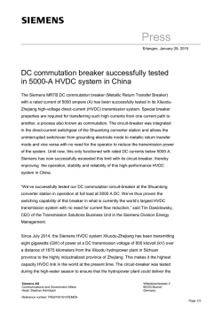
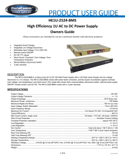
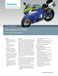

© Copyright 2026