
Hydraulic Manual - Sullivan Training Systems
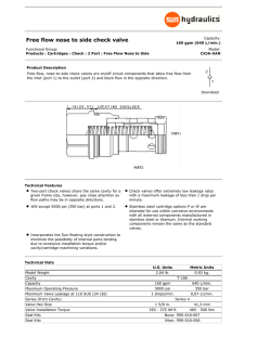
The Secret of
Hydraulic Schematics
© 1997 - 2006 Sullivan Training Systems
brighterIDEAS for Education & Training
Sullivan
w
w
.b
w
rig
ht
er
id
ea
s.
co
m
Table of Contents
The Secret to Reading and Interpreting Hydraulic Schematics ................................................. 1
Hydraulic System Schematics ................................................................................................................ 1
Reservoirs ....................................................................................................................................................... 2
Hydraulic Lines, Tubes & Hoses .............................................................................................................
3
.............................................................................................................3
Pumps .............................................................................................................................................................. 5
Hydraulic Motors ......................................................................................................................................... 7
Hydraulic Cylinders ..................................................................................................................................... 8
Area, Volume & Cycle Time ..................................................................................................................... 10
Pressure Control Symbols ....................................................................................................................... 11
Pressure Relief Valve ................................................................................................................................ 12
Sequence Valve ........................................................................................................................................... 13
Pressure Reducing Valve ......................................................................................................................... 14
Directional Control Valves ...................................................................................................................... 15
Two Position Flow Control Valves .......................................................................................................... 17
Three Position Flow Control Valves ..................................................................................................... 18
How Valves Are Actuated ...................................................................................................................... 19
Flow Control Mechanisms ...................................................................................................................... 20
Fluid Conditioning Mechanisms and Symbols .................................................................................. 21
Accumulators ............................................................................................................................................. 22
Miscellaneous Mechanisms and Symbols ........................................................................................ 23
Reading and Interpreting Hydraulic Schematic S ymbols
Sullivan
Brighter Ideas for Education & Training
Page 1
The Secret to Reading and Interpreting
Hydraulic System Schematics
The secret to being successful at reading and interpreting a schematic for a hydraulic system
is really quite simple. Very often, technicians will forget that the symbols on schematics are
really a completely different language of pictographs — pictures of what the object does —
used to represent the component. As you read this manual and begin to study the symbols
inside, go to the extra effort to try and figure out why the symbols are drawn as they are. If
you think about it, pumps will look like what pumps do, and all of the other symbols will come
close to looking like what they are intended to be.
As
1.
2.
3.
you read the schematic, remember the following:
You already have a good idea of what the machine does and how the components work.
The schematic is a picture of the machine, which does what you understand.
Therefore, whether it looks like it or not, the schematic and the machine match
match.
Don’t forget what you already know when you pick up a schematic — use what you know to
force the schematic to make sense. Take the time to learn what the system is supposed to
do. This is what a schematic is for — to teach why a system does what it does.
If you get lost
lost, remember that you always have to have fluid flowing, and as it flows it follows
this path: starting at the pump, fluid flows from high pressure to low, and ends up back at
the reservoir.
Good luck.
Reading and Interpreting Hydraulic Schematic Symbols
Sullivan
Brighter Ideas for Education & Training
Page 1
Reservoirs
Reservoirs are used to contain fluid, provide cooling, separate out air and sludge, and provide
a head pressure to the pump if the reservoir is pressurized.
VENTED RESERVOIR
PRESSURIZED RESERVOIR
PRESSURIZED RESERVOIR PRESSURIZED RESERVOIR
Reservoirs can also be drawn to show the point of connection for suction and return lines.
VENTED RESERVOIR
OIL RETURN ABOVE OIL LEVEL
VENTED RESERVOIR
SUCTION LINE
ATTACHED TO BOTTOM
VENTED RESERVOIR
OIL RETURN BELOW OIL LEVEL
Reading and Interpreting Hydraulic Schematic Symbols
Sullivan
Brighter Ideas for Education & Training
Page 2
Hydraulic Lines, Tubes & Hoses
Hydraulic lines, tubes and hoses (or any other conductor) that carry the fluid between components is drawn as a line.
PRESSURE OR
RETURN LINE
OIL FLOWS
IN ONE DIRECTION
PILOT LINES
DRAIN LINES
GASEOUS SUPPLY
SHOWING DIRECTION
OUTLINE FOR
ENCLOSURE
Reading and Interpreting Hydraulic Schematic Symbols
OIL FLOWS
IN BOTH DIRECTIONS
FLEXIBLE LINE
INSTRUMENT
LINE
Sullivan
Brighter Ideas for Education & Training
Page 3
Hydraulic Lines, Tubes & Hoses (continued)
Connections for lines and hoses are shown below. Pay particular attention to the presence of
a “dot” at the intersection of lines. If there’s no “dot” visible and lines cross, the lines do not
connect. If lines intersect but one line ends, then even without a “dot” the lines do connect.
LINES
CONNECTED
LINES
CONNECTED
LINES
CONNECTED
LINES NOT
CONNECTED
LINES NOT
CONNECTED
LINES NOT
CONNECTED
Reading and Interpreting Hydraulic Schematic Symbols
Sullivan
Brighter Ideas for Education & Training
Page 4
Pumps
Pumps are drawn as circles with triangles pointing outward from the center. The triangle represents the direction that fluid flows out of the pump and should be viewed as an arrow. A
single arrow shows a one-direction (unidirectional) pump, while two arrows indicate a reversible
(bidirectional) pump. A diagonal arrow cutting across the pump body indicates the pump displacement (output flow and volume) can be adjusted. A small rectangle on the side of the
pump with a small arrow inside indicates that the pump output is compensated (adjusted or
controlled) by a pressure signal from a pilot line.
INLET
FIXED DISPLACEMENT
UNIDIRECTIONAL
FIXED DISPLACEMENT
REVERSIBLE
OUTLET
VARIABLE
DISPLACEMENT
Reading and Interpreting Hydraulic Schematic Symbols
Sullivan
VARIABLE DISPLACEMENT
PRESSURE COMPENSATED
Brighter Ideas for Education & Training
Page 5
Pumps (continued)
Pumps are also drawn to indicate how their output can be controlled. Note that the attachments to the pumps look like the components they represent. The lever and pedal look like a
lever and pedal. The drive shaft is shown as a pair of lines on the side of the pump, either with
or without an arrow showing the direction of rotation. Pumps can also be drawn as stacks,
which indicates that all pumps are driven by the same driveshaft or PTO.
LEVER
CONTROLLED
PEDAL
CONTROLLED
PUMP WITH
DRIVE SHAFT
DRIVE SHAFT
SHOWING DIRECTION
PUMP STACK
Reading and Interpreting Hydraulic Schematic Symbols
Sullivan
Brighter Ideas for Education & Training
Page 6
Hydraulic Motors
Hydraulic motors are actually hydraulic pumps that work in reverse. Except for a few minor
differences pumps and motors are virtually identical. Use the same rules to interpret motor
symbols as you would pump symbols.
OUTLET
NON-REVERSIBLE
MOTOR
REVERSIBLE
MOTOR
INLET
BI-DIRECTIONAL
PRESSURE COMPENSATED
Reading and Interpreting Hydraulic Schematic Symbols
Sullivan
MOTOR WITH
DRIVE SHAFT
Brighter Ideas for Education & Training
Page 7
Hydraulic Cylinders
Hydraulic cylinders convert fluid power to linear mechanical power. Fluid under pressure pushes
against the ends of the piston to move it in order to move some other mechanism. Cylinders
are drawn as rectangles with lines in the center to represent the piston
piston, and lines through the
ends to represent the rod
rod. Fluid ports are shown on the outer ends of the cylinder barrel
barrel.
A single-acting cylinder only has one port so that fluid under pressure only enters one end and
pushes only in one direction. The cylinder reverses by opening a valve to let gravity or a spring
return the piston to the other end.
A double-acting cylinder has ports at each end so pressurized fluid will enter both ends and
push against the piston in both directions.
PORT
PISTON
ROD
BARREL
TYPICAL HYDRAULIC CYLINDER
Reading and Interpreting Hydraulic Schematic Symbols
Sullivan
Brighter Ideas for Education & Training
Page 8
Hydraulic Cylinders (continued)
SINGLE-ACTING CYLINDER
DOUBLE-ACTING CYLINDER
DOUBLE ROD-END CYLINDER
DIFFERENTIAL CYLINDER
SINGLE ROD END WITH A
FIXED CUSHION AT BOTH ENDS
Reading and Interpreting Hydraulic Schematic Symbols
SINGLE ROD END WITH ADJUSTABLE
CUSHION ON ROD END ONLY
Sullivan
Brighter Ideas for Education & Training
Page 9
Area, Volume & Cycle Time
The speed at which a cylinder moves is based upon the fluid flow rate (in gallons/minute or
Cycle time
cubic feet/minute) and the volume (displacement) of the piston. “Cycle
time” is the time it
takes a cylinder to move its full length, and is found by dividing the displacement of the cylinder (area x stroke) by the flow rate, then multiplying by 60 seconds
seconds. Cycle time is critical in
diagnosing a hydraulic problem.
AREA
Area = 3.14 x radius
STROKE
2
VOLUME (CID) = Area x Stroke
CYCLE TIME = (Volume/Flow Rate) x 60
150 cu. in. cylinder
450 cu. in. per minute flow x 60 sec = 0.333 x 60 = 20 sec
Volume and Displacement are the same, and are found by multiplying area times length. When
calculating cycle time, make sure you use the same units of measurement. Cubic feet per
minute cannot be used with gallons, and vice versa.
Reading and Interpreting Hydraulic Schematic Symbols
Page 10
Sullivan
Brighter Ideas for Education & Training
Pressure Control Symbols
Hydraulic pressure is controlled through the use of valves that open and close at different times to allow fluid to be
bypassed from points of high pressure to points of low pressure
pressure. The basic valve symbol is a square which represents the
valve body or spool
spool. An arrow in the center represents the path oil takes through the valve.
Pressure control valves are typically pilot operated — that is, the valve is moved automatically by hydraulic pressure and
not by a person. Pilot oil pressure is resisted by a spring, which can often be adjusted. The higher the spring tension, the
more fluid pressure is required to move the valve
valve.
To visualize the operation of this type of valve, imagine that the entire square will move away from the pilot line and towards the spring. If the valve is normally-open
normally-open, fluid flow will be cut off by the pilot line. If the valve is normally-closed
normally-closed, the
pilot line will cause oil to start flowing.
Valves can either be on/off valves with no flow in the middle, or infinitely variable, which means flow will gradually increase
or decrease as pilot pressure increases and/or decreases.
SPRING
INLET
SPRING
INLET
PILOT LINE
PILOT LINE
OUTLET
NORMALLY OPEN VALVE
Reading and Interpreting Hydraulic Schematic Symbols
OUTLET
NORMALLY CLOSED VALVE
Sullivan
Brighter Ideas for Education & Training
Page 11
Pressure Relief Valve
A pressure relief valve is a normally closed valve that senses the high pressure at its inlet. As
the pressure at the inlet increases, the pressure in the pilot line begins to push against the
valve body (spool). As the valve body moves, the ports begin to line up and fluid will begin flowing through the relief valve. The relief valve typically dumps back into the reservoir. Most relief
valves are infinitely variable.
PRESSURE RELIEF VALVE
Reading and Interpreting Hydraulic Schematic Symbols
Sullivan
Brighter Ideas for Education & Training
Page 12
Sequence Valve
A sequence valve is a normally closed valve that opens once the inlet pressure reaches a preset point. This type of valve is designed to allow different components to act “sequentially”,
meaning one after the other. Once the primary actuator reaches the limit of its travel fluid
pressure in the feed line will rise. This rising pressure opens the sequence valve which allows
fluid to flow through it to the secondary cylinder.
TO PRIMARY CYLINDER
SEQUENCE VALVE
TO SECONDARY CYLINDER
Reading and Interpreting Hydraulic Schematic Symbols
Sullivan
Brighter Ideas for Education & Training
Page 13
Pressure Reducing Valve
A pressure reducing valve is a normally open valve that senses the outlet pressure going to an
actuator. As the pressure in the outlet increases, pilot pressure increases which gradually
closes the reducing valve. As the valve closes, oil from the high pressure side of the valve is
directed back to the reservoir which dumps pressure at the outlet.
OR
PRESSURE REDUCING VALVE
Reading and Interpreting Hydraulic Schematic Symbols
PRESSURE REDUCING VALVE
Sullivan
Brighter Ideas for Education & Training
Page 14
Directional Control Valves
The direction that fluid flows in a line can be controlled by using valves which allow flow in only
one direction. These valves are typically referred to as “check valves” because they “check” the
flow if it tries to reverse. These valves can have simple check balls or can have machined poppet type valves. They can also be more complex pilot operated valves that have spools.
ball. If
In the case of a ball check valve, the allowed flow is opposite the arrow, or towards the ball
the valve has no spring, the valve offers resistance to flow only in the “closed” direction; in the
“open” direction the valve moves with any movement of fluid and does not have a pressure setting.
If the check valve has a spring it will oppose flow in the “open” direction up to the point where
hydraulic pressure overcomes spring tension. Check valves can also be pilot operated.
NO FLOW
FREE FLOW
ONE WAY VALVE (CHECK VALVE)
BY-PASS VALVE
(SPRING LOADED CHECK VALVE)
Reading and Interpreting Hydraulic Schematic Symbols
PILOT OPERATED
BY-PASS VALVE
Sullivan
Brighter Ideas for Education & Training
Page 15
Directional Control Valves (continued)
Another method of drawing check valves (directional valves) is using composite symbols as in the previous
sequence. This method contains a blocked path and a free path. The dashed lines represent pilot pressure lines. As pressures increase on the blocked side of the valve, that pilot line moves the valve to reduce
or cut off supply, depending upon whether the valve is normally open or closed.
The spring keeps the valve in the normal position
position. If pressure builds up on the flow side of the valve, the
pilot line pressurizes and moves the valve into the open position, compressing the spring in the process,
and allowing oil to flow. If the flow attempts to reverse, the other pilot line pressurizes and adds to spring
pressure to close the valve, cutting off flow.
These valves are commonly referred to as flow dividers or flow control valves. This type of valve can be a
pressure relief valve or pressure reducing valve depending upon location of pilot source and spring setting.
FREE FLOW
NO FLOW
ONE WAY VALVE
SHOWN CLOSED
PILOT PRESSURE FROM
RIGHT PUSHES VALVE
UPWARD TO ALLOW FLOW
Reading and Interpreting Hydraulic Schematic Symbols
Sullivan
Brighter Ideas for Education & Training
Page 16
Two Position Flow Control Valves
Two position flow control valves typically are used to make the flow reverse to an actuator in a
simple system, although other arrangements are possible. The valve spool slides long-ways to
allow one or the other valve position to direct flow. Because these valves have no center position they must be used with a pressure relief valve that opens to dump system pressure when
the actuator bottoms out.
Note that the direction of oil flow does not change on the pump side of the valve
valve. The direction changes only after the valve “flip-flops” the flow to redirect pressure to the retracted side
of the cylinder.
Reading and Interpreting Hydraulic Schematic Symbols
Sullivan
Brighter Ideas for Education & Training
Page 17
Three Position Flow Control Valves
Flow control valves are drawn as composite symbols using squares to represent the valve
spool. To visualize the operation of these valves it’s necessary to imagine them moving longways with the spool sliding to move the different flow arrows into a position to allow oil to flow
through them.
The centers of the valves determine what type of system is in use. An “open center” system
uses valves that allow oil to flow through them at all times — out of the pump and back into
the reservoir — when no actuators are in use. This system does not require a pressure relief
valve.
A “closed center” system uses valves that block flow through them when no actuators are in
use, thereby “liquid locking” the system. In this type of system a pressure relief valve is mandatory to prevent the system from destroying itself when the valves are in the center.
OPEN CENTER VALVE & SYSTEM
Reading and Interpreting Hydraulic Schematic Symbols
CLOSED CENTER VALVE & SYSTEM
WITH PRESSURE RELIEF VALVE
Sullivan
Brighter Ideas for Education & Training
Page 18
How Valves Are Actuated
There are a variety of ways to actuate control valves. These include manually by hand with a
lever, manually by foot with a pedal, with an electric solenoid (coil), using external pilot pressure, using a spring, using internal pilot pressure, or using any combination of the above.
LEVER CONTROLLED
SOLENOID CONTROLLED
PEDAL CONTROLLED
(NOT JUST ON AND OFF)
PILOT PRESSURE
CONTROLLED
SOLENOID OPERATED WITH
INTERNAL PILOT PRESSURE
SOLENOID OPERATED WITH INTERNAL
PILOT PRESSURE AND SPRING CENTERING
INFINITELY VARIABLE
Reading and Interpreting Hydraulic Schematic Symbols
Sullivan
Brighter Ideas for Education & Training
Page 19
Flow Control Mechanisms
Sometimes it’s necessary to slow down flow or to create a pressure drop at some point in the
system. This is done with a restrictor (snubber) that is similar to a fuel jet. Snubbers are
drawn to represent a pinch in the line, and can either be fixed or variable, and can be controlled by other systems as well — such as being temperature or pressure controlled.
FIXED RESTRICTOR
ADJUSTABLE RESTRICTOR
ADJUSTABLE
RESTRICTOR
PRESSURE COMPENSATED
ADJUSTABLE RESTRICTOR
PRESSURE & TEMPERATURE
COMPENSATED
Reading and Interpreting Hydraulic Schematic Symbols
Sullivan
Brighter Ideas for Education & Training
Page 20
Fluid Conditioning Mechanisms and Symbols
Oil is conditioned by various mechanisms. “Conditioned” implies that the condition of the oil is
changed from one state to another. Typical conditioners are filters, heaters and coolers. In
addition, these mechanisms can contain drains of various sorts.
FILTER OR STRAINER
COOLER
HEATER
TEMPERATURE CONTROL UNIT
MANUAL DRAIN
SEPARATOR
AUTO DRAIN
SEPARATOR
MANUAL DRAIN
FILTER SEPARATOR
AUTO DRAIN
FILTER SEPARATOR
Reading and Interpreting Hydraulic Schematic Symbols
Sullivan
Brighter Ideas for Education & Training
Page 21
Accumulators
Hydraulic accumulators act as shock absorbers for the system. They are installed in parallel
with the pump and do several things. They provide a small amount of emergency flow for
steering and brakes, dampen out oscillations in pressure (keeping pressure constant), and provide flow when components move and activate. They’re drawn as ovals with a line in the center
which represents the diaphragm or piston that separates the oil from the nitrogen or spring.
PNEUMATIC
(GAS FILLED)
ACCUMULATOR
Reading and Interpreting Hydraulic Schematic Symbols
SPRING
LOADED
ACCUMULATOR
Sullivan
Brighter Ideas for Education & Training
Page 22
Miscellaneous Mechanisms and Symbols
QUICK DISCONNECTS
(CONNECTED)
PRESSURE SWITCH
TEST POINT FOR GAUGE
QUICK DISCONNECTS
(DISCONNECTED)
SPRING
RATCHETING DETENT
ON VALVE
MANUAL SHUTOFF VALVE
TEMPERATURE
INDICATOR
PRESSURE
INDICATOR
Reading and Interpreting Hydraulic Schematic Symbols
Sullivan
Brighter Ideas for Education & Training
Page 23
©1997 - 2006
Sullivan Training Systems
115 Honeysuckle Lane
Durham NC 27703
919-957-1800
www.brighterideas.com
brighterIDEAS in Technician Training
This text may be reproduced for training purposes by any person or
school provided that it is duplicated in its entirety, complete with all
logos and identifying marks. Modification of this document in any
way constitutes a violation of this agreement.
Please visit our wesbite to view the new tools and texts currently
available.
Feel free to email this document at will to friends and colleagues who
work with hydraulics.
© Copyright 2026