
Bypass Systems Designed to Improve Efficiency and Flexibility of
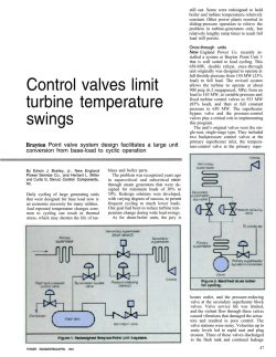
Bypass Systems
Designed to Improve
Efficiency and
Flexibility of Thermal
Power Plants
...................................................
By Ulrich Kägi
22591 Avenida Empresa
Rancho Santa Margarita, CA 92688
949.858.1877 ! Fax 949.858.1878 ! ccivalve.com
390
|
06/00 ! ©2000 CCI ! DRAG is a registered trademark of CCI.
In the early 1930’s new boiler types, e.g., the Sulzer monotube
Bypass Systems Designed
to Improve Efficiency and
Flexibility of Thermal
Power Plants
steam generator, were developed. Because this boiler did not have
a large accumulator in the form of a steam drum anymore, it
required automatically controlled valves and a fully automatic
control system for stable operation. The boiler was started up
with the evaporator and superheater full of water and already
" By Ulrich Kägi, CCI AG (Switzerland)
under pressure. It required therefore a bypass valve at the
Presented at the Future Strategies and Technologies for Development
of Thermal Power International Conference, Dec. 14–17, 1999,
in New Delhi, India
outlet of the boiler to control the boiler pressure immediately
after light-off, when the water in the boiler expanded and
Abstract
this type of boiler successfully.
steam production started. A fully hydraulic control system and
hydraulically operated valves were developed in order to operate
T
urbine bypass valves were first used in the early 1930’s with the
newly developed once-through steam generators. Today, bypass
With the development of boilers with reheaters, bypass systems
as we know them today, with HP- and LP-bypass, were
introduced. Fig.1 shows the water/steam cycle of a single reheat
systems are not only essential for the flexible operation of large
coal fired power plants, but play an equally important role in
power plant with HP- and LP-bypass. In the effort to increase
advanced combined cycle power plants. Bypass systems permit the
efficiency and reduce cost per installed megawatt, unit sizes were
boiler and the steam turbine to be separated during startup, shut-
increased along with higher temperatures and pressures at the
down and load disturbances. This reduces fuel consumption and
superheater and reheater outlet. In the 1960’s the first plants were
enhances operational flexibility during all those transient operating
operated in sliding pressure mode.
modes. Startup and reloading times—and therefore fuel costs—are
reduced. Other advantages are reduced lifetime consumption of
In continental Europe it became customary to utilize the
HP-bypass valves as safety valves to protect the superheater
major plant components, and higher overall availability of the
against excessive pressure. The design of the bypass valves had
plant. The latest bypass-valve technology improvements make sure
that bypass systems fulfill all the operational requirements of
to follow the trend of ever-increasing steam flow together with
higher temperature and pressure. In the 1970s, bypass systems
today’s advanced thermal power plants. Longer overhaul cycles and
reduced maintenance are important features in today’s increasingly
competitive market. New plants are not the only ones that
were applied in increasing numbers also to enhance the flexibility
of large drum type boiler units. The Indian power industry was at
the forefront of bypass application in these power plants.
can profit from the advantages of state-of-the-art bypass systems.
Bypass systems can be added to existing plants, and existing bypass
2. Function of Turbine Bypass Systems
valves can be upgraded to the latest technologies.
Turbine bypass systems can contribute to flexible plant operation
1. Introduction
mainly by supporting:
"
Repeatedly attainable fast startups
with the greatest possible regard to the
lifetime of heavy-walled components.
HP
IP
LP
"
Quickest possible restoration of
power supply to the grid after any disturbance
G
PT
PT
1
3
2
77
C
1
2
3
HP-Bypass Valve
Spraywater Control Valve
Spraywater Isolation Valve
Therefore, bypass systems contribute to the
6
7
8
LP-Bypass Control Valve
Desuperheater
Spraywater Control Valve
electric power at minimum total cost.
CL
2.1
7
PT
overall target of safe and efficient supply of
Plant startup
During unit startup, the bypass system
6
essentially allows the separation of boiler and
TT
C
8
turbine operations by diverting all the steam,
which cannot be accepted by the turbine or
other consumers, through the bypass. This
allows the boiler to reach the desired steam
Figure 1—Single Reheat Plant with HP- and LP-Bypass
2
Bypass Systems Designed to Improve Efficiency and Flexibility of Thermal Power Plants | 390
qualities as quickly as possible to start the
turbine.
©2000 CCI. All rights reserved.
Without a bypass it is difficult to control two output variables
of the boiler (pressure and temperature) with only one input
o
C
500
bar
300
4.2
variable, the firing rate. If there is no steam flow through the
reheater and almost no steam flow through the superheater, the
firing rate is limited to very low values. Such low firing rates
400
4.1
300
200
do not allow a quick warm-up of the boiler. Increased slagging
200
and fouling of the boiler can be, besides high fuel consumption,
the result of slow warm-up. Because of the low boiler load, the
attainable superheater outlet temperature is limited. Changes in
%
100
0
100
100
the firing rate will always affect pressure and temperature. Fast
pressure transients during startup are not desirable because they
result in temperature transients in heavy-walled parts, such as the
3.2
boiler drum or the startup separator.
2.1
The bypass therefore allows faster boiler warm-up through higher
boiler load, reduces thermal transients in the boiler, and by
Bypass
Operation
2.3
2.2
1.1
2.4
attaining good steam-to-metal temperature matching also allows
0
0
shorter turbine startup times with reduced life time consumption.
Light up
2.1.1 The HP-Bypass During Hot Start
100
50
Synchr.
min
Full Load
Pulverizers
The hot start characteristics of a coal-fired 500 MW unit (Fig.
2) shows how a bypass system can contribute to a quick and
lifetime-saving startup. The boiler is a once-through type with
nominal superheater outlet conditions at full load of 254 bar
1.1 Firing Rate
2.1
2.2
2.3
2.4
Feedwater Flow
Waterwall Flow
Steam Flow (Superheater)
Steam Flow (Turbine)
3.1 Superheater Pressure
3.2 Reheater Pressure
4.1 Superheater Temperature
4.2 Reheater Temperature
(3683 psig) and 541oC (1000oF). After an overnight shutdown the
unit is restarted at a superheater pressure of approx. 80 bar (1160
Figure 2—Hot start of a coal-fired supercritical 500 MW unit
psig). This is, at the same time, the pressure for turbine start,
so no large pressure transients are to be expected. Immediately
In the startup diagram of Fig. 2, the reheat pressure during startup
after light-up, the bypass opens and starts to control constant
is kept at 12 bar (175 psig). This keeps the exhaust pressure of the
pressure. The firing rate is quickly increased in order to match
HP-Turbine low enough to avoid overheating of the last turbine
the superheater outlet temperature with the turbine metal
stages through ventilation losses. The LP-bypass must therefore
temperature. For this unit, the desired steam temperature after
be sized for the startup flow at this reduced pressure.
an overnight shutdown is approximately 450 oC (842 oF). Two
2.2 Load rejection
pulverizers are started before the turbine is started. This keeps
temperature transients, invariably associated with the start of the
2.2.1 HP-Bypass
first pulverizers, away from the heavy wall turbine parts. The
An HP-bypass with capacity of 100% BMCR at rated pressure can,
bypass compensates for load swings originating from pulverizer
in case of a load rejection or a turbine trip, immediately take
start. The reheater pressure is quickly increased to approx. 12 bar
over all excess steam. This has the following advantages for the
(175 psig) which allows auxiliary steam to be supplied from the
plant operation:
reheater.
2.1.3 The LP-Bypass During Startup
" The boiler can remain in operation and immediate reloading
of the turbine is possible
The LP-bypass is diverting the hot reheated steam directly to the
" No lift of superheater safety valves
condenser. The LP-bypass should have at least a capacity which
is equal to the HP-bypass flow during startup, including the
" Superheater and reheater are continuously cooled by steam
flow
HP-bypass spraywater flow. The reheater pressure during startup
is determined by various considerations:
" Unnecessary pressure and temperature transients are avoided
" Use of reheat steam as auxiliary steam
" The boiler can run back to a stable minimum load in a
controlled manner
" Desired reheat pressure for IP/LP turbine warming
" Desired HP-turbine exhaust pressure for startup
©2000 CCI. All rights reserved.
" No immediate pulverizer trips are necessary
" House load operation is possible
390 | Bypass Systems Designed to Improve Efficiency and Flexibility of Thermal Power Plants
3
" Reheat steam is available as auxiliary steam
3. Turbine Bypass Systems
in Combined-Cycle Power Plants
" Part load trip in sliding pressure mode without unnecessary
pressure transients
Bypass systems are not only essential for flexible operation of
large coal-fired power plants, they are also part of any of today’s
A smaller bypass of 60–70% MCR usually allows the keeping
advanced combined-cycle power plants. Fig. 4 shows the bypass
of the boiler in operation. At high loads the superheater safety
system of an advanced Combined Cycle Power Plants (CCPP)
valves will have to open for a brief period and pressure and
with a three-pressure Heat Recovery Steam Generator (HRSG).
temperature transients are not avoided completely.
2.2.2
LP-Bypass
The purpose of the bypass system in this type of power plant
bar Pressure
is in principle the same as in the coal-fired plants. It has to
40
compensate for the differences in the startup sequence between
Due to limited
the steam generator and the steam turbine. The steam production
capacity of the
of the boiler is determined primarily by the gas turbine operation
condenser, the
LP-bypass
and therefore the available thermal energy at the outlet of the gas
20
turbine. By controlling the steam flow of the HRSG, it is possible
usually cannot
dump 100%
to reach the steam conditions desired for a smooth and lifetime10 bar
saving start of the steam turbine. Sizing considerations are similar
MCR flow into
Flow
the condenser.
When
determining the
maximum
allowable
Bypass Flow 25%
50
100
%
Flow limitation
Boiler Flow 35%
Turbine House Load Flow 10%
to those for a coal-fired power plant. The possible separation of
the steam generator and the steam turbine during disturbances
plays an even-more-important role in the CCPP because the
steam generator operation is directly coupled with the gas
turbine. The separation therefore allows independent operation
Figure 3—LP-Bypass After Load Rejection
LP-bypass flow,
the high LP-bypass spraywater flow of approx. 25% of steam flow
has to be taken into account. On the other hand, it is desirable
from a turbine operating point of view, to have for house load
operation and reloading a HP-Turbine exhaust pressure as low as
possible, and therefore a large LP-Bypass.
of gas and steam turbines.
4. Design Considerations
Bypass systems are installed to enhance the flexibility of power
plant operation and to protect and save life-time of critical plant
components. Bypass systems are themselves subject to frequent
high thermal stress caused by normal startups and shutdowns
The result of the two contradictory requirements is very
often a LP Bypass with a 100% MCR capacity at full
reheat pressure but a flow limitation introduced in the
control system. Fig. 3 illustrates house load operation
with an LP-bypass.
The operating conditions are assumed as follows:
" Minimum stable boiler load approx. 35%
" Required steamflow for house load approx. 10%
" LP-bypass flow (including HP-bypass spraywater)
approx. 25% MCR
" Max. reheat pressure of 10 bar (145 psig) at house
load (25% of full load pressure)
1
GT
HP
IP
LP
G
As Fig. 5 shows, the resulting size of the LP-bypass
valves is 100% MCR at full reheater pressure.
3
If the maximum allowable flow through the LP-bypass
is less than 100%, the reheater safety valves will have to
open in the initial phase of a load rejection from full
1
2
3
HP-Bypass
IP-Bypass
LP-Bypass
2
load. The reheat safety valves have to dump the excess
steam to atmosphere until the boiler has been run back
to a load corresponding to the capacity of the LP-bypass.
4
Figure 4—Bypass Ssytem in a Combined-Cycle Power Plant
Bypass Systems Designed to Improve Efficiency and Flexibility of Thermal Power Plants | 390
©2000 CCI. All rights reserved.
as well as disturbances in the plant operation. Additional stress
The wing-type plug used in this
is caused by the inherent function of pressure and temperature
valve has evolved over many years
reduction. Bypass valves must be designed so that they are not by
of experience and is the best-
themselves a limitation to the operational flexibility of the plant
suited stem shape for this type
and never result in additional stress or damage to the plant.
of valve. The wings split up
the steam flow into a number
Goals of a good bypass valve design are therefore:
of small jets, which efficiently
" Tolerance to frequent high thermal stress due to pressure and
temperature transients
reduces noise and vibration inside
" Little regular maintenance required for any mechanical
components
The valve-in features integrated
the valve.
spraywater injection. Proper
" Easy accessibility to all valve internals for inspection and
maintenance
design of an integrated injection
requires a detailed understanding
" Replacement of any parts must be possible without cutting the
valve out of the pipe
valve during all load conditions.
In order to achieve the above goals, the following rules should be
Analysis and optimization of
applied for the design of bypass valves:
these flow patterns including
" Thin pressure boundary walls reduce actual thermal stress in
the material due to temperature transients
of the flow pattern inside the
Figure 5—HP-Bypass Valve
spraywater atomization and
evaporation is today possible with dynamic numerical
calculation.
" Spherical shapes result in the thinnest-possible pressure
boundary walls for given pressure and temperature
" Smooth transitions between different wall thicknesses and no
unnecessary material accumulation
" Pressure boundary walls must be protected from being hit by
spraywater
" Avoid thermal stress due to temperature differences in any
parts which are already subject to high mechanical stress (e.g.,
no spraywater injection through valve stems)
The spray water is injected through a high number of small
injection nozzles directly into the zone of highest turbulence of
the steam flow. This ensures excellent atomization of the injected
water, good mixing with the steam, and due to the small droplet
size, very fast evaporation of the injected water. The spraywater
nozzle body which is subject to the differential temperature
between steam and injection water is not under mechanical load.
The cage around the desuperheating area prevents the pressureretaining walls from being hit by water droplets, which would
" Efficient cooling of the steam by good mixing and evaporation
of the injected water
cause high local thermal stress. Hole pattern, shape and material
" Good atomization of the injected spraywater by high injection
speed or injection into the high steam turbulence zone
integrated injections.
selection of the cage are the result of long experience with
Due to the optimal atomization and evaporation of the
" Good mixing of the injected water by high turbulence or deep
penetration of the injected water into the steam jet
spraywater, the water is essentially evaporated at the outlet of
the valve which gives maximum freedom in placing the valve in
" All parts must be accessible and exchangeable from the top
the plant.
The following examples of an HP- and an LP-bypass valve show
4. 2 LP-Bypass Valve
the application of the above listed design rules.
In the LP-bypass valve shown in Fig. 6, the steam flows in the
closing direction. This is the normal flow direction for LP-bypass
4.1 HP-Bypass Valve
Fig. 5 is a sectional drawing of an HP-bypass valve. Since this
valve is designed to be used also as a combined bypass and safety
valves because the LP-bypass usually has a safe closing function
to protect the condenser from too high a thermal load.
valve, the steam flow is in the opening direction of the valve.
The valve has an inlet cage, seat ring and outlet cage, all easily
Because the high pressure (thick wall) part of the valve consists
removable from the top.
essentially only of the inlet nozzle, this design minimizes
stress due to thermal cycling. The valve body has a spherical
shape to minimize the wall thickness. Any unnecessary material
accumulation is avoided. The valve is especially suited as an
HP-bypass for supercritical plants.
©2000 CCI. All rights reserved.
The spraywater is injected downstream of the valve through
spring-loaded nozzles. The outlet cage is guiding the steam flow
towards the spray nozzles. The spring-loaded nozzles ensure a
minimum injection pressure for all flow rates, and therefore a
high injection velocity and good atomization. High spraywater
390 | Bypass Systems Designed to Improve Efficiency and Flexibility of Thermal Power Plants
5
velocity results also in deep
penetration of the injected
safety valves with sliding pressure opening mode, it is the
water into the steam jet
LP-bypass controller which generates the signals to keep the
at the outlet of the valve,
reheater safety valves open as long as there is too much reheat
and therefore good mixing
steam flow to be dumped only through the LP-bypass.
of water and steam. The
defined injection velocity
makes sure that the injected
water is not hitting the
pipe walls downstream of
the injection nozzles. The
nozzles are arranged
Figure 6—LP-Bypass Valve
during all operating modes. In case of power-operated reheater
Because the steam conditions after the LP-bypass desuperheater
are usually at or near saturation conditions, the temperature
after injection cannot be used as a control signal. The necessary
injection water flow and corresponding injection valve position
must be calculated on basis of the steam flow and desired
conditions after desuperheating.
around the whole
As mentioned above, the actual signal interchange between the
circumference of the pipe,
HP-/LP-bypass controller and other control systems is small, and
and the number of nozzles
the required functions for startup and other operating conditions
is selected so that a large
can be clearly defined. It is therefore advantageous to procure the
area of the steam jet exiting
bypass system including bypass controller as one package. The
the valve is penetrated by
bypass supplier is best suited to implement all required control
the injection water. All the above design features together result
functions for a smooth operation of the bypass system. This is
in a good water/steam mixing and quick evaporation of the
certainly the case if safety functions and coordination with power
injected spraywater.
operated reheater safety valves are involved.
4.3
5. Conclusion
Turbine Bypass Controller
A well-matched bypass controller will contribute a great deal
The main reason for installing turbine bypass systems is
to the flexible and lifetime-saving operation of the plant. The
improving flexibility in plant operation, especially during startup,
bypass is controlling the boiler pressure during the critical period
shutdown and disturbed plant operation. Benefits of this
of the boiler startup when pressure transients can lead to high
enhanced flexibility are faster startup times, reduced downtime,
unnecessary temperature transients in heavy walled components
and higher availability of the plant, resulting in less fuel costs
of the boiler and the turbine. The key part of the HP-Bypass
and lower overall plant-operating costs. These desired results
pressure controller is the setpoint generator. It has to produce
are only achievable when all components are designed and
the correct setpoint for all the different operating modes during
selected to suit the specific needs of a bypass system, and all
startup, load operation, load rejection and shutdown. Core
components are well-matched. This is achieved when the whole
of the setpoint generator is a rate limiter, which limits the
system—valves, actuators, and controls—are from one supplier
gradient of any pressure increase during all operating modes,
with years of experience in the design and operation of bypass
thus protecting the heavy-walled parts from pressure/temperature
systems and the ability to integrate all components. A good
transients. Operating modes are mainly determined by process
technical specification which addresses all the requirements is a
conditions, namely the superheater pressure and the valve
customer’s most effective instrument in receiving a well-designed
position. The bypass controller is therefore independent and
and matched bypass system. Some design criteria for reliable
does not rely on many signals from the boiler or turbine
bypass valves are listed above.
controller.
6. References
The HP-spraywater control, although at first glance a very simple
1. Assessment of Fossil Steam Bypass Stations
EPRI CS-3717, Final Report, 1984
piece of equipment, has to deal with large variations in process
gain and time delay as well as process disturbances. The use
of an advanced control strategy, i.e., a state controller with
observer (SCO), can considerably improve accurate control under
different operating conditions, and is therefore an important life-
2. R. Rohner, Sulzer Bypass-Systems for Fossil Power Stations
I Mech E Power Conference 1988
3. W. Bung and B. Föllmer, Controlled Safety Valves in Power
Plants in Accordance with the German Standards
VGB Kraftwerkstechnik 75 (1995) Number 9
conserving factor for valves and piping.
The LP-bypass pressure controller controls reheat pressure during
startup and load rejections. Similar to the HP-pressure controller,
it has a setpoint generator producing the correct pressure setpoint
6
Bypass Systems Designed to Improve Efficiency and Flexibility of Thermal Power Plants | 390
©2000 CCI. All rights reserved.

© Copyright 2026