
Atlas V MMS Mission Brochure
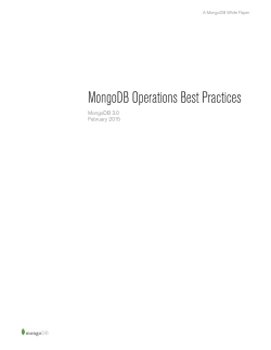
ATLAS V MMS MISSION
A United Launch Alliance (ULA) Atlas V 421 will deliver the MMS
constellation to a highly elliptical orbit (HEO). Liftoff will occur from
Space Launch Complex 41 at Cape Canaveral Air Force Station, FL.
The Magnetoshperic Multiscale mission, or MMS, is a Solar Terrestrial
Probes mission consisting of four nearly identical science observatories
whose objective is to understand the microphysics of magnetic reconnection. The four MMS spacecraft are designed, built, and operated by
Goddard Space Flight Center (GSFC) in Greenbelt, MD.
Magnetic reconnection is a universal process that happens when
magnetic field lines come together, break apart and then exchange
partners, snapping into new positions and releasing a jolt of magnetic
energy. This process lies at the heart of giant explosions on the sun,
such as solar flares and coronal mass ejections, which can fling radiation and particles across the solar system. Because it’s so difficult to see this
process on the sun, and it’s also a difficult process to re-create and study in the lab, researchers plan to take a closer look at magnetic reconnection
in space.
The four identically instrumented MMS spacecraft will fly in an adjustable pyramid-like tetrahedron formation. By observing magnetic reconnection in
nature, MMS provides access to predictive knowledge of a universal process that is the final governor of space weather, affecting modern technological
systems such as communications networks, GPS navigation, and electrical power grids. Magnetic
reconnection also limits the performance of fusion reactors on Earth. Solving magnetic reconnection has the potential to unlock understanding of a fundamental energy process present throughout
the universe that also affects and limits our use of technologies on Earth.
Payload Fairing (PLF)
The MMS spacecraft is encapsulated in the 4-m (14-ft) diameter Extra Extended Payload Fairing
(XEPF). The XEPF is a bisector (two-piece shell) fairing consisting of aluminum skin/stringer construction with vertical split-line longerons. The vehicle’s height with the PLF is approximately 195 ft.
Centaur
The Centaur second stage is 10 ft in diameter and 41.5 ft in length. Its propellant tanks are
constructed of pressure-stabilized, corrosion resistant stainless steel. Centaur is a liquid hydrogen/
liquid oxygen- (cryogenic-) fueled vehicle. It uses a single RL10A engine producing 22,300 lb of
thrust. The cryogenic tanks are insulated with a combination of helium-purged insulation blankets,
radiation shields, and spray-on foam insulation (SOFI). The Centaur forward adapter (CFA) provides
the structural mountings for the fault-tolerant avionics system and the structural and electrical
interfaces with the spacecraft.
Booster
The Atlas V booster is 12.5 ft in diameter and 106.5 ft in length. The booster’s tanks are structurally rigid and constructed of isogrid aluminum barrels, spun-formed aluminum domes, and intertank
skirts. Atlas booster propulsion is provided by the RD-180 engine system (a single engine with two
thrust chambers). The RD-180 burns RP-1 (Rocket Propellant-1 or highly purified kerosene) and
liquid oxygen, and delivers 860,200 lb of thrust at sea level. The Atlas V booster is controlled by
the Centaur avionics system, which provides guidance, flight control, and vehicle sequencing functions during the booster and Centaur phases of flight. The MMS mission uses two SRBs which are
approximately 61 in. in diameter, 67 ft in length, and constructed of a graphite-epoxy composite.
The ULA team is proud to be the launch provider for the Magnetospheric Multiscale (MMS) mission for the National Aeronautics and
Space Administration (NASA). MMS will study the microphysics of
magnetic reconnection to improve our understanding of this fundamental energy process that limits the performance of fusion reactors
on Earth and is the ultimate driver of space weather.
The MMS Project Office at NASA’s Goddard Space Flight Center
manages the spacecraft and our direct customer for this launch is the
NASA Launch Services Program (LSP).
The ULA team is focused on attaining Perfect Product Delivery for the
MMS mission, which includes a relentless focus on mission success
(the perfect product) and also excellence and continuous improvement
in meeting all of the needs of our customers (the perfect delivery).
We sincerely thank the entire team, which consists of NASA, Southwest Research Institute, ULA, and major suppliers of ULA.
Go Atlas, Go Centaur, Go MMS!
Jim Sponnick
Vice President, Atlas and Delta Programs
MISSION OVERVIEW
With more than a century of combined heritage, United Launch Alliance is
the nation’s most experienced and reliable launch service provider. ULA
has successfully delivered more than 90 satellites to orbit that provide
critical capabilities for troops in the field, aid meteorologists in tracking
severe weather, enable personal device-based GPS navigation and unlock
the mysteries of our solar system.
Join the conversation:
ULALaunch.com
Copyright © 2015 United Launch Alliance, LLC. All Rights Reserved.
– 4th Atlas V 421 Launch
– 12th NASA Atlas V Mission
– 53rd Atlas V Launch
ATLAS V PRODUCTION AND LAUNCH
MISSION PROFILE AND GROUND TRACE
1 Sacramento, CA
6
– Solid Rocket Booster Fabrication at
Aerojet Rocketdyne
7
8
9
5
2 Denver, CO
– ULA Headquarters & Design
Center Engineering
4
3 Harlingen, TX
– Payload Fairing, Payload Fairing Adapter, Booste
Booster
ter
Adapter & Centaur Adapter Fabrication
4 Decatur, AL
– Booster Fabrication & Final Assembly, Centaur
entaur
Tank Fabrication & Centaur Final Assembly
bly
5 West Palm Beach, FL
– RL10A Engine Fabrication at Aerojet Rocketdyne
cketdyne
6 Khimki, Russia
– RD-180 Engine Fabrication at
NPO Energomash
1
3
Interstage
Adapter
3
4
5
6
7
8
9
1 Vertical Integration Facility (VIF)
(See inset)
2
2 Bridge Crane Hammerhead
3
3 Bridge Crane
4 Launch Vehicle
Booster
1
4
-2.7
1.1
5.9
48.9
62.5
138.6
249.7
255.7
265.7
273.7
809.0
4,349.8
4,691.3
5,531.3
5,831.3
6,131.3
6,431.3
-00:00:02.7
00:00:01.1
00:00:05.9
00:00:48.9
00:01:02.5
00:02:18.6
00:04:09.7
00:04:15.7
00:04:25.7
00:04:33.7
00:13:29.0
01:12:29.8
01:18:11.3
01:32:11.3
01:37:11.3
01:42:11.3
01:47:11.3
80
5
7 High Pressure Gas Storage
8 Booster LO2 Storage
60
5
9 Pad Equipment Building (PEB)
LION
BOSS
40
10 Pad ECS Shelter
Spacecraft
RD-180 Engine Ignition
Liftoff (Thrust to Weight > 1)
Begin Pitch/Yaw Maneuver
Mach 1
Maximum Dynamic Pressure
SRB Jettison
Atlas Booster Engine Cutoff (BECO)
Atlas Booster/Centaur Separation
Centaur Main Engine Start (MES-1)
Payload Fairing Jettison
Centaur First Main Engine Cutoff (MECO-1)
Centaur Second Main Engine Start (MES-2)
Centaur Second Main Engine Cutoff (MECO-2)
First MMS Separation (MMS-4)
Second MMS Separation (MMS-3)
Third MMS Separation (MMS-2)
Fourth MMS Separation (MMS-1)
Longitude (deg)
6 Centaur LO2 Storage
Centaur
Time
(hr:min:sec)
Perigee Altitude: 316 nmi | Apogee Altitude: 37,886 nmi | Inclination: 28.77 deg | Flight Azimuth: 99.0 deg
2
5 Mobile Launch Platform (MLP)
Time
(seconds)
COOK
ER
4-m Payload
Fairing Halves
20
Payload
Transporter
0
8
6
HULA
9
TDRS 46
Guam
TDRS 171
TDRS 275
TDRS 174
2
1
Solid Rocket Boosters
-40
-60
4
3
TDRS 41
-20
1
Telemetry Ground Station
Launch Vehicle /Spacecraft Groundtrack
TDRS Asset Geostationary Orbital Position
-80
6
-135
Mobile
Launch
Platform
7
Space Launch Complex 41
7
-90
-45
0
45
90
135
8
All Values Approximate
Geodetic Latitude (deg)
SOC) | Launch
1 Atlas Spaceflight Operations Center (ASOC)
Control Center and Mission Director’s Centerr
2 Spacecraft Processing Facility | Spacecraft
aft processing,
testing and encapsulation
3 Vertical Integration Facility | Launch vehicle Integration
and testing, spacecraft mate and integrated operations
2
Event
© Copyright 2026